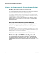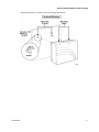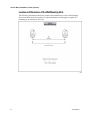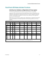
1
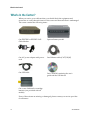
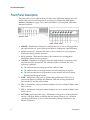
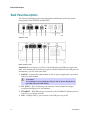
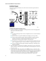
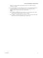
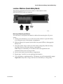
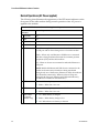
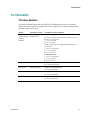
October 2006 DPC2203 and EPC2203 VOIP Cable Modem User's Guide In This Document IMPORTANT SAFETY INFORMATION ................................................................2 FCC Compliance .........................................................................................................7 What's In the Carton? ...............................................................................................10 Front Panel Description ...........................................................................................12 Back Panel Description.............................................................................................14 Where Is the Best Location for My Cable Modem?..............................................16 What Are the System Requirements for Internet Service?..................................17 How Do I Set Up My High-Speed Internet Access Account?.............................18 How Do I Connect My Devices to Use the Internet? ...........................................19 How Do I Configure TCP/IP Protocol?.................................................................21 How Do I Install USB Drivers? ...............................................................................24 What Are the Requirements for Ethernet Network Devices?.............................26 How Do I Select and Place Ethernet Network Devices? .....................................27 How Do I Connect Ethernet Network Devices?...................................................28 What Are the Requirements for USB Network Devices? ....................................30 How Do I Select and Place USB Network Devices?.............................................31 How Do I Connect USB Network Devices? ..........................................................32 How Do I Troubleshoot My Internet Service Installation? .................................34 How Do I Use My Modem for Telephone Service? .............................................36 Where Do I Place My Modem for Telephone Service? ........................................37 What Are the Requirements for Telephone Service? ...........................................38 How Do I Install the Modem for Telephone Service?..........................................39 Telephone Service Frequently Asked Questions..................................................42 Having Difficulty? ....................................................................................................44 Tips for Improved Performance .............................................................................46 How Do I Maintain the Battery (Optional Model Only) .....................................47 How Do I Mount the Modem on a Wall? (Optional)...........................................50 Front Panel LED Status Indicator Functions.........................................................53 Notices ........................................................................................................................55 IMPORTANT SAFETY INFORMATION IMPORTANT SAFETY INFORMATION Notice to Installers The servicing instructions in this notice are for use by qualified service personnel only. To reduce the risk of electric shock, do not perform any servicing other than that contained in the operating instructions, unless you are qualified to do so. 20060608SICM-EN Heed All Warnings Adhere to all warnings on the product and in the operating instructions. Read, Retain, and Follow These Instructions Carefully read all safety and operating instructions before operating this product. Follow all operating instructions that accompany this product. Retain the instructions for future use. Give particular attention to all safety precautions. Comply with Warnings Avoid electric shock. Comply with all warnings and cautions in the operating instructions, as well as those that are affixed to this product. 2 4012160 Rev B IMPORTANT SAFETY INFORMATION Power Warnings Providing a Power Source A label on this product indicates the correct power source for this product. Operate this product only from an electrical outlet with the voltage and frequency indicated on the product label. If you are uncertain of the type of power supply to your home or business, consult your service provider or your local power company. Grounding This Product (U.S.A. and Canada Only) WARNING: Avoid electric shock and fire hazard! Do not defeat the safety purpose of the polarized or grounding-type plug. A polarized plug has two blades with one wider than the other. A grounding-type plug has two blades and a third grounding prong. The wide blade or the third prong is provided for your safety. If the provided plug does not fit into your outlet, consult an electrician for replacement of the obsolete outlet. If this product is equipped with either a three-prong (grounding pin) safety plug or a twoprong (polarized) safety plug, do not defeat the safety purpose of the polarized or grounding-type plug. Follow these safety guidelines to properly ground this product: For a 3-prong plug (consists of two blades and a third grounding prong), insert the plug into a grounded mains, 3-prong outlet. Note: This plug fits only one way. The grounding prong is provided for your safety. If you are unable to insert this plug fully into the outlet, contact your electrician to replace your obsolete outlet. For a 2-prong plug (consists of one wide blade and one narrow blade), insert the plug into a polarized mains, 2-prong outlet in which one socket is wider than the other. Note: If you are unable to insert this plug fully into the outlet, try reversing the plug. The wide blade is provided for your safety. If the plug still fails to fit, contact an electrician to replace your obsolete outlet. Overloading WARNING: Avoid electric shock and fire hazard! Do not overload mains AC outlets and extension cords. For products that require battery power or other power sources to operate them, refer to the operating instructions for those products. Do not overload electrical outlets, extension cords, or integral convenience receptacles as this can result in a risk of fire or electric shock. For products that require battery power or other sources to operate, refer to the operating instructions for that product. 4012160 Rev B 3 IMPORTANT SAFETY INFORMATION Preventing Power Cord Damage Protect the power cord from being walked on or pinched, particularly at plugs, convenience receptacles, and the point where they exit from the apparatus. Arrange all power cords so that pets cannot walk on or disturb the cords. Do not place objects on or lean objects against the cords, which can damage the cords. Handling Replaceable Battery Pack This product contains replaceable battery pack. Heed the following warning and see the instructions later in this guide for handling, replacing, and disposing of the battery. WARNING: There is danger of explosion if the battery is mishandled or incorrectly replaced. Replace only with the same type of battery. Do not disassemble it or attempt to recharge it outside the system. Do not crush, puncture, dispose of in fire, short the external contacts, or expose to water or other liquids. Dispose of the battery in accordance with local regulations and instructions from your service provider. Usage Warnings Providing Ventilation Do not block any ventilation openings. Install in accordance with the manufacturer's instructions. Do not place this apparatus on a bed, sofa, rug, or similar surface. Do not install this apparatus in an enclosure, such as a bookcase or rack, unless the installation provides proper ventilation. Do not place entertainment devices (such as VCRs or DVDs), lamps, books, vases with liquids, or other objects on top of this product. Do not use this apparatus near water. Do not install near any heat sources such as radiators, heat registers, stoves, or other apparatus (including amplifiers) that produce heat. Selecting a Proper Location WARNING: Avoid personal injury and damage to this product! An unstable surface may cause this product to fall. Place this product on a stable surface. The surface must support the size and weight of this product. Any mounting accessory used must be recommended by the manufacturer. The product should be mounted to a wall or ceiling only as recommended by the manufacturer. Important! The power cord is the mains power supply disconnect device. Place this product in a location that is close enough to an electrical outlet and where the power cord is easily accessible to be disconnected from the wall outlet or from the rear panel of the product. 4 4012160 Rev B IMPORTANT SAFETY INFORMATION Cleaning This Product WARNING: Avoid electric shock! Unplug this product before cleaning. Clean only with a dry cloth. Before cleaning this product, unplug it from the electrical outlet. Clean this product only with a dry cloth. Do not use a liquid cleaner or an aerosol cleaner. Do not use a magnetic/static cleaning device (dust remover) to clean this product. Protecting This Product from Foreign Objects and Water or Moisture Damage WARNING: Avoid electric shock and fire hazard! Never push objects through the openings in this product. Foreign objects can cause electrical shorts that can result in electric shock or fire. Do not expose this product to rain or moisture. Do not place objects filled with liquid, such as vases, on this product. Never push objects of any kind into this product through openings as they may touch dangerous voltage points or short out parts that could result in a fire or electric shock. Do not expose this product to liquids or moisture. Do not place this product on a wet surface. Do not spill liquids on or near this product. Do not use this product near water (such as a bathtub, washbowl, sink, or laundry tub), in a wet basement, or near a swimming pool. Accessories Warnings WARNING: Avoid any potential for electric shock or fire. Only use attachments/accessories specified by the manufacturer. Do not use accessories or attachments with this product unless recommended by your service provider or manufacturer. Service Warnings Servicing This Product WARNING: Avoid electric shock! Opening or removing the cover may expose you to dangerous voltages. This product contains no user-serviceable parts. Refer all servicing to qualified service personnel. Do not open the cover of this product. If you open the cover, your warranty will be void. Refer all servicing to qualified personnel only. Contact your service provider for instructions. 4012160 Rev B 5 IMPORTANT SAFETY INFORMATION Obtaining Service for Product Damage For damage that requires service, unplug this product from the AC outlet. Refer all servicing to your service provider or qualified service personnel. Servicing is required when: The apparatus has been damaged in any way A power-supply cord or plug is damaged Liquid has been spilled or objects have fallen into the apparatus The apparatus has been exposed to rain or moisture The apparatus does not operate normally The apparatus has been dropped Checking Product Safety Upon completion of any service or repairs to this product, the service technician must perform safety checks to determine that this product is in proper operating condition. Lightning For added protection, unplug this apparatus during lightning storms or when unused for long periods of time. In addition to disconnecting the AC power from the wall outlet, disconnect the signal inputs. This may prevent damage to the apparatus due to lightning and power-line surges. Plugging this apparatus into a surge protector may reduce the risk of damage. 20060712MDBR 6 4012160 Rev B FCC Compliance FCC Compliance United States FCC Compliance This device has been tested and found to comply with the limits for a Class B digital device, pursuant to part 15 of the FCC Rules. These limits are designed to provide reasonable protection against such interference in a residential installation. This equipment generates, uses, and can radiate radio frequency energy. If not installed and used in accordance with the instructions, it may cause harmful interference to radio communications. However, there is no guarantee that interference will not occur in a particular installation. If this equipment does cause harmful interference to radio or television reception, which can be determined by turning the equipment OFF and ON, the user is encouraged to try to correct the interference by one or more of the following measures: Reorient or relocate the receiving antenna. Consult the cable company or an experienced radio/television technician for help. Increase the separation between the equipment and receiver. Connect the equipment into an outlet on a circuit different from that to which the receiver is connected. Any changes or modifications not expressly approved by Scientific-Atlanta, Inc., could void the user's authority to operate the equipment. The information shown in the FCC Declaration of Conformity paragraph below is a requirement of the FCC and is intended to supply you with information regarding the FCC approval of this device. The phone numbers listed are for FCC-related questions only and not intended for questions regarding the connection or operation for this device. Please contact your cable service provider for any questions you may have regarding the operation or installation of this device. Declaration of Conformity This device complies with Part 15 of FCC Rules. Operation is subject to the following two conditions: 1) the device may not cause harmful interference, and 2) the device must accept any interference received, including interference that may cause undesired operation. DPC2203 or EPC2203 Cable Modem with Embedded MTA DPC2203/EPC2203 Manufactured by: Scientific-Atlanta, Inc. 5030 Sugarloaf Parkway Lawrenceville, Georgia 30044 USA Telephone: 770-236-1077 Canada EMI Regulation This Class B digital apparatus complies with Canadian ICES-003. Cet appareil numérique de la class B est conforme à la norme NMB-003 du Canada. 20060628FDC 4012160 Rev B 7 FCC Compliance Introduction Welcome to the exciting world of high-speed Internet and high-quality digital telephone service. Your new DPC2203™ or EPC2203™ Voice-over-Internet Protocol (VoIP) Cable Modem is a modem that meets industry standards for high-speed data connectivity along with reliable digital telephone service. With cable modem, your Internet enjoyment, home and business communications, and personal productivity will surely soar. This guide provides procedures and recommendations for placing, installing, configuring, operating, and troubleshooting your DPC2203 or EPC2203 cable modem for high-speed Internet or digital telephone service for your home or office. Refer to the appropriate section in this guide for the specific information you need for your situation. Contact your service provider for more information about subscribing to these services. Benefits and Features Your new cable modem offers the following outstanding benefits and features: Includes an embedded media terminal adapter (EMTA) supporting two-line voice services Provides a high-speed broadband Internet connection that energizes your online experience, which makes downloading and sharing files and photos with your family and friends hassle free Includes 10/100BaseT Ethernet and USB ports to provide connectivity for highspeed data services or to other Internet devices Assures a broad range of interoperability with most service providers by complying with Data Over Cable System Interface Specifications (DOCSIS®) 1.0, 1.1, and 2.0 standards along with PacketCable™ 1.0 specifications to deliver high-end performance and reliability Includes two RJ-11 telephony ports for connecting conventional telephones or fax machines Allows you to attach multiple devices in your home or office to the cable modem for high-speed networking and sharing of files and folders without first copying them onto a CD or diskette Features Plug and Play operation for easy set up and installation Provides parental control and advanced firewall technology 8 4012160 Rev B FCC Compliance Uses an attractive compact design that allows for vertical, horizontal, or wallmount placement Allows automatic software upgrades by your service provider Includes one or two optional internal Lithium-Ion cartridge-style batteries for convenient and long-lasting backup power 4012160 Rev B 9 What's In the Carton? What's In the Carton? When you receive your cable modem, you should check the equipment and accessories to verify that each item is in the carton and that each item is undamaged. The carton contains the following items: One DPC2203 or EPC2203 VoIP Cable Modem Optional battery model One AC power adapter with power cord One Ethernet cable (CAT5/RJ-45) One USB cable One CD-ROM containing the user's guide and the USB drivers One or two Lithium Ion cartridge batteries (not provided with all models) If any of these items are missing or damaged, please contact your service provider for assistance. 10 4012160 Rev B What's In the Carton? Notes: You need a cable signal splitter and additional standard RF coaxial cables if you want to connect a VCR, a Digital Home Communications Terminal (DHCT) or a set-top converter, or a TV to the same cable connection as your wireless home gateway. Cables and other equipment needed for telephone service must be purchased separately. Contact your service provider to inquire about the equipment and cables you need for telephone service. 4012160 Rev B 11 Front Panel Description Front Panel Description The front panel of your cable modem provides status LEDs that indicate how well and at what state your cable modem is operating. See Front Panel LED Status Indicator Functions (on page 53) for more information on front-panel LED status indicator functions. Standard model Battery backup model 1 POWER – Illuminates solid green to indicate that AC power is being applied to the cable modem. AC power must be available to recharge the optional battery. 2 DS (Downstream) – Indicates the status of the connection for receiving data. Illuminates during normal operation 3 US (Upstream) – Indicates the status of the connection for sending data. Illuminates during normal operation 4 ONLINE – Illuminates solid green when the cable modem is registered on the network and fully operational. This indicator blinks to indicate one of the following conditions: The cable modem is booting up and not ready for data The cable modem is scanning the network and attempting to register The cable modem has lost registration on the network and will continue blinking until it registers again 12 5 LINK – Illuminates solid green to indicate that an Ethernet/USB carrier is present and blinks to indicate that Ethernet/USB data is being transferred between the PC and the cable modem 6 TEL 1 – Illuminates solid green when telephony service is enabled. Blinks when line 1 is in use 7 TEL 2 – Illuminates solid green when telephony service is enabled. Blinks when line 2 is in use 8 BATTERY (optional models only) – Illuminates solid green to indicate that the battery is charged. Blinks to indicate that the battery charge is low. Off when operating from battery power or when the battery charge is depleted or the battery is defective 4012160 Rev B Front Panel Description Notes: After the cable modem is successfully registered on the network, the POWER (LED 1), DS (LED 2), US (LED 3), and ONLINE (LED 4) LEDs illuminate continuously to indicate that the cable mode is active and fully operational LEDs may behave differently when the cable modem is running on battery power (without AC power-optional model only). Most LEDs are disabled if the unit is operating on battery power. In this mode, the POWER LED blinks to indicate that the unit is operating under battery power but AC power has failed 4012160 Rev B 13 Back Panel Description Back Panel Description The following illustration shows the description and function of the back panel components on the DPC2203 and EPC2203. Standard model Battery backup model Important! Do not connect your PC to both the Ethernet and USB ports at the same time. Your modem will not function properly if both the Ethernet and USB ports are connected to your PC at the same time. 1 POWER – Connects the cable modem to the AC power supply that is provided with your cable modem CAUTION: Avoid damage to your equipment. Only use the AC power adapter that is provided with your cable modem. 14 2 TEL 1/TEL 2 – RJ-11 telephone ports connect to home telephone wiring to conventional telephones or fax machines 3 ETHERNET – RJ-45 Ethernet port connects to the 10/100baseT Ethernet port on your PC or your home network 4 USB – 12 Mbps USB 1.1 port connects to the USB port on your PC 4012160 Rev B Back Panel Description 5 REBOOT EMTA – Pressing this switch reboots the EMTA. Pressing this switch for more than three seconds resets the device to factory default values and reboots the EMTA CAUTION: The Reboot EMTA button is for maintenance purposes only. Do not use unless instructed to do so by your service provider. Doing so may cause you to lose any cable modem settings you have selected. 6 4012160 Rev B CABLE – F-Connector connects to an active signal from your service provider 15 Where Is the Best Location for My Cable Modem? Where Is the Best Location for My Cable Modem? The ideal location for your cable modem is where it has access to outlets and other devices. Think about the layout of your home or office, and consult with your service provider to select the best location for your cable modem. Read this user's guide thoroughly before you decide where to place your cable modem. Consider these recommendations: Position your PC and cable modem so that they are located near an AC power outlet. Position your PC and cable modem so that they are located near an existing cable input connection to eliminate the need for an additional cable outlet. There should be plenty of room to guide the cables away from the modem and the PC without straining or crimping them. Airflow around the cable modem should not be restricted. Choose a location that protects the cable modem from accidental disturbance or harm. 16 4012160 Rev B What Are the System Requirements for Internet Service? What Are the System Requirements for Internet Service? To ensure that your cable modem operates efficiently for high-speed Internet service, verify that all of the Internet devices on your system meet or exceed the following minimum hardware and software requirements. Note: You will also need an active cable input line and an Internet connection. Minimum System Requirements for a PC A PC with a Pentium MMX 133 processor or greater 32 MB of RAM Web browsing software CD-ROM drive Minimum System Requirements for Macintosh MAC OS 7.5 32 MB of RAM System Requirements for an Ethernet Connection A PC with Microsoft Windows 95 operating system (or later) with TCP/IP protocol installed, or an Apple Macintosh computer with TCP/IP protocol installed An active 10/100BaseT Ethernet network interface card (NIC) installed System Requirements for a USB Connection A PC with Microsoft Windows 98SE, ME, 2000, or XP operating system A master USB port installed in your PC or your Apple Macintosh computer 4012160 Rev B 17 How Do I Set Up My High-Speed Internet Access Account? How Do I Set Up My High-Speed Internet Access Account? Before you can use your cable modem, you need to have a high-speed Internet access account. If you do not have a high-speed Internet access account, you need to set up an account with your local service provider. Choose one of the two options in this section. I Do Not Have a High-Speed Internet Access Account If you do not have a high-speed Internet access account, your service provider will set up your account and become your Internet Service Provider (ISP). Internet access enables you to send and receive e-mail, access the World Wide Web, and receive other Internet services. You will need to give your service provider the following information: The serial number of the modem The Media Access Control (MAC) address of the modem These numbers appear on a bar code label located on the cable modem. The serial number consists of a series of alphanumeric characters preceded by S/N. The MAC address consists of a series of alphanumeric characters preceded by CM MAC. The following illustration shows a sample bar code label. Write down these numbers in the space provided here. Serial Number _______________________ MAC Address ________________________ I Already Have an Existing High-Speed Internet Access Account If you have an existing high-speed Internet access account, you must give your service provider the serial number and the MAC address of the cable modem. Refer to the serial number and MAC address information listed previously in this section. Note: You may not be able to continue to use your existing e-mail account with your cable modem. Contact your service provider for more information. 18 4012160 Rev B How Do I Connect My Devices to Use the Internet? How Do I Connect My Devices to Use the Internet? You can use your cable modem to access the Internet, and you can share that Internet connection with other Internet devices in your home or office. Sharing one connection among many devices is called networking. Connecting and Installing Internet Devices You must connect and install your cable modem to access the Internet. Professional installation may be available. Contact your local service provider for further assistance. To connect devices The following diagram illustrates one of the various networking options that are available to you. 4012160 Rev B 19 How Do I Connect My Devices to Use the Internet? Connecting the Modem for High-Speed Data Service WARNING: To avoid personal injury or damage to your equipment, follow these steps in the exact order shown. 1 Power off your PC and unplug it from the power source. 2 Connect your PC to either the ETHERNET port or the USB port using the appropriate data cable. Do not connect your PC to both the Ethernet and USB ports at the same time. You can connect two separate PCs to the cable modem at the same time by connecting one PC to the Ethernet port and one PC to the USB port. 3 Connect the active RF coaxial cable to the CABLE connector. Use an optional cable signal splitter to add a TV, a DHCT or set-top converter, or a VCR. 4 Insert the AC power cord into the POWER connector on the back of the cable modem, and then plug the cord into an AC power source. 5 Plug in and power on your networked devices including your PC. The cable modem will then begin an automatic search to locate and sign on to the broadband data network. This process may take up to 5 minutes. The modem will be ready for use when the ONLINE LED status indicator on the front panel stops blinking and illuminates continuously. 6 The next step in setting up your cable modem is to configure your Internet devices for Internet access. Choose one of the following options: If you want to use Ethernet connections, you must configure the TCP/IP protocol. To configure the TCP/IP protocol, go to How Do I Configure TCP/IP Protocol? (on page 21). If you want to use USB connections, you must install the USB drivers. To install the USB Drivers for USB, go to How Do I Install USB Drivers? (on page 24). 20 4012160 Rev B How Do I Configure TCP/IP Protocol? How Do I Configure TCP/IP Protocol? To configure TCP/IP protocol, you need to have an Ethernet Network Interface Card (NIC) with TCP/IP communications protocol installed on your system. TCP/IP is a communications protocol used to access the Internet. This section contains instructions for configuring TCP/IP on your Internet devices to operate with the cable modem in Microsoft Windows or Macintosh environments. Configuring TCP/IP on Your Internet Devices TCP/IP protocol in a Microsoft Windows environment is different for each operating system. Follow the appropriate instructions in this section for your operating system. Configuring TCP/IP on Windows 95, 98, 98SE, or ME Systems 1 Click Start, select Settings, and choose Control Panel. 2 Double-click the Network icon in the Control Panel window. 3 Read the list of installed network components under the Configuration tab to verify that your PC contains the TCP/IP protocol/Ethernet adapter. 4 Is TCP/IP protocol listed in the installed network components list? If yes, go to step 7. If no, click Add, click Protocol, click Add, and then go to step 5. 5 Click Microsoft in the Manufacturers list. 6 Click TCP/IP in the Network Protocols list, and then click OK. 7 Click the TCP/IP Ethernet Adapter protocol, and then choose Properties. 8 Click the IP Address tab, and then select Obtain an IP address automatically. 9 Click the Gateway tab and verify that these fields are empty. If they are not empty, highlight and delete all information from the fields. 10 Click the DNS Configuration tab, and then select Disable DNS. 11 Click OK. 12 Click OK when the system finishes copying the files, and then close all networking windows. 13 Click YES to restart your computer when the System Settings Change dialog box opens. The computer restarts. The TCP/IP protocol is now configured on your PC, and your Ethernet devices are ready for use. 14 Try to access the Internet. If you cannot access the Internet, go to Having Difficulty? (on page 44). If you still cannot access the Internet, contact your service provider for further assistance. 4012160 Rev B 21 How Do I Configure TCP/IP Protocol? Configuring TCP/IP on Windows 2000 Systems 1 Click Start, select Settings, and choose Network and Dial-up Connections. 2 Double-click the Local Area Connection icon in the Network and Dial-up Connections window. 3 Click Properties in the Local Area Connection Status window. 4 Click Internet Protocol (TCP/IP) in the Local Area Connection Properties window, and then click Properties. 5 Select both Obtain an IP address automatically and Obtain DNS server address automatically in the Internet Protocol (TCP/IP) Properties window, and then click OK. 6 Click Yes to restart your computer when the Local Network window opens. The computer restarts. The TCP/IP protocol is now configured on your PC, and your Ethernet devices are ready for use. 7 Try to access the Internet. If you cannot access the Internet, go to Having Difficulty? (on page 44). If you still cannot access the Internet, contact your service provider for further assistance. Configuring TCP/IP on Windows XP Systems 1 Click Start, and depending on your Start menu setup, choose one of the following options: If you are using the Windows XP Default Start Menu, select Connect to, choose Show all connections, and then go to step 2. If you are using the Windows XP Classic Start Menu, select Settings, choose Network Connections, click Local Area Connection, and then go to step 3. 22 2 Double-click the Local Area Connection icon in the LAN or High-Speed Internet section of the Network Connections window. 3 Click Properties in the Local Area Connection Status window. 4 Click Internet Protocol (TCP/IP), and then click Properties in the Local Area Connection Properties window. 5 Select both Obtain an IP address automatically and Obtain DNS server address automatically in the Internet Protocol (TCP/IP) Properties window, and then click OK. 6 Click Yes to restart your computer when the Local Network window opens. The computer restarts. The TCP/IP protocol is now configured on your PC, and your Ethernet devices are ready for use. 7 Try to access the Internet. If you cannot access the Internet, go to Having Difficulty? (on page 44). If you still cannot access the Internet, contact your service provider for further assistance. 4012160 Rev B How Do I Configure TCP/IP Protocol? Configuring TCP/IP on Macintosh Systems 1 Click the Apple icon in the upper-left corner of the Finder. Scroll down to Control Panels, and then click TCP/IP. 2 Click Edit on the Finder at the top of the screen. Scroll down to the bottom of the menu, and then click User Mode. 3 Click Advanced in the User Mode window, and then click OK. 4 Click the Up/Down selector arrows located to the right of the Connect Via section of the TCP/IP window, and then click Using DHCP Server. 5 Click Options in the TCP/IP window, and then click Active in the TCP/IP Options window. Note: Make sure that the Load only when needed option is unchecked. 6 Verify that the Use 802.3 option located in the upper-right corner of the TCP/IP window is unchecked. If there is a check mark in the option, uncheck the option, and then click Info in the lower-left corner. 7 Is there a Hardware Address listed in this window? If yes, click OK. To close the TCP/IP Control Panel window, click File, and then scroll down to click Close. You have completed this procedure. If no, you must power off your Macintosh. 4012160 Rev B 8 With the power off, simultaneously press and hold down the Command (Apple), Option, P, and R keys on your keyboard. Keeping those keys pressed down, power on your Macintosh but do not release these keys until you hear the Apple chime at least three times, then release the keys and let the computer restart. 9 When your computer fully reboots, repeat steps 1 through 7 to verify that all TCP/IP settings are correct. If your computer still does not have a Hardware Address, contact your authorized Apple dealer or Apple technical support center for further assistance. 23 How Do I Install USB Drivers? How Do I Install USB Drivers? To install USB drivers, your PC must be equipped with a USB network interface and a Microsoft Windows 98SE, ME, 2000, or XP operating system. This section contains instructions for installing the USB drivers for the cable modem. Note: If you are not using the USB interface, skip this section. Installing USB Drivers The USB driver installation procedures are different for each operating system. Follow the appropriate instructions in this section for your operating system. Installing USB Drivers on Windows 98SE and Windows ME Systems 1 Insert the USB Cable Modem Driver Installation Disk into the CD-ROM drive of your PC. 24 2 Wait until the POWER and ONLINE LED status indicators on the front panel of the cable modem illuminate solid green. The Add New Hardware Wizard window opens. 3 Click Next in the Add New Hardware Wizard window. 4 Select Search for the best driver for your device (Recommended) in the Add New Hardware Wizard window, and then click Next. 5 Select CD-ROM drive in the Add New Hardware Wizard window, and then click Next. 6 Select The updated driver (Recommended) in the Add New Hardware Wizard window, and then click Next. 7 Click Next in the Add New Hardware Wizard window. The Copying Files window opens. After 10 to 20 seconds have passed, the Add New Hardware Wizard window reopens. 8 Click Finish. The USB driver installation is complete. 4012160 Rev B How Do I Install USB Drivers? Installing USB Drivers on Windows 2000 Systems 1 Insert the USB Cable Modem Driver Installation Disk into the CD-ROM drive of your PC. 2 Wait until the POWER and ONLINE LED status indicators on the front panel of the cable modem illuminate solid green. 3 Click Next in the Found New Hardware Wizard window. 4 Select Search for a suitable driver for my device (recommended) in the Found New Hardware Wizard window, and then click Next. 5 Select CD-ROM drives in the Found New Hardware Wizard window, and then click Next. 6 Click Next in the Found New Hardware Wizard window. The system searches for the driver file for your hardware device. 7 After the system finds the USB driver, the Digital Signature Not Found window opens and displays a confirmation message to continue the installation. 8 Click Yes to continue the installation. The Found New Hardware Wizard window reopens with a message that the installation is complete. 9 Click Finish to close the Found New Hardware Wizard window. The USB drivers are installed on your PC, and your USB devices are ready for use. 10 Try to access the Internet. If you cannot access the Internet, go to Having Difficulty? (on page 44). If you still cannot access the Internet, contact your service provider for further assistance. Installing USB Drivers on Windows XP Systems 1 Insert the USB Cable Modem Driver Installation Disk into the CD-ROM drive of your PC. 4012160 Rev B 2 Wait until the POWER and ONLINE LED status indicators on the front panel of the cable modem illuminate solid green. 3 Select Install from a list or specific location (Advanced) in the Found New Hardware Wizard window, and then click Next. 4 Select Search removable media (floppy, CD-ROM) in the Found New Hardware Wizard window, and then click Next. 5 Click Continue Anyway in the Hardware Installation window to continue the installation. The Found New Hardware Wizard window reopens with a message that the installation has finished. 6 Click Finish to close the Found New Hardware Wizard window. The USB drivers are installed on your PC, and your USB devices are ready for use. 7 Try to access the Internet. If you cannot access the Internet, go to Having Difficulty? (on page 44). If you still cannot access the Internet, contact your service provider for further assistance. 25 What Are the Requirements for Ethernet Network Devices? What Are the Requirements for Ethernet Network Devices? How Many Ethernet Network Devices Can I Connect? The Scientific Atlanta cable modem can support several Ethernet network devices using external Ethernet hubs that must be purchased separately. The theoretical maximum number of Ethernet network devices supported by the cable modem is 63. However, under normal circumstances, the number of devices connected should be a much lower number. Contact your service provider for more information on the maximum number of Ethernet network devices to connect to your cable modem to maintain optimal network performance. What Are the Wiring Requirements for Ethernet Networking? A number of factors can impact the practical limit of the network. Although the cable modem is designed to support several Ethernet network devices, it is important to view the characteristics of the entire network and not just each individual node. The theoretical distance between two 10/100BaseT CAT-5 Ethernet hubs is 382 feet (100 meters). Contact your service provider or consult the documentation for your Ethernet network devices for more information. Note: Scientific Atlanta recommends that you use CAT-5 Ethernet cables. Do I Need to Configure the TCP/IP Protocol on My Computer? For you to use Ethernet network devices on your network, you must have the TCP/IP protocol properly configured on your PC. Refer to How Do I Configure TCP/IP Protocol? (on page 21), for detailed information on configuring the TCP/IP protocol. 26 4012160 Rev B How Do I Select and Place Ethernet Network Devices? How Do I Select and Place Ethernet Network Devices? You can use a large variety of Ethernet network devices with your cable modem. These include NIC cards, hubs, bridges, etc. Contact your service provider or consult the documentation for your Ethernet network devices for more information on configuring Ethernet network devices. Where Is the Best Location for My Ethernet Network Devices? You should work with your service provider to choose the best location for your Ethernet network devices. Consider these recommendations: Location of two-way cable outlets Distance of the Ethernet network devices from the cable modem Location of computers and other equipment from AC power outlets Ease of running Ethernet cable to the Ethernet network devices Now that you have selected a location for your Ethernet network devices, the next step is to place and connect your Ethernet network devices. Go to How Do I Connect Ethernet Network Devices? (on page 28). 4012160 Rev B 27 How Do I Connect Ethernet Network Devices? How Do I Connect Ethernet Network Devices? Connecting Ethernet Devices You must connect your Ethernet devices for use with the cable modem. Professional installation may be available. Contact your local service provider for further assistance. The following diagram illustrates one of the various Ethernet network connection options that are available to you. WARNING: Hazardous electrical voltages can be present on any connected wiring. Ethernet wiring and connections must be properly insulated to prevent electrical shock. Disconnect power from the cable modem before attempting to connect to any device. To avoid personal injury, follow the connection steps in the exact order shown. CAUTION: To prevent possible damage to the equipment, disconnect any other service before connecting your cable modem to other devices. Read the warnings and caution on this page. Then, follow the installation procedures later in this guide to ensure proper cable modem operation when connecting Ethernet network devices. 28 4012160 Rev B How Do I Connect Ethernet Network Devices? 1 Select locations for Ethernet network devices. For more information, see How Do I Select and Place Ethernet Network Devices? (on page 27). 2 Connect the Ethernet port on the cable modem to your PC. 3 Connect additional Ethernet network devices by connecting an Ethernet hub or router to the cable modem. 4 Connect the active RF coaxial cable to the CABLE connector on the back of the cable modem. Use an optional cable signal splitter to add a TV, a DHCT or settop converter, or a VCR. 5 After all connections are complete, insert the AC power cord into the POWER connector on the back of the cable modem, and then plug the cord into an AC power source. 6 The cable modem begins an automatic search to locate and sign on to the network. In some unusual circumstances, this process may take up to 5 minutes. The cable modem is ready for use when the ONLINE LED status indicator on the front panel stops blinking and illuminates continuously. 7 Verify that all Ethernet network devices are working properly. Note: You will not be able to check the front panel LED status indicator on the cable modem until after one or more Ethernet network devices are connected to the cable modem. 4012160 Rev B 29 What Are the Requirements for USB Network Devices? What Are the Requirements for USB Network Devices? How Many USB Devices Can I Connect? You can connect one PC or other USB device to the USB port on the EMTA. What Are the Wiring Requirements? Scientific Atlanta recommends that you use the USB 1.1 cable provided with your modem. Do I Need to Install USB Drivers on My Computer? To use USB network devices, you must have the correct USB drivers installed on your PC. Refer to How Do I Install USB Drivers? (on page 24), for information on installing USB drivers. 30 4012160 Rev B How Do I Select and Place USB Network Devices? How Do I Select and Place USB Network Devices? You can use a large variety of USB network devices with your cable modem. These include desktop computers, laptop computers, devices with USB ports, and USB adapters. Contact your service provider or consult the documentation for your USB network devices for more information on selecting USB network devices. Where Is the Best Location for My USB Network Devices? You should work with your service provider to choose the best location for your USB network devices. Consider these recommendations: Location of two-way coaxial cable outlets Distance of the USB network devices from the cable modem Location of computers and other equipment from AC power outlets Ease of running USB cable to the USB network devices Now that you have selected a location for your USB network devices, the next step is to place and connect your USB network devices. Go to How Do I Connect USB Network Devices? (on page 32). 4012160 Rev B 31 How Do I Connect USB Network Devices? How Do I Connect USB Network Devices? Connecting USB Devices You must connect your USB devices for use with your cable modem. Professional installation may be available. Contact your local service provider for further assistance. The following diagram illustrates one of the various USB network connection options that are available to you. WARNING: Hazardous electrical voltages can be present on any connected wiring. USB wiring and connections must be properly insulated to prevent electrical shock. Disconnect power from the cable modem before attempting to connect to any device. To avoid personal injury, follow these steps in the exact order shown. CAUTION: To prevent possible damage to the equipment, disconnect any other service before connecting your cable modem to other devices. Read the warnings and caution on this page. Then, follow the subsequent installation procedures to ensure proper cable modem operation when connecting USB network devices. 32 4012160 Rev B How Do I Connect USB Network Devices? Note: Verify that you have installed the USB drivers on your PC before continuing with these instructions. See How Do I Install USB Drivers? (on page 24), for more information on installing the USB drivers. 1 Select locations for USB network devices. For more information, see How Do I Select and Place USB Network Devices? (on page 31). 2 Connect the USB port on the cable modem to your computer. 3 Connect one or more USB network device to the cable modem. Note: If you want to connect more than one USB network device to the cable modem or to your computer, you will need to purchase and install a USB hub. 4 Connect the active RF coaxial cable to the CABLE connector on the back of the cable modem. Use an optional cable signal splitter to add a TV, a DHCT or settop converter, or a VCR. 5 After all connections are complete, insert the AC power cord into the POWER connector on the back of the cable modem, and then plug the cord into an AC power source. 6 The cable modem begins an automatic search to locate and sign on to the network. This process may take up to 5 minutes. The cable modem is ready for use when the ONLINE LED status indicator on the front panel stops blinking and illuminates continuously. 7 Verify that all USB devices are working properly. Note: You will not be able to check the front panel LED status indicator on the cable modem until after at least one USB network device is connected and operating on the network. 4012160 Rev B 33 How Do I Troubleshoot My Internet Service Installation? How Do I Troubleshoot My Internet Service Installation? How Do I Renew the IP Address on My PC? If your PC cannot access the Internet after the cable modem is online, it is possible that your PC did not renew its IP address. Follow the appropriate instructions in this section for your operating system to renew the IP address on your PC. Renewing the IP address on Windows 95, 98, 98SE, and ME Systems 1 Click Start, and then click Run to open the Run window. 2 Type winipcfg in the Open field, and click OK to execute the winipcfg command. The IP Configuration window opens. 3 Click the down arrow to the right of the top field, and select the Ethernet adapter that is installed on your PC. The IP Configuration window displays the Ethernet adapter information. 4 Click Release, and then click Renew. The IP Configuration window displays a new IP address. 5 Click OK to close the IP Configuration window, you have completed this procedure. Note: If you cannot access the Internet, contact your service provider for further assistance. Renewing the IP Address on Windows NT, 2000, or XP Systems 1 Click Start, and then click Run. The Run window opens. 2 Type cmd in the Open field and click OK. A window with a command prompt opens. 3 Type ipconfig/release at the C:/ prompt and press Enter. The system releases the IP address. 4 Type ipconfig/renew at the C:/ prompt and press Enter. The system displays a new IP address. 5 Click the X in the upper-right corner of the window to close the Command Prompt window. You have completed this procedure. Note: If you cannot access the Internet, contact your service provider for further assistance. 34 4012160 Rev B How Do I Troubleshoot My Internet Service Installation? Renewing the IP Address on Macintosh Systems 1 Close all open programs. 2 Open your Preferences folder. 3 Drag the tcp/ip preferences file to the Trash. 4 Close all open windows and empty the Trash. 5 Restart your computer. 6 As your computer starts, simultaneously press and hold down the Command (Apple), Option, P, and R keys on your keyboard. Keeping those keys pressed down, power on your Macintosh but do not release these keys until you hear the Apple chime at least three times; then, release the keys and let the computer restart. 7 When your computer fully reboots, click the Apple icon in the upper-left corner of the Finder. Scroll down to Control Panels, and then click TCP/IP. 8 Click Edit on the Finder at the top of the screen. Scroll down to the bottom of the menu, and then click User Mode. 9 Click Advanced in the User Mode window, and then click OK. 10 Click the Up/Down selector arrows located to the right of the Connect Via section of the TCP/IP window, and then click Using DHCP Server. 11 Click Options in the TCP/IP window, and then click Active in the TCP/IP Options window. Note: In some cases, the Load only when needed option does not appear. If it appears, select the option. A check mark appears in the option. 12 Verify that the Use 802.3 option located in the upper-right corner of the TCP/IP window is not selected. If there is a check mark in the option, select the option to clear the check mark, and then click Info in the lower-left corner. 13 Is there a Hardware Address listed in this window? If yes, click OK. To close the TCP/IP Control Panel window, click File, and then scroll down to click Close. If no, repeat these instructions from step 6. 14 Reboot your computer. 4012160 Rev B 35 How Do I Use My Modem for Telephone Service? How Do I Use My Modem for Telephone Service? Contacting Your Local Service Provider You need to set up a telephone account with your local service provider to use your cable modem for telephone service. When you contact your service provider, verify the following conditions: Does the service to your home support two-way, DOCSIS-compatible cable modem access? If your service provider does not provide two-way service, this modem will not be able to communicate with your service provider's Internet access and telephone services. Can you transfer your existing telephone numbers from another telephony service provider to your current telephony service provider? In some areas, you may be able to transfer your existing telephone numbers, or your cable telephony service provider will assign a new telephone number for each current or additional active telephone line. Discuss these options with your telephony service provider. You will need to give your service provider the following information: The serial number of the modem The Media Access Control (MAC) address of the modem These numbers appear on a bar code label located on the cable modem. The serial number consists of a series of alphanumeric characters preceded by S/N. The MAC address consists of a series of alphanumeric characters preceded by CM MAC. The following illustration shows a sample bar code label. Write down these numbers in the space provided here. Serial Number _______________________ MAC Address ________________________ 36 4012160 Rev B Where Do I Place My Modem for Telephone Service? Where Do I Place My Modem for Telephone Service? Where Is the Best Location for My Modem? When choosing a location for your modem, consider the following recommendations: Choose a location close to your computer if you will also use the cable modem for high-speed Internet service. Choose a location that is near an existing RF coaxial connection to eliminate the need for an additional RF coaxial outlet. Choose a location for the cable modem that is adjacent to your telephone equipment if you are using only one or two pieces of telephone equipment. Note: If you are using the cable modem to provide service to several telephones, a professional installer can connect the cable modem to your existing home telephone wiring. To minimize changes to the home telephone wiring, you may want to locate the cable modem near an existing telephone outlet. See How Do I Install the Modem for Telephone Service? (on page 39), for further instructions. Choose a location that is relatively protected from accidental disturbance or harm, such as a closet, basement, or other protected area. Choose a location so that there is plenty of room to guide the cables away from the modem without straining or crimping them. Airflow around the cable modem should not be restricted. Read this user's guide thoroughly before installing the cable modem. 4012160 Rev B 37 What Are the Requirements for Telephone Service? What Are the Requirements for Telephone Service? This section provides hardware and software requirements for using your cable modem for telephone service. Number of Telephone Devices The RJ-11 telephone-style connectors on the cable modem can each provide telephone service to multiple telephones, fax machines, and analog modems. The maximum number of telephone devices connected to each RJ-11 port is limited by the total Ringing Load of the telephone devices that are connected. Many telephone devices are marked with a Ringer Equivalent Number (REN). Each telephone port on the cable modem can support up to a 5 REN load. The sum of the REN load on all of the telephone devices attached to each port must not exceed 5 REN. Telephone Device Types You can use telephone devices that are not labeled with a REN number, but the maximum number of attached telephone devices cannot be accurately calculated. With telephone devices that are not labeled, each device should be connected and the ring signal should be tested before adding more devices. If too many telephone devices are attached and the ring signal can no longer be heard, telephone devices should be removed until the ring signal works properly. Telephones, fax machines, and other telephone devices should use the center 2 pins of the RJ-11 connectors to connect to the cable modem telephone ports. Some telephones use other pins on the RJ-11 connectors and require adapters in order to work. Dialing Requirements All your telephones should be set to use DTMF dialing. Pulse dialing is typically not enabled by your local provider. Telephone Wiring Requirements The cable modem supports interior telephone wiring. The maximum distance from the unit to the most distant telephone device must not exceed 1000 feet (300 meters). Use 26-gauge twisted-pair, or larger, telephone wiring. Important! Connection to an existing or a new permanently installed home telephone wiring network must be done by a qualified installer. 38 4012160 Rev B How Do I Install the Modem for Telephone Service? How Do I Install the Modem for Telephone Service? The cable modem can be used to provide telephone service for one or two telephone lines. This section describes how to connect a single telephone, fax machine, analog telephone modem, or other telephone device to each telephone port on the cable modem. Important! Connecting the cable modem permanently to the installed home telephone wiring is not covered by this document. Installing the Modem to Provide Telephone Service Heed the following warnings, and then follow the subsequent installation procedures in this section to ensure proper cable modem installation and configuration for providing telephone service. WARNING: To avoid personal injury, follow the installation instructions in the exact order shown. Telephone connections to an installed home telephone wiring network must be done by a qualified installer. The cable telephone service provider may offer professional installation and connection to the home telephone wiring network. A fee may be charged for this service. Hazardous electrical voltages can exist on the telephone ports on the cable modem and can be present on any connected wiring. Telephone wiring and connections must be properly insulated to prevent electrical shock. Disconnect power from the cable modem before attempting to connect to any device. To prevent possible damage to equipment, disconnect any other telephone service before connecting your cable modem to the same wires. Note: Professional installation may be available. Contact your service provider for further assistance. 4012160 Rev B 39 How Do I Install the Modem for Telephone Service? Installation Diagram The following diagram illustrates one of the various connection options that are available to you. To install the cable modem for telephone service 1 Connect a telephone, fax machine, or analog modem to each of the appropriate RJ-11 ports on the cable modem. Notes: The cable modem provides one line of telephone service on each of the RJ-11 connectors. Service must be set up and enabled by the telephone service provider. The two center conductors (pins 3 and 4) on the RJ-11 connector provide electrical connections to directly attached telephone devices or to a permanently installed in-home telephone wiring network. The telephone port labeled Line 1 also supports multi-line telephone devices. Line 1 is supported on pins 3 and 4, and Line 2 is supported on pins 2 and 5. The use of telephones that require electrical connections to other RJ-11 pins requires an adapter. 40 2 After all telephone connections are complete, insert the AC power cord into the power connector on the back of the cable modem, and then plug the cord into an AC power source. 3 Connect the active RF coaxial cable to the CABLE connector on the back of the cable modem. The cable modem begins an automatic search to locate and sign on to the network that provides the telephone service. This process may take up to 5 minutes. The modem will be ready for use when the ONLINE LED status indicator on the front panel stops blinking and illuminates continuously 4012160 Rev B How Do I Install the Modem for Telephone Service? Note: Use an optional cable signal splitter to add a TV, a DHCT or set-top converter, or a VCR. 4 Test your telephone service by lifting the receiver of each attached telephone to verify that the dial tone can be heard and that you can make and receive telephone calls. This process may take several minutes. Notes: The TEL 1 and TEL 2 LED status indicators on the front panel of the cable modem illuminate when telephony service is enabled. The TEL 1 or the TEL 2 LED status indicators on the front panel of the cable modem blink when the attached device is “off the hook.” 4012160 Rev B 41 Telephone Service Frequently Asked Questions Telephone Service Frequently Asked Questions This section provides answers to frequently asked questions regarding cable modem telephone service. For issues regarding cable modem Internet service, see How Do I Troubleshoot My Internet Service Installation? (on page 34) Frequently Asked Questions Q. What if I don't subscribe to telephone service from my cable operator, can I still use the cable modem to make and receive phone calls? A. No. Telephone service is enabled for each telephone port on the cable modem by the cable telephony service provider. Contact your cable telephony service provider to get telephone service through the cable modem. Q. How do I arrange for installation? A. Professional installation from your cable telephony service provider may be provided. A professional installer can connect the telephone service to your existing telephone wiring in your home or install new wiring if needed. Professional installation also ensures proper cable connection to the modem and to your PC, and ensures proper configuration of all hardware and software settings. Contact your cable telephony service provider for more information about installation. Q. Can I use my existing phone number with the cable modem? A. Telephone numbers are portable in some areas. Contact your telephone service provider for more information about using an existing telephone number. Q. Do I automatically receive high-speed Internet service with the cable modem? A. Your cable modem may be used to provide telephone service, high-speed Internet service, or both services. Your cable service provider enables Internet service. Contact your cable service provider for more information if you are not currently subscribing to Internet service. Q. How many telephones can I connect? A. The RJ-11 telephone-style connectors on the cable modem can each provide telephone service to multiple telephones, fax machines, and analog modems. The maximum number of telephone devices connected to each RJ-11 port is limited by the total Ringing Load of the telephone devices that are connected. Many telephone devices are marked with a Ringer Equivalent Number (REN). Each telephone port on the cable modem can support up to a 5 REN load. The sum of the REN load on all of the telephone devices attached to each port must not exceed 5 REN. 42 4012160 Rev B Telephone Service Frequently Asked Questions Q. Can I surf the Internet and make telephone calls at the same time? A. Absolutely! Telephone service is provided separately from Internet data services. Internet surfing and other data services do not affect the quality of your telephone calls. If these services are enabled by your cable service provider, you can make telephone calls and surf the net at the same time. 4012160 Rev B 43 Having Difficulty? Having Difficulty? Frequently Asked Questions Q. What if I don't subscribe to cable TV? A. If cable TV is available in your area, data service may be made available with or without subscribing to cable TV service. Contact your local cable service provider for complete information on cable services, including high-speed Internet access. Q. How do I arrange for installation? A. Call your service provider to inquire about professional installation. A professional installation ensures proper cable connection to the modem and to your PC, and it ensures the proper configuration of all hardware and software settings. Contact your cable telephony service provider for more information about installation. Q. How does the cable modem connect to my computer? A. The cable modem connects to the USB port or to the 10/100BaseT Ethernet port on your PC. If you want to use an Ethernet interface, Ethernet cards available from your local PC or office supply retailer, or from your service provider. Q. After my cable modem is connected, how do I access the Internet? A. Your local service provider becomes your Internet Service Provider (ISP). They offer a wide range of services including e-mail, chat, news, and information services. Your service provider will provide the software you will need. Q. Can I watch TV and surf the Internet at the same time? A. Absolutely! If you subscribe to cable television service, you can watch TV and use your cable modem at the same time by connecting your TV and your cable modem to the cable network using an optional cable signal splitter. Q. Can I run more than one device on the modem? A. Yes. A single cable modem will theoretically support up to 253 Ethernet devices utilizing user-supplied Ethernet hubs or routers that you can purchase at your local PC or office supply retailer. Another user at your location can simultaneously connect to the USB port on the cable modem. Contact your service provider for further assistance. 44 4012160 Rev B Having Difficulty? Common Troubleshooting Issues I don't understand the front panel status indicators See Front Panel LED Status Indicator Functions, for more detailed information on front panel LED status indicator operation and function. The cable modem does not register an Ethernet connection Verify that your computer has an Ethernet card and that the Ethernet driver software is properly installed. If you purchase and install an Ethernet card, follow the installation instructions very carefully. Verify the status of the front panel status indicator lights. The cable modem does not register an Ethernet connection after connecting to a hub If you are connecting multiple PCs to the cable modem, you should first connect the modem to the uplink port of the hub using the correct crossover cable. The LINK LED of the hub will illuminate continuously. The cable modem does not register a cable connection The modem works with a standard 75-ohm RF coaxial cable. If you are using a different cable, your cable modem will not function properly. Contact your cable service provider to determine whether you are using the correct cable. Your NIC card or USB interface may be malfunctioning. Refer to the troubleshooting information in the NIC or USB documentation. 4012160 Rev B 45 Tips for Improved Performance Tips for Improved Performance Check and Correct If your cable modem does not perform as expected, the following tips may help. If you need further assistance, contact your service provider. Verify that the plug to your cable modem AC power is properly inserted into an electrical outlet. Verify that your cable modem AC power cord is not plugged into an electrical outlet that is controlled by a wall switch. If a wall switch controls the electrical outlet, make sure the switch is in the ON position. Verify that the POWER and ONLINE LED status indicators on the front panel of your cable modem are illuminated. Verify that your cable service is active and that it supports two-way service. Verify that all cables are properly connected, and that you are using the correct cables. Verify that your TCP/IP is properly installed and configured if you are using the Ethernet connection. Verify that you have followed the procedures in How Do I Install USB Drivers? (on page 24), if you are using the USB connection. Verify that you have called your service provider and given them the serial number and MAC address of your cable modem. If you are using a cable signal splitter so that you can connect the cable modem to other devices, remove the splitter and reconnect the cables so that the cable modem is connected directly to the cable input. If the cable modem now functions properly, the cable signal splitter may be defective and may need to be replaced. For best performance over an Ethernet connection, your PC should be equipped with a 10/100BaseT network interface card. 46 4012160 Rev B How Do I Maintain the Battery (Optional Model Only) How Do I Maintain the Battery (Optional Model Only) Your modem includes up to two rechargeable Lithium-Ion batteries to provide stand-by operation in the event of an AC power failure. You can replace one or both of the batteries without the use of any tools. WARNING: There is danger of explosion if the battery is mishandled or incorrectly replaced. Replace only with the same type of battery. Do not disassemble it or attempt to recharge the battery outside the system. Do not crush, puncture, dispose of in a fire, short external contacts, or expose to water or other liquids. Dispose of the battery in accordance with local regulations and instructions from your service provider. Charging the Batteries The batteries begin to charge automatically as soon as you attach the modem to the AC electrical outlet. When you first plug in the modem, the POWER LED status indicator illuminates. Important! It may take as long as 24 hours for each battery to charge fully. Using the Modem Without a Battery If you want, you can use the modem without a battery. If you need to remove the batteries, follow the procedures found in Removing and Replacing the Batteries. Important! If you choose to operate your modem without a battery, you risk losing your telephone service during a power outage. Replacing the Batteries Under normal circumstances, the battery should last for several years. The BATTERY LED status indicator turns off to indicate that the battery should be replaced soon. Contact your service provider to obtain replacement batteries and for disposal instructions. Note: Follow the steps found in Location of Batteries (Single Battery Model) (on page 48) or Location of Batteries (Double Battery Model) (on page 49) to remove and replace one or both of the batteries. 4012160 Rev B 47 How Do I Maintain the Battery (Optional Model Only) Location of Batteries (Single Battery Model) The following illustration shows the location of the batteries on the DPC2203/EPC2203 or DPC2100 with one battery. Removing and Replacing the Battery You can remove and replace the battery without disconnecting the AC power source. 1 Carefully turn the modem over. 2 Gently release the latch to open the battery cover and gain access to the battery compartment. 3 Grasp the plastic strip on the front of the battery and gently slide the battery forward to remove it from the battery compartment. Important! It can take as long as 24 hours for the battery to charge fully. 4 Insert a new battery into the battery compartment. 5 Close the battery compartment door. The battery lock will automatically reengage. Note: Dispose of the battery in accordance with local regulations and instructions from your service provider. 48 4012160 Rev B How Do I Maintain the Battery (Optional Model Only) Location of Batteries (Double Battery Model) The following illustration shows the location of the batteries on the DPC2203/EPC2203 with two batteries. Removing and Replacing the Batteries You can remove and replace the batteries without disconnecting the AC power source. 1 Gently press the battery cover on the front of the modem to open the battery cover and gain access to the battery compartment. 2 Slide the battery lock upward (toward the front panel LEDs) to disengage the battery lock. 3 Grasp the plastic strip on the front of the battery and gently slide the battery forward to remove it from the battery compartment. Note: Dispose of the battery in accordance with local regulations and instructions from your service provider. 4 Insert a new battery into the battery compartment. 5 Repeat steps 3 and 4 if you are replacing both batteries. 6 Close the battery compartment door. The battery lock will automatically engage. Important! It may take as long as 24 hours for each battery to charge fully. 4012160 Rev B 49 How Do I Mount the Modem on a Wall? (Optional) How Do I Mount the Modem on a Wall? (Optional) You can mount the cable modem on a wall using two wall anchors, two screws, and the mounting slots located on the unit. The modem can be mounted vertically or horizontally. Before You Begin Before you begin, choose an appropriate mounting place. The wall can be made of cement, wood, or drywall. The mounting location should be free of obstructions on all sides, and the cables should be able to easily reach the cable modem without strain. Leave sufficient clearance between the bottom of the cable modem and any flooring or shelving underneath to allow access to cabling. In addition, leave enough slack in all cables so that the cable modem can be removed for any required maintenance without disconnecting the cables. Also, verify that you have the following items: Two wall anchors for #8 x 1 inch screws Two #8 x1 inch pan head sheet metal screws Drill with a 3/16-in. wood or masonry bit, as appropriate for the wall composition A copy of the wall-mounting illustrations shown on the following pages 50 4012160 Rev B How Do I Mount the Modem on a Wall? (Optional) Mount the modem as shown in the following illustration. 4012160 Rev B 51 How Do I Mount the Modem on a Wall? (Optional) Location and Dimensions of the Wall-Mounting Slots The following illustration shows the location and dimensions of the wall-mounting slots on the bottom of the modem. Use the information on this page as a guide for mounting your modem to the wall. 52 4012160 Rev B Front Panel LED Status Indicator Functions Front Panel LED Status Indicator Functions Initial Power Up, Calibration, and Registration (AC Power applied) The following chart illustrates the sequence of steps and the corresponding appearance of the cable modem front panel LED status indicators during power up, calibration, and registration on the network when AC power is applied to the cable modem. Use this chart to troubleshoot the power up, calibration, and registration process of your cable modem. Note: After the cable modem completes Step 7 (Registration Completed), the modem proceeds immediately to Normal Operations. See Normal Operations (AC Power applied). Front Panel LED Status Indicators During Initial Power Up, Calibration, and Registration Step 1 2 3 4 5 6 7 8 Front Panel Indicator Power Up Self Test Downstream Scan Downstream Signal Lock Ranging Requesting IP Address Registering Registration Completed 1 POWER On On On On On On On On 2 DS Blinki ng On Blinking On On On On On 3 US Blinki ng On Off Off Blinking On On On 4 ONLINE Blinki ng On Off Off Off Off Blinking On 5 LINK Off On On or Blinking On or Blinking On or Blinking On or Blinking On or Blinking On or Blinking 7 TEL1 Off On Off Off Off Off Off Off 8 TEL2 Off On Off Off Off Off Off Off 9 BATTER Y (optional model only) Off On Off Off Off Off Off Off * The ONLINE LED is on whenever a PC is connected to the modem, and it blinks to indicate that data is being transferred. If the modem is used to provide telephone service only and is not connected to a PC, the ONLINE LED is off. 4012160 Rev B 53 Front Panel LED Status Indicator Functions Normal Operations (AC Power applied) The following chart illustrates the appearance of the LED status indicators on the front panel of the cable modem during normal operations when AC power is applied to the modem. Front Panel LED Status Indicators During Normal Operations Front Panel Indicator Normal Operations 1 POWER On 2 DS On 3 US On 4 ONLINE On 5 LINK On – When a single device is connected to either the Ethernet or USB port and no data is being sent to or from the modem Blinks – When only one Ethernet or USB device is connected and data is being transferred between the consumer premise equipment (CPE) and the cable modem Off – When no devices are connected to either the Ethernet or USB ports NOTE: With both Ethernet and USB devices connected to the modem at the same time, when data is being transferred through only one of the devices (Ethernet or USB), the indicator will illuminate continuously. Whenever data is being sent through both data ports (Ethernet and USB) simultaneously, the indicator will blink as described above. 6 7 8 54 TEL1 TEL2 BATTERY (optional model only) On – When telephony service is enabled Blinks – When line 1 is in use On – When telephony service is enabled Blinks – When line 2 is in use On – When battery is charged Blinks – When battery charge is low Off – When there is no battery in the unit 4012160 Rev B Notices Notices Trademarks Scientific Atlanta is a registered trademark of Scientific-Atlanta, Inc. DPC2203/EPC2203 and SciCare are trademarks of Scientific-Atlanta, Inc. Cisco, Cisco Systems, and the Cisco Systems logo are registered trademarks of Cisco Systems, Inc. and/or its affiliates in the U.S. an d certain other countries. DOCSIS is a registered trademark of Cable Television Laboratories, Inc. PacketCable is a trademark of Cable Television Laboratories, Inc. Other trademarks listed herein are the property of their respective owners. Disclaimer Scientific-Atlanta, Inc. assumes no responsibility for errors or omissions that may appear in this guide. Scientific-Atlanta, Inc. reserves the right to change this guide at any time without notice. Documentation Copyright Notice © 2006 Scientific-Atlanta, Inc. All rights reserved. Printed in the United States of America. Information in this document is subject to change without notice. No part of this document may be reproduced in any form without the express written permission of Scientific-Atlanta, Inc. Software Use Notice The software described in this document is copyrighted and furnished to you under a license agreement. You may only use or copy this software in accordance with the terms of your license agreement. Firmware Use Notice The firmware in this equipment is copyrighted. You may only use the firmware in the equipment in which it is provided. Any reproduction or distribution of this firmware, or any portion of it, without express written consent is prohibited. 4012160 Rev B 55 Notices FCC Radiation Exposure Statement This equipment complies with FCC radiation exposure limits set forth for an uncontrolled environment. To maintain compliance with the FCC RF exposure guidelines, this equipment should be installed and operated with minimum distance of at least 7.8 in. (20cm) from all persons. 56 4012160 Rev B For Information For Information If You Have Questions If you have technical questions, call SciCare™ Broadband Services for assistance. Follow the menu options to speak with a service engineer. Use the following table to find the center in your area. Region Assistance Centers North America Atlanta, Georgia South America United States Central America Telephone and Fax Numbers Technical Support For Digital Broadband Delivery System products only, call: Toll-free: 1-800-283-2636 Local: 770-236-2200 Fax: 770-236-2488 For all products other than Digital Broadband Delivery System, call: Toll-free: 1-800-722-2009 Local: 770-236-6900 Fax: 770-236-2306 Customer Service Toll-free: 1-800-722-2009 Local: 770-236-6900 Fax: 770-236-5477 Europe England Telephone: +44 (0) 8708-325-420 Fax: +44 (0) 8708-325-444 Asia-Pacific Hong Kong, China Telephone: 011-852-2522-5059 Fax: 011-852-2522-5624 Australia Sydney, Australia Telephone: 011-61-2-8446-5374 Fax: 011-61-2-8446-8015 Japan Tokyo, Japan Telephone: 011-81-3-5322-2067 Fax: 011-81-3-5322-1311 4012160 Rev B 57 Scientific Atlanta, A Cisco Company 5030 Sugarloaf Parkway, Box 465447 Lawrenceville, GA 30042 770.236.5000 www.scientificatlanta.com Scientific Atlanta and the Scientific Atlanta logo are registered trademarks of ScientificAtlanta, Inc. SciCare is a trademark of Scientific-Atlanta, Inc. DPC2203 and EPC2203 are trademarks of Scientific-Atlanta, Inc. Cisco, Cisco Systems, and the Cisco Systems logo are registered trademarks of Cisco Systems, Inc. and/or its affiliates in the U.S. and certain other countries. CableHome, DOCSIS, and PacketCable are registered trademarks of Cable Television Laboratories, Inc. All other trademarks shown are trademarks of their respective owners. Product and service availability subject to change without notice. © 2006 Scientific-Atlanta, Inc. All rights reserved. Printed in United States of America October 2006 Part Number 4012160 Rev B