1
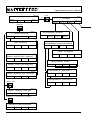
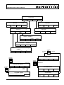
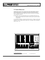
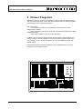
LIGHTCOMMANDER II 24/6
LIGHTCOMMANDER II 48/6
User´s Manual
Version 2.X
July 1996
Lightcommander II User´s Manual
Table of Contents
0. Introduction ................................................................................... 4
0.1 How to use your Operator´s Manual .......................................................... 4
0.2 Specifications and Installation ................................................................... 5
0.3 Display and Top Menu .............................................................................. 5
1. Single Channels ............................................................................ 8
1.1 Presets and Masters ................................................................................. 8
1.2 Add - Swop Buttons ................................................................................... 8
1.3 Extra Channels (AUX 1-6) ......................................................................... 9
2. Preprogrammed Pictures (Memories) ......................................... 10
2.1 Memory Pages ........................................................................................ 10
2.2 Programming Memories .......................................................................... 11
2.3 Switch Memories ..................................................................................... 12
3. Chaser Programs ........................................................................ 13
3.1 Programming ON-OFF Chases ............................................................... 14
3.2 Programming Real-Level Chases ........................................................... 15
3.3 Programming Memory Chases ............................................................... 15
3.4 Recalling a Chase ................................................................................... 16
3.5 Controlling the Speed of a Running Chase ............................................. 16
3.6 Controlling the Fade between Chase Steps ............................................ 17
3.7 Chases on Memory Faders ..................................................................... 18
4. Dipless Crossfade (X-Fade) ....................................................... 19
4.1 Automatic Crossfade between Memories ................................................ 20
4.2 Manual Crossfades between Memories .................................................. 21
4.3 X-Fading a Chaser Program ................................................................... 22
5. Preprogrammed Lighting Shows (Sequences) ............................ 23
5.1 Programming Sequences ........................................................................ 23
5.2 Recalling Sequences .............................................................................. 24
2
MA Lighting Technology GmbH Höhenweg 6 D-97249 Eisingen Tel.:(49)-9306-2459
Lightcommander II User´s Manual
6. Preview and Modifying ................................................................ 25
6.1 BLIND Function ....................................................................................... 25
6.2 PREVIEW - Output Listing ...................................................................... 25
6.3 Output Limit ............................................................................................ 26
6.4 Previewing and Modification of Memories .............................................. 27
6.5 Modifying Chase or Sequence Steps ...................................................... 28
6.6 Previewing a Chase ................................................................................ 29
6.6.1 Preview at the Chaser Section ......................................................... 29
6.6.2 Preview a Chase on Memory ........................................................... 29
6.6.3 Previewing a Chase linked to a Sequence Step .............................. 29
6.7 Preview and Modifying a running X-Fade ............................................... 30
6.7.1 Preview on the following X-fade Steps ............................................ 30
6.7.2 Modifying X-Fade Steps ................................................................... 31
6.7.3 Changing X-Fade Scene Order ........................................................ 32
7. Special Functions ........................................................................ 33
7.1 Single Channel Setups ............................................................................ 33
7.1.1 Doubling the Channel Number (WIDE Function) ............................. 33
7.1.2 Connection Desk Channel to Dimmer Channel (Softpatch) ............. 34
7.1.3 Dimmer Curve.................................................................................. 35
7.1.4 Swop Disable .................................................................................. 35
7.2 Changing Board Operation Mode............................................................ 36
7.2.1 Switch Memories .............................................................................. 36
7.2.2 Keyswitch ......................................................................................... 36
7.2.3 Theatre Sequence ............................................................................ 37
7.3 Backup on Cue Cards ............................................................................. 38
7.4 CLEAR ALL Programs on the Desk ....................................................... 38
7.5 Automatic Test Routines ........................................................................ 38
7.6 Adjusting Date And Time ....................................................................... 38
7.7 HOLD Function ...................................................................................... 39
8. Remote Control and Linking........................................................ 39
8.1 Master-Slave Operation .......................................................................... 39
8.2 MIDI Functions ........................................................................................ 40
9. Input and Output ......................................................................... 42
Index ............................................................................................... 43
Safety instructions ........................................................................... 46
Declaration of conformity ................................................................ 47
MA Lighting Technology GmbH Höhenweg 6 D-97249 Eisingen Tel.:(49)-9306-2459
3
Lightcommander II User´s Manual
0. Introduction
The MA Lightcommander II has been recognized for years as one of the
best and most reliable boards for medium size show and high quality
productions. With our new software 2.X, which is available since January
1994 and can also be installed in all older boards, we enable the Lightcommander II to perform numerous new functions. One of them, the WideMode, doubles the number of usable channels, other functions will make
the board even more user friendly.
0.1 How to use your Operator´s Manual
The first chapters of this manual will introduce you to the basic functions
of the Lightcommander II. The bottom line always indicates special functions on that subject. The graphic shows the described part of the board,
or the contents of the display.
Chapters 6 to 8 describes the numerous special functions, the different
display menus as well as the possibility of synchronizing the MA Lightcommander II via MIDI or couple two boards in master-slave mode.
Chapter 9 deals with the inputs and outputs on the backpanel of the MA
Lightcommander.
The index in chapter 10 allows you to locate special subjects.
Lightcommander II 24/6
4
MA Lighting Technology GmbH Höhenweg 6 D-97249 Eisingen Tel.:(49)-9306-2459
Lightcommander II User´s Manual
0.2 Specifications and Installation
The MA Lightcommander II is available in two versions: 24/6 and 48/6.
Both versions have a 100 - 240 Volt AC input on the back panel.
The signal outputs to your dimmers are: DMX 512 (1990) and 30 / 54
channel analog via Socapex EF337.
Apart from the different numbers of channels, the two boards perform the
same functions.
0.3 Display and Top Menu
The build-in LCD display informs you on the present program and in
conjunction with the 4 buttons located directly below the display you have
access to numerous special functions. The QUIT button always brings the
board back to the Top Menu (shown below).
The specific functions of the 4 buttons are always described in the boxes
of the display directly above them.
The Encoder wheel on the right of the display is used for data-input in
conjunction with special functions shown in the display. All values and data
that can be altered or changed by the Encoder wheel are always displayed
in front of a dark background.
The following page lists all displays of the Lightcommander II. The page
where to find the exact descriptions of the specific display and its functions is shown above the graphic.
TOP MENU - accessible via QUIT button
X-Fade program
see 4.3
Real time
clock see
7.6
Chaser program s.3
M A - LIGHTCOMMANDER 24/6
--
--
PROGRAM
MEMORY
Programming of
stage scenes
12 : 07 : 13
PRG CHASE
SEQUENCE
see
3. Chaser
programs,
5. Sequences
CHASE TO
MEMORY
see
3.7 Chaser on
Memory-faders
V.2.X
01 -UTILITY
SETUP
see 7. Special
functions.
MA Lighting Technology GmbH Höhenweg 6 D-97249 Eisingen Tel.:(49)-9306-2459
5
Lightcommander II User´s Manual
QUIT
Page 39
HOLD
Page 5
> 1sec
HOLD
TOP MENU
HOLD
OFF
PROGRAM PRG CHASE CHASE TO
MEMORY SEQUENCE MEMORY
UTILITY
SETUP
PREVIEW
Page 25
OUTPUT MONITOR
LIMIT
SELECT MEMORY
X-FADE
Page 11
PROGRAMMING MEMORY
QUIT
DISPLAY
MEMORY
SAVE
OUTPUT
SAVE
PRESET 2
Page 26
LIMIT MONITOR
100 %
0 % OFF
Page 14/23
PROGRAMMING CHASE-SEQUENCE
ALL 100 %
EDIT
DELETE
CHASE
SEQUENCE
Page 18
CHASE TO MEMORY
Page 31
LEARN
SPEED
DELETE
SOUND
MODIFY ON/OFF STEP GRAPHIC
STEP 07
Page 14/28
PROGRAMMING CHASE
Page 31
MODIFY LEVEL STEP MONITOR
STEP 06
ENTER
DELETE
INSERT
COPY
CHASE -Page 23/28
Page 31
MODIFY MEMORY STEP MONITOR
STEP 03
MODIFY
MEM 6 A
PROGRAMMING SEQUENCE 1
ENTER
DELETE
INSERT
COPY
CHASE -Page 23
PROGRAMMING SEQUENCE 2
MEMORY button
ENTER
INFADE
OUTFADE
LINK
Page 27
MODIFY MEMORY MONITOR
MODIFY MEMORY:
5 A
MEMORY 13-16, in case of Chase on Memory
Page 29
PREVIEW CHASE IN MEMORY
LEARN
6
STEP
SOUND
MA Lighting Technology GmbH Höhenweg 6 D-97249 Eisingen Tel.:(49)-9306-2459
Lightcommander II User´s Manual
Page 33-40
UTILITIES
SETUP
WIDE
SWITCH
MEMORY
PATCH
BACKUP
Page 38
BACKUP
SAVE
LOAD
FROM CARD TO CARD
THEATRE
SEQUENCE
EXCHANGE
MEMORY
Page 39-40
Page 3435
OUTPUT
CURVE
EXTERN
Page
33,36,38
SETUP
CLOCK
OUTPUT
EXTERN
SWOP DISABLE
MIDI IN
MIDI OUT
ALT:CTRL.
SLAVE
Page 35
SWOP DISABLE
ENABLE
ALL
DISABLE
ALL
Page 34
OUTPUT - PATCH
CONNECT
OPEN
1 : 1
CLEAR
Page 35
CURVE
ALL
LINEAR
X-FADE
on/off
ALL
CURVE
X-FADE
off
X-FADE
on
Page 19-24,32
X-FADE PLAY
CHASER
NUMBER
X-FADE
MENU
Page 16/29
OUTFADE
INFADE
NEXT
MANUAL
toggles between menus
CHASER NUMBER
CHASER
SPEED
PREVIEW
STEP
SPEED
new selected
Chase
running
Chase
Page 19-24
X-FADE SETUP
SELECT
Page 16-17
SINGLE
RUN
SWAP
REC.FADE
Page 32
X-FADE OFF
CHASER SPEED
FADETIME REVERSE
LEARN
SOUND
SELECT
FADE
OFF
GO -
SWITCH
OFF
MA Lighting Technology GmbH Höhenweg 6 D-97249 Eisingen Tel.:(49)-9306-2459
7
Lightcommander II User´s Manual
1. Single Channels
1.1 Presets and Masters
There are two sets of faders (Preset 1 and 2) and one set of flash buttons
to control the single channels.
The Main Master controls the output and should be at 100% during standard operations.
Adjustments on the Presets can be faded in and out independently using
the two Preset Master faders.
The LED´ at the single channel buttons show the actual intensity of the
channel, but will change during Preview, Programming and Blackout
operations.
The Blackout button (DBO) underneath the Main Master fader will clear
the complete output, while the LED´s will still inform about the intensity
which comes up as soon as the button is released (exceptions: see 1.3
AUX Channels and 7.2.1 Switch Memories)
1.2 Add - Swop Buttons
The buttons will switch on the channel. The brightness of this effect can
only be reduced by the Main Master.
If the SWOP function is switched on (LED in the SWOP button lits up),
each press of a button will erase all other channels but the selected one
(Solo effect).
Preset 1
faders
Preset 2
faders
Single
channel
buttons
SWOPbutton
For further informations see:
Doubling the number of channels
Changing the channel order
Locking single channels against SWOP effect
8
MainMaster
PresetMaster 1
and 2
- 7.1.1 WIDE Function
- 7.1.2 Softpatch
- 7.1.4 Swop Disable
MA Lighting Technology GmbH Höhenweg 6 D-97249 Eisingen Tel.:(49)-9306-2459
Lightcommander II User´s Manual
1.3 Extra Channels (AUX 1-6)
Beside the 24 rsp. 48 channels of the presets the Lightcommander II offers
six additional channels via the potentiometers AUX 1 to AUX 6. Adjustments on this pots are independent from the Main Master, Blackout button
or Preset Masters and are specially designed for the control of colour
changers or other stage effects.
(As a part of preprogrammed stage scenes like memories or chases this
AUX channels can also be mastered with the according fader)
AUX 1-6
For further informations see:
Colour changers in memories
- 2.3 and 7.2.1 Switch Memories
MA Lighting Technology GmbH Höhenweg 6 D-97249 Eisingen Tel.:(49)-9306-2459
9
Lightcommander II User´s Manual
2. Preprogrammed Pictures (Memories)
Adjusted stage scenes can be stored as Memories. Sixteen Memory
Master faders with flash buttons offer control of this pictures.
If the SWOP function is switched on, pressing a memory button will recall
this picture and erase all other channels or memories on stage.
2.1 Memory Pages
Each of the 16 Memory faders can carry up to eight different pictures.
The page buttons A to H preselect, which of this eight pictures is actually
programmed or recalled.
As long as a Memory fader is pulled up, it will not be affected by changing
the page selection. It will stay with its picture until it is returned to zero.
Coming up again it recalls the picture on the newly selected page.
As long as one or more Memory faders are still working with an old page
selection, the LED in the new page will flash.
For further informations see:
Chase effects on Memory faders
Dipless crossfade between Memories
10
- 3.7 Chase on Memory
- 4. X-Fade
MA Lighting Technology GmbH Höhenweg 6 D-97249 Eisingen Tel.:(49)-9306-2459
Lightcommander II User´s Manual
2.2 Programming Memories
Programming Memories is guided by menus of the build-in LCD display.
Operation mode:
1.
Adjust stage scene via Preset faders or by recalling preprogrammed
memories.
2.
PROGRAM
MEMORY
3.
Selection of one of the Memory buttons.
4.
SAVE
OUTPUT
5.
The QUIT button switches back to the TOP MENU.
1-5
The first red button underneath the display
switches the menu to
"PROGRAMMING - MEMORY".
The 3. display button of the menu
"PROGRAMMING MEMORY"
saves the actual stage scene under the preselected Memory number.
Quick programming mode:
Keeping "PROGRAM MEMORY" button pressed and selecting a
Memory Flash button stores the actual output as Memory.
MENU "PROGRAMMING - MEMORY"
Number and page of the
selected Memory.
- accessible via the TOP MENU
Number and page of the
memory, programmed last.
Percent of the storage
capacity, still available.
PROGRAMMING - MEMORY
MEMORY
LAST
QUIT
Returns to the
TOP MENU
---
A
A
DISPLAY
MEMORY
Shows the old
Memory of the
selected address.
For further informations see:
Preview and modify memories
Blind Programming
FREE: 95.72 %
SAVE
OUTPUT
Stores the
output as
Memory.
SAVE
PRESET 2
Stores only the adjustment on
Preset 2, regardless the
position of the Preset or Main
Master, as Memory.
- 6.4 PREVIEW
- 6.1 BLIND function
MA Lighting Technology GmbH Höhenweg 6 D-97249 Eisingen Tel.:(49)-9306-2459
11
Lightcommander II User´s Manual
2.3 Switch Memories
Additional 64 pictures can be stored onto the 8 Switch Memory buttons.
Via the page selection it is possible to store and recall 8 pictures per
button. Programming switch Memories works the same way as programming standard memories.
FLASH Mode: Like the Flash buttons of the 16 standard memories, the
Switch Memory buttons will recall the memory as long as the button
is held down.
It is optionally possible to change the Flash mode to a Toggle or Kill mode
between on and off (particularly useful when controlling colour changers or
effects, see 7.2.1).
For further informations see:
Changing the Flash mode to Toggle or Kill mode
12
- 7.2.1 Special Memories
MA Lighting Technology GmbH Höhenweg 6 D-97249 Eisingen Tel.:(49)-9306-2459
Lightcommander II User´s Manual
3. Chaser Programs
Beside the static memories it is possible to store up to 50 chaser effects
with up to 99 steps each. There are three different kind of chase programs
regarding the way of setting the steps:
ON-OFF Chase:
on each step a selection of channels is switched on to 100%.
REAL-LEVEL Chase:
the brightness of the single channels can be freely adjusted per step.
MEMORY Chase:
each step recalls one of the stored memories.
Chases can be recalled via the special chaser section right hand on the
master board or can be loaded to one of the memory master faders 13 to
16. This way up to 5 chaser programs can run simultaneously with individual speed.
Slow fades between the single steps are only possible when running a
program on the chaser section.
MA Lighting Technology GmbH Höhenweg 6 D-97249 Eisingen Tel.:(49)-9306-2459
13
Lightcommander II User´s Manual
3.1 Programming ON-OFF Chases
All chaser programs have to be stored step by step.
1.
2.
PRG CHASE/
SEQUENCE
Selecting a program
number via the Encoder
wheel.
The second display button on Top Menu
switches to
"PROGRAMMING CHASE-SEQUENCE"
3.
CHASE button. Selecting the chase
mode. The box in front of ON/OFF has
to be marked.
PROGRAMMING - CHASE-SEQUENCE
01
MEMORY
ON/OFF
LEVEL
STEPS: 01
FREE: 95.72 %
EDIT
4.
DELETE
CHASE
MEMORY
LEVEL
SEQUENCE
EDIT button: leads to programming the single steps.
The LED´s within the single channel buttons no longer display the output but will only show the
setting of the actual step. To see the steps on stage, the BLIND button right underneath the
display has to be switched off.
5.
The Flash buttons select channels to be full on for the
..... actual step. AUX-channels can be selected by turning
the potentiometer.
Number of actual step can be selected via
encoder wheel
Total number of steps already
programmed
PROGRAMMING - CHASE
No. 01
ON/OFF CHASE ( USE CHANNEL BUTTON )
FREE: 95.72 %
STEP
02
STEPS: 01
ENTER
DELETE
INSERT
COPY
see 6.5 Modification of
chaser programs
14
6.
ENTER: Stores the channel selection as one step of the chaser program.
Going on with setting channels and Enter will add additional steps.
7.
The QUIT button switches back to the TOP MENU.
MA Lighting Technology GmbH Höhenweg 6 D-97249 Eisingen Tel.:(49)-9306-2459
Lightcommander II User´s Manual
3.2 Programming Real-Level Chases
On Real-Level Chases the single channels can have freely adjusted
values for each step. Programming works like with the ON-OFF chases
but LEVEL has to be selected via the CHASE button.
If the selected program number was already used by any other chase,
changing the chase mode to LEVEL will clear the old program. If the mode
was changed accidentally, selecting the "NO" button will cancel the operation and keep the old program.
1.
2.
3.
4.
.........
.........
MEMORY
ON/OFF
LEVEL
Selecting "LEVEL"
.........
CHASE
MEMORY
LEVEL
SEQUENCE
5.
The brightness of the single channels can be set by the
Preset 2 faders. Again ENTER will store the steps.
6.
7.
3.3 Programming Memory Chases
Already programmed memories can be linked together to run as a chase.
1.
2.
3.
.........
.........
4.
.........
5.
MEMORY
ON/OFF
LEVEL
Selecting "MEMORY"
CHASE
...
MEMORY
LEVEL
SEQUENCE
The memories are selected via their Flash buttons.
The number and page is shown in the display.
6.
7.
For further informations see:
Explanations on the display
Test and modification of stored chaser programs
- s.6.5
- s.6.5 and 6.7
MA Lighting Technology GmbH Höhenweg 6 D-97249 Eisingen Tel.:(49)-9306-2459
15
Lightcommander II User´s Manual
3.4 Recalling a Chase
Chases can be controlled via the special chaser section right hand of the
main master fader.
"Number"-button
The upper section of the display shows program number and
step of the actually running chaser program. Via the Encoder a
new program number can be preselected as NEXT :....
"ON"-button
starts the "NEXT" chaser program.
"OFF"-button
stops the actual chase.
The brightness of this chaser effect can be mastered by the chaser master
fader.
3.5 Controlling the Speed of a Running Chase
"Speed" button within the Chaser section
switches to the "CHASER SPEED" menu.
The rate of the chaser is shown in Hertz (steps per second)
and as real step time in seconds. It can be set via the Encoder
or by the LEARN button.
CHASER SPEED
2.12
0.47
Hz
FADE
No. 01
00%
Sec
FADETIME
LEARN
Direct input of the
chaser speed by
pushing the button
in time to the
music.
RUN: 0.00 Sec
SOUND/MANUAL: 0.00 Sec
REVERSE
SOUND
Incoming
sound triggers
the chase
SINGLE
FREE RUN
SWAP
Chase runs with adjusted
speed. Without FREE
RUN or SOUND selected,
only the STEP button will
switch the chase to the
next step.
Alters the function
of the display
buttons to FADETIME - REVERSE SINGLE.
The adjusted speed, the mode and the fadetime is stored together with the
chase number.
16
MA Lighting Technology GmbH Höhenweg 6 D-97249 Eisingen Tel.:(49)-9306-2459
Lightcommander II User´s Manual
3.6 Controlling the Fade between Chase Steps
The change between steps of a chase can be preformed as switching to
the new values or as a slow fade. The fade functions gets activated by the
FADE button in the chaser section.
On the Lightcommander II any fade will work as a dipless crossfade. A
single channel i.e., which is at 100% in the first and at 80% in the second
step, will not fade down and come up again, but will fade linearly from 100
to 80%.
The speed of the crossfade is set in the Speed Menu.
1.
2.
3.
4.
"Speed" button at the chaser section
switches to the menu "CHASER SPEED"
4. Display button SWAP
SWAP
Changes the function of the display buttons to
control the FADETIME and the running direction.
As long as the FADETIME button is pushed,
the Encoder can be used to set the time.
FADETIME
Fadetime in percent of the
step time (for FREE RUN
mode only)
Real fadetime in
seconds
CHASER SPEED
2.12
0.47
Hz
FADE
No. 01
50%
Sec
LEARN
FADETIME
As long as button is
pushed, the Encoder
can be used to set the
fadetime.
Fadetime for STEP
button mode or
SOUND control
SOUND
REVERSE
Inverts the
running
direction
RUN: 0.23 Sec
SOUND/MANUAL: 0.00 Sec
FREE RUN
SINGLE
Chaser will stop
with the last step
SWAP
Changes the
function of the
display buttons
When using FREE RUN mode, the Fadetime gets adjusted in percent of
the step time. Changing the speed of the chase will automatically adapt
the fadetime.
In case FREE RUN is switched off and the steps are recalled by sound
signal or the Step button, the fadetime is set in seconds.
MA Lighting Technology GmbH Höhenweg 6 D-97249 Eisingen Tel.:(49)-9306-2459
17
Lightcommander II User´s Manual
3.7 Chases on Memory Faders
The four memory faders 13-16 can be used to recall chases. One single
program may even be recalled several times with different speed. The
actual chaser speed is indicated by the LED in the memory button.
1.
CHASE TO
MEMORY
2.
Selection of one of the Memories 13-16 by its Flash button.
The display shows, whether there is already a chase linked to
this memory.
The 3.Display button at the Top Menu
switches to "CHASE TO MEMORY".
CHASE TO MEMORY
MEMORY
SPEED:
LEARN
Direct input of the
speed by pushing
the button in time
to the music.
3.
4.
5.
18
13
A
CHASE No.
3.22 Hz
0.31 Sec
SPEED
While SPEED button is
pressed, the Encoder
changes the speed.
STEPS:
TYPE:
DELETE
01
12
ON/OFF
SOUND
Clears the link and
the fader will return to
control the static
memory.
Incoming sound
signal triggers the
chase.
Using the Encoder will select a chaser program number.
The channel LED´s show the chase running with the selected
speed.
While the SPEED button is pressed, the Encoder changes the
chaser speed.
Quit returns the desk to the Top Menu.
MA Lighting Technology GmbH Höhenweg 6 D-97249 Eisingen Tel.:(49)-9306-2459
Lightcommander II User´s Manual
4. Dipless Crossfade (X-Fade)
Right hand of the memory master faders the Lightcommander offers a
special X-Fade section for dipless crossfades between stage scenes.
Unlike the effect of changing from one memory to another by moving up or
down the faders, on dipless X-fades any channel changes linearly to its
new value.
Selecting the working mode (SETUP)
At the setup it can be chosen whether the scenes get selected by their
buttons or whether the X-Fade runs one of the stored programs.
2 x pressing the "X-Fade menu" button underneath the QUIT
button switches the board to the X-Fade Setup Menu.
Number, length and type of the selected program
X - FADE SETUP
DIRECT
MEMORY
PREPARE
MEMORY
MEMORY
- - - - STEPS
CHASE
TYP:
-------SEQUENCE
TIMED SEQUENCE
SELECT
SELECT
"DIRECT": selecting a memory
by its button starts the X-fade
immediately.
"PREPARE": the X-fade will not
start before the GO button is
pressed
REC.FADE
Selection of
the working
mode
Stores the adjusted fade
time per steps rsp. times
the manual fade
X-fade working menu:
"X-Fade On/Off" button starts the X-fade mode. If the X-fade
is already on, the "X-fade Menu" button toggles between the
two menus.
Actual stage
scene
New picture, ready to
fade in
X - FADE
MEMORY
-- A
-- A
2.25
2.25
OUTFADE
Outfade time of the
actual scene
Next picture, if
already prepared
INFADE
Infade time of the
new picture
NEXT:
-- A
NEXT
s.6.7 Changing the
order of preprogrammed
X-fade shows
MANUAL
Toggles between automatic and manual fade
Terminating the X-fade mode:
As long as the "X-Fade On/Off" button is held down, the
display offers two new functions.
FADE OFF: the next fade will clear the X-fade
SWITCH OFF: terminates the X-fade mode immediately
MA Lighting Technology GmbH Höhenweg 6 D-97249 Eisingen Tel.:(49)-9306-2459
19
Lightcommander II User´s Manual
4.1 Automatic Crossfade between Memories
1.
2 x "X-Fade Menu" button switches to the Setup.
X - FADE SETUP
DIRECT
MEMORY
PREPARE
MEMORY
SELECT
SELECT
REC.FADE
2.
Select "DIRECT MEMORY" and "MEMORY" via the first two
display buttons
3.
"X-Fade On/Off" button starts the X-fade mode
X - FADE
-- A
2.25
2.25
Outfade time of the
actual stage scene
4.
5.
6.
MEMORY
-- A
OUTFADE
20
MEMORY
- - - - STEPS
CHASE
TYP: - - - - - - - SEQUENCE
TIMED SEQUENCE
NEXT:
INFADE
Infade time of the
new picture
-- A
MANUAL
S. 4.2 (has to be
switched off)
Times, selected by the display button, are displayed on black
background and can be altered via encoder or the fader
in the X-fade section. The fader works in grap mode,
e.g. as soon as it reaches the actual value, it will take
over control
When recalling memories by their buttons, the desk will fade
to the new picture. Even during running fades the times can
still be modified.
While the "X-Fade On/Off" button is held down, the X-fade
mode can be terminated by the display buttons SWITCH OFF
or FADE OFF.
MA Lighting Technology GmbH Höhenweg 6 D-97249 Eisingen Tel.:(49)-9306-2459
Lightcommander II User´s Manual
4.2 Manual Crossfades between Memories
Instead of fading automatically with adjusted times it is possible to fade
manually by moving the X-fader
1.
2.
3.
3a.
...
... like on automatic mode
...
Selecting MANUAL (4th display button)
X - FADE
MEMORY
04 A
09 A
NEXT:
2.25
2.25
* MOVE FADER *
OUTFADE
INFADE
Without any function Without any function
on manual mode
on manual mode
06 A
MANUAL
Selected for manual X-fades
4.
Memories get selected by their flash buttons and displayed as
NEXT: ...
5.
Starting from the lower or upper end of the travel, the
crossfade can be done manually via the X-fader.
As soon as the end of the travel is reached, NEXT will be
loaded to be the INFADE.
The NEXT memory can already be selected before the last fade was
finished. The preselected memory will automatically be downloaded at the
end of the travel.
6.
Holding "X-Fade On/Off" down and selecting SWITCH OFF in
the display terminates the X-Fade. After FADE OFF the next
fader travel will manually fade off.
For further informations see:
X-Fade with preprogrammed scene order
-
5. Sequences
MA Lighting Technology GmbH Höhenweg 6 D-97249 Eisingen Tel.:(49)-9306-2459
21
Lightcommander II User´s Manual
4.3 X-Fading a Chaser Program
The steps of any chase can be recalled on the sequence section. Adjusting
fade times or fading manually works similar like on selecting the scenes
via the memory buttons.
The LED within the GO button lites as long as the X-fade runs. After
finishing the fading the LED goes out.
1.
2 x "X-Fade Menu" button
X - FADE SETUP
DIRECT
MEMORY
PREPARE
MEMORY
MEMORY
01 06 STEPS
CHASE
TYP:
ON / OFF
SEQUENCE
TIMED SEQUENCE
SELECT
SELECT
REC.FADE
2a.
2b.
Selecting
"CHASE"
3.
Selecting a chase
program number
via encoder
"X-Fade On/Off" button starts the X-fade mode
X - FADE
CHASE
02
03
2.25
2.25
OUTFADE
Outfade time of the
actual scene
INFADE
NEXT
Infade time of the
new picture
Automatic mode:
The GO button
starts the X-fade
with adjusted times
4a.
NEXT:
4b.
03
STEP:
03 (06)
MANUAL
Toggles to manual
fade mode
Manual mode:
By moving up and
down the fader the
scenes are recalled
manually
Go
For further informations see:
Inserting a memory within the chaser steps
Returning to the last step
22
- 6.7.3 Modifications of step order
- 6.7.3
MA Lighting Technology GmbH Höhenweg 6 D-97249 Eisingen Tel.:(49)-9306-2459
Lightcommander II User´s Manual
5. Preprogrammed Lighting Shows
(Sequences)
Beside the chaser programs there are another 50 sequence programs to
be stored and recalled on the X-fade section exclusively. Compared to the
chaser programs this sequences may have preprogrammed times per step
and may recall a chase as one of the steps.
5.1 Programming Sequences
1.
2.
PRG CHASE
SEQUENCE
The menu allows to select another 50 program
numbers marked as sequences.
Selecting SEQUENCE and a program number. Analog to programming
chasers, MEMORY and REAL LEVEL sequences are selectable.
PROGRAMMING CHASE - SEQUENCE
01
MEMORY
ON/OFF
LEVEL
STEPS: 00
FREE: 95.72 %
EDIT
3.
4.
DELETE
CHASE
MEMORY
LEVEL
SEQUENCE
EDIT leads on to programming the single steps.
Depending on the selected type the steps are created by selecting a
memory or preparing the scene with the preset 2 faders.
PROGRAMMING - SEQUENCE
USE PRESET 2
STEP
FREE: 95.72 %
STEPS: 00
OUTFADE 0.50 SEC
01
INFADE 0.50 SEC
ENTER
5.
DELETE
INSERT
COPY
ENTER stores the step and toggles to the second menu.
PROGRAMMING - SEQUENCE
STEP 01
ENTER
6. Fade
No. 01
1.75
1.00
Sec
Sec
CHASE 06
LINKED
INFADE
OUTFADE
LINK
times can be selected via their button and
adjusted by the encoder.
8.
No. 01
7. As
long the LINK button is held
down, the encoder sets a chaser
program number.
Turning to "0" unlinks the chase.
ENTER stores the fade times and the linked chase and goes on to programming the next step.
For further informations see:
Including memories as Real Level Step- 6.5 Modifying chaser or sequence steps
Saving the output as Real Level Step - 6.5
Working with Theatre Sequence
- 7.2.3
MA Lighting Technology GmbH Höhenweg 6 D-97249 Eisingen Tel.:(49)-9306-2459
23
Lightcommander II User´s Manual
5.2 Recalling Sequences
2 x "X-Fade Menu" button.
1.
2a.
Selection of SEQUENCE (preprogrammed times get ignored) or TIMED
SEQUENCE (program will recall the preprogrammed fade times)
2b.
Selecting a sequence program number via encoder.
X - FADE SETUP
DIRECT
MEMORY
PREPARE
MEMORY
SELECT
SELECT
REC.FADE
"X-Fade On/Off" button start the X-fade mode.
3.
X - FADE
Go
TIMED SEQUENCE
01
02
1.00
2.25
OUTFADE
4a.
MEMORY
01 06 STEPS
CHASE
TYP: ON / OFF
SEQUENCE
TIMED SEQUENCE
INFADE
No. 01
STEP:
03 (06)
CHASE 01 LINKED
NEXT:
NEXT
02
MANUAL
The sequence can be recalled manually via the fader or
automatically via the GO button. If TIMED SEQUENCE was
selected, the preprogrammed fade times get recalled for
each step, but can still be modified.
A chase, linked to a sequence step, will be listed in the display before it
starts. As soon as the sequence step starts, the board cancels the chase,
which is actually running at the chaser section and will load and start the
linked chase. The brightness of the chase is fading in and out together
with the brightness of the sequence step. As long as the sequence controls
the chase, the LED in the chaser ON button blinks. To cancel or control the
chase independently from the sequence step, it has to be restarted with
the ON button. This way the brightness of the chase returns to be controlled via the chase fader.
For further informations see:
Inserting a memory into the sequence step order
Returning to the previous step
Testing and modifying a running sequence
24
- 6.7.3 Modifying the step order
- 6.7.3
- 6.7.1 and 6.7.2
MA Lighting Technology GmbH Höhenweg 6 D-97249 Eisingen Tel.:(49)-9306-2459
Lightcommander II User´s Manual
6. Preview and Modifying
Any program of the Lightcommander can be previewed and modified
before it comes to stage. The actual output values can be listed in percentage and the Limit function enables to reduce the overall brightness of
any channel.
6.1 BLIND Function
During programming, previewing or modifying, the channel LED´s no
longer show the output intensity, but show the contents of the selected
program.
During "PROGRAMMING MEMORY" they show preset 2 intensity only.
This enables to program memories blind by setting the preset 2 master to
zero and selecting "SAVE PRESET 2" for saving the memory.
BLIND button right under the display switched on:
The program, indicated on the LED´s, is not transmitted to
stage.
BLIND button switched off:
The indicated program will be send to stage, even with main
master at zero. During Softpatch operations the selected
dimmer number gets switched on.
If BLIND is switched off, the Top Menu shows a "LIVE" warning.
Recalling the preview function will automatically activate the BLIND
function.
6.2 PREVIEW - Output Listing
ATTENTION !
The PREVIEW button underneath the display lists the actual
output values in percentage. As Preview also starts the testing
of memories, the memory buttons are not longer switching on
the memories but just select them for previewing.
Channel number, A1-A6
indicates the AUX channels
01 - 07 FF 13
02 45 08 FF 14
03 62 09 - 15
04 - 10 12 16
05 - 11 03 17
06 - 12 - 18
LIMIT
See 6.3
Output limit
-
Actual output value
(FF=100%)
19 - 25 - 31 20 - 26 - 32 21 - 27 - 33 22 - 28 - 34 23 - 29 - 35 24 - 30 - 36 SELECT MEMORY
37
38
39
40
41
42
-
43 - A1
44 - A2
45 - A3
46 - A4
47 - A5
48 - A6
X-FADE
-
See 7 preview and modifying
sequence steps
MA Lighting Technology GmbH Höhenweg 6 D-97249 Eisingen Tel.:(49)-9306-2459
25
Lightcommander II User´s Manual
6.3 Output Limit
Press the PREVIEW button
1.
2.
First button toggles to the Limit function.
The LED´s of all channels, which got a
reduction yet, lit up. The display lists the
limitations whereas FF=100% means, that
there is no reduction on this channel.
LIMIT
Channels with numbers displayed on black background can be altered by the encoder or the first two
display buttons
01
02
03
04
05
06
FF 07
- 08
62 09
FF 10
FF 11
FF 12
100 %
Sets all selected
channels to 100%
FF 13
FF 14
FF 15
FF 16
FF 17
FF 18
FF 19 FF 25
FF 20 FF 26
FF 21 87 27
FF 22 87 28
FF 23 87 29
FF 24 FF 30
0 % OFF
FF 31 FF 37
FF 32 FF 38
FF 33 FF 39
FF 34 FF 40
FF 35 FF 41
FF 36 FF 42
ALL 100 %
Clears the output for the
selected channel
FF
FF
FF
FF
FF
FF
43
44
45
46
47
48
FF
FF
FF
FF
FF
FF
A1
A2
A3
A4
A5
A6
FF
FF
FF
FF
FF
FF
Cancels all reductions
for all channels.
Limiting single channels:
3a.
Single channel buttons
3b.
The encoder wheel or one of the first two display
buttons
Selecting of one or more channels. The numbers of these
channels get displayed inverted.
changes all selected channels simultaneously. Limitations
work on line on the actual output.
or:
Single channel faders of preset 2:
The reduction can also be set via the faders of preset 2. The
fader will take over control as soon as it reaches the actual
value (Grap mode). To do a limitation via preset 2 without
effect to the stage the preset 2 master has to be at zero.
4.
26
The PREVIEW or QUIT button returns the board to the Top Menu. Any
limitation gets indicated by the warning "OUTPUT LIMIT".
MA Lighting Technology GmbH Höhenweg 6 D-97249 Eisingen Tel.:(49)-9306-2459
Lightcommander II User´s Manual
6.4 Previewing and Modification of Memories
Previewing a memory:
1.
PREVIEW button
2.
Any memory flash button
The LED´s show the channel values as stored in the
memory. The display lists these values in percentage.
Selected channel with numbers
on black background can be
modified via encoder.
01 - 07 FF 13
02 45 08 FF 14
03 62 09 - 15
04 - 10 12 16
05 - 11 03 17
06 - 12 - 18
-
19
20
21
22
23
24
MODIFY MEMORY:
-
25
26
27
28
29
30
-
31
32
33
34
35
36
5
37
38
39
40
41
42
A
-
43
44
45
46
47
48
-
A1
A2
A3
A4
A5
A6
-
Modifying single channel values during preview:
3a.
Channel button
3b.
Encoder wheel right hand of the display
or:
Faders of preset 2
Selected channels get displayed on black background
Changes all selected channels simultaneously. Any
modification changes the stored memory directly, even if it
actually is on stage.
The channel values of the memory can also be modified via
the faders of preset 2. The fader will start to modify the
channel as soon as it has reached the stored value (Grap
mode). To modify a scene without effect to the stage, the
preset 2 master fader has to be at zero.
4.
ATTENTION!!
PREVIEW or QUIT returns the board to the Top Menu
Any modification changes the stored memory data directly. In case the
memory is active on stage, the modification influences the stage too.
MA Lighting Technology GmbH Höhenweg 6 D-97249 Eisingen Tel.:(49)-9306-2459
27
Lightcommander II User´s Manual
6.5 Modifying Chase or Sequence Steps
-
PRG CHASE SEQUENCE
CHASE or SEQUENCE
Selection of the program number via encoder
EDIT
Selecting of the program like on programming
Turning the encoder recalls the step to be shown on the
LED´s. If BLIND is switched off, the steps can be seen on
stage.
PROGRAMMING - CHASE
No. 01
ON/OFF CHASE ( USE CHANNEL BUTTON )
FREE: 95.72 %
STEP
06
STEPS: 12
ENTER
DELETE
INSERT
COPY STEP
Modifying single steps (Overwrite):
Depending on the type of program the steps get modified via the single
channel buttons (ON/OFF), the preset 2 faders working on Grap Mode
(REAL LEVEL) or the memory flash buttons (MEMORY). ENTER saves the
modified step. Selecting a new step via encoder without using ENTER will
cancel the modification.
Deleting the selected step: -
DELETE button on the display
Creating a new step at the selected step address: - INSERT button
Copying the selected step
- COPY button (all squares are now displayed on black background)
- Selecting a new step address via encoder
- ENTER: Overwrites the selected step by the copy
- INSERT: Inserts the copy at the selected address as a new step
- CANCEL: Clears the copy storage and the desk returns -as also by
ENTER and INSERT- to the starting-point
Transferring the output value to a REAL LEVEL sequence step (not possible within the BLIND mode):
The actual output values of sequences, created by memories, chasers or
preset faders, can be copied as LEVEL step.
- Recalling one or more memories via the fader + pushing the COPY
button transfer the values of the memory together with the values of the
actual step into the copy storage. Every further pushing of the copy
button adds the output to the copy storage.
- ENTER, INSERT, CANCEL see above.
28
MA Lighting Technology GmbH Höhenweg 6 D-97249 Eisingen Tel.:(49)-9306-2459
Lightcommander II User´s Manual
6.6 Previewing a Chase
6.6.1 Preview at the Chaser Section
Chases store the speed and fade time of their last recall. Before starting
with the ON button, the program and its times can be previewed and
modified.
The NUMBER button on the chaser section enables to
preselect a new chaser program number via encoder.
Program
number
Actually
running
chase
Newly
selected
chase
Actual
step
Total number of steps and
program type
CHASE NUMBER
RUNNING:
MANUAL
06 11
STEPS:
TYP:
12
LEVEL
NEXT:
FREE RUN
01 05
STEPS:
TYP:
06
ON / OFF
PREVIEW
STEP
Shows the new
chase on the
LED´s
SPEED
Recalls previewing the next
step in case the chase is not
on FREE RUN mode
Switches to the
SPEED menu for the
new chase
Selecting PREVIEW (displayed on black background) shows the new
chase with its speed on the LED´s. Selecting SPEED enables to change
the speed before starting the chase.
6.6.2 Preview a Chase on Memory
"PREVIEW" button
Flash button of a memory 13-16, which contains a chase. The
chase is shown on the channel LED´s.
PREVIEW
MEMORY
SPEED:
LEARN
Setting the speed by
pushing the button in
time to the music
13
CHASE IN MEMORY
A
3.22 Hz
0.31 Sec
CHASE No.
STEPS:
TYPE:
STEP
Preview of the steps in
case the chase is not on
FREE RUN mode
01
12
ON/OFF
SOUND
Incoming sound will
trigger the chase
The encoder changes the speed of the chase.
6.6.3 Previewing a Chase linked to a Sequence Step
Even chases, linked to a sequence step, can be previewed (see 6.7.1)
MA Lighting Technology GmbH Höhenweg 6 D-97249 Eisingen Tel.:(49)-9306-2459
29
Lightcommander II User´s Manual
6.7 Preview and Modifying a running X-Fade
In case a chase or sequence is loaded to the X-fade section, the actual
and following steps can be previewed and modified.
Beside changing single channels intensity it is possible to change the
order of the scenes or to insert a memory.
6.7.1 Preview on the following X-fade Steps
PREVIEW button
The GO button still recalls the next picture while the display
lists the output values.
05
06
- 11 03 17
- 12 - 18
LIMIT
X-FADE
CHASE -
30
- 23 - 29 - 35 - 41
- 24 - 30 - 36 - 42
SELECT MEMORY
- 47 - A5 - 48 - A6 X-FADE
By selecting the fourth display button, the display
will change to show the values of the actual or
infading step of the X-fade.
If there is a chase linked to one of the steps, the
fourth display button allows to swop to the speed
menu of this chase.
MA Lighting Technology GmbH Höhenweg 6 D-97249 Eisingen Tel.:(49)-9306-2459
Lightcommander II User´s Manual
6.7.2 Modifying X-Fade Steps
By using PREVIEW - X-FADE
be modified for any of the steps.
the intensity of the single channels can
Modifying REAL LEVEL steps:
05 - 11 03 17 - 23
06 - 12 - 18 - 24
STEP 06
- 29
- 30
- 35
- 36
- 41
- 42
- 47 - A5 - 48 - A6 CHASE --
Selecting the step by
pressing the STEP button
and selecting the step via
encoder
Channels, selected by their buttons, can be modified via the encoder or
preset 2 faders may be used in Grap Mode.
Modifying MEMORY steps:
05
06
- 11 03 17 - 23 - 29 - 35 - 41
- 12 - 18 - 24 - 30 - 36 - 42
STEP 03
MODIFY
MEM 3 A
As the modification will not only
affect this step, but will change the
stored memory, MODIFY has to be
switched on first. Modifying works
like on LEVEL steps.
- 47 - A5 - 48 - A6 CHASE --
As long as the MEM... button is
held down, the memory can be
substituted by another memory
number.
Modifying ON/OFF steps:
s. WIDE
function
channel
1-24
PREVIEW
CHASE IN MEMORY
USE CHANNEL - BUTTONS TO MODIFY STEP
STEP 07
channel 25-48
AUX 1-6
ON/OFF steps are displayed by a display graphic and on the channel
LED´s. Modifications can be done using the channel flash buttons.
MA Lighting Technology GmbH Höhenweg 6 D-97249 Eisingen Tel.:(49)-9306-2459
31
Lightcommander II User´s Manual
6.7.3 Changing X-Fade Scene Order
When recalling chase or sequence programs via the X-fade section, the
scenes are recalled step by step as set in the program.
This order can be changed using the NEXT- or the GO-Minus function.
Program type
X - FADE
TIMED SEQUENCE
01
02
1.00
2.25
OUTFADE
Program number
INFADE
No. 01
STEP:
02 (06)
CHASE 01 LINKED
NEXT:
NEXT
02
MANUAL
Informations on linked
chases
NEXT
While holding down the NEXT button a new step
can be selected by using the encoder. The next
fade will go to the newly selected step number.
+
NEXT
Holding down the NEXT button and selecting a
memory button inserts this memory within the
scene following.
+
MEMORY
As long as the "X-Fade On/Off" button is hold down, the
display shows the X-fade Off menu. Number of the step to be
recalled by Go-Minus
X - FADE
OFF
GO TO STEP
FADE
OFF
The next fade
terminates the Xfade mode
GO -
Starts the fade to the
previous step
02
SWITCH
OFF
Switches off the X-fade
mode
The "GO-" button starts the fade to the previous step. (This
only works on automatic mode).
32
MA Lighting Technology GmbH Höhenweg 6 D-97249 Eisingen Tel.:(49)-9306-2459
Lightcommander II User´s Manual
7. Special Functions
The UTILITY/SETUP menus of the Lightcommander offer various special functions and setup facilities.
7.1 Single Channel Setups
7.1.1 Doubling the Channel Number (WIDE Function)
One of the most interesting features of software version 2.X is the possibility to double the number of channels. This way the Lightcommander II 24/
6 offers 24+24+6=54 channels (LC II 48/6: 48+48+6=102). All functions
work as usually, only on using the preset section there are some little
changes.
Switching on the WIDE function:
UTILITY/
SETUP
ATTENTION !
Fourth display button on the Top Menu
SETUP
First display button to select the functions
CLOCK - WIDE - SPECIALS - THEATRESEQ.
WIDE
Selecting WIDE (now displayed on black
background) modifies the operation mode:
Single channel faders
The faders of preset 2 still control the same channels, while the faders of
preset 1 work as an extension of preset 2 and control a second set of
channels.
Preset master brightness
The overall brightness of the adjustment on all preset faders is mastered
by the preset 2 master fader only.
Single channel flash buttons and LED´s:
As there is only one set of buttons and LED´s, only half of the channels
are indicated and possible to access by button at time. The preset 1
master after toggles the buttons between the two sets of channels.
Preset 1 master above 50 %: The buttons indicate and control the upper
channels.
Preset 1 master below 50 %: The buttons indicate and control the lower
set of channels. A double arrow on the right edge of the display shows the
actually selected orientation of the buttons.
Channel value listing during PREVIEW and LIMIT:
The Lightcommander 24/6 shows the second set of channels as channel
number 25 to 48.
The Lightcommander 48/6 shows, depending on the preset 1 master
setting, only the upper or the lower set of channels on display.
Graphics (like on PREVIEW ON/OFF step, SWOP DISABLE or CURVE)
show the complete set of channels.
Internally the WIDE function is always working. Memories or programs, set
up under the wide function, will control the extended channel range even if
the WIDE function was switched off later on.
MA Lighting Technology GmbH Höhenweg 6 D-97249 Eisingen Tel.:(49)-9306-2459
33
Lightcommander II User´s Manual
7.1.2 Connection Desk Channel to Dimmer Channel (Softpatch)
The channels of the Lightcommander represented by the numbers under
the flash buttons can be freely patched to the dimmer channel numbers.
Any desk channel may control several dimmer channels simultaneously
whereas the other way round the dimmer channel can only listen to the
control commands of one single desk channel.
Selecting the patch menu via:
UTILITY/
SETUP
OUTPUT
PATCH
Desk channel, actually
connected to the selected
dimmer number
OUTPUT
2.
Desk
channel
selected by
its button
3.
Select dimmer
number via
encoder
1.
-
PATCH
Dimmer:
Connected
04
Channel:
01
CONNECT
Connects the
selected desk and
dimmer channel
Up to 255 dimmers can be
connected to one desk
channel
04
OPEN
Clears the connection
between the selected
channels
01
-----
------
1 : 1
Connects all desk
channels with the
dimmer channels of
the same number
------
-------
-
------
CLEAR
Clears all patch
connections
1.
Selection of a desk channel by its button. On WIDE mode
preset 1 master toggles between the upper and lower channel
set.
2.
The encoder selects a dimmer number. Maximum
dimmer address on the Lightcommander is 256.
2a.
To identify the dimmer number on stage, the selected
dimmer is set to 80 % if the BLIND function is
switched off.
3.
!
34
CONNECT patches the selected desk channel to the selected
dimmer address. Any former connection of this dimmer is
cancelled automatically.
QUIT returns the desk to the Top Menu.
The Lightcommander 24/6 (48/6) features 0 to +10V DC analog output of
the first 30 (52) dimmer channels on Socapex EF337.
The complete range of dimmer channel 1-256 is available via DMX 512
(1990).
During WIDE operation the patch command "1 : 1" will patch the AUX
channels at the end of the standard channel range (LC24: 49-54, LC48:
97-102).
MA Lighting Technology GmbH Höhenweg 6 D-97249 Eisingen Tel.:(49)-9306-2459
Lightcommander II User´s Manual
7.1.3 Dimmer Curve
Standard dimmerpacks usually show an non-linear increase on brightness
when moving up the channel fader. By choosing a special non-linear
output modulation this effect can be compensated. Therefore all channels
which are supposed to control dimmer channels have to be set to
"CURVE" on the Lightcommanders setup menu.
UTILITY/
SETUP
OUTPUT
CURVE
WIDE channels of the LC 48/6
AUX 1-6
CURVE
channel
1-24
LED OFF = LINEAR
channel
25-48
LED ON = CURVE
ALL
LINEAR
ALL
CURVE
For all channels set to CURVE, the LED will lit up and the graphics show a
bar upward. Changes can be done via the channel buttons.
Color scrollers and effects should be controlled with LINEAR setting.
7.1.4 Swop Disable
When using the SWOP effect (see 1.2), channels which control color
scrollers or effects should not be set to zero. For these channels the Swop
effect can be disabled.
UTILITY/
SETUP
OUTPUT
SWOP
DISABLE
SWOP - DISABLE
LED OFF = ENABLED
LED ON = DISABLED
ALL
ALL
ENABLED
DISABLED
On channels which are protected against the Swop effect the LED is on
and the graphic shows a bar upward. Changes can be done via the channel buttons.
MA Lighting Technology GmbH Höhenweg 6 D-97249 Eisingen Tel.:(49)-9306-2459
35
Lightcommander II User´s Manual
7.2 Changing Board Operation Mode
7.2.1 Switch Memories
Especially for working with color scrollers or multi-functional fixtures it is
possible to change the operation mode of the Switch Memories (see 2.3)
FLASH mode: The memory is on stage as long as the button is held down.
When using with Swop effect all other signals get erased during this time.
TOGGLE mode: The memory gets switched on by pushing the button.
It stays on stage and its LED stays on until the button is pressed a second
time.
The values of these TOGGLE memories are independent from main
master or blackout DBO and are not killed by the SWOP effect.
During X-fade operation mode on memories the TOGGLE memories work
independently. They can be switched on without affecting the running Xfade.
KILL mode: Works as the TOGGLE mode, but selecting a new KILL
memory automatically clears the older one.
The Switch Memory mode gets selected via
UTILITY/
SETUP
SETUP
SWITCH
MEMORY
7.2.2 Keyswitch
All programs within the Lightcommander can be protected against
overwriting or clearing.
36
Key position:
ALL ACCESS
Function
Access to all desk functions
LOCK
PROGRAMMING
All programming functions are locked.
During PREVIEW mode the values can not be
changed. Only the speed parameters of the
chases can be adjusted.
LOCK DESK
The desk does not react to any operation on the
front panel. Running chases or remote programs
via MIDI (see 8.2) go on working.
MA Lighting Technology GmbH Höhenweg 6 D-97249 Eisingen Tel.:(49)-9306-2459
Lightcommander II User´s Manual
7.2.3. Theatre Sequence
There are two special modi for Theatre Sequences available with only a little
difference. In general every sequence receives within both modi a step name
consisting of numbers instead of a step number. This name will be unchanged
while inserting or deleting steps. So step 1. 1 will be created by inserting a new
step between step 1 and 2.
Especially in theatre this is the usual mode to insert or delete additional steps
without changing the whole concept.
The Theatre Mode is selected resp. shifted by pushing
UTILITY/
SETUP
SETUP
THEATRE
SEQUENCE
IMPORTANT !
Selecting this mode all previous sequences were deleted after an additional
enquiry.
Therefore it is absolutely necessary to choose either the theatre sequence or
the "normal" sequence before programming the desk!
At any time it is possible to switch between mode 1 and 2 without data getting
lost. To switch from mode 2 back to mode 1, answer "NO" to the enquiry "are
you sure?". So also the sequences are not lost.
The sequences in mode 1 are programmed in the same way as described in
Chapter 5 (p. 23).
In mode 2 either the actual output (LIVE) or the actual step (BLIND) will be
stored.
Firstly the full step name is given (for example 1.0, 2.0, 3.0...); this name can
later be changed within the second PROGRAMMING SEQUENCE menu (after
pushing ENTER once) after turning off INFADE and OUTFADE.
Without changing the step name there is a standard step distance of 1.0. Therefore nine steps (X.1 to X.9) can be inserted; this is done automatically by INSERT. Because changes can be made only within the previous and following
step, a rising order appears.
MA Lighting Technology GmbH Höhenweg 6 D-97249 Eisingen Tel.:(49)-9306-2459
37
Lightcommander II User´s Manual
7.3 Backup on Cue Cards
The complete programs of the Lightcommander can be saved to cue cards
(ITT CANNON - STAR CARD CSC-0032K-SM-3ll or compatible ones).
UTILITY/
SETUP
BACKUP
Testing the card.
When using a new
card or in case of
empty batteries an
ERROR message will
be displayed
BACKUP
CARD: 01/24/94
20:15:12
MA 48/6
V 2.00
CHECKSUM: OK
R/W - TEST: OK
LOAD
SAVE
FROM CARD TO CARD
Loads data from card and
overwrites data in the desk
IMPORTANT !
Date and time when the card
was programmed last
Saves the data from the
desk to the cue card
EXCHANGE
MEMORY
Exchanges the data
between cue card and
desk
ATTENTION: The cue cards work with a battery which has to be mounted
before the first use. Average lifetime of these batteries is two years. Note
the date of inserting the battery on the backside of the card and exchange
the battery in time, otherwise all programs on card get lost.
Please remove the card from the desk as long as the card is not in use.
7.4 CLEAR ALL Programs on the Desk
When starting with a new show all programs of the Lightcommander can
be cleared completely by one single operation. All four display buttons
have to be held down when switching on the desk. After confirmation by
"YES" the board will clear all programs and special setups and set the
softpatch to "1 : 1".
7.5 Automatic Test Routines
Whenever the Lightcommander is switched on it will test all programs and
settings. In case there is any memory error, the according section of data
has to be cleared by the QUIT button. If this happens repeatedly please
contact your MA dealer.
7.6 Adjusting Date And Time
UTILITY/
SETUP
SETUP
38
Within the setup menu time and date can
be adjusted via encoder
MA Lighting Technology GmbH Höhenweg 6 D-97249 Eisingen Tel.:(49)-9306-2459
Lightcommander II User´s Manual
7.7 HOLD Function
The HOLD function will freeze the output of the desk. Changes can then be
made on the desk without those changes occuring on the stage. When
ready, those changes can be output from the desk by reducing the main
master to 0, and than back to 100 %.
Select the HOLD menu by pressing and holding the QUIT
button
HOLD
The HOLD button freezes the output.
Now all changes on the desk can be made "invisibly". When you are ready,
the new stage scene can be faded in using the main master fader which
simultaniously deactivates the HOLD function.
By the HOLD OFF button the HOLD
HOLD OFF
function is deactivated immediately.
8. Remote Control and Linking
Via MIDI two Lightcommander II desks can be linked in master-slave
operation or a show can be recorded to a MIDI sequencer.
8.1 Master-Slave Operation
On the Master desk all functions will work as usual. On the slave desk only
the single channel faders and buttons work. All other functions of the slave
are remote controlled by the master desk. Each desk keeps its own output
on Socapex and DMX 512. The softpatch is done on both boards separately. To send the control data of both desks to stage on one single DMX
cable, the two lines have to be combined via a separate unit, called DMX
Merger.
For working with Theatre Sequences, master and slave desks must be set
to the same mode before coupling!
1.
2.
Switch OFF both desks via the power switch.
3.
Switch on the slave desk first and select
MIDI OUT of the first desk has to be connected to MIDI IN of the second
desk and vice versa. A standard MIDI 5pin cable can be used.
UTILITY/
SETUP
EXTERN
SLAVE
The display stops at "Searching for Master"
4.
Switching on the master desk
starts the communication between the two desks. To allow
synchronous operation, the chaser and sequence programs of the
Slave desk will be cut down or extended to the step number found in
the master board.
5.
The master desk always has to be switched OFF and ON last.
MA Lighting Technology GmbH Höhenweg 6 D-97249 Eisingen Tel.:(49)-9306-2459
39
Lightcommander II User´s Manual
8.2 MIDI Functions
The course of a lighting show can be recorded to a MIDI Sequencer and
played back later on.
MIDI can also be used to link more than two desks by using the MIDI
THRU connector. Compared to the real Master-Slave operation (see 8.1)
there are some limitations on using MIDI.
Recording a show to a MIDI Sequencer:
1.
MIDI OUT of the Lightcommander has to be connected to the Sequencer
input.
2.
UTILITY/
SETUP
EXTERN
Selecting of the EXTERN Menu
3.
MIDI CHANNEL
4.
Switch on RECORD mode at the sequencer
5.
6.
Selecting a MIDI channel 1 to 16
06
MIDI OUT
Switch on MIDI OUT at the Lightcommander
QUIT returns the desk to the Top Menu.
Because of the limited speed of the MIDI protocol there are some restrictions to the use of the desk while sending MIDI data;
- Single channels are not recorded on MIDI.
- The X-fade can only be used in automatic mode on timed sequences and
times can not be changed on-line.
Playback of a MIDI show
1.
2.
3.
40
MIDI IN of the Lightcommander has to be connected to the output of the
sequencer.
MIDI IN
Selection of the MIDI channel. MIDI IN has to be switched on.
Start the Sequencer.
During playback it is still possible to use the memories or channels of the
board. When using the chaser or X-fade section the manual operation will
overwrite and cancel the MIDI controlled program (Chaser ON or GO LED
is flashing as long as MIDI uses the according section). During MIDI
playback programming is locked. For the exact format of used MIDI commands see the following list.
MA Lighting Technology GmbH Höhenweg 6 D-97249 Eisingen Tel.:(49)-9306-2459
Lightcommander II User´s Manual
Lightcommander II 24/6 + 48/6
MIDI Codes
The Lightcommander uses Control Change Data exclusively. Within the MIDI
menu two different sets of control orders can be chosen, To avoid coincidences,
either one or the other can be used.
As soon as MIDI OUT is switched on, all master adjustments and the page are
sent as initialization. Chaser and X-fades are stopped.
As soon as MIDI IN is switched on, all internally running memories, chases and
X-fades are cancelled. Main and Chaser fader will automatically be set to 100 %.
Commands:
The command
1011nnnn (Bn hex) (nnnn=MIDI channel)
will always be sent as status byte.
The following two bytes are data bytes:
Command
1.2.Data byte
Memory fader 1
: 00 (102)
+ 00-127 (Fader value)
Memory fader 2
: 01 (103)
+ 00-127 (Fader value)
.
:.
+. .
.
Memory fader 16
: 15 (117)
+ 00-127 (Fader value)
Grand Master fader
: 17 (119)
+ 00-127 (Fader value)
Chaser Master
: 20 (53)
+ 00-127 (Fader value)
Memory button 5-8
: 23 (54)
+ 08=Me.5
04=Me.6
02=Me.7
01=Me.8
Memory button 1-4
: 24 (55)
+ 08=Me.1
04=Me.2
02=Me.3
01=Me.4
Memory button 13-16
: 25 (56)
+ 08=Me.13
04=Me.14
02=Me.15
01=Me.16
Memory button 9-12
: 26 (57)
+ 08=Me.9
04=Me.10
02=Me.11
01=Me.12
Bank A-H
: 27 (58)
+ 00-07 (Bank A-H)
SWOP Blackout
: 28 (59)
+ 16= channel Flash
8=Switch Flash
4= Memory Flash
2=Preset2 Flash
1= Preset1 Flash
DBO
: 29 (60)
+ 00= no DBO
01= DBO Switchmemory Flash
01= DBO Switchmemory Toggle/Kill
Switch Memory 5-8
: 30 (61)
+ 08=SW5
04=SW6
02=SW7
01=SW8
Switch Memory 1-4
: 31 (62)
+ 08=SW1
04=SW2
02=SW3
01=SW4
Chaser ON (+Nr.)
: 32 (63)
+ 00-49
(Chaser number 1-50)
Chaser Step button
: 33 (20)
+ 00-127
(no specific value)
Chaser OFF
: 34 (21)
+ 00-127
(no specific value)
Sequ.ON (+No.)
: 35 (22)
+ 00-49
(Sequence number1-50)
Sequ.Change (+No.)
: 36 (23)
+ 00-49
(Sequence number 1-50)
Sequ.Go
: 37 (24)
+ 00-127
(no specific value)
Sequ.Fadeout
: 38 (25)
+ 00-127
(no specific value)
Sequ.Off
: 39 (26)
+ 00-127
(no specific value)
Init Mem.Bank (intern)
: 40 (27)
+ 00, 4Bit Memory 0-15,
3 Bit Bank 0-7
Init Swh-Bank (intern)
: 41 (28)
+ 00, 4Bit SwitchMem 0-7,
3 Bit Bank 0-7
RESET
: no Status Byte ; 255 (FF)
Numbers in brackets are the numbers for the alternative controller set.
MA Lighting Technology GmbH Höhenweg 6 D-97249 Eisingen Tel.:(49)-9306-2459
41
Lightcommander II User´s Manual
9. Input and Output
Mains (power supply)
The Lightcommander works without any voltage selection on mains input
90 to 240 V AC (40 to 60 Hz). Input connector and power switch are on the
back panel.
Analog output
The analog output signals come out on Socapex EF337 Connectors.
1. Socapex
Pin layout:
Pin 1 - 30
Dimmer 1-30
Pin 36+37
Common/ground
2. Socapex (only on Lightcommander 48/6)
Pin layout:
Pin 1 - 24
Dimmer 31-54
Pin 36+37
Common/ground
DMX output
The DMX 512 (1990) output on 5 pin XLR connector corresponds to USITT
protocol. All dimmers, demultiplexer, multifunctional fixtures and effects,
working on this standard, can be controlled via the Lightcommander.
The output surpasses the RS485 rsp. RS 422a standard.
Pin layout:
pin 1 = Common
pin 2 = Data pin 4 = not used
pin 3 = Data +
pin 5 = not used
Sound input
The galvanic isolated sound input is a 1/4" jack with 1 kOhm impedance.
Minimum voltage of about 100 mV AC is necessary. Input gain is controlled via a LEVEL potentiometer. The HOLD potentiometer allows to set a
minimum hold off time of up to 6 seconds between two signals.
MIDI IN / OUT / THRU
On MIDI operations it corresponds to the MIDI standard. On Master-Slave
operations a MA specific protocol is used which can not be recorded on a
MIDI Sequencer.
IMPORTANT !
All DMX512 and analogue inputs and outputs must be shielded
and the shielding must be connected to the ground of the corresponding plug.
If the Socapex output is not in use, please put the enclosed plastic
cap on it; so no electrostatic discharging can happen within the
plugs.
42
MA Lighting Technology GmbH Höhenweg 6 D-97249 Eisingen Tel.:(49)-9306-2459
Lightcommander II User´s Manual
CONNECT 34
COPY 28
Copying the selected step 28
Coupling 38
Crossfade 17, 19
Crossfades between Memories 21
Cue Card 37
CURVE 35
D
Date and time 37
DBO 8
DELETE 28
Deleting the selected step 28
Dimmer channel 34
Dimmer Curve 35
Dimmerpacks 35
Dipless Crossfade (X-Fade) 19
DIRECT MEMORY 19, 20
Display 5
DISPLAY MEMORY 11
DMX 512 (1990) output 34, 41
Doubling the Channel Number 33
Index
Symbols
"1 : 1"
34
A
Add - Swop Buttons 8
Adjusting Date And Time 37
ALL ACCESS 36
ALL CURVE 35
ALL LINEAR 35
Automatic Test Routines 37
AUX 1-6 9
AUX-channels 14
E
EDIT 14
Encoder wheel 5
ENTER 14, 28
ERROR 37
EXCHANGE MEMORY
B
Backup 37
Battery 37
Blackout 8
BLIND Function
37
F
FADETIME 17
FF=100% 26
Flash buttons 8
FLASH mode 36
25, 28
C
Changing X-Fade Scene Order 32
Channel LED´s 25
Channel Number 33
CHASE button 14
CHASE TO MEMORY 18
Chaser 13
CHASER SPEED 16
Chaser Programs 13
Chases on Memory 18
CHECKSUM 37
CLEAR 34
CLEAR ALL 37
Color scrollers 35, 36
Colour changers 9
G
GO button 24, 30
GO-Minus function 32
Grap mode 26
H
Hold
39
I
Incoming sound triggers the chase 16
INFADE 19
Infade time of the new picture 19
Input and Output 41
INSERT button 28
MA Lighting Technology GmbH Höhenweg 6 D-97249 Eisingen Tel.:(49)-9306-2459
43
Lightcommander II User´s Manual
K
O
Keyswitch 36
KILL mode 36
"ON"-button 16
ON-OFF Chase 13, 14
OPEN 34
OUTFADE 19
Outfade time of the actual scene 19
OUTPUT 34, 41
Output Limit 26
Output values 25
L
LCD display 5
LEARN 18
LED´s 8
Limit 26
LINEAR 35
LINK 23, 38
LIVE 25
LOAD FROM CARD 37
LOCK PROGRAMMING 36
LOCK DESK 36
P
Page 10
PATCH 34
Pin layout 41
PREPARE MEMORY 19
Preprogrammed Lighting Shows 23
Preset Master fader 8
Presets 8
PREVIEW 29
Preview a Chase 29
Preview and Modifying a running X-Fade 30
PREVIEW button 25
Preview Chase 29
Preview Chase on Memory 29
Previewing a memory 27
Previewing and Modification on Memories 27
PRG CHASE/SEQUENCE 14
PROGRAM MEMORY 11
Programming sequences 23
M
Main-Master 8
Mains (power supply) 41
MANUAL 19, 21
Manual Crossfades 21
Master-Slave Operation 38
MEM... button 31
Memories 10, 11
Memory Card
37
MEMORY Chase 13
Memory Chases 15
Memory Pages 10
Memory-Chaser 13, 15
MIDI Functions 39
MIDI IN / OUT / THRU 41
Modification on Memories 27
MODIFY 31
MODIFY MEMORY 27
Modifying a running X-Fade 30
Modifying Chase or Sequence Steps
Modifying MEMORY steps 31
Modifying ON/OFF steps 31
Modifying REAL LEVEL steps 31
Multi-funcional fixtures 36
N
NEXT 21, 32
NO 15
"Number"-button
44
16
Q
Quick programming mode 11
QUIT button 5
R
28
R/W - TEST 37
Real time clock 5
Real-Level 15
REAL-LEVEL Chase 13
Real-Level Chase 15
Real-Level-Chase 15
REC.FADE 19
Recalling a Chase 16
Recalling Sequences 24
Remote Control 38
REVERSE 17
RUNNING 29
MA Lighting Technology GmbH Höhenweg 6 D-97249 Eisingen Tel.:(49)-9306-2459
Lightcommander II User´s Manual
S
SAVE OUTPUT 11
SAVE PRESET 2 11
SAVE TO CARD 37
Sequences 23
SINGLE 17
Single Channels 8
Socapex EF337 34, 41
Softpatch 34
SOUND 16
Sound input 41
Special Functions 33
SPEED 29
"Speed" button 17
Storage capacity 11
SWAP 16, 17
Switch Memories 12, 36
SWITCH OFF 19
Swop Buttons 8
Swop Disable 35
SWOP effect 36
SWOP function 8
T
Terminating the X-fade mode
Theatre Sequence
37
TIMED SEQUENCE 24
TOGGLE mode 36
Top Menu 5
19
U
UTILITY/SETUP
33
W
WIDE Function 33
X
X - Fade 19
X - FADE MEMORY 19, 20, 21
X - FADE SETUP 19
X - FADE CHASE 22
X - FADE OFF 32
X - FADE SETUP 19, 20
X - FADE TIMED SEQUENCE 24
X-Fade On/Of 19, 32
X-Fading a Chaser Program 22
MA Lighting Technology GmbH Höhenweg 6 D-97249 Eisingen Tel.:(49)-9306-2459
45
Lightcommander II User´s Manual
Safety Instructions:
1.
2.
3.
4.
Read all the instructions in the user´s manual.
Keep the user`s manual for later use.
Follow all the instructions on the unit.
Pull the plug before cleaning the unit; don't use any liquid or spray cleaner. Clean with a
damp cloth.
5. Don´t use the unit near water.
6. Don't´ put the unit on unstable tables etc.. It might fall down and get damaged.
7. There are slots in the case for aeration; don´t cover these slots up because they guarantee
the reliable use of the unit and protect it against overheating. Don´t install the unit into a
frame unless sufficient aeration is guaranteed.
8. The unit is provided with a safety plug. This plug can only be used with safety sockets.
These safety measures should by all means be followed. In case the plug doesn't fit into the
socket (e.g. with old sockets), the socket should be replaced by an electrician.
9. Don´t put any objects on the wire and make sure nobody steps on it.
10. In case you use an extension wire make sure the sum of the power consumption of the
connected units does not exceed the maximum power of the wire. The sum of the units
plugged in the socket should not exceed 10 Ampere.
11. Don´t spill any liquid over the unit. Don´t put any objects through the slots of the unit, as
these might get in contact with parts that are live or might cause short circuits. This may
cause fires and shocks.
12. Don´t service the unit yourself as parts that are live might be exposed when you open the
case; you run the risk of getting shocked. All services should only be carried out by a specialist.
13. If one of the following conditions occurs, please pull the plug out and call the service:
A. Wire or plug is damaged or worn.
B. Liquid got into the unit.
C. The unit was exposed to rain or got damp.
D. The unit doesn´t work properly even if you follow the instructions of the user´s manual.
E. The unit fell down and the case was damaged.
14. Only use wires which are marked safety proof.
15. Don´t use any high-power walkie-talkies near the unit.
46
MA Lighting Technology GmbH Höhenweg 6 D-97249 Eisingen Tel.:(49)-9306-2459
Lightcommander II User´s Manual
DECLARATION OF CONFORMITY
according to guide lines 89/336 EWG and 92/31 EWG:
Name of producer:
Address of producer:
MA Lighting Technology GmbH
Höhenweg 6
D-97249 Eisingen
declares that the product
Name of product:
Type:
MA Lightcommander 24/6 and 48/6
LC 24/6 and LC 48/6
answers the following product specifications:
Safety:
EMV (EMC):
EN60065, resp. EN60965
prEN55103-1 (E1), EN50081-1
prEN55103-2 (E2), EN50082-1
Additional informations:
All DMX512 and analogue inputs and outputs must be
shielded and the shielding must be connected to the ground
resp. to the case of the corresponding plug.
Eisingen, 7.11.1995
Dipl. Ing. Michael Adenau
MA Lighting Technology GmbH Höhenweg 6 D-97249 Eisingen Tel.:(49)-9306-2459
47