1
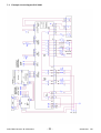
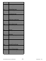
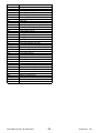
SERVICE MANUAL
COOKING
Built-in appliances and
floor-mounted stoves
with „Vision Cooking“
input electronics
© Electrolux Distriparts
Muggenhofer Straße 135
D-90429 Nürnberg
Germany
Fax +49 (0)911 323 1022
DGS-TDS-N
Edition:
05.09
Publ.-Nr.:
599 527 691
685
EN
Table of contents
1.
ESD=electrostatic discharge ................................................................................................... 3
2.
2.1
2.3
2.3.1
2.3.2
Software specifications, Functions .......................................................................................... 4
Illustration of the input electronics (UI) Vision Cooking ............................................................. 4
Main features of operation ........................................................................................................ 6
Clock setting following network reset ....................................................................................... 6
Child-proof lock ........................................................................................................................ 7
3.
3.1
3.2
3.3
3.4
Functions of appliance ............................................................................................................. 8
Oven functions, capacities and small consumer - appliance-specific .................................... 8
Pyrolitical cleaning - Explanation .............................................................................................. 9
High-speed heating (Boost) - Explanation .............................................................................. 10
Safety function safety cutoff of oven ....................................................................................... 11
4.
4.1
4.1.1
4.1.2
4.1.3
4.1.4.2
4.1.5
4.1.6
4.1.7
4.2
4.2.1
Functional parts - Component data, installation situation, dismantling ................................... 12
Functional parts - Oven control .............................................................................................. 12
Input electronic (UI) Vision Cooking ........................................................................................ 12
Power electronic OVC2000 .................................................................................................... 13
Temperatursensor PT500 ...................................................................................................... 14
Door locking system, motorics with door-switch light ............................................................ 15
Door switch for the light .......................................................................................................... 16
Luminous bar in the control panel .......................................................................................... 17
Odour filter (catalytic converter electrically) ........................................................................... 18
Functional parts - Cooking setting control .............................................................................. 20
Power controller ..................................................................................................................... 20
5.
5.1
5.2
5.4
Technical equipment .............................................................................................................. 22
Temperature safety device ..................................................................................................... 22
Fan after-running .................................................................................................................... 22
Oven rack protective circuit .................................................................................................... 23
6.
6.1
6.2
6.3
6.3.1
6.3.2
6.4
Fault diagnosis/ What to do if ...? ........................................................................................... 24
Alarmmanagement (Faultcodes) ............................................................................................ 24
Measuring the temperature sensor ........................................................................................ 25
Demo Mode Input electronic Vision Cooking .......................................................................... 26
Activating / deactivating Version a .......................................................................................... 26
Activating / deactivating Version b .......................................................................................... 27
Factory test for appliances with meat thermometer pin ......................................................... 28
7.
7.1
7.3
7.7
Wiring diagram / measuring points ........................................................................................ 31
Connection Point Overview .................................................................................................... 31
Example circuit diagram OVC 2000 ....................................................................................... 32
Operative Equipment Overview .............................................................................................. 33
Changes ............................................................................................................................................... 36
DGS-TDS-N 05.09 A. B. © Electrolux
-2-
599 527 691
EN
1.
ESD=electrostatic discharge
As the single electronic interfaces are not protected internally against statical electricity and are
partially open, you must pay attention to that, in case of a repair, there will be a potential
compensation via the housing of the appliance (touch it) in order to neutralize a possible charging
and to prevent a damaging of the affected electronic interface.
You also have to be careful with those electronics delivered as spare parts, which have to be put
out of the ESD protective package only after a potential compensation (discharge of possible
statical electricity).
If a potential compensation with an existing static electricity is not executed, it does not mean that
the electronic is demaged directly. Consequential damages may result due to the damaging of
internal structures which arise only in case of load through temperature and current.
Endangered are all assembly groups which are provided with control entries, wire paths lying open
and free-accessible processors.
DGS-TDS-N 05.09 A. B. © Electrolux
-3-
599 527 691
EN
2.
Software specifications, Functions
2.1
Illustration of the input electronics (UI) Vision Cooking
Displays
symbol menu point
(incl. levels of use)
time of day heating indication
Time functions
Symbol
Temperature
Weight
Functions
Display
(examples)
Timer
time of day
duration
Timer is active.
Indicates the set time of day.
Indicates the required time for the boiling process.
End
Indicates the time when the boiling process will be
finished.
Start
Temperature
Weight
Fleischsonde
Odour filter
DGS-TDS-N 05.09 A. B. © Electrolux
End with plugged-in meat probe is being calculated.
Indicates the time since when the boiling process has
been running.
Indicates the extent of oven heating.
Fast heating is active (reduced heating time).
Possibilities:
-Weight automatic system is active.
-Weight can be modified.
Possibilities:
-Meat probe is inserted.
-Meat probe automatic system is active.
-Core temperature can be modified.
Heat + Hold is active.
The odour filter has been activated.
-4-
599 527 691
EN
Touch control sensor fields
On/Off
Set values
Scroll
Main menu
Sensor field
Function
to the top/to the bottom
above in the menu
Display main menu
Confirm
Switch on or off appliance
Time functions, Select additional
functions and meat probe.
Set values (e.g. temperature,
time, weight, boiling level)
DGS-TDS-N 05.09 A. B. © Electrolux
Selection
Options
Confirm
Remark
With an active function:
- Press 1 x: Change to superior menu (function
remains active), after 5 seconds again.
Change into active menu point.
- Press 2 x: In the superior menu downward and
upward (function is deactivating).
Set functions are deactivating (besides timer).
*Activate value:
-press 1 x: symbol standing in front is flashing.
-2press 2 x: value can be set.
*Activate value:
-press 1 x: set value in single steps.
-Keep key pressed: set value in fast steps.
*When setting a period and time respectively you can
reset the display to cero by pressing + and simultaneously.
-5-
599 527 691
EN
2.3 Main features of operation
2.3.1 Clock setting following network reset
Information: The oven only functions with set time!
When connecting the appliance again, e.g. after a repair, you need not set the time anew, as the
electronic remember the time even for a longer period of time because of its technology
(condenser).
If a new input electronic is installed, or if the appliance is disconnected from power supply for a
longer time, you have to proceed as follows for setting the time:
Set language
1.
2.
3.
After electric connection the display indicates the following:
the company logo
the software version and working time
the display "set language"
Select the desired language by "-" and "+" respectively
Confirm the selected language by "OK".
Immediately you can see the texts in the set language in the display .
Set contrast and brightness
After setting the language you can see the displays "set contrast" and "set brightness". Contrast
and brightness are set according to the language (see section "Set language").
Set clock
After setting contrast and brightness, the display indicates "set time of day".
1.
2.
3.
4.
Set the hour of the current time by "-" and "+" respectively.
Confirm by "OK".
Set the current time by "-" and "+" respectively.
Confirm by "OK".
DGS-TDS-N 05.09 A. B. © Electrolux
-6-
599 527 691
EN
2.3.2 Child-proof lock
The key block does not protect against unintentional switching off. After switching off the appliance
the key block is canceled again.
When the child-proof lock has been activated, the appliance can not be put into operation.
Activate child-proof lock
No function may be selected.
1.
Touch "selection options" and "-" simultaneously until you can see a message. Child safety
function is active.
Child safety function switch off
1.
Touch "selection options" and "-" simultaneously until you can see a message. Deactivate the
child lock. Now the child lock is deactivated and the oven is in operation again.
DGS-TDS-N 05.09 A. B. © Electrolux
-7-
599 527 691
EN
3.
Functions of appliance
3.1
Oven functions, capacities and small consumer - appliance-specific
pos.
0
1
2
3
4
5
6
7
8
A
pos.
0
1
2
3
4
5
6
7
8
9
10
11
A
B
oven function
off
ring+fan
top+bottom
ring+bottom+fan
grill+top+fan (alter)
grill
grill+top
bottom
ring+fan (LTC)
def. temp.
Boost
MP
180
200
200
180
300
300
150
120/80
A
A
A
-
x
x
x
x
x
x
x
x
heating elements (Watt)
top
bottom
rear
grill element element
element
element
ResH. KeepW.
1900
1000
1000
2400
x
x
x
x
x
-
x
x
x
x
x
x
x
-
Boost (AUTO)
ring+fan
oven function
off
ring+fan
top+bottom
ring+bottom+fan
grill+top+fan (alter)
grill+top+fan+tsp (alter)
grill
grill+tsp
grill+top
grill+top+tsp
bottom
ring+fan (LTC)
def. temp.
Boost
MP
180
200
200
180
180
300
300
300
300
150
120/80
A
A
A
B
-
x
x
x
x
x
x
x
x
x
x
x
Boost (AUTO)
ring+fan
ring+fan+tsp
X
X
X
-
X
X
X
-
X
X
X
X
X
X
X
X
X
X
X
X
X
X
X
X
X
X
X
X
X
X
X
X
X
X
X
X
X
X
X
2530
2090
3530
3030
1990
2990
1090
2530
11,0
9,1
15,3
13,2
8,7
13,0
4,7
11,0
-
-
-
X
X
X
X
X
2530
11,0
heating elements (Watt)
top
bottom
rear
element
element
element
1000
1000
2400
x
x
x
x
x
x
x
x
x
x
-
small loads (Watt)
oven lamp oven lamp max power
(W)
current (A)
cooling fan back wall side wall
25
40
25
X
X
X
-
grill element
ResH. KeepW.
1900
x
x
x
x
x
x
-
cooking
fan
40
cooking
fan
40
small loads (Watt)
oven lamp lamp side
cooling fan back wall
wall
25
40
25
turnspit
5
max power
(W)
current (A)
X
X
X
X
X
X
-
X
X
X
X
X
-
X
X
X
-
X
X
X
X
X
X
X
X
X
X
X
X
X
X
X
X
X
X
X
X
X
X
X
X
X
X
X
X
X
X
X
X
X
X
X
X
X
X
X
X
X
X
X
X
-
2530
2090
3530
3030
3035
1990
1995
2990
2995
1090
2530
11,0
9,1
15,3
13,2
13,2
8,7
8,7
13,0
13,0
4,7
11,0
-
-
-
X
X
X
X
X
X
X
X
X
X
X
2530
2535
11,0
11,0
heating element (Watt)
small loads (Watt)
pos.
oven function
def. temp.
Boost
grill element
top element
bottom element
rear element
cooking fan
cooling fan
oven lamp back wall
oven lamp side wall
turnspit
max. power (W)
current (A)
off
ring + fan
top + bottom
ring + bottom + fan
grill + top + fan (alter)
grill + top + fan + tsp (alter)
grill
grill + tsp
grill + top
grill + top + tsp
bottom
ring + fan (LTC)
Boost (auto)
ring + fan
ring + fan + tsp
DGS-TDS-N 05.09 A. B. © Electrolux
-8-
599 527 691
EN
3.2
Pyrolitical cleaning - Explanation
°C
end of heating phase
500
400
cooling phase
door locked
300
200
door unlocked
100
room temperature
120 P3 150 P2
90
min
P1
Fig. heating-up curve temperature (°C) / time (min
With the Pyroluxe self-cleaning system the residues in the interior are carbonized to ashes at high
temperatures. The centre of gravity temperature of the muffle is approx. 500°C.
A max. selection of three pyrolysis durations (P…) can be made per appliance class and
equipment.
Pyrolysis duration (Heating period)
P1 (Heavy)
P2 (Normal)
P3 (Light)
Note:
>
>
>
Heating period
Heating period
Heating period
150min
120min
90min
In appliances which are equipped with two pyrolysis durations, P2 corresponds to the
pyrolysis duration P3.
DGS-TDS-N 05.09 A. B. © Electrolux
-9-
599 527 691
EN
The oven door is locked at a centre of gravity temperature of the muffle of approx. 312°C, after a
heating-up time of approx. 11 min.
The oven door is unlocked at a centre of gravity temperature of the muffle of approx. 204°C. The
moment depends on the selected pyrolytic duration.
The cooling fan is running at an increased speed until the moment of unlocking. At a centre of
gravity temperature of the muffle of approx. 130°C it switches off.
Attention écart pour les appareils stationnaires
3.3
High-speed heating (Boost) - Explanation
Explanation:
Quick-Heating means reaching the selected oven temperature as quickly as
possible.
After reaching the oven temperature, it switches back to the originally selected
oven function (heating element configuration).
The Quick-Heating function is displayed depending on the appliance either by a
symbol or by animated bar.
Note:
Quick-Heating function - manual operation
Quick-Heating function „AUTO“ - Automatically active, not switchable
The type of Quick-Heating function (Boost) available is in Chapter 3.1.
DGS-TDS-N 05.09 A. B. © Electrolux
- 10 -
599 527 691
EN
3.4
Safety function safety cutoff of oven
If the oven is not switched off after a specific period of time or if the temperature is not changed,
then it switches off automatically.
The oven switches off at an oven temperature of:
Putting into operation after a safety cutoff:
In the display you can see the indication „automatic safety disconnection system active“. Continue
by OK.
Note:
The safety cutoff is cancelled, when the clock function „duration“ or „end“ has been set.
Furthermore, it is not active with the functions, low-temperature cooking and Pyrolyse.
DGS-TDS-N 05.09 A. B. © Electrolux
- 11 -
599 527 691
EN
4.
Functional parts - Component data, installation situation, dismantling
4.1 Functional parts - Oven control
4.1.1 Input electronic (UI) Vision Cooking
In addition to diverse semi-conductor modules, the Vision Cooking input electronics mainly includes
a LCD display and a microprocessor. This controls the electronic control unit via a personalised
program. The desired oven functions are set by a so-called touch board which is a common spare
part with the control panel.
Fig.: user interface in built-in condition
Fig. 1
Fig. 2
Fig. 3
The user interface is positioned firmly in a plastic housing (E-box). The whole unit is locked in the
panel support. When opening the appliance please pay attention to that the control board for the
luminous bar is fixed in the control panel from below to the front housing lid (figure 1). After drawing
off the lines you can disassemble the front cover lid. After pressing in the four hooking noses at the
bottom side of the plastic housing (figure 2) you can remove the user interface to the back, in
direction of the interior of the appliance (figure 3). With upright stoves, there may be different
scenarios of fitting positions.
DGS-TDS-N 05.09 A. B. © Electrolux
- 12 -
599 527 691
EN
4.1.2 Power electronic OVC2000
Connections for
Relay for
- meat thermometer
- door lock
- Temperature sensor
- door lock
- telescopic bars
- data link
- lighting
- fan, moto
Power supply
Relay for
50....60Hz
230V AC
- all-pole cutoff
Fig.: Powerboard OVC2000 wired in the appliance
Fig.: assembly situation
Fig.: Spare part OVC2000
The power electronics are located on the rear side of the appliance and are accessible after
removing the housing rear panel. The power board is installed in a so-called „functions box“ made
of plastic. These two components, power electronics and plastic box, are also a replacement part
unit (see Ill.)
Please refer to Chapter 7 for connection designations and possible measuring points.
DGS-TDS-N 05.09 A. B. © Electrolux
- 13 -
599 527 691
EN
4.1.3 Temperatursensor PT500
The temperature in the baking oven is measured by a temperature sensor (type PT 500) for
appliances with control board. The sensor is provided at the rear of the appliance. It is used to
transmit to the electronic systems the values for:
cyclic heating the radiators until the selected temperature is reached;
switch off the radiators in case of overheating of defective sensor;
switching ON/OFF the cooling fan.
Fig. Temperature sensor
Fig. Electrical resistance of sensor depending on the ambient temperature
DGS-TDS-N 05.09 A. B. © Electrolux
- 14 -
599 527 691
EN
4.1.4.2
Door locking system, motorics with door-switch light
Fig.: Door locking system as complete component
Drive motor
Double micro switch
Above:
Lock
Below:
Oven lighting switch
Curve pane
Sliding micro switch - Lighting
Sliding door locking system
DGS-TDS-N 05.09 A. B. © Electrolux
- 15 -
599 527 691
EN
4.1.5 Door switch for the light
Switch axis
Electrical terminals
When opening the door of the oven, the lighting of the oven is activated over this component after
the device has been switched on. The mounting position is at the top and right-hand corner of the
front frame of the oven
DGS-TDS-N 05.09 A. B. © Electrolux
- 16 -
599 527 691
EN
4.1.6 Luminous bar in the control panel
Figures show the luminous bar as a separate component and the electric terminals from the sight
of the interior of the appliance, each at the left and at the right. The assembly situation is in the
switch panel support. For disassembling the luminous bar you have to remove the switch panel.
The luminous bar is selected by a selection electronic system which is mounted at the bottom side
to the front cover of the appliance. It supplies the luminous bar with the supply voltage of 7 V / 18
mA.
DGS-TDS-N 05.09 A. B. © Electrolux
- 17 -
599 527 691
EN
4.1.7 Odour filter (catalytic converter electrically)
Fig. 1
Fig. 2
Fig. 3
In order to disassemble the odour filter in case of a defect, you must proceed as follows:
-
Disassemble the appliance, open the housing lid
Disassembly of the air channel upper part (figure 1 + 2).
Loosen the six connecting screws air channel lower part / adapter odour filter (figure 3)
DGS-TDS-N 05.09 A. B. © Electrolux
- 18 -
599 527 691
EN
Fig. 4
-
Fig. 5
Fig. 6
Remove the air channel lower part (figure 4).
Loosen the four connecting screws adapter odour filter / odour filter (figure 5).
Remove the adapter odour filter (figure 6).
Fig. 7
Fig. 8
Fig. 9
-
Loosen the four connecting screws odour filter / oven muffle (figure 7). It is also necessary to
cut the oven insulating in order to remove the odour filter (figures 8 + 9).
-
When assembling the odour filter please proceed in the reversed
order and pay attention to the careful combination of the oven
insulating.
DGS-TDS-N 05.09 A. B. © Electrolux
- 19 -
599 527 691
EN
4.2 Functional parts - Cooking setting control
4.2.1 Power controller
Fig. Power controller
Fig. Switch in „OFF“ position
Input voltage 230 V
Fig. Performance characteristic
K1 – Knob position
% ED – Switching on period in percent
100 % corresponds to a switching on period of 41 seconds
The hot plates are controlled via the bimetallic contact P 1-2. The input voltage of 230 V is applied
here.
Depending on the position of the knob, this contact determines how often the hot plate is switched
on or off during a certain unit of time by cycling the maximum heating power (230 V or 0 V between
contact 2 and 4) (refer to performance characteristic).
Continuous operation at max. heating power is hot plate 9.
The power characteristic shows the power controller in cycling mode.
The average switching on period for each knob position can be read off in % of the cycled and/or
max. power.
DGS-TDS-N 05.09 A. B. © Electrolux
- 20 -
599 527 691
EN
Dual circuit heating
element
Dual circuit regulator
DGS-TDS-N 05.09 A. B. © Electrolux
- 21 -
599 527 691
EN
5.
Technical equipment
5.1
Temperature safety device
With built-in appliances, there is a temperature fuse on the side of the air channel that switches off
the appliance in the event of overheating. The measured temperature value during a cutoff is 90°C.
Fig.: Built-in position - Temperature fuse
Notes:
5.2
-
for wiring diagram see chapter 7
Deviations possible with floor-mounted stoves
Fan after-running
The cooling fan switches on automatically when putting the appliance into operation. First it is in
operation to keep cool the appliance surfaces. After the oven was switched off, the fan continues
running to cool the appliance and then switches off automatically at a centre of gravity temperature
of the muffle of approx. 120°C-130°C. The post-operative ventilation is controlled via the
electronics.
Note:
-
for wiring diagram see chapter 7
Deviations possible with floor-mounted stoves
DGS-TDS-N 05.09 A. B. © Electrolux
- 22 -
599 527 691
EN
5.4
Oven rack protective circuit
Appliances with Pyroluxe self-cleaning system are provided with a microswitch. Dieser Mikroschalter befindet sich an der linken äußeren Seite der Komponentenplatte. Only with attached oven
racks, not with slide-in grids, the microswitch interrupts a switch contact which prevents an
activating of the pyrolytic function.
Note:
for wiring diagram see chapter 7
DGS-TDS-N 05.09 A. B. © Electrolux
- 23 -
599 527 691
EN
6.
Fault diagnosis/ What to do if ...?
6.1
Alarmmanagement (Faultcodes)
Alarmmanagement Powerboards Prisma, OVC1000 und OVC2000
Display
F0
F1
F2
F3
F94
F4
F5
F95
F96
F6
F7
F8
F9
F10
F11
F91
F12
F13
F14
F15
F16
Description of fault
Fault repair
replace power electronics
door cannot be locked
Test door locking system
door cannot be unlocked
Test door locking system and unlocking thermostat
f11
software error
Execute network reset by disconnecting the
appliance from the electricity supply and restarting
Temperature sensor alarm - resulting in F4
Test temperature sensor, replace if necessary
Temperature sensor without contact or short circuit Test temperature sensor, replace if necessary
Clotted heating element relay contacts on the
power electronics
Replace power electronics
Temperature alarm at power electronics - resulting Test built-in situation of the ventilation channel and
in F6
the function of the cooling fan
Temperature alarm at power electronics - resulting Test built-in situation of the ventilation channel and
in F6
the function of the cooling fan
Power electronics temperature too high
Test built-in situation of the ventilation channel and
the function of the cooling fan
Faulty electrical connection (only in appliances
Correctly connect the appliance and re-start
with Prisma power electronics)
No connection between power electronics and
Check connection line - replace electronic systems if
input electronics
necessary
Micro processor resets itself independently (=
Execute network reset by disconnecting the
Reset)
appliance from the electricity supply and restarting
Triac on power electronics defect
Activate Main Button, select an operation modus
with hot air, wait for cooling ventilation start, replace
power electronics again in the event of an error report
following approximately 20 seconds
Meat skewer sensor without contact or shortCheck meat thermometer, also check bushing and
circuited
wiring if necessary; if all this OK replace power
electronics
Temperature sensor alarm for steam generator Test temperature sensor, replace if necessary
resulting in F12
Temperature sensor of steam generator without
Test temperature sensor, replace if necessary
contact or short-circuited
Internal electronics error
Replace power electronics
software error
Replace input electronics
Internal electronics error
Replace input electronics
Combined alarm Pyrolytic cleaning/cooking zone Replace input electronics
Internal error
DGS-TDS-N 05.09 A. B. © Electrolux
- 24 -
599 527 691
EN
6.2
Measuring the temperature sensor
If a failure at the temperature sensor is assumed, the resistance can be checked by means of an
ohmmeter.
The resistance of the temperature sensor should be 500 – 600 ohms at room temperature.
Make sure to measure the insulation resistance between the metallic housing and each connection
terminal.
The resistance should be higher than 2 MOhms.
Abb. Measuring the temperature sensor
DGS-TDS-N 05.09 A. B. © Electrolux
- 25 -
599 527 691
EN
6.3
Demo Mode Input electronic Vision Cooking
Both demo mode versions possible.
6.3.1 Activating / deactivating Version a
The following steps (1-3) should be done within 10
sec.
1.
Oven in OFF state
2.
Keep pressed Mainswitch for 5 seconds
until oven switches OFF again.
A signal is audible
3.
Keep pressed “Timer-” and “Minus-” key
simultaneously for 1 second.
Sound: beep, beep, beep…confirms
4.
Once oven is switched ON “DEMO” is displayed.
Deactivation vice versa
After 10 sec. or once another key has been pushed Demo Mode can’t be activated anymore,
but procedure can be started from the beginning.
DGS-TDS-N 05.09 A. B. © Electrolux
- 26 -
599 527 691
EN
6.3.2 Activating / deactivating Version b
Fig. 1
Start position:
The appliance must be switched off.
Display:
"Time" (fig. 1).
Operating step 1:Press the main switch for 5 seconds (fig. 1), the appliance switches itself "ON"
and then "OFF" again.
Display:
"Standby" (fig. 2) ---> "Time" (fig. 3).
Acoustic signal:
1x "Beep" as confirmation.
Fig. 2
Fig. 3
Operating step 2:
Simultaneous pressing of the two buttons "Timer" and "Minus" for 2
seconds (fig. 4).
Acoustic signal:
3 x "Beep" as confirmation.
Fig. 4
Operating step 3:
Switching the appliance on with the main switch
Display:
active Demo Mode
deactivated Demo Mode
Fig. 5
DGS-TDS-N 05.09 A. B. © Electrolux
---> "DEMO" (fig. 5).
---> none (fig. 6)
Fig. 6
- 27 -
599 527 691
EN
6.4
Factory test for appliances with meat thermometer pin
The factory test can only be activated during the display of the brand logo, after the appliance has
been connected anew!
Actuate the touch pads simultaneously until you can hear a signal (beep). The factory test starts
with the
---> consumer test
Depending on the appliance group (see tables) you can switch through various consumers in five
steps and check them for function by using the touch pad. This cycle can be repeated as often as
desired.
x
x
x
x
x
x
x
x
x
x
x
x
x
x
x
x
x
DGS-TDS-N 05.09 A. B. © Electrolux
x
x
x
x
x
- 28 -
Wrasenventil
Oven lamp
x
Cooling fan
x
electric odour filter
x
Turnspit motor
1
2*
3
4
5
Hot air motor
x
Steam generator.
with Pyrolyse
1
2*
3
4
5
Annular heating element
x
Steam
1
2*
3
4
5
Upper heat
Step
x
Lower heat
appliance group
without Pyrolys
1
2*
3
4
5
with Pyrolyse
and spit
Grill heater element
symbol is indicated in the display
slowly
slowly
slowly
slowly
slowly
x
slowly
fast
slowly
slowly
slowly
x
x
x
x
x
x
x
x
slowly
fast
slowly
slowly
fast
x
slowly
fast
slowly
slowly
fast
x
x
x
x
x
x
x
599 527 691
EN
Continue by using the touch pad
---> temperature sensor test
The current oven temperature is measured and indicated in the display.
---> meat thermometer test
Insert the meat spit into the respective plug socket,
the currently measured temperature of the meat thermometer is indicated.
Continue by using the touch pad
---> information on the input electronic version
Following information is indicated one after the other:
-
firmware version of input electronic
configuration version of input electronic
working time of oven
Example
EBAIB205
V02IB012
0
Continue by using the touch pad
---> display Test
-
complete indication of display
display completely dark
complete display in checker pattern
indication of single pixels
Continue by using the touch pad
---> display brightness
By the touch pads "+" and "-" you can set the brightness of the display.
DGS-TDS-N 05.09 A. B. © Electrolux
- 29 -
599 527 691
EN
Continue by using the touch pad
---> door locking test
-
is automatically started with appliances with pyrolisis.
In order to operate the appliance normal again and to leave the factory test respectively you must
disconnect it from the mains and connect it again!
DGS-TDS-N 05.09 A. B. © Electrolux
- 30 -
599 527 691
EN
7.
Wiring diagram / measuring points
7.1
Connection Point Overview
DGS-TDS-N 05.09 A. B. © Electrolux
- 31 -
599 527 691
EN
7.3
Example circuit diagram OVC 2000
DGS-TDS-N 05.09 A. B. © Electrolux
- 32 -
599 527 691
EN
7.7
Operative Equipment Overview
Kennzeichen
a1
a2
a3
a4
a7
a7.1
a8
a15
a31
a32
a33
a34
a61
a62
a73
a84
A1
A2
b3
BOF
BOT
c4
D
DS
e1
e11
E
F
f1
f1.1
f2
f2.1
f5
f6
f7
f8
f11
f12
f15
f16
f19
f21
f22
f31
f32
f33
f34
G5
h1
h1.1
h1.4
h1.5
h1.6
h1.7
EN
Description
Switch 7-step front left
Switch 7-step rear left
Switch 7-step rear right
switch 7-step front right
Heating mode selector main oven
Heating mode selector top oven
LTC(Low Temp. Cooking) switch
Touch electronic switch warming zone
energy regulator front left
energy regulator rear left
energy regulator rear right
energy regulator front right
touch electronic switch front left
touch electronic switch rear left
touch electronic switch rear right
touch electronic switch front right
actuator exhaust
Actuator desteam
Socket meatprobe
mode selector function
mode selector temperature
interference filter
hob connector 12-pol.
door switch
Door look pyro
Distributor plate pot detection
hob connector 8-pol.
hob connector 21pol
Main oven thermostat
Top oven thermostat
safety temp. limiter main oven
safety temp. limiter top oven
Thermostat cooling fan delay
Thermostat fast run cooling fan pyro
sensor to magnetron
LTC(Low Temp. Cooking) termostat
Thermostat unlock pyro
Thermostat cooling fan delay
2. safety temp. limiter oven
thermostat overheating warning
rack thermostat
saftey temp. limiter grill
saftey temp. limiter fryer
residual contact front left
residual contact rear left
residual contact rear right
residual contact front right
magnetron
Lamp working
lamp working top oven
lamp working hot plate front left
lamp working hot plate rear left
lamp working hot plate rear right
lamp working hot plate front right
DGS-TDS-N 05.09 A. B. © Electrolux
- 33 -
599 527 691
EN
Kennzeichen
h3
h3.1
h4
h4.1
h4.6
h5
h5.1
h7
h9
h10
h11
h12
h20
h30
h40
h52
K
k1
KS
KS1
KS2
KS3
KS4
M1
M2
M3
M4
M5
m1
m2
m3
m4
m5
m6
m8
m12
m13
m20
N1
N2
N3
N4
N5
PE3
PE4
PE/1b
Q1
r6
r7
r7.1
r8
r8.1
r11
r12
EN
Description
lamp heating main oven
lamp heating top oven
oven lamp main oven
oven lamp side main oven
lamp halogen
oven lamp top oven
oven lamp side top oven
meatprobe display
lamp overheating
analog timer
electronic timer
6-push electronic timer
timer primary code hob
residual lamp
display board
display oven
clutch
LTC(Low Temp. Cooking) relay
switch child safety
rotary hot plate front left
rotary hot plate rear left
rotary hot plate rear right
rotary hot plate front right
Hob connector 14-pol. 1+2
Hob connector 14-pol. 3+4
Connector 11-pol.
Connector 7-pol.
Connector 3-pol.
fan hot air
fan cooling
transformer halogen lamp
transformer timer
transformer electronic
motor stirrer
transformer high voltage
turnspit motor
Ignition coil gas
cooling fan, L3
electronic powerboard
modul of induction
electronic board Rhea
connector board
Power supply unit lightbar
ground point front frame left
ground point front frame right
ground point component plate
quick start module top oven
top heating/grill combination
main oven top heating element
top oven top heating element
main oven bottom heating element
top oven bottom heating element
fat and smell
thermal switch
DGS-TDS-N 05.09 A. B. © Electrolux
- 34 -
599 527 691
EN
Kennzeichen
r14
r14.1
r15
r16
r19
r20
r21
r22
r27
r27.1
r31
r32
r33
r34
r35
s1
s2
s3
s4
s11
s12
s13
s14
s19
s21
s22
s23
s31
s32
s33
s34
TR
X1
X10
X11
X12
x20
EN
Description
main oven grill heating element
top oven grill heating element
warming zone
rear
rack heating
preresistor cooling fan
heater grill
heater fryer
preresistor oven lamp
preresistor oven lamp side
cooking plate front left
cooking plate rear left
cooking plate rear right
cooking plate front right
cooking plate middle
sensor pot detection front left
sensor pot detection rear left
sensor pot detection rear right
sensor pot detection front right
micro switch gas to electro
micro switch grill to fryer
micro switch grill socket
micro switch sensor
rack switch
sensor grill
sensor fryer
Sensor wok (middle)
Ignition switch front left
Ignition switch rear left
Ignition switch rear right
Ignition switch front right
telescopic runner switch
main terminal
tandem pin shells 6-pol.
tandem pin shells 8-pol.
connector hob
frame connector, L3
DGS-TDS-N 05.09 A. B. © Electrolux
- 35 -
599 527 691
EN
Changes
Pages
24,
Chapter 6.1
DGS-TDS-N 05.09 A. B. © Electrolux
changed
- 36 -
599 527 691
EN