1
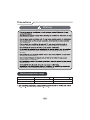
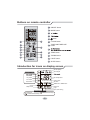
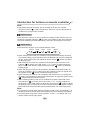
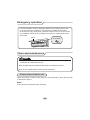
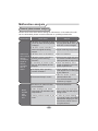
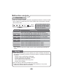
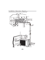
BK 5200 BK 6300 Split Air Conditioner User Manual Content Operation Notices Precautions............................................................................................................1 Parts name ............................................................................................................2 Screen Operation Guide Buttons on remote controller .................................................................................3 Introduction for icons on display screen ................................................................3 Introduction for buttons on remote controller.........................................................4 Function introduction for combination buttons.......................................................8 Operation guide .....................................................................................................9 Replacement of batteries in remote controller.......................................................9 Emergency operation ..........................................................................................10 Maintenance Clean and maintenance.......................................................................................10 Malfunction Malfunction analysis ............................................................................................13 Installation Notice Installation dimension diagram ............................................................................17 Tools for installation .............................................................................................18 Selection of installation location ..........................................................................18 Requirements for electric connection ..................................................................19 Installation Installation of indoor unit......................................................................................20 Installation of outdoor unit ...................................................................................25 Vacuum pumping.................................................................................................28 Leakage detection ...............................................................................................28 Check after installation ........................................................................................29 Test and operation Test operation ......................................................................................................29 Attachment &RQ¿JXUDWLRQRIFRQQHFWLRQSLSH .........................................................................30 Pipe expanding method.......................................................................................32 This appliance is not intended for use by persons (including children) with reduced physical, sensory or mental capabilities or lack of experience and knowledge, unless they have been given supervision or instruction concerning use of the appliance by a person responsible for their safety. Children should be supervised to ensure they are away from the appliance. Do not dispose this product as unsorted municipal waste. Collection of such waste separately for special treatment is necessary. Precautions Warning cause electric shock. may be broken. damage. Please contact dealer when you need to repair air conditioner. person can perform the work. Otherwise, it may cause personal injury or damage. damage or personal injury. personal injury or damage. electric shock. Otherwise, it may cause personal injury or damage. Working temperature range Maximum cooling Minimum heating 18 ~43 Indoor side DB/WB( 32/23 20/- ; for heat pump unit is -7 ~ 43 1 ) . Outdoor side DB/WB( 43/-7/- ) Parts name Indoor Unit air inlet panel ¿OWHU aux.button KRUL]RQWDOORXYHU cooling indicator power indicator air outlet receiver window display heating indicator temp. indicator drying indicator (Display content or position may be different from above graphics, please refer to actual products) remote control Outdoor Unit air inlet Connection wire air outlet Notice: $FWXDOSURGXFWPD\EHGLIIHUHQWIURPDERYHJUDSKLFVSOHDVHUHIHUWRDFWXDO products. 2 Buttons on remote controller 1 ON/OFF button 2 MODE button 3 4 5 2 1 3 4 button 6 CLOCK button 7 TIMER ON/TIMER OFF button 5 8 6 8 7 10 9 12 11 9 TEMP button 10 TURBO button 11 LIGHT button 12 SLEEP button Introduction for icons on display screen Set fan speed Send signal Operation mode Cool mode Dry mode Set temperature Fan mode Turbo mode Set time Heat mode TIMER ON / TIMER OFF Clock Child lock Light Up & down swing Sleep mode Temp. display type :Set temp. :Indoor ambient temp. :Outdoor ambient temp. 3 Introduction for buttons on remote controller Note: Ɣ$IWHUSXWWLQJWKURXJKWKHSRZHUWKHDLUFRQGLWLRQHUZLOOJLYHRXWDVRXQG 2SHUDWLRQLQGLFWRULV21UHGLQGLFDWRU$IWHUWKDW\RXFDQRSHUDWHWKHDLU conditioner by using remote controller. 1 ON/OFF button 3UHVVWKLVEXWWRQFDQWXUQRQRUWXUQRIIWKHDLUFRQGLWLRQHU$IWHUWXUQLQJRQWKHDLU FRQGLWLRQHURSHUDWLRQLQGLFDWRURQLQGRRUXQLW¶VGLVSOD\LV21JUHHQLQGLFDWRU The colour is different for different models), and indoor unit will give out a sound. 2 MODE button Press this button to select your required operation mode. $872 COOL DRY )$1 +($7 Ɣ:KHQVHOHFWLQJDXWRPRGHDLUFRQGLWLRQHUZLOORSHUDWHDXWRPDWLFDOO\DFFRUGLQJ WRH[IDFWRU\VHWWLQJ6HWWHPSHUDWXUHFDQ¶WEHDGMXVWHGDQGZLOOQRWEHGLVSOD\HG DVZHOO3UHVV)$1EXWWRQFDQDGMXVWIDQVSHHG3UHVVEXWWRQFDQDGMXVW fan blowing angle. Ɣ$IWHUVHOHFWLQJFRROPRGHDLUFRQGLWLRQHUZLOORSHUDWHXQGHUFRROPRGH&RRO LQGLFDWRURQLQGRRUXQLWLV213UHVVRUEXWWRQWRDGMXVWVHWWHPSH UDWXUH3UHVV)$1EXWWRQWRDGMXVWIDQVSHHG3UHVVEXWWRQWRDGMXVWIDQ blowing angle. Ɣ:KHQVHOHFWLQJGU\PRGHWKHDLUFRQGLWLRQHURSHUDWHVDWORZVSHHGXQGHUGU\ PRGH'U\LQGLFDWRURQLQGRRUXQLWLV218QGHUGU\PRGHIDQVSHHGFDQ¶W be adjusted. Press " " button to adjust fan blowing angle. Ɣ:KHQVHOHFWLQJIDQPRGHWKHDLUFRQGLWLRQHUZLOORQO\EORZIDQQRFRROLQJDQG QRKHDWLQJ$OOLQGLFDWRUVDUH2))3UHVV)$1EXWWRQWRDGMXVWIDQVSHHG3UHVV " " button to adjust fan blowing angle. Ɣ:KHQVHOHFWLQJKHDWLQJPRGHWKHDLUFRQGLWLRQHURSHUDWHVXQGHUKHDWPRGH +HDWLQGLFDWRURQLQGRRUXQLWLV213UHVVRUEXWWRQWRDGMXVWVHW WHPSHUDWXUH3UHVV)$1EXWWRQWRDGMXVWIDQVSHHG3UHVVEXWWRQWRDGMXVW IDQEORZLQJDQJOH&RROLQJRQO\XQLWZRQ¶WUHFHLYHKHDWLQJPRGHVLJQDO,IVHWWLQJ KHDWPRGHZLWKUHPRWHFRQWUROOHUSUHVV212))EXWWRQFDQ¶WVWDUWXSWKHXQLW Note: Ɣ)RUSUHYHQWLQJFROGDLUDIWHUVWDUWLQJXSKHDWLQJPRGHLQGRRUXQLWZLOOGHOD\a minutes to blow air (actual delay time is depend on indoor ambient temperature). Ɣ6HWWHPSHUDWXUHUDQJHIURPUHPRWHFRQWUROOHUać ; Fan speed: auto, low speed, medium speed, high speed. 4 Introduction for buttons on remote controller 3 EXWWRQ Ɣ3UHVVRUEXWWRQRQFHLQFUHDVHRUGHFUHDVHVHWWHPSHUDWXUHć . +ROGLQJRUEXWWRQVODWHUVHWWHPSHUDWXUHRQUHPRWHFRQWUROOHUZLOO FKDQJHTXLFNO\2QUHOHDVLQJEXWWRQDIWHUVHWWLQJLV¿QLVKHGWHPSHUDWXUHLQGLFD WRURQLQGRRUXQLWZLOOFKDQJHDFFRUGLQJO\7HPSHUDWXUHFDQ¶WEHDGMXVWHGXQGHU auto mode) Ɣ:KHQVHWWLQJ7,0(5217,0(52))RU&/2&.SUHVVRUEXWWRQWR adjust time. (Refer to CLOCK, TIMER ON, TIMER OFF buttons) When setting 7,0(5217,0(52))RU&/2&.SUHVVRUEXWWRQWRDGMXVWWLPH5HIHU to CLOCK, TIMER ON, TIMER OFF buttons) 4 )$1EXWWRQ 3UHVVLQJWKLVEXWWRQFDQVHWIDQVSHHGFLUFXODUO\DVDXWR$872ORZPHGLXP ( ), high( ). Auto Note: Ɣ8QGHU$872VSHHGDLUFRQGLWLRQHUZLOOVHOHFWSURSHUIDQVSHHGDXWRPDWLFDOO\ DFFRUGLQJWRH[IDFWRU\VHWWLQJ Ɣ)DQVSHHGXQGHUGU\PRGHLVORZVSHHG 5 button Press this button can select up&down swing angle. Fan blow angle can be selected circularly as below: no display KRUL]RQWDOORXYHUVVWRSV at current position) Ɣ:KHQVHOHFWLQJDLUFRQGLWLRQHULVEORZLQJIDQDXWRPDWLFDOO\+RUL]RQWDO louver will automatically swing up & down at maximum angle. Ɣ:KHQVHOHFWLQJǃ ǃ ǃ ǃDLUFRQGLWLRQHULVEORZLQJIDQDW¿[HG SRVLWLRQ+RUL]RQWDOORXYHUZLOOVWRSDWWKH¿[HGSRVLWLRQ Ɣ:KHQVHOHFWLQJǃ ǃDLUFRQGLWLRQHULVEORZLQJIDQDW¿[HGDQJOH +RUL]RQWDOORXYHUZLOOVHQGDLUDWWKH¿[HGDQJOH Ɣ+ROGEXWWRQDERYHVWRVHW\RXUUHTXLUHGVZLQJDQJOH:KHQUHDFKLQJ\RXU required angle, release the button. Note: Ɣǃ ǃ " may not be available. When air conditioner receives this signal, the air conditioner will blow fan automatically. 5 Introduction for buttons on remote controller 6 CLOCK button Press this button to set clock time. " " icon on remote controller will blink. Press RUEXWWRQZLWKLQVWRVHWFORFNWLPH(DFKSUHVVLQJRIRUEXWWRQFORFN WLPHZLOOLQFUHDVHRUGHFUHDVHPLQXWH,IKROGRUEXWWRQVODWHUWLPHZLOO change quickly. Release this button when reaching your required time. Press &/2&.EXWWRQWRFRQ¿UPWKHWLPHLFRQVWRSVEOLQNLQJ Note: Ɣ&ORFNWLPHDGRSWVKRXUPRGH Ɣ7KHLQWHUYDOEHWZHHQWZRRSHUDWLRQFDQ¶WH[FHHGVV2WKHUZLVHUHPRWHFRQWUR ller will quit setting status. Operation for TIMER ON/TIMER OFF is the same. 7 TIMER ON / TIMER OFF button Ɣ7,0(521EXWWRQ 7,0(521EXWWRQFDQVHWWKHWLPHIRUWLPHURQ$IWHUSUHVVLQJWKLVEXWWRQ LFRQGLVDSSHDUVDQGWKHZRUG21RQUHPRWHFRQWUROOHUEOLQNV3UHVVRU EXWWRQWRDGMXVW7,0(521VHWWLQJ$IWHUHDFKSUHVVLQJRUEXWWRQ7,0(5 21VHWWLQJZLOOLQFUHDVHRUGHFUHDVHPLQ+ROGRUEXWWRQVODWHUWKH time will change quickly until reaching your required time. 3UHVV7,0(521WRFRQ¿UPLW7KHZRUG21ZLOOVWRSEOLQNLQJLFRQ resumes displaying. Cancel TIMER ON: Under the condition that TIMER ON is started up, press "TIMER ON" button to cancel it. Ɣ7,0(52))EXWWRQ 7,0(52))EXWWRQFDQVHWWKHWLPHIRUWLPHURII$IWHUSUHVVLQJWKLVEXWWRQ LFRQGLVDSSHDUVDQGWKHZRUG2))RQUHPRWHFRQWUROOHUEOLQNV3UHVVRU EXWWRQWRDGMXVW7,0(52))VHWWLQJ$IWHUHDFKSUHVVLQJRUEXWWRQ7,0(5 2))VHWWLQJZLOOLQFUHDVHRUGHFUHDVHPLQ+ROGRUEXWWRQVODWHUWKH time will change quickly until reaching your required time. Press "TIMER OFF" word "OFF" will stop blinking. " " icon resumes displaying. Cancel TIMER OFF. Under the condition that TIMER OFF is started up, press "TIMER OFF" button to cancel it. Note: Ɣ8QGHURQDQGRIIVWDWXV\RXFDQVHW7,0(52))RU7,0(521VLPXOWDQHRXVO\ Ɣ%HIRUHVHWWLQJ7,0(521RU7,0(52))SOHDVHDGMXVWWKHFORFNWLPH Ɣ$IWHUVWDUWLQJXS7,0(521RU7,0(52))VHWWKHFRQVWDQWFLUFXODWLQJYDOLG $IWHUWKDWDLUFRQGLWLRQHUZLOOEHWXUQHGRQRUWXUQHGRIIDFFRUGLQJWRVHWWLQJWLPH 212))EXWWRQKDVQRHIIHFWRQVHWWLQJ,I\RXGRQ¶WQHHGWKLVIXQFWLRQSOHDVH use remote controller to cancel it. 6 Introduction for buttons on remote controller 8 ;)$1EXWWRQ 3UHVVWKLVEXWWRQXQGHUFRRODQGGU\PRGHWRVWDUWXS[IDQIXQFWLRQDQGLFRQ RQ UHPRWH FRQWUROOHU ZLOO EH GLVSOD\HG 3UHVV WKLV EXWWRQ DJDLQ WR FDQFHO [IDQ function, and " "icon will disappear. Note: Ɣ:KHQ[IDQIXQFWLRQLVRQLIWKHDLUFRQGLWLRQHULVWXUQHGRIILQGRRUIDQZLOOVWLOO operate at low speed for a while to blow the residual water inside the air duct. Ɣ'XULQJ[IDQRSHUDWLRQSUHVV;)$1EXWWRQWRWXUQRII[IDQIXQFWLRQ,QGRRUIDQ will stop operation immediately. 9 TEMP button %\SUHVVLQJWKLVEXWWRQ\RXFDQVHHLQGRRUVHWWHPSHUDWXUHLQGRRUDPELHQWWHPS HUDWXUHRURXWGRRUDPELHQWWHPSHUDWXUHRQLQGRRUXQLW¶VGLVSOD\7KHVHWWLQJRQ remote controlleris selected circularly as below: no display Ɣ:KHQVHOHFWLQJRUQRGLVSOD\ZLWKUHPRWHFRQWUROOHUWHPSHUDWXUHLQGLFDWRU on indoor unit displays set temperature. Ɣ:KHQVHOHFWLQJZLWKUHPRWHFRQWUROOHUWHPSHUDWXUHLQGLFDWRURQLQGRRUXQLW displays indoor ambient temperature. Ɣ:KHQVHOHFWLQJZLWKUHPRWHFRQWUROOHUWHPSHUDWXUHLQGLFDWRURQLQGRRUXQLW displays outdoor ambient temperature. Note: Ɣ2XWGRRUWHPSHUDWXUHGLVSOD\LVQRWDYDLODEOHIRUVRPHPRGHOV$WWKDWWLPHLQGRRU unit receives " "signal, while it displays indoor set temperature. Ɣ,W¶VGHIDXOWHGWRGLVSOD\VHWWHPSHUDWXUHZKHQWXUQLQJRQWKHXQLW7KHUHLVQR display in the remote controller. Ɣ2QO\IRUWKHPRGHOVZKRVHLQGRRUXQLWKDVGXDOGLVSOD\ Ɣ:KHQVHOHFWLQJGLVSOD\LQJRILQGRRURURXWGRRUDPELHQWWHPSHUDWXUHLQGRRU temperature indicator displays corresponding temperature and automatically turn WRGLVSOD\VHWWHPSHUDWXUHDIWHUWKUHHRU¿YHVHFRQGV 10 TURBO button 8QGHU &22/ RU +($7 PRGH SUHVV WKLV EXWWRQ WR WXUQ WR TXLFN &22/ RU TXLFN +($7PRGHLFRQLVGLVSOD\HGRQUHPRWHFRQWUROOHU3UHVVWKLVEXWWRQDJDLQ to exit turbo function and " " icon will disappear. 7 Introduction for buttons on remote controller 11 SLEEP button 8QGHU&22/+($7RU'5<PRGHSUHVVWKLVEXWWRQWRVWDUWXSVOHHSIXQFWLRQ " " icon is displayed on remote controller. Press this button again to cancel sleep function and " " icon will disappear. 12 LIGHT button Press this button to turn off display light on indoor unit. " " icon on remote controller disappears. Press this button again to turn on display light. " " icon is displayed. Function introduction for combination buttons Child lock function 3UHVVDQGVLPXOWDQHRXVO\WRWXUQRQRUWXUQRIIFKLOGORFNIXQFWLRQ:KHQ child lock function is on, " " icon is displayed on remote controller. If you operate the remote controller, the " " icon will blink three times without sending signal to the unit. Temperature display switchover function 8QGHU2))VWDWXVSUHVVDQG02'(EXWWRQVVLPXOWDQHRXVO\WRVZLWFKWHPS erature display between ć and ̧ . 8 Operation guide 1.$IWHUSXWWLQJWKURXJKWKHSRZHUSUHVV212))EXWWRQRQUHPRWHFRQWUROOHUWR turn on the air conditioner. 2.3UHVV02'(EXWWRQWRVHOHFW\RXUUHTXLUHGPRGH$872&22/'5<)$1 +($7 3.3UHVVRUEXWWRQWRVHW\RXUUHTXLUHGWHPSHUDWXUH7HPSHUDWXUHFDQ¶WEH adjusted under auto mode). 4.3UHVV)$1EXWWRQWRVHW\RXUUHTXLUHGIDQVSHHGDXWRORZPHGLXPDQGKLJK speed. 5. Press " " button to select fan blowing angle. Replacement of batteries in remote controller 1. Press the back side of remote controller marked ZLWKDVVKRZQLQWKH¿JDQGWKHQSXVKRXW the cover of battery box along the arrow direction. 5HSODFHWZR$$$9GU\EDWWHULHVDQG PDNHVXUHWKHSRVLWLRQRISRODUDQGSRODU are correct. 3. Reinstall the cover of battery box. signal sender battery reinstall remove Cover of battery box Note: Ɣ'XULQJRSHUDWLRQSRLQWWKHUHPRWHFRQWUROVLJQDOVHQGHUDWWKHUHFHLYLQJ window on indoor unit. Ɣ7KHGLVWDQFHEHWZHHQVLJQDOVHQGHUDQGUHFHLYLQJZLQGRZVKRXOGEHQR more than 8m, and there should be no obstacles between them. Ɣ6LJQDOPD\EHLQWHUIHUHGHDVLO\LQWKHURRPZKHUHWKHUHLVÀXRUHVFHQWODPS or wireless telephone; remote controller should be close to indoor unit during operation. Ɣ5HSODFHQHZEDWWHULHVRIWKHVDPHPRGHOZKHQUHSODFHPHQWLVUHTXLUHG Ɣ:KHQ\RXGRQ¶WXVHUHPRWHFRQWUROOHUIRUDORQJWLPHSOHDVHWDNHRXWWKH batteries. Ɣ,IWKHGLVSOD\RQUHPRWHFRQWUROOHULVIX]]\RUWKHUH¶VQRGLVSOD\SOHDVH replace batteries. 9 Emergency operation If remote controller is lost or damaged, please use auxiliary button to turn on or turn off the air conditioner. The operation in details are as below: $VVKRZQLQWKH¿J2SHQSDQHOSUHVVDX[EXWWRQWRWXUQRQRUWXUQRIIWKH air conditioner. When the air conditioner is turned on, it will operate under auto mode. panel aux. button Clean and maintenance Note: Ŷ7XUQRIIWKHDLUFRQGLWLRQHUDQGGLVFRQQHFWWKHSRZHUEHIRUHFOHDQLQJWKHDLU conditioner to avoid electric shock. Ŷ'RQRWZDVKWKHDLUFRQGLWLRQHUZLWKZDWHUWRDYRLGHOHFWULFVKRFN Ŷ'RQRWXVHYRODWLOHOLTXLGWRFOHDQWKHDLUFRQGLWLRQHU Clean surface of indoor unit When the surface of indoor unit is dirty, it is recommended to use a soft dry cloth or wet cloth to wipe it. Note: Ɣ'RQRWUHPRYHWKHSDQHOZKHQFOHDQLQJLW 10 Clean and maintenance &OHDQ¿OWHU 1 Open panel 2 5HPRYH¿OWHU &OHDQ¿OWHU 3 Pull out the panel to a certain DQJOHDVVKRZQLQWKH¿J 5HPRYHWKH¿OWHUDVLQ GLFDWHGLQWKH¿J 4 Ɣ8VHGXVWFDWFKHURUZDWHUWR FOHDQWKH¿OWHU Ɣ:KHQWKH¿OWHULVYHU\GLUW\XVH the water (below 45ć ) to clean it, and then put it in a shady and cool place to dry. ,QVWDOO¿OWHU ,QVWDOOWKH¿OWHUDQGWKHQFORVHWKH panel cover tightly. Note: Ŷ7KH¿OWHUVKRXOGEHFOHDQHGHYHU\WKUHHPRQWKV,IWKHUHLVPXFKGXVWLQWKH operation environment, clean frequency can be increased. Ŷ$IWHUUHPRYLQJWKH¿OWHUGRQRWWRXFK¿QVWRDYRLGLQMXU\ Ŷ'RQRWXVH¿UHRUKDLUGU\HUWRGU\WKH¿OWHUWRDYRLGGHIRUPDWLRQRU¿UHKD]DUG 11 Clean and maintenance Checking before use-season 1. Check whether air inlets and air outlets are blocked. 2. Check whether circuit break, plug and socket are in good condition. &KHFNZKHWKHU¿OWHULVFOHDQ 4. Check whether mounting bracket for outdoor unit is damaged or corroded. If yes, please contact dealer. 5. Check whether drainage pipe is damaged. Checking after use-season 1. Disconnect power supply. &OHDQ¿OWHUDQGLQGRRUXQLW¶VSDQHO 3. Check whether mounting bracket for outdoor unit is damaged or corroded. If yes, please contact dealer. Notice for recovery 1. Many packing materials are recyclable materials. Please dispose them in appropriate recycling unit. 2. If you want to dispose the air conditioner, please contact local dealer or consultant service center for the correct disposal method. 12 Malfunction analysis General phenomenon analysis Please check below items before asking for maintenance. If the malfunction still FDQ¶WEHHOLPLQDWHGSOHDVHFRQWDFWORFDOGHDOHURUTXDOL¿HGSURIHVVLRQDOV Phenomenon Check items Solution Ɣ:KHWKHULW VLQWHUIHUHGVHYHUHO\ Ɣ3XOORXWWKHSOXJ5HLQVHUW (such as static electricity,stable the plug after about 3min, and voltage)? then turn on the unit again. Indoor unit FDQ¶WUHFHLYH remote FRQWUROOHU¶V signal or remote controller has no action. Ɣ:KHWKHUUHPRWHFRQWUROOHULV within the signal receiving range? Ɣ6LJQDOUHFHLYLQJUDQJHLVP Ɣ:KHWKHUWKHUHDUHREVWDFOHV" Ɣ5HPRYHREVWDFOHV ƔSelect proper angle and point Ɣ:KHWKHUUHPRWHFRQWUROOHULV pointing at the receiving the remote controller at the rewindow? ceiving window on indoor unit. Ɣ,VVHQVLWLYLW\RIUHPRWHFRQWUR Ɣ&KHFNWKHEDWWHULHV,IWKH OOHUORZIX]]\GLVSOD\DQGQR power of batteries is too low, display? please replace them. Ɣ&KHFNZKHWKHUUHPRWHFRQW Ɣ1RGLVSOD\ZKHQRSHUDWLQJ roller appears to be damaged. remote controller? If yes, replace it. Ɣ)OXRUHVFHQWODPSLQURRP" No air emitted from indoor unit Ɣ7DNHWKHUHPRWHFRQWUROOHU close to indoor unit. Ɣ7XUQRIIWKHÀXRUHVHQWODPS and then try it again. Ɣ$LULQOHWRUDLURXWOHWRILQGRRU unit is blocked? Ɣ(OLPLQDWHREVWDFOHV Ɣ8QGHUKHDWLQJPRGHLQGRRU temperature is reached to set temperature? Ɣ$IWHUUHDFKLQJWRVHWWHPSHU ature, indoor unit will stop blowing out air. Ɣ+HDWLQJPRGHLVWXUQHGRQMXVW Ɣ,QRUGHUWRSUHYHQWEORZLQJ now? out cold air, indoor unit will be started after delaying for several minutes, which is a normal phenomenon. 13 Malfunction analysis Phenomenon $LUFRQGLW LRQHUFDQ¶W operate Check items Solution Ɣ3RZHUIDLOXUH" Ɣ:DLWXQWLOSRZHUUHFRYHU\ Ɣ,VSOXJORRVH" Ɣ5HLQVHUWWKHSOXJ Ɣ&LUFXLWEUHDNWULSVRIIRU fuse is burnt out? Ɣ$VNSURIHVVLRQDOWRUHSODFH circuit break or fuse. Ɣ:LULQJKDVPDOIXQFWLRQ" Ɣ$VNSURIHVVLRQDOWRUHSODFHLW Ɣ8QLWKDVUHVWDUWHGLPPHGLDWHO\ Ɣ:DLWIRUPLQDQGWKHQWXUQ after stopping operation? on the unit again. Ɣ:KHWKHUWKHIXQFWLRQVHWWLQJ for remote controller is correct? Mist is emƔ,QGRRUWHPSHUDWXUHDQGKXP itted from idity is high? LQGRRUXQLW¶V air outlet Set temperDWXUHFDQ¶W be adjusted Cooling (heating) effect is not good. Ɣ5HVHWWKHIXQFWLRQ Ɣ%HFDXVHLQGRRUDLULVFRROHG UDSLGO\$IWHUDZKLOHLQGRRU temperature and humidity will be decrease and mist will disappear. Ɣ8QLWLVRSHUDWLQJXQGHUDXWR mode? Ɣ7HPSHUDWXUHFDQ¶WEHDGMX sted under auto mode. Please switch the operation mode if you need to adjust temperature. Ɣ<RXUUHTXLUHGWHPSHUDWXUH exceeds the set temperature range? Ɣ6HWWHPSHUDWXUHUDQJH 16ć ~30ć . Ɣ9ROWDJHLVWRRORZ" Ɣ:DLWXQWLOWKHYROWDJH resumes normal. Ɣ)LOWHULVGLUW\" Ɣ&OHDQWKH¿OWHU Ɣ6HWWHPSHUDWXUHLVLQSURSHU range? Ɣ$GMXVWWHPSHUDWXUHWRSURSHU range. Ɣ'RRUDQGZLQGRZDUHRSHQ" Ɣ&ORVHGRRUDQGZLQGRZ 14 Malfunction analysis Phenomenon Check items Solution Odours are emitted Ɣ:KHWKHUWKHUH¶VRGRXUVRXUFH Ɣ(OLPLQDWHWKHRGRXUVRXUFH such as furniture and cigarette, Ɣ&OHDQWKH¿OWHU etc. $LUFRQGLWLR ner operates abnormally Ɣ:KHWKHUWKHUH¶VLQWHUIHUHQFH such as thunder, wireless devices, etc. Ɣ'LVFRQQHFWSRZHUSXWEDFN power, and then turn on the unit again. Outdoor unit has vapor Ɣ+HDWLQJPRGHLVWXUQHGRQ" Ɣ'XULQJGHIURVWLQJXQGHUKH ating mode, it may generate vapor, which is a normal phenomenon. “Water ÀRZLQJ´ noise Ɣ$LUFRQGLWLRQHULVWXUQHGRQRU turned off just now? Ɣ7KHQRLVHLVWKHVRXQGRI UHIULJHUDQWÀRZLQJLQVLGH the unit, which is a normal phenomenon. Cracking noise Ɣ$LUFRQGLWLRQHULVWXUQHGRQRU turned off just now? 15 Ɣ7KLVLVWKHVRXQGRIIULFWLRQ caused by expansion and/or contraction of panel or other parts due to the change of temperature. Malfunction analysis Error Code Ɣ:KHQDLUFRQGLWLRQHUVWDWXVLVDEQRUPDOWHPSHUDWXUHLQGLFDWRURQLQGRRUXQLWZLOO EOLQNWRGLVSOD\FRUUHVSRQGLQJHUURUFRGH3OHDVHUHIHUWREHORZOLVWIRULGHQWL¿F ation of error code. $ERYHLQGLFDWRUGLDJUDPLVRQO\ Indoor for reference. Please refer to display actual product for the actual indicator and position. Error code Error code Troubleshooting H1 0HDQVGHIURVWLQJVWDWXV,W¶VWKHQRUPDOSKHQRPHQRQ E5 It can be eliminated after restarting the unit. If not,please FRQWDFWTXDOL¿HGSURIHVVLRQDOVIRUVHUYLFH 8 It can be eliminated after restarting the unit. If not,please FRQWDFWTXDOL¿HGSURIHVVLRQDOVIRUVHUYLFH H6 It can be eliminated after restarting the unit. If not,please FRQWDFWTXDOL¿HGSURIHVVLRQDOVIRUVHUYLFH C5 3OHDVHFRQWDFWTXDOL¿HGSURIHVVLRQDOVIRUVHUYLFH F1 3OHDVHFRQWDFWTXDOL¿HGSURIHVVLRQDOVIRUVHUYLFH F2 3OHDVHFRQWDFWTXDOL¿HGSURIHVVLRQDOVIRUVHUYLFH 1RWH,IWKHUH UHRWKHUHUURUFRGHVSOHDVHFRQWDFWTXDOL¿HGSURIHVVLRQDOVIRU service. Warning Ŷ:KHQEHORZSKHQRPHQRQRFFXUVSOHDVHWXUQRIIDLUFRQGLWLRQHUDQGGLVFRQ QHFWSRZHULPPHGLDWHO\DQGWKHQFRQWDFWWKHGHDOHURUTXDOL¿HGSURIHVVLRQDOV for service. Ɣ3RZHUFRUGLVRYHUKHDWLQJRUGDPDJHG Ɣ7KHUH¶VDEQRUPDOVRXQGGXULQJRSHUDWLRQ Ɣ&LUFXLWEUHDNWULSVRIIIUHTXHQWO\ Ɣ$LUFRQGLWLRQHUJLYHVRIIEXUQLQJVPHOO Ɣ,QGRRUXQLWLVOHDNLQJ Ŷ'RQRWUHSDLURUUH¿WWKHDLUFRQGLWLRQHUE\\RXUVHOI Ŷ,IWKHDLUFRQGLWLRQHURSHUDWHVXQGHUDEQRUPDOFRQGLWLRQVLWPD\FDXVH PDOIXQFWLRQHOHFWULFVKRFNRU¿UHKD]DUG 16 $WOHDVWFP Space to the ceiling Installation dimension diagram Space to the wall $WOHDVWFP $WOHDVWFP OHD $W o et the n tio uc tr bs o the to n e ac ctio Sp stru W ob DV OH W $ cm 30 $WOHDVWFP Space to the obstruction ac Sp $WOHDVWFP FP VW 6SDFHWRWKHÀRRU Space to the wall $WOHDVWF P Space to th e wall n tio c tru s ce a Sp t he ot ob W DV OH $W $WOHDVWFP P F Space to the obstruction Drainage pipe 17 Tools for installation 1 Level meter 2 Screw driver 3 Impact drill 4 Drill head 5 Pipe expander 6 Torque wrench 7 Open-end wrench 8 Pipe cutter 9 Leakage detector 10 Vacuum pump 11 Pressure meter 8QLYHUVDOPHWHU 13 Inner hexagon spanner Note: 14 Measuring tape Ɣ3OHDVHFRQWDFWWKHORFDODJHQWIRULQVWDOODWLRQ Ɣ'RQ WXVHXQTXDOL¿HGSRZHUFRUG Selection of installation location Basic requirement Installing the unit in the following places maycause malfunction. If it is unavoidable, please consult the local dealer: 1.The place with strong heat sources, YDSRUVÀDPPDEOHRUH[SORVLYHJDV, or volatile objects spread in the air. 2.The place with high-frequency devices (such as welding machine, medical equipment). 3.The place near coast area. 4.The place with oil or fumes in the air. 5.The place with sulfureted gas. 6.Other places with special circumstances. 7.Do not use the unit in the immediate surroundings of a laundry a bath a shower or a swimming pool. Outdoor unit Indoor unit 1. There should be no obstruction near air inlet and air outlet. 2. Select a location where the condensation water can be dispersed easily and ZRQ WDIIHFWRWKHUSHRSOH 3. Select a location which is convenient to connect the outdoor unit and near the power socket. 4. Select a location which is out of reach for children. 5. The location should be able to withstand WKHZHLJKWRILQGRRUXQLWDQGZRQ WLQFU ease noise and vibration. 6. The appliance must be installed 2.5m DERYHÀRRU 'RQ WLQVWDOOWKHLQGRRUXQLWULJKWDERYH the electric appliance. 8. Please try your best to keep way from ÀXRUHVFHQWODPS 6HOHFWDORFDWLRQZKHUHWKHQRLVHDQGRXWÀRZDLUHPLWWHGE\WKHRXWGRRUXQLW will not affect neighborhood. 2. The location should be well ventilated and dry, in which the outdoor unit ZRQ WEHH[SRVHGGLUHFWO\WRVXQOLJKWRUVWURQJZLQG 3. The location should be able to withstand the weight of outdoor unit. 4. Make sure that the installation follows the requirement of installation dimension diagram. 5. Select a location which is out of reach for children and far away from animals or plants.If it is unavoidable, please add the fence for safety purpose. 18 Requirements for electric connection Safety precaution 1. Must follow the electric safety regulations when installing the unit. $FFRUGLQJWRWKHORFDOVDIHW\UHJXODWLRQVXVHTXDOL¿HGSRZHUVXSSO\FLUFXLWDQG circuit break. 3. Make sure the power supply matches with the requirement of air conditioner. 8QVWDEOHSRZHUVXSSO\RULQFRUUHFWZLULQJRUPDOIXQFWLRQ3OHDVHLQVWDOOSURSHU power supply cables before using the air conditioner. 4. Properly connect the live wire, neutral wire and grounding wire of power socket. 5. Be sure to cut off the power supply before proceeding any work related to electricity and safety. 'RQRWSXWWKURXJKWKHSRZHUEHIRUH¿QLVKLQJLQVWDOODWLRQ 7. If the supply cord is damaged, it must be replaced by the manufacturer, its VHUYLFHDJHQWRUVLPLODUO\TXDOL¿HGSHUVRQVLQRUGHUWRDYRLGDKD]DUG 8. The temperature of refrigerant circuit will be high, please keep the interconnection cable away from the copper tube. 9. The appliance shall be installed in accordance with national wiring regulations. 10.Installation must be performed in accordance with the requirement of NEC DQG&(&E\DXWKRUL]HGSHUVRQQHORQO\ Grounding requirement 7KHDLUFRQGLWLRQHULVWKH¿UVWFODVVHOHFWULFDSSOLDQFH,WPXVWEHSURSHUO\ JURXQGLQJZLWKVSHFLDOL]HGJURXQGLQJGHYLFHE\DSURIHVVLRQDO3OHDVHPDNH sure it is always grounded effectively, otherwise it may cause electric shock. 7KH\HOORZJUHHQZLUHLQDLUFRQGLWLRQHULVJURXQGLQJZLUHZKLFKFDQ WEHXVHG for other purposes. 3. The grounding resistance should comply with national electric safety regulations. 4. The appliance must be positioned so that the plug is accessible. $QDOOSROHGLVFRQQHFWLRQVZLWFKKDYLQJDFRQWDFWVHSDUDWLRQRIDWOHDVWPPLQ DOOSROHVVKRXOGEHFRQQHFWHGLQ¿[HGZLULQJ 6. Including an circuit break with suitable capacity, please note the following table. $LUVZLWFKVKRXOGEHLQFOXGHGPDJQHWEXFNOHDQGKHDWLQJEXFNOHIXQFWLRQLWFDQ protect the circuit-short and overload. (Caution: please do not use the fuse only for protect the circuit) $LUFRQGLWLRQHU Circuit break capacity $ 18ǃ24K 19 Installation of indoor unit Step one: choosing installation location 5HFRPPHQGWKHLQVWDOODWLRQORFDWLRQWRWKHFOLHQWDQGWKHQFRQ¿UPLWZLWKWKHFOLHQW Step two: install wall-mounting frame +DQJWKHZDOOPRXQWLQJIUDPHRQWKHZDOODGMXVWLWLQKRUL]RQWDOSRVLWLRQZLWKWKH OHYHOPHWHUDQGWKHQSRLQWRXWWKHVFUHZ¿[LQJKROHVRQWKHZDOO 'ULOOWKHVFUHZ¿[LQJKROHVRQWKHZDOOZLWKLPSDFWGULOOWKHVSHFL¿FDWLRQRIGULOO KHDGVKRXOGEHWKHVDPHDVWKHSODVWLFH[SDQVLRQSDUWLFOHDQGWKHQ¿OOWKH plastic expansion particles in the holes. )L[WKHZDOOPRXQWLQJIUDPHRQWKHZDOOZLWKWDSSLQJVFUHZV67;7$DQG WKHQFKHFNLIWKHIUDPHLV¿UPO\LQVWDOOHGE\SXOOLQJWKHIUDPH,IWKHSODVWLF H[SDQVLRQSDUWLFOHLVORRVHSOHDVHGULOODQRWKHU¿[LQJKROHQHDUE\ Step three: open piping hole 1. Choose the position of piping hole according to the direction of outlet pipe. The position of piping hole should be a little lower than the wall-mounted frame, shown as below. 18K: Wall 24K: Mark in the middle of it Space to the wall above 150mm Left Φ55 Rear piping hole Level meter Wall Wall Space to the wall above 150mm Mark in the middle of it Space to the wall above 150mm Right Φ55 Rear piping hole Left Φ70mm Rear piping hole Level meter Wall Space to the wall above 150mm Right Φ70mm Rear piping hole 2SHQDSLSLQJKROHZLWKWKHGLDPHWHURIĭRUĭRQWKHVHOHFWHGRXWOHWSLSH SRVLWLRQ,QRUGHUWRGUDLQVPRRWKOyVODQWWKHSLSLQJKROHRQWKHZDOOVOLJKWO\ GRZQZDUGWRWKHRXWGRRUVLGHZLWKWKHJUDGLHQWRI 20 Installation of indoor unit Indoor Note: Ɣ3D\DWWHQWLRQWRGXVWSUHYHQWLRQDQG WDNHUHOHYDQWVDIHW\PHDVXUHVZKHQ RSHQLQJWKHKROH Ɣ 7KHSODVWLFH[SDQVLRQSDUWLFOHVDUH QRWSURYLGHGDQGVKRXOGEHERXJKW ORFDOO\ outdoor ĭĭ 5-10° Step four: outlet pipe 1. The pipe can be led out in the direction of right, rear right, left or rear left. 2. When select leading out the pipe from left or right, please cut off the corresponding hole on the bottom case. left right left rear right rear left right cut off the hole 6WHS¿YHFRQQHFWWKHSLSHRILQGRRUXQLW $LPWKHSLSHMRLQWDWWKHFRUUHVSRQGLQJ bellmouth. pipe joint union nut pipe 2. Pretightening the union nut with hand. $GMXVWWKHWRUTXHIRUFHE\UHIHUULQJWRWKHIROORZLQJVKHHW3ODFHWKHRSHQHQG wrench on the pipe joint and place the torque wrench on the union nut. Tighten the union nut with torque wrench. 21 Installation of indoor unit open-end wrench union nut torque wrench pipe Hex nut diameter Tightening torque (N.m) 15~20 ĭ 30~40 ĭ 40~55 ĭ 60~65 ĭ 70~75 ĭ indoor pipe 4. Wrap the indoor pipe and joint of connection pipe with insulating pipe, and then wrap it with tape. insulating pipe Step six: install drain hose 1. Connect the drain hose to the outlet pipe of indoor unit. drain hose outlet pipe 2. Bind the joint with tape. outlet pipe tape drain hose drain hose Note: Ɣ$GGLQVXODWLQJSLSHLQWKHLQGRRU drain hose in order to prevent condensation. Ɣ7KHSODVWLFH[SDQVLRQSDUWLFOHVDUH not provided. insulating pipe Step seven: connect wire of indoor unit panel screw 1. Open the panel, remove the screw on the wiring cover and then take down the cover. wiring cover 22 Installation of indoor unit 2. Make the power connection wire go through the cable-cross hole at the back of indoor unit and then pull it out from the front side. cable-cross hole power connection wire 3. Remove the wire clip; connect the power connection wire to the wiring terminal DFFRUGLQJWRWKHFRORUWLJKWHQWKHVFUHZDQGWKHQ¿[WKHSRZHUFRQQHFWLRQZLUH with wire clip. 18、24K Heat pump type: N(1) 2 3 blue black brown yellowgreen Outdoor unit connection 4.Put wiring cover back and then tighten the screw. 5.Close the panel. Note: Ɣ$OOZLUHVRILQGRRUXQLWDQGRXWGRRUXQLWVKRXOGEHFRQQHFWHGE\DSURIHVVLRQDO Ɣ,IWKHOHQJWKRISRZHUFRQQHFWLRQZLUHLVLQVXI¿FLHQWSOHDVHFRQWDFWWKHVXSSOLHU IRUDQHZRQH$YRLGH[WHQGLQJWKHZLUHE\\RXUVHOI Ɣ)RUWKHDLUFRQGLWLRQHUZLWKSOXJWKHSOXJVKRXOGEHUHDFKDEOHDIWHU¿QLVKLQJ installation. Ɣ)RUWKHDLUFRQGLWLRQHUZLWKRXWSOXJDQFLUFXLWEUHDNPXVWEHLQVWDOOHGLQWKHOLQH The circuit break should be all-pole parting and the contact parting distance should be more than 3mm. 23 Installation of indoor unit Step eight: bind up pipe 1. Bind up the connection pipe, power cord and drain hose with the band. connection pipe drain hose band indoor and outdoor power cord indoor unit gas pipe indoor power cord liquid pipe 3. Bind them evenly. 4. The liquid pipe and gas pipe should be bound separately at the end. band drain hose 2. Reserve a certain length of drain hose and power cord for installation when binding them. When binding to a certain degree, separate the indoor power and then separate the drain hose. Note: Ɣ7KHSRZHUFRUGDQGFRQWUROZLUH FDQ WEHFURVVHGRUZLQGLQJ Ɣ7KHGUDLQKRVHVKRXOGEHERXQG at the bottom. Step nine: hang the indoor unit 1. Put the bound pipes in the wall pipe and then make them pass through the wall hole. 2. Hang the indoor unit on the wall-mounting frame. 3. Stuff the gap between pipes and wall hole with sealing gum. 4. Fix the wall pipe. &KHFNLIWKHLQGRRUXQLWLVLQVWDOOHG¿UPO\DQGFORVHGWRWKHZDOO indoor wall pipe upper hook outdoor sealing gum lower hook of wall-mounting frame Note: Ɣ'RQRWEHQGWKHGUDLQKRVHWRRH[FHVVLYHO\LQRUGHUWRSUHYHQWEORFNLQJ 24 Installation of outdoor unit 6WHSRQH¿[WKHVXSSRUWRIRXWGRRUXQLW (select it according to the actual installation situation) 1. Select installation location according to the house structure. 2. Fix the support of outdoor unit on the selected location with expansion screws. Note: Ɣ7DNHVXI¿FLHQWSURWHFWLYHPHDVXUHVZKHQ installing the outdoor unit. ƔMake sure the support can withstand at least four times of the unit weight. Ɣ7KHRXWGRRUXQLWVKRXOGEHLQVWDOOHGDWOHDVW FPDERYHWKHÀRRULQRUGHUWRLQVWDOOGUDLQ joint. Ɣ)RUWKHXQLWZLWKFRROLQJFDSDFLW\RI: ~5000W, 6 expansion screws are needed; for the unit with cooling capacity of 6000W ~8000W, 8 expansion screws are needed; for the unit with cooling capacity of 10000W at least 3cm above the floor ~16000W, 10 expansion screws are needed. 6WHSWKUHH¿[RXWGRRUXQLW Step two: install drain joint (Only for cooling and heating unit) 1. Place the outdoor unit on the support. 2. Fix the foot holes of outdoor unit with bolts. 1. Connect the outdoor drain joint into the hole on the chassis, as shown in the picture below. 2. Connect the drain hose into the drain vent. drain vent Drain hose foot holes foot holes chassis outdoor drain joint 25 Installation of outdoor unit Step four: connect indoor and outdoor pipes 3. Pretightening the union nut with hand. 1. Remove the screw on the right handle of outdoor unit and then remove the handle. pipe joint screw union nut handle 2. Remove the screw cap of valve and aim the pipe joint at the bellmouth of pipe. 4. Tighten the union nut with torque wrench by referring to the sheet below. torque Hex nut diameter Tightening (N.m) 15~20 ĭ 30~40 ĭ 40~55 ĭ 60~65 ĭ 70~75 ĭ liquid pipe liquid valve gas pipe gas valve 6WHS¿YHFRQQHFWRXWGRRUHOHFWULFZLUH 1. Remove the wire clip; connect the power connection wire and signal control wire (only for Heat pump type) to the wiring terminal according to the color; fix them with screws. 18、24K Heat pump type: N(1) yellowgreen 2 3 blue black brown L brown yellowblue (black) green L Indoor unit connection 26 N N POWER Installation of outdoor unit 2. Fix the power connection wire and signal control wire with wire clip (only for cooling and heating unit). Note: Ɣ$IWHUWLJKWHQWKHVFUHZSXOOWKHSRZHUFRUGVOLJKWO\WRFKHFNLILWLV¿UP Ɣ1HYHUFXWWKHSRZHUFRQQHFWLRQZLUHWRSURORQJRUVKRUWHQWKHGLVWDQFH Step six: neaten the pipes 1. The pipes should be placed along the wall, bent reasonably and hidden possibly. Min. semidiameter of bending the pipe is 10cm. 2. If the outdoor unit is higher than the wall KROH\RXPXVWVHWD8VKDSHGFXUYHLQWKH pipe before pipe goes into the room, in order to prevent rain from getting into the room. wall U-shaped curve drain hose Note: Ɣ7KHWKURXJKZDOKHLJKWRIGUDLQKRVH VKRXOGQ WEHKLJKHUWKDQWKHRXWOHW pipe hole of indoor unit. Ɣ6ODQWWKHGUDLQKRVHVOLJKWO\GRZ QZDUGV7KHGUDLQKRVHFDQ WEH FXUYHGUDLVHGDQGÀXFWXDQWHWF the drain hose can't raise upwards. The drain hose can't be fluctuant Ɣ7KHZDWHURXWOHWFDQ WEHSODFHG in water in order to drain smoothly. The drain hose can't be fluctuant The water outlet can't be placed in water 27 The water outlet can't be fluctuant Vacuum pumping Use vacuum pump 1. Remove the valve caps on liquid valve the liquid valve and gas piezometer Lo Hi valve and the nut of refrigas valve gerant charging vent. refrigerant valve cap 2. Connect the charging hose charging vent RISLH]RPHWHUWRWKHUHIUL gerant charging vent of gas nut of refrigerant valve and then connect the charging vent other charging hose to the vacuum pump vacuum pump. 2SHQWKHSLH]RPHWHUFRP inner hexagon pletely and operate for spanner 10-15min to check if the SUHVVXUHRISLH]RPHWHUUH close mains in -0.1MPa. 4. Close the vacuum pump open and maintain this status for 1-2min to check if the presVXUHRISLH]RPHWHUUHPDLQV in -0.1MPa. If the pressure decreases, there may be leakage. 5HPRYHWKHSLH]RPHWHURSHQWKHYDOYHFRUHRIOLTXLGYDOYHDQGJDVYDOYH completely with inner hexagon spanner. 6. Tighten the screw caps of valves and refrigerant charging vent. 7. Reinstall the handle. Leakage detection 1. With leakage detector: Check if there is leakage with leakage detector. 2. With soap water: If leakage detector is not available, please use soap water for leakage detection. $SSO\VRDSZDWHUDWWKHVXVSHFWHGSRVLWLRQDQGNHHSWKHVRDSZDWHUIRUPRUH WKDQPLQ,IWKHUHDUHDLUEXEEOHVFRPLQJRXWRIWKLVSRVLWLRQWKHUH VDOHDNDJH 28 Check after installation Ɣ&KHFNDFFRUGLQJWRWKHIROORZLQJUHTXLUHPHQWDIWHU¿QLVKLQJLQVWDOODWLRQ Items to be checked Possible malfunction +DVWKHXQLWEHHQLQVWDOOHG¿UPO\" The unit may drop, shake or emit noise. Have you done the refrigerant leakage test? ,WPD\FDXVHLQVXI¿FLHQWFRROLQJ (heating) capacity. ,VKHDWLQVXODWLRQRISLSHOLQHVXI¿FLHQW" It may cause condensation and water dripping. Is water drained well? It may cause condensation and water dripping. Is the voltage of power supply according to the voltage marked on the nameplate? It may cause malfunction or damaging the parts. Is electric wiring and pipeline installed correctly? It may cause malfunction or damaging the parts. Is the unit grounded securely? It may cause electric leakage. Does the power cord follow the speci¿FDWLRQ" It may cause malfunction or damaging the parts. Is there any obstruction in the air inlet and outlet? ,WPD\FDXVHLQVXI¿FLHQWFRROLQJ (heating) capacity. The dust and sundries caused during installation are removed? It may cause malfunction or damaging the parts. The gas valve and liquid valve of connection pipe are open completely? ,WPD\FDXVHLQVXI¿FLHQWFRROLQJ (heating) capacity. Test operation 1. Preparation of test operation Ɣ7KHFOLHQWDSSURYHVWKHDLUFRQGLWLRQHU Ɣ6SHFLI\WKHLPSRUWDQWQRWHVIRUDLUFRQGLWLRQHUWRWKHFOLHQW 2. Method of test operation Ɣ3XWWKURXJKWKHSRZHUSUHVV212))EXWWRQRQWKHUHPRWHFRQWUROOHUWRVWDUW operation. Ɣ3UHVV02'(EXWWRQWRVHOHFW$872&22/'5<)$1DQG+($7WRFKHFN whether the operation is normal or not. Ɣ,IWKHDPELHQWWHPSHUDWXUHLVORZHUWKDQć WKHDLUFRQGLWLRQHUFDQ¶W start cooling. 29 &RQ¿JXUDWLRQRIFRQQHFWLRQSLSH 1. Standard length of connection pipe ƔPPP 2.Min. length of connection pipe is 3m. 3.Max. length of connection pipe and max. high difference. Cooling capacity Max length Max height of connecdifference tion pipe Cooling capacity Max length Max height of connecdifference tion pipe 5000Btu/h (1465W) 15 5 24000Btu/h (7032W) 25 10 7000Btu/h (2051W) 15 5 28000Btu/h (8204W) 30 10 9000Btu/h (2637W) 15 5 36000Btu/h (10548W) 30 20 12000Btu/h (3516W) 20 10 42000Btu/h (12306W) 30 20 18000Btu/h (5274W) 25 10 48000Btu/h (14064W) 30 20 4. The additional refrigerant oil and refrigerant charging required after prolonging connection pipe Ɣ$IWHUWKHOHQJWKRIFRQQHFWLRQSLSHLVSURORQJHGIRUPDWWKHEDVLVRI standard length, you should add 5ml of refrigerant oil for each additional 5m of connection pipe. Ɣ7KHFDOFXODWLRQPHWKRGRIDGGLWLRQDOUHIULJHUDQWFKDUJLQJDPRXQWRQWKHEDVLV of liquid pipe): $GGLWLRQDOUHIULJHUDQWFKDUJLQJDPRXQW SURORQJHGOHQJWKRIOLTXLGSLSHî additional refrigerant charging amount per meter Ɣ:KHQWKHOHQJWKRIFRQQHFWLRQSLSHLVDERYHPDGGUHIULJHUDQWDFFRUGLQJWR the prolonged length of liquid pipe. The additional refrigerant charging amount per meter is different according to the diameter of liquid pipe. See the following sheet. 30 &RQ¿JXUDWLRQRIFRQQHFWLRQSLSH $GGLWLRQDOUHIULJHUDQWFKDUJLQJDPRXQWIRU55&5$DQG5D Diameter of connection pipe Outdoor unit throttle Cooling only(g/m) Cooling and heating(g/m) Liquid pipe(mm) Gas pipe(mm) ĭ ĭRUĭ 15 20 ĭRUĭ ĭRUĭ 15 50 ĭ ĭRUĭ 30 120 ĭ ĭRUĭ 60 120 ĭ _ 250 250 ĭ _ 350 350 31 Pipe expanding method Note: Improper pipe expanding is the main cause of refrigerant leakage. Please expand the pipe according to the following steps: $&XWWKHSLSH Ɣ&RQ¿UPWKHSLSHOHQJWKDFFRUGLQJWR the distance of indoor unit and outdoor unit. Ɣ&XWWKHUHTXLUHGSLSHZLWKSLSHFXWWHU E: Expand the port Ɣ([SDQGWKHSRUWZLWKH[SDQGHU hard mold expander pipe pipe pipe cutter leaning uneven Note: Ɣ$LVGLIIHUHQWDFFRUGLQJWRWKH diameter, please refer to the sheet below: burr B: Remove the burrs Ɣ5HPRYHWKHEXUUVZLWKVKDSHUDQG prevent the burrs from getting into the pipe. pipe shaper downwards $PP Outer diameter (mm) Max Min ĭ 1.3 0.7 ĭ 1.6 1.0 ĭ 1.8 1.0 ĭ 2.4 2.2 F: Inspection Ɣ&KHFNWKHTXDOLW\RIH[SDQGLQJSRUW If there is any blemish, expand the port again according to the steps above. C: Put on suitable insulating pipe D: Put on the union nut Ɣ5HPRYHWKHXQLRQQXWRQWKHLQGRRU connection pipe and outdoor valve; install the union nut on the pipe. smooth surface improper expanding union pipe leaning pipe the length is equal 32 damaged surface crack uneven thickness 66129914641