1
CU230P-2 Control Units
Getting Started
Table of contents
1
Warning and safety information........................................................................................................................................2
2
Documentation for additional support ...............................................................................................................................3
3
Installation .......................................................................................................................................................................3
4
3.1
Interfaces, connectors, control terminals and LEDs on the CU ................................................................................3
3.2
Snap the Control Unit onto the Power Module .........................................................................................................5
3.3
Control terminals of the Control Units.......................................................................................................................6
3.4
Connecting the CU230P-2 HVAC via the RS485 interface ......................................................................................7
3.5
Connecting CU230P-2 DP to the PROFIBUS DP network .......................................................................................8
3.6
Connecting CU230P-2 CAN to CAN bus................................................................................................................10
Commissioning ..............................................................................................................................................................12
4.1
Commissioning with STARTER..............................................................................................................................13
4.1.1 Connecting up the inverter for commissioning via STARTER at a PC..............................................................13
4.1.2 Installing USB drivers .......................................................................................................................................14
4.1.3 Creating a STARTER project............................................................................................................................15
4.1.4 Go online with the inverter ................................................................................................................................17
4.1.5 Start commissioning .........................................................................................................................................18
4.1.6 Carrying out commissioning .............................................................................................................................20
4.2
Restoring the factory settings using STARTER......................................................................................................21
4.3
Commissioning with the IOP ..................................................................................................................................22
4.3.1 Commissioning with the IOP.............................................................................................................................23
4.3.2 Commissioning example for inverter operation via terminals............................................................................25
4.4
Restoring the factory settings using the IOP ..........................................................................................................26
4.5
Additional setting options for the inputs and outputs ..............................................................................................26
5
Technical data ...............................................................................................................................................................27
6
Diagnostics ....................................................................................................................................................................28
6.1
7
Operating states indicated on LEDs .......................................................................................................................28
Appendix .......................................................................................................................................................................30
7.1
Installing the COM interface ...................................................................................................................................30
7.2
Setting the COM interface ......................................................................................................................................31
© Siemens Ⓟ2009
A5E02484096, 05/2009
1
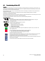
1
Warning and safety information
General information
WARNING
These devices are at hazardous voltage levels and control rotating mechanical parts, which in some circumstances, can be
dangerous. Non-observance of the warnings or non-compliance with the instructions in this manual can lead to danger to
life, serious injury or substantial damage to property.
Only qualified personnel who have previously familiarized themselves with all the instructions regarding safety, installation,
operating and maintenance as set out in this manual are permitted to work on these devices. Successful and safe
operation of these devices depends on their proper mounting, operation and maintenance.
The line supply, direct current and motor terminals as well as the brake and thermistor cables are at hazardous voltage
levels even when the inverter is out of service. Once the power supply has been disconnected, wait at least 5 minutes until
the device has discharged itself. Only then can you start the installation work.
Since the fault current for this product can be greater than 3.5 mA AC, a fixed ground connection is required and the
minimum size of the protective conductor must comply with local safety regulations for equipment with a high leakage
current.
It is strictly prohibited for any mains disconnection to be performed on the motor-side of the system; any disconnection of
the mains must be performed on the mains-side of the inverter.
Before the inverter power supply is connected, it must be ensured that the motor terminal box is closed.
If an LED or similar indicator does not light up or is not active when a function is switched from ON to OFF, this does not
mean that the unit has been switched off or is current-free.
The inverter must always be properly grounded.
The device must be isolated from the power supply before any connections at the device are established or changed.
Make sure that the inverter has been configured for the correct supply voltage. The inverter must not be connected to a
higher supply voltage.
The general and regional installation and safety regulations for working on equipment at high hazardous voltage levels
(e.g. EN 50178) as well as the relevant stipulations regarding the correct use of tools and personal protective equipment
(PPE) are especially to be observed.
CAUTION
Children and other unauthorized persons must be forbidden from accessing the devices!
It is only permissible to use these devices for the purpose specified by the manufacturer. Unauthorized changes and the
use of spare parts and accessories which are not sold or recommended by the manufacturer of the device can lead to fires,
electric shock and injuries.
NOTICE
This manual is to be kept somewhere close to the devices and must be easily accessible for all users.
If measurements or tests have to be carried out on the live device, the stipulations of safety regulation BGV A2 are to be
complied with, especially § 8 "Permissible deviations during work on live parts". Suitable electronic tools are to be used.
Before mounting and commissioning, please read these safety instructions and the warnings carefully as well as the
warning labels on the devices. It must be ensured that the warning labels are always legible; any signs that are damaged
or missing are to be replaced.
Make sure that suitable circuit breakers/fuses (with the specified rated currents) are installed between the line supply and
the inverter.
The manual is intended for users who have experience in handling the following equipment:
- PLCs
- STARTER commissioning software
- PROFIdrive profile and protocols.
The commissioning instructions in this manual only apply to standard inverters. The fail-safe commissioning is described in
the operating instructions.
2
CU230P-2 Control Units, Getting Started
A5E02484096, 05/2009
2
Documentation for additional support
Commissioning using "Getting Started"
Getting Started describes how you can perform basic commissioning with either STARTER or using the IOP. For special
inverter functions such as e.g. automatic restart or flying restart, please use the operating instructions, the Function Manual
and the parameter list.
The functions and properties of the IOP are described in detail in the "SINAMICS IOP" operating instructions and are only
explained here to an extent that is necessary to understand the described functions.
Collection of manuals for standard drives
The collection of manuals for standard drives is an extensive compilation of all documents relating to inverters, motors and
geared motors. It can be ordered as DVD and can run under all Windows versions.
Order No.: 6SL3298-0CA00-0MG0
Online documentation
In the Internet, the documentation for standard drives is available as PDF under the following link:
Online documentation for standard drives (http://support.automation.siemens.com/ww/view/en/4000024)
Generic station description files (GSD)
The generic station description files (GSD) for the standard drives are available in the Internet under the following link:
Generic station description files (http://support.automation.siemens.com/WW/view/en/23450835)
GSDs are required to integrate inverters into control systems (e.g. SIMATIC S7).
3
Installation
CU230 field of application
The CU230P-2 is a Control Unit that has been optimized for pumps and fans. It can be operated with all power units of the
PM240 and PM250 series.
The following versions of CU230P-2 are available:
● CU230P-2 HVAC
with RS485 interface for USS and Modbus RTU
● CU230P-2 CAN
with CANopen interface
● CU230P-2 DP
with PROFIBUS DP interface
They can be commissioned either using the STARTER commissioning software or using the optional IOP operator panel
(Intelligent Operator Panel).
You can save all the settings you enter during commissioning and operation to a memory card.
3.1
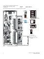
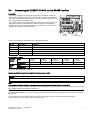
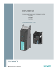
Interfaces, connectors, control terminals and LEDs on the CU
Overview
The CU controls the inverter functions. It cannot be used without a Power Module (PM) - just the same as a PM cannot be
used without a CU.
WARNING
Inverters are at hazardous voltage levels and control the speed and direction of rotation of motors. This is the reason that
only trained personnel may commission the inverters.
CU230P-2 Control Units, Getting Started
A5E02484096, 05/2009
3
Factory setting for command and setpoint sources
CU230P-2 HVAC and CU230P-2 CAN:
Terminals
(p0700 = p1000 = 2)
CU230P-2 DP:
Fieldbus
(p0700 = p1000 = 6)
The command and setpoint sources can be changed using p0700, or p1000.
ཱི
E:4 S C-V3N97875
s
SINAMICS
MICRO MEMORY CARD
6SL3254-0AM00-0AA0
00&VORW
ཱ
,23
,23KDQGKHOG
LQWHUIDFH
',3VZLWFKIRUWKHEXVDGGUHVV
&83'3&83&$1
ུ
ི
%LW
%LW
%LW
%LW
%LW
%LW
%LW
21
2))
&XUUHQW
1,
86%LQWHUIDFHIRU
67$57(5
1,',3VZLWFK
ཱུ
$,
$,
&XUUHQW9ROWDJH
',3VZLWFKIRU
DQDORJLQSXWV
ᆶ
5'<
%)
6WDWXV/('
ᆷ
ླྀ
'LJLWDORXWSXWV
ཹ
'HVLJQDWLRQRIWKHFRQWURO
WHUPLQDOV
&RQWUROWHUPLQDOEORFN
Figure
4
Control Unit CU230P-2, doors open
CU230P-2 Control Units, Getting Started
A5E02484096, 05/2009
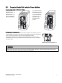
3.2
Snap the Control Unit onto the Power Module
Snap the Control Unit onto the Power Module
If you want to remove
the Control Unit, press
the unlatching button
on the Power Module
③. You can then tilt
the Control Unit
forwards and remove
it from the Power
Module.
Plug the Control Unit
onto the Power
Module as shown. All
the necessary
electrical connections
are made between
the two components.
Screening kit for the Control Unit
A screening kit is available for the Control Unit. This allows easy bonding of control
cable shields for connection to the Control Unit potential. The set must be attached
to the Control Unit by means of an M3 screw (supplied with the kit).
Regardless of whether or not a shield connection kit is used, the Control Unit is
connected to the reference potential of the Power Module as soon as it is snapped
onto the module.
Retain the shield connection kit
WARNING
If 230 V relays are controlled from the digital outputs DO0 and DO2, then these must always be switched into a no-voltage
condition before the Control Unit is removed from the Power Module. The reason for this is that when the Control Unit is
removed, the connection to the protective conductor is interrupted.
CU230P-2 Control Units, Getting Started
A5E02484096, 05/2009
5
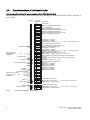
3.3
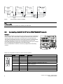
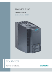
Control terminals of the Control Units
Arrangement and functions of the control terminals on the CU230P-2 Control Units
All Control Units have the same control terminals. The factory presettings for certain terminals differ, however, depending on
the CU variant.
7HUPLQDOV
7HUPLQDO
,QIRUPDWLRQ
GHVLJQDWLRQV
9,1
*1'
9287
*1'
1,$,
*1'
1,$,
$,
$,
2XWSXWFXUUHQW
6HWSRLQWLQSXWYLD
DQDORJVHWSRLQW
VWDQGDUG
99
$FWXDOIUHTXHQF\
'ULYHUHDG\
37&VHQVRURSWLRQDO
$2
$2*1'
9287
*1'
$,
$,
$2
$2*1'
$QDORJXH,Q2XW
$QDORJXH,Q2XW
*1'
'212
'2&20
37&
37&
9287
*1'
6LJQDO
$FWXDWRUIDXOW
6LJQDO
,QYHUWHURSHUDWLRQ
Figure
6
',
',
',
',
'LJLWDO,Q2XW
',&20
212))
5HYHUVLQJ
$FNQRZOHGJHIDXOW
))
6HWSRLQWLQSXWYLDIL[HG
IUHTXHQFLHV))))
))
DOWHUQDWLYH
))
([WHUQDO9
5HIHUHQFHSRWHQWLDOIRUWHUPLQDO
9YROWDJHRXWSXW
5HIHUHQFHSRWHQWLDOIRUWHUPLQDO
,QSXWIRUWHPSHUDWXUHVHQVRU1,RU$,
5HIHUHQFHSRWHQWLDOIRUWHUPLQDO
,QSXWIRUWHPSHUDWXUHVHQVRU1,RU$,
5HIHUHQFHSRWHQWLDOIRUWHUPLQDO
$QDORJLQSXWSRVLWLYH
$QDORJLQSXWQHJDWLYH
$QDORJRXWSXWSRVLWLYH9ಹ9P$ಹP$PD[˖
5HIHUHQFHSRWHQWLDOIRUWHUPLQDO
9RXWSXWZLWKRXWLVRODWLRQPD[P$
5HIHUHQFHSRWHQWLDOIRUWHUPLQDO
$QDORJLQSXWSRVLWLYH
$QDORJLQSXWQHJDWLYH
$QDORJRXWSXWSRVLWLYH9ಹ9P$ಹP$PD[˖
5HIHUHQFHSRWHQWLDOIRUWHUPLQDO
'LJLWDORXWSXW12FRQWDFW$9'&
'LJLWDORXWSXWFRPPRQFRQWDFW$9'&
0RWRUWHPSHUDWXUHVHQVRU37&.7<RUEHPHWDO1&
FRQWDFW
0RWRUWHPSHUDWXUHVHQVRU37&.7<RUEHPHWDO1&
FRQWDFW
,VRODWHG9RXWSXWPD[P$
5HIHUHQFHSRWHQWLDOIRUWHUPLQDO
',&20
'LJLWDOLQSXWLVRODWHG
'LJLWDOLQSXWLVRODWHG
'LJLWDOLQSXWLVRODWHG
'LJLWDOLQSXWLVRODWHG
'LJLWDOLQSXWLVRODWHG
'LJLWDOLQSXWLVRODWHG
',
',
'21&
'212
'2&20
'21&
'212
'2&20
'LJLWDORXWSXW1&FRQWDFW
'LJLWDORXWSXW12FRQWDFW
'LJLWDORXWSXWFRPPRQFRQWDFW
$9'&$9$&
'LJLWDORXWSXW1&FRQWDFW
'LJLWDORXWSXW12FRQWDFW
'LJLWDORXWSXWFRPPRQFRQWDFW
$9'&$9$&
Control terminals with pre-assignment
CU230P-2 Control Units, Getting Started
A5E02484096, 05/2009
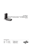
3.4
Connecting the CU230P-2 HVAC via the RS485 interface
Description
This section describes how the inverter is physically connected to a serial bus
system over the RS485 interface. The communication settings are described in
the Control Unit operating instructions in the sections "Communication over USS"
and "Communication over Modbus RTU".
The Control Unit has a two-part terminal strip underneath the Control Unit which
allows the inverter to be integrated into a serial bus system over the RS485
interface. This connector has short-circuit-proof, isolated pins. You will find the
terminal assignments in the following table.
Z
Y X
3LQ
56
FRQQHFWRU
3LQ
%XV
WHUPLQDWLQJVZLWFK
Table 1 Assignments for the terminal strip of the RS485 interface
Contact
Designation
Description
1
0V
Reference potential
2
RS485P
Receive and send signal (+)
3
RS485N
Receive and send signal (-)
4
Shield
Cable shield
5
---
---
Communication settings
Baud rate
p02020
USS
4 = 2400
9 = 57600
Modbus RTU
Address
p2021
5 = 4800
10 = 76800
6 = 9600
11 = 93750
7 = 19200
12 = 115200
5 = 4800
6 = 9600
7 = 19200
USS
0 … 30, factory setting = 8, maximum 31 Slaves
Modbus RTU
1 … 247, factory setting = 7, maximum 247 Slaves
8 = 38400
13 = 187500
Maximum cable length 1200 m (3281 ft)
General specifications and requirements for fault-free communication
NOTICE
When the bus is operating, the first and last bus station must be continuously connected to the supply.
Note
Communication with the controller, even when the supply voltage on the Power Module is switched off
You will have to supply the Control Unit with 24 V DC on terminals 31 and 32 if you require communication to take place with
the controller when the line voltage is switched off.
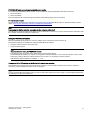
For the first and last stations, you must connect the bus terminating resistor using the DIP switches to the right of the RS485
terminal strip.
You can disconnect one or more slaves from the bus (by unplugging the bus connector) without interrupting the
communication for the other stations, but not the first or last.
CU230P-2 Control Units, Getting Started
A5E02484096, 05/2009
7
2))
7HUPLQDOV
&83
2))
/DVW56VODYH
&83
*
*
%XVWHUPLQDWLQJ
UHVLVWRU
&83
566ODYH
*
566ODYH
56
0DVWHU
7HUPLQDOV
21
7HUPLQDOV
6KLHOG
Figure
Communication network via RS485
Note
For Modbus RTU
Two 100-kΩ resistors are provided for polarizing the A&B cable.
3.5
Connecting CU230P-2 DP to the PROFIBUS DP network
Description
This section describes how the inverter is physically connected to a PROFIBUS
DP bus system. The communication settings are described in the Control Unit
operating instructions in the section "Communication over PROFIBUS DP".
The Control Unit CU230P-2 DP has a 9-pin sub D connector to the PROFIBUS
standard underneath the Control Unit for integrating the inverter into the
PROFIBUS DP fieldbus system. This connector has short-circuit-proof, isolated
pins. You will find the pin assignments in the following table.
Note: The PROFIBUS modules do not have any integrated bus terminating
resistors.
Z
Y X
6XE'FRQQHFWRU
Table 2 Pin assignments for the 9-pin sub D connector (socket)
8
Contact
Designation
Description
1
PE / shield
Ground connection
2
---
---
3
DPB
Data P receive/transmit (B/B’)
4
RTS
Control signal
5
0V
Reference potential for PROFIBUS data (C/C’)
6
5V
Supply voltage plus
7
---
---
8
DPA
Data N receive/transmit (A/A’)
9
---
---
Enclosure
PE / shield
Cable shield
CU230P-2 Control Units, Getting Started
A5E02484096, 05/2009
PROFIBUS DP cable connector and permissible cable lengths
For connecting the SINAMICS G120 inverter, we recommend the following PROFIBUS DP cable connectors:
● 6GK1 500-0FC00
● 6GK1 500-0EA02
They are equipped with a switch through which the bus terminating resistor can be connected.
Permissible cable lengths
The permissible cable lengths are dependent on the baud rate and the PROFIBUS cable. For further information, please
referto: (http://support.automation.siemens.com/WW/view/en/22698508)
Note
Communication with the controller, even when the line voltage is switched off
You will have to supply the Control Unit with 24 V DC on terminals 31 and 32 if you require communication to take place with
the controller when the line voltage is switched off.
Setting the PROFIBUS DP address
Before the PROFIBUS DP interface is used, the address of the node point (inverter) must be set.
The following methods are available for setting the PROFIBUS DP address:
● Using the address switch on the Control Unit
● Using parameter p0918
Note
Important notes for setting the PROFIBUS address
The address setting on the DIP switch takes priority over the p0918 settings.
The PROFIBUS DP address can only be set using p0918 when the address 0 is set on the DIP switches of the Control
Unit (factory setting). When the address switch is set to a value ≠ 0, the setting in p0918 is ignored.
Valid address range for Siemens controllers: 1 … 125.
Arrangement of the DIP switches on the Control Unit and address examples
The arrangement and the values of the individual DIP switches to set the Profibus address are provided in "Interfaces,
connectors, control terminals and LEDs on the CU (Page 3)
Note
A newly set PROFIBUS DP address will only come into effect after switching off and on again. It is particularly important that
any external 24 V supply is switched off.
CU230P-2 Control Units, Getting Started
A5E02484096, 05/2009
9
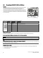
3.6
Connecting CU230P-2 CAN to CAN bus
Description
This section describes how the inverter is physically connected to the CAN bus.
The communication settings are described in the Control Unit operating
instructions in the section "Communication settings for CANopen".
The Control Unit CU230P-2 CAN has a 9-pin sub D connector underneath the
Control Unit for integrating the inverter into the CANopen fieldbus system. This
connector has short-circuit-proof, isolated pins. You will find the pin assignments
in the following table.
Z
Y X
68%'FRQQHFWRU
%XV
7HUPLQDWLQJVZLWFK
Table 3 Pin assignments for the 9-pin sub D connector (socket)
Contact
Designation
1
Reserved
---
2
CAN_L
CAN signal (dominant low)
CAN_GND
CAN ground
3
Description
4
Reserved
---
5
(CAN _SHLD)
Optional shield
6
(GND)
Optional CAN ground
7
CAN_H
CAN signal (dominant high)
8
Reserved
---
9
ISO
5V
CANopen cable connector
For setting up a CANopen network, you can use cable for serial 9-pin connections with sub D connectors.
General specifications for CANopen and requirements for fault-free communication
NOTICE
When the bus is operating, the first and last bus station must be continuously connected to the supply.
Note
Communication with the controller, even when the line voltage is switched off
You will have to supply the Control Unit with 24 V DC on terminals 31 and 32 if you require communication to take place with
the controller when the line voltage is switched off.
Setting the CANopen address
In order to integrate an inverter into a CANopen network, you need to set the address. The following possibilities exist:
● Using the address switch on the Control Unit
● Via parameter p8620
10
CU230P-2 Control Units, Getting Started
A5E02484096, 05/2009
Note
Important note for setting the CANopen address
The address can only be set via p8620 if the address 0 or 127 is set on the DIP switches of the Control Unit. If the
address switches are set to a value ≠ 0 or 127, this address is always active and p8620 is read-only.
Arrangement of the DIP switches on the Control Unit and address examples
The arrangement and the values of the individual DIP switches to set the CANopen address are provided in "Interfaces,
connectors, control terminals and LEDs on the CU (Page 3)
Note
A newly set CANopen address will only come into effect after switching off and on again. It is particularly important that any
external 24 V supply is switched off.
For additional information, please refer to the associated operating instructions:
CU230P-2 Control Units, Getting Started
A5E02484096, 05/2009
11
4
Commissioning
Description
Commissioning must have been completed before a motor can be operated at the inverter (Control Unit and Power Module).
To do this, proceed as follows:
● Commission the drive using either IOP or STARTER
● Download a valid parameter set via
– Memory card
– IOP
– STARTER
Further, the following prerequisites must be fulfilled to operate a motor from an inverter:
● The rated inverter current must, as a minimum, be just as high as that of the motor.
● The motor power should match that of the inverter, however, motors can be operated in the power range from
25 % … 100 % of the inverter power rating.
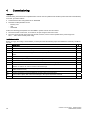
Installation checklist
Before you apply the voltage, check whether you have performed the following steps and whether the necessary conditions
are met.
Check item
✓
1
The ambient conditions specified for the motor and inverter have been complied with.
2
The inverter and motor are firmly installed.
3
The inverter and motor are correctly installed and the cooling measures are sufficient.
4
The motor and the associated application are ready for operation, i.e. in a safe state, the motor can
rotate.
5
The inverter is correctly grounded.
6
The supply voltage corresponds to the input voltage of the inverter.
7
The line fuses meet requirements and are correctly installed.
9
The motor and line connections are established and tightened according to guidelines.
10
The direction of rotation of the motor has been checked without it coupled to a machine - an incorrect
direction of rotation can result in serious material damage.
11
The motor cable is routed separately away from other cables (if required, shielded motor and control
cables should be used).
12
Control connections must be established corresponding to the regulations.
13
Tools or other objects that could cause damage to the system have been removed.
14
The inverter is the only current source for the motor.
12
CU230P-2 Control Units, Getting Started
A5E02484096, 05/2009
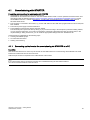
4.1
Commissioning with STARTER
Prerequisites and preparations for commissioning with STARTER
● STARTER has been installed on the commissioning PC
STARTER can be ordered under Order No. 6SL3072-0AA00-0AG0 as DVD or can be updated to the latest version from
the Internet under the following link (http://support.automation.siemens.com/WW/view/en/10804985/133100). Further,
the SINAMICS G120 PC - inverter connection kit - 2 (USB cable and STARTER DVD) is available under Order No.
6SL3255-0AA00-2CA0.
● The computer is connected to the inverter, e.g. via the USB cable and the USB driver (supplied with the Control Unit) has
been installed
● The inverter power supply has been switched on.
● The STARTER commissioning software has been started.
The online help also opens in the factory setting. If you proceed according to the description provided in Getting Started,
you can close the online help. If you wish to avoid that the online help is displayed each time the system starts, in the
"Options/Settings" dialog screen form, you can make the appropriate settings under the "Workbench" tab.
Commissioning is subdivided into the following steps.
● Creating a STARTER project
● Go online with the inverter
● Starting commissioning
4.1.1
Connecting up the inverter for commissioning via STARTER at a PC
Description
This section describes how to connect up the inverter via the USB interface for commissioning with STARTER. The USB
interface is located at the front of the Control Unit.
A Mini-B 5-pin connector is required for the USB interface at the inverter.
Note
If no IOP is inserted, then a connection to the PC can be established using the free RS232 interface.
You cannot use both interfaces at the same time.
CU230P-2 Control Units, Getting Started
A5E02484096, 05/2009
13
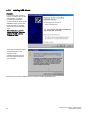
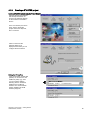
4.1.2
Installing USB drivers
Description
If you connect your inverter to
your PC for the first time via the
USB interface, you will be
prompted by the following
screen to install the driver for the
SINAMICS G120 Control Unit.
Insert the driver CD supplied
with the CU into the CD-ROM
drive.
Before installation, read the
license conditions. These are
saved on the CD under the
"License.txt" name.
Then click on "Next" and select
"Continue Anyway" in the
adjacent screen.
Installing the driver does not
have any negative impact on
your computer.
The driver has now been installed and you can start to create a STARTER project.
14
CU230P-2 Control Units, Getting Started
A5E02484096, 05/2009
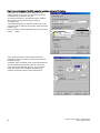
4.1.3
Creating a STARTER project
Create a STARTER project using the Project Wizards
Start the Wizards (Project/New
with wizard) and search, as
shown in the adjacent diagram,
for the inverters connected to
the PC.
In the next window (not shown
here), enter a descriptive
project name and if required,
also a comment.
Click on "Next" and the
adjacent dialog box is
displayed from where you can
configure the PC interface.
Setting the PC interface
If the Access Point "S7ONLINE
(STEP7)" is connected to "PC
COM-Port (USS)" (①), then
you can continue with the
following section. Otherwise,
install the "PC COM-Port
interface" as it is described in
Section Installing the COM
interface (Page 30).
CU230P-2 Control Units, Getting Started
A5E02484096, 05/2009
15
You will require the number of the COM connection to continue setting the PC interface.
A description is provided in Section Setting the COM
interface (Page 31) as to how you can read this from the
control panel and if required, change it.
To set the PC interface, in the adjacent screen, select the
"PC COM-Port (USS)" interface (①) and click on
"Properties" (②).
In the following dialog box, select the number of the COM
connection that you defined in the Section "Setting the COM
interface" (①).
Note: The number of the COM interface must be less than 8
(COM1 … COM7).
Using "Read" (②) check the baud rate that has been
selected and select the result (③) using the select box for
the baud rate (④).
In addition, select "Automatic mode" under the "RS485" tab.
This means that the PC interface has been set and you
return to the Project Wizards with "OK". If you press the
"Next" button there, then STARTER searches for the
inverters connected to the PC via the USB interface.
16
CU230P-2 Control Units, Getting Started
A5E02484096, 05/2009
In this window, press the "Continue" button - a dialog
box is displayed with a summary of the settings that
you made. Close the Project Wizards using the
"Finish" button and then you can continue with the
remaining commissioning steps.
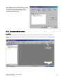
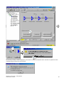
4.1.4
Go online with the inverter
Description
When the Project Wizards are exited, the project is set-up under the specified path and is simultaneously opened.
The following screenshot shows which button you must press to directly access the inverter data via STARTER (going
online).
*RLQJ2QOLQH
,QYHUWHUPRGH
2IIOLQH2QOLQH
CU230P-2 Control Units, Getting Started
A5E02484096, 05/2009
17
If the data that are saved in
STARTER for the inverter involved
(offline data) are different from those
of the inverter (online data), then the
adjacent screen is displayed.
First, press the "Load HW
configuration to PG" button to
overwrite the offline data with the
data of the inverter and then the
"Close" button and proceed with the
commissioning.
Note
If you first press the "Close" button, then the online connection is terminated before any data has been changed.
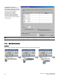
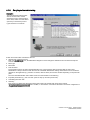
4.1.5
Start commissioning
Description
After you have gone online, open the commissioning dialog box with the following steps:
18
CU230P-2 Control Units, Getting Started
A5E02484096, 05/2009
The following message could be displayed if your inverter is not part of a SIMATIC control. This has no significance when
commissioning the inverter and can be closed.
CU230P-2 Control Units, Getting Started
A5E02484096, 05/2009
19
4.1.6
Carrying out commissioning
Description
The Commissioning Wizard starts
with the screen form to set the
closed-loop control. Using the dropdown menu, select one of the listed
open-loop or closed-loop control
types and click on "Continue".
Screen forms then follow one after the other for
● Setpoint and command sources
Note: For CU230P-2 DP CUs, the PROFIdrive telegram must be changed to 999 before the command and setpoint
sources can be changed.
● Motor type
● Motor data
● Drive functions
For the drive functions, the motor data identification type can be selected. We recommend that the motor data
identification is always carried out with the motor at a standstill. Whether the rotating measurement can be carried out
depends on the application (e.g. direction of rotation, distance limits) and must be decided depending on the particular
plant.
The motor data identification starts with the first ON command after commissioning.
● Important parameters (e.g. max. and min. speed or ramp-up and ramp-down time)
● Calculating the motor data
● Summary
This screen form allows the settings that have been made to be permanently saved in the inverter
) and in addition, to save them in a text file via the buffer. The device configuration is
(
completed with "Finish".
20
CU230P-2 Control Units, Getting Started
A5E02484096, 05/2009
The next ON command starts the motor data identification. This completes the first commissioning.
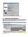
4.2
Restoring the factory settings using STARTER
The inverter is reset to the delivery condition by restoring the parameters to the factory setting.
Note
The reset operation is not applied to parameters p0014, p0100, p0201, p0205 or the communication parameters. Motor
parameters p0300 ... p0311 are suitably preassigned for the power unit.
The inverter must be in the online mode to "Restore factory setting". Communication with the control is interrupted for the
time it takes to restore the factory settings.
Restoring the factory setting is done in the following steps:
● Select the inverter in the directory tree
● Start "Restore to factory settings"
5HVHWWRIDFWRU\
VHWWLQJV
2QOLQHPRGH
UHTXLUHG
CU230P-2 Control Units, Getting Started
A5E02484096, 05/2009
21
4.3
Commissioning with the IOP
Description
Using a text and graphic display, the IOP offers the possibility of selecting Wizards for commissioning, function menus, e.g.
for diagnostics or the status display. It has five function keys and a navigation wheel that is simultaneously used as the OK
key. The IOP can also be used as handheld terminal.
The IOP display goes dark if a key is not pressed within 60 seconds. The display is re-activated if a key is pressed or the
navigation wheel is turned.
Using the IOP, prompted commissioning is possible just the same as setting individual parameters or standard
commissioning using parameter download.
Getting Started describes selecting the Commissioning Wizards and setting the setpoint input via the analog input or as fixed
frequencies via three digital inputs using the basic commissioning Wizards.
You will find a detailed description of all IOP functions in the associated operating instructions.
Important IOP symbols
Manual/Auto
The symbol indicates whether operator control is realized using the IOP (Manual) or using the
command and setpoint sources (Auto) that have been set for operation
Off / Operation / Fault
The inverter state is displayed using these symbols
Functions of the navigation wheel
● Selecting Wizards and menus by rotating
● Selecting Wizards and menus by pressing
● Changing values by rotating
● Accepting values by pressing
ON command for the inverter when using the IOP (Manual) for operator control, no function in the
"Auto" operating mode.
OFF command for the inverter when controlled from the IOP (Manual)
● OFF 1 (deceleration along the ramp) when pressed normally,
● OFF2 (pulse inhibit) when pressed for longer than 3 seconds.
This has not function in the "Auto" mode.
If this key is briefly pressed, then the display goes to the data previously displayed. if this key is press
for longer than three seconds, then the status display is shown. If the key is pressed when a
numerical value is entered, the actual value is not accepted.
Switching over between operator control from the IOP and via the command and setpoint sources that
have been set for operation
The information button provides additional information about the actual display.
22
CU230P-2 Control Units, Getting Started
A5E02484096, 05/2009
Commissioning with the IOP
For commissioning, the IOP must either be directly plugged onto the Control Unit
of the inverter or must be connected to it via the handheld enclosure. This
therefore establishes all of the connections required.
Plug the IOP onto the inverter
After you have connected-up the Control Unit, locate the lower edge of the IOP,
as shown in the diagram, onto the protruding lower section of the Control Unit
(①) and snap the IOP (②) onto the Control Unit.
Removing the IOP from the inverter
By pressing the interlocking knob (③), you release the mechanical connection to
the control module (Control Unit) and you can then remove the IOP.
The IOP can be inserted and removed also under voltage without any
restrictions.
Prerequisites for commissioning using the IOP
● The IOP is plugged onto the inverter.
● The inverter power supply has been switched on.
4.3.1
Commissioning with the IOP
Description
When you plug the IOP onto the inverter for the first time, then it logs-on with the English welcome screen and then goes
into the language selection menu.
Using the navigation wheel, select the language that you wish to use and acknowledge this by briefly pressing (OK or accept
function). The IOP then changes into the status display (standard display of the IOP).
For commissioning, select the Wizards using the navigation wheel and acknowledge with OK.
For basic commissioning, you can select one of the following Wizards using the navigation wheel:
● Basic commissioning
General basic commissioning
● Open-loop controlled fan
Basic commissioning for a fan without control loop
● Closed-loop controlled fan
Basic commissioning for a fan with control loop
● Open-loop controlled pump
Basic commissioning for a pump without control loop
● Closed-loop controlled pump
Basic commissioning for a pump with control loop
● Open-loop controlled compressor
Basic commissioning for a compressor without control loop
● Closed-loop controlled compressor
Basic commissioning for a compressor with control loop
● Roller conveyor
Basic commissioning for roller conveyors
CU230P-2 Control Units, Getting Started
A5E02484096, 05/2009
23
Note
Restoring to the factory setting during commissioning
As a first step in the basic commissioning, the Wizard offers "Restore factory setting". This option is always practical if, under
certain circumstances, your Control Unit was used in other applications and you are not completely certain which settings
were made at the CU.
Changing numerical values from the IOP
Numerical values are changed digit-by-digit in the IOP. The presently selected digit is changed by turning the navigation
wheel and is accepted by pressing OK; the next digit (to the right) is selected at the same time. Every numerical value must
be accepted digit by digit by pressing OK, even if a value is not changed.
The display jumps to the next numerical value if the last digit of a number is accepted with OK.
The ESC key can be used to jump back to the previous value if an incorrect value is entered.
Once basic commissioning has been completed, a summary of the settings is provided under the title "Summary of settings".
Using the navigation wheel, scroll in this screen until "Continue". If you acknowledge this with OK, you change into a screen
that allows you to select either "Save" or "Cancel Wizard". If you press Save, your settings are saved in a non-volatile
fashion and the "Settings saved successfully" message is displayed. Acknowledge this message with OK. Then, when
switching-on for the first time, depending on the entries you made, the motor data identification is performed or the motor
rotates corresponding to the values that have been set.
After the basic commissioning, you can additionally set a voltage boost for starting and a PID controller using the following
Wizards.
● Boost
Voltage boost
● PID Wizard
24
PID controller
CU230P-2 Control Units, Getting Started
A5E02484096, 05/2009
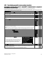
4.3.2
Commissioning example for inverter operation via terminals
Basic commissioning for inverter operation via terminals - example ON/OFF via digital input 0, setpoint via analog setpoint or
fixed frequencies, no supplementary setpoint
Commissioning using the "Basic commissioning" Wizards is executed in the subsequently listed steps:
The steps to enter the setpoint via an analog input are selected to the right in the table under 1; those steps that are required
to enter a setpoint via fixed frequencies are listed under 2.
Commissioning step
Type
1
2
Restoring the factory settings (Yes / No) - select and confirm with OK
Selection
X
X
Control mode: Selection options under various open-loop and closed-loop control variants - select
and confirm with OK
Selection
X
X
Encoder: Control Unit does not support an encoder - confirm with OK
Information
X
X
Encoder pulses, input not possible - confirm with OK
Information
X
X
Motor data (switch over to HP and 60 Hz line frequency not supported for this inverter) -> confirm
with OK
Information
X
X
Characteristic(50 Hz / 87 Hz) confirm with OK
Selection
X
X
Motor must be connected in the star configuration - confirm with OK
Information
X
X
Rated motor output
Setting
X
X
Rated motor speed
Setting
X
X
Rated motor current
Setting
X
X
Rated motor voltage
Setting
X
X
Motor data identification (none / calculate all parameters at standstill / calculate all parameters
plus saturation curve (motor rotating))
Selection
X
X
X
Caution:
It is not permissible to predict the direction of rotation and speed. This is the reason that it must be
decided on the system side as to whether this type of motor data identification can be selected!
Select command source "Terminal" , confirm with OK
Selection
X
Select main setpoint source "Analog setpoint" , confirm with OK
Selection
X
Select main setpoint source "Fixed frequency" , confirm with OK
Selection
Supplementary setpoint source (for the example, select "No additional setpoint") confirm with OK
Selection
X
X
Minimum speed
Setting
X
X
Ramp-up time
Setting
X
X
Ramp-down time
Setting
X
X
"Summary of settings". Select "Continue", confirm with
OK
Selection
X
X
Selection
X
X
X
X
X
Note
If you select another item in this menu and confirm with
"OK", then the Wizard brings you to this point in the
basic commissioning and the commissioning steps are
run through once again from this point onwards.
Select "Save", confirm with OK
The data save progress is displayed using a progress bar. Acknowledge the "Settings saved
successfully" message with OK.
Confirm the following screen display for motor data identification with OK.
CU230P-2 Control Units, Getting Started
A5E02484096, 05/2009
25
Commissioning step
Type
Setting values for the fixed frequencies
Selection
1
2
X
In order to enter a setpoint via the fixed frequencies, you must now assign digital inputs DI3, DI4
and DI5 to frequencies. You can switch-in the fixed frequencies either individually or together (the
values are added).
To set the fixed frequencies, go the menu by selecting "Menu / Parameter / Search by number" to
select individual parameters. There, select parameter p1001 (enter 01001). Select the parameter
with OK, with an additional OK, change into the value level and enter the required value using the
navigation wheel and confirm this with OK. Select and change parameters p1002 and 1003 one
after the other (factory setting = 0). After making the setting, press the ESC key until you reach the
status display. The value in p1001 is the fixed frequency for DI3, p1002 for DI4, p1003 for DI5.
If you did not select motor data identification, then commissioning has now been completed and
you can start the motor by issuing an ON command.
Information
X
X
If you have selected a variant of the motor data identification, then this is started with the next ON
command. In this case, commissioning has been completed after the motor data identification.
Note
If you do not make an entry for longer than 60 seconds, the IOP exits the Commissioning Wizards and returns to the status
display with the settings that you have made.
4.4
Restoring the factory settings using the IOP
The inverter is reset to the delivery condition by restoring the parameters to the factory setting.
Note
The reset operation is not applied to parameters p0014, p0100, p0201, p0205 or the communication parameters. Motor
parameters p0300 ... p0311 are suitably preassigned for the power unit.
Reset is selected using the navigation wheel on the IOP via "Menus/Parameters/Restore drives to factory setting" and then
started by pressing "OK".
After the reset, the display first jumps into the parameter window from where the reset was started. You can return to the
status display by pressing the "ESC" key twice.
4.5
Additional setting options for the inputs and outputs
Adapting the functions of the input and output terminals
The functions of the individual terminals can be adapted using interconnection and adjustable parameters. The number
ranges for the individual inputs and outputs are subsequently listed. In the IOP, you can call the individual parameters via
"Menu/Parameter/Search by number" and then you will obtain information texts by pressing the "INFO" button.
Parameters to change the functions of the inputs and outputs
● Digital inputs:
p0701 to p0724
● Digital outputs:
p0730 to p0748
● Analog inputs:
r0751 to p0762
● Analog outputs:
p0771 p0785
If you use Starter, then you can make the changes using the "Inputs and outputs" menu.
26
CU230P-2 Control Units, Getting Started
A5E02484096, 05/2009
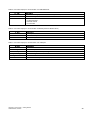
5
Technical data
Characteristic
Data
Operating voltage
24 V DC from the Power Module or an external 24 V DC supply (20.4 V to 28.8 V, 0.5 A) over
control terminals 31 and 32
Open-loop/closed-loop
control procedure
V/f control, output frequency between 0 Hz and 650 Hz:
● Linear V/f control,
● Linear V/f control with FCC,
● Linear V/f control with ECO mode,
● Quadratic V/f control,
● Multipoint V/f control,
● V/f control for applications in the textile industry,
● V/f control with FCC for applications in the textile industry,
● V/f control with independent voltage setpoint,
Vector control, output frequency between 0 Hz and 200 Hz:
● Speed control without encoder
● Torque control without encoder
Fixed frequencies
16, parameterizable
Skip frequencies
4, parameterizable
Setpoint resolution
0.01 Hz digital; 0.01 Hz serial; 10 bit analog
(motorized potentiometer 0.1 Hz [0.1% in PID mode])
Digital inputs
(dependent on the CU
type)
Up to 6 digital inputs, isolated; SIMATIC-compatible,
Low < 5 V, High > 10 V, maximum input voltage 30 V, switchable via terminals
- PNP Jumper terminal 69 with terminal 9
- NPN: Jumper 69 with terminal 28,
Notice! Either PNP or NPN must be jumpered in order that the inverter can function
Analog inputs
● 2 switchable (current/voltage), both configurable as additional digital inputs.
0 V to 10 V, 0 mA to 20 mA and -10 V to +10 V (AI0)
0 V to 10 V and 0 mA to 20 mA (AI1)
● 1 switchable (current / Ni1000) (AI2)
0/4 mA … 20 mA
NI1000: - 50°C … 150 °C
PT1000: - 50 °C … 250 C
● 1 fixed (NI1000, PT1000) (AI3)
NI1000: - 50°C … 150 °C
PT1000: - 50 °C … 250 C
Relay outputs
3, parameterizable
● DO1: 30 V DC / 0 A to 5 A (resistive load), 250 V AC / 2 A
● DO2: 30 V DC / 0 A to 0,5 A (resistive load)
● DO3: 30 V DC / 0 A to 5 A (resistive load), 250 V AC / 2 A
Analog outputs
2, parameterizable: 0 mA … 20 mA, 0 V … 10 V (AO0, AO1)
Dimensions (WxHxD)
73 mm x 199 mm x 65.5 mm
Weight
0.61 kg
Operating temperature
- 10°C … +60 °C (possible restrictions as a result of the Power Module should be observed)
Storage temperature
- 40°C … +70 °C
Humidity
< 95 % RH, non-condensing
Note
As far as the environmental requirements are concerned, possible restrictions resulting from the permissible values for the
power module must be taken into account.
The control terminals on the Control Unit are galvanically isolated from the supply voltage (PELV).
CU230P-2 Control Units, Getting Started
A5E02484096, 05/2009
27
6
Diagnostics
Options to display the state
Extraordinary inverter states are displayed using fault and alarm messages. An overview of all of the possible alarms and
faults is provided in Chapter 3 of the list manual.
The inverter provides the following options to display the state:
● LED - via the Control Unit
You will find details in the next section.
● Alarm and fault numbers via IOP and STARTER
You will find detailed descriptions on the alarm and fault numbers in the corresponding online help or in the List Manual.
● Diagnostic parameters via a control
Fault display on a higher-level control system
6.1
Operating states indicated on LEDs
Operating states of the Control Unit displayed by LEDs
The Control Unit is equipped with two LEDs, RDY (Ready) and BF (Bus Fault) that display the inverter status by showing a
red or green steady or flashing light.
There are two main inverter states, i.e. power-up and operation.
● Power-up
During power-up, the inverter progresses through various states which are indicated by red flickering or flashing for brief
periods by the Ready and the Bus Fault LEDs. It is not possible to read the inverter's current state from these displays.
● Operation
The relevant inverter state in operation is displayed by the LED states described below.
Possible LED states
V
V
IODVKLQJUHG+]
IODVKLQJJUHHQ+]
VLQJOHIODVKUHG
VLQJOHIODVKJUHHQ
GRXEOHIODVKUHG
GRXEOHIODVKUHG
21UHG
21JUHHQ
IODVKLQJUHG+]
IODVKLQJJUHHQ+]
IODVKLQJUHG+]
IODVKLQJJUHHQ+]
/('GLVSOD\VIRULQYHUWHUDQGFRPPXQLFDWLRQ
$GGLWLRQDOVWDWXVGLVSOD\VIRUWKHRSHUDWRUSDQHO/('IRU&$1RSHQ
Table 4 LED display of inverter states
LED
28
Explanation
RDY
BF
ON - green
---
Ready for operation (no active fault)
2 Hz - red
---
General fault
0.5 Hz - green
OFF
Commissioning/reset to factory settings
CU230P-2 Control Units, Getting Started
A5E02484096, 05/2009
Table 5 LED status display for communication over PROFIBUS DP
BF LED
OFF
0.5 Hz - red
2 Hz - red
Explanation
Cyclic data exchange (or PROFIBUS not used, p2030 = 0)
Bus fault - configuration error
Bus fault
- no data exchange
- baud rate search
- no connection
Table 6 LED status display for communication via RS485 (USS and Modbus RTU)
BF LED
OFF
0.5 Hz - red
2 Hz - red
Explanation
Receive process data
Bus active - no process data
No bus activity
Table 7 LED status display for communication over CANopen
BF LED
Explanation
ON - red
No bus
ON - green
2.5 Hz - green
Bus state "Operational"
Bus state "Pre-Operational" (flashing)
Single flash - green
Bus state "Stopped"
Single flash - red
Alarm - limit reached
Double flash - red
Error event in control (Error Control Event)
CU230P-2 Control Units, Getting Started
A5E02484096, 05/2009
29
7
Appendix
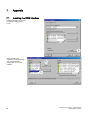
7.1
Installing the COM interface
Install the interface as shown in
the following dialog screen
forms.
After completing the
installation, close the window
and proceed with the
configuration of the COM
interface.
30
CU230P-2 Control Units, Getting Started
A5E02484096, 05/2009
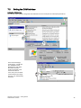
7.2
Setting the COM interface
Setting the COM interface
You can find, and if required, change the COM interface from the control panel as subsequently described.
In the Device Manager,
under "Ports", you will find
the "SINAMICS G120
Bridge Driver" and after it,
the COM connection
number in brackets. This
must be less than 8.
If not, then you must select
a free number in the range
from 0 to 7 as subsequently
described.
CU230P-2 Control Units, Getting Started
A5E02484096, 05/2009
31
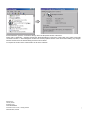
As described here, open the "Connection settings" tab in the Properties window of the driver.
There, click on "Extended ..." therefore opening the "Extended settings" screen form. In this screen form, select a free COM
connection number < 8. Acknowledge this screen form and the properties window of the driver without making any changes
with OK and then close the Device Manager and the Control Panel.
You require the number of the COM interface to set the PC interface.
Siemens AG
Industry Sector
Postfach 48 48
90026 NÜRNBERG
CU230P-2 Control Units, Getting Started
32
A5E02484096, 05/2009
CU230P-2 Control Units, Getting Started
A5E02484096, 05/2009