1
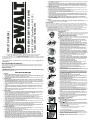
HEAVY DUTY XRP™ 32mm-65mm (1-1/4"-2-1/2")
16 GAUGE CORDLESS FINISH NAILERS
INSTRUCTION MANUAL
DC613-XE, DC615-XE, DC617-XE, DC618-XE, DC619-XE
f. Keep cutting tools sharp and clean. Properly maintained cutting tools with sharp cutting edges are less likely to
bind and are easier to control.
g. Use the power tool, accessories and tool bits etc., in accordance with these instructions and in the manner
intended for the particular type of power tool, taking into account the working conditions and the work to be
performed. Use of the power tool for operations different from those intended could result in a hazardous situation.
DEWALT Industrial Tool Co.,
701 East Joppa Road, Baltimore, MD 21286 • 20 Fletcher Road, Mooroolbark, VIC 3138 Australia
(FEB06) Form No. 625016-00 DC613-XE, DC615-XE, DC617-XE, DC618-XE, DC619-XE
Copyright © 2004, 2006 DEWALT
The following are trademarks for one or more DEWALT power tools: the yellow and black color scheme; the “D” shaped
air intake grill; the array of pyramids on the handgrip; the kit box configuration; and the array of lozenge-shaped humps
on the surface of the tool.
5. BATTERY TOOL USE AND CARE
a. Ensure the switch is in the off position before inserting battery pack. Inserting the battery pack into power
tools that have the switch on invites accidents.
b. Recharge only with the charger specified by the manufacturer. A charger that is suitable for one type of battery pack may create a risk of fire when used with another battery pack.
c. Use power tools only with specifically designated battery packs. Use of any other battery packs may create a
risk of injury and fire.
d. When battery pack is not in use, keep it away from other metal objects like paper clips, coins, keys, nails,
screws, or other small metal objects that can make a connection from one terminal to another. Shorting the
battery terminals together may cause burns or a fire.
e. Under abusive conditions, liquid may be ejected from the battery; avoid contact. If contact accidentally
occurs, flush with water. If liquid contacts eyes, additionally seek medical help. Liquid ejected from the battery
may cause irritation or burns.
6. SERVICE
a. Have your power tool serviced by a qualified repair person using only identical replacement parts. This will
ensure that the safety of the power tool is maintained.
Electrical Safety
The electric motor has been designed for one voltage only. Always check that the power supply corresponds to the
voltage on the rating plate. 240 V AC means your tool/charger will operate on alternating current. As little as 10% lower
voltage can cause loss of power and can result in overheating. All DEWALT tools are factory tested; if this tool does not
operate, check the power supply. Your DEWALT tool is double insulated, therefore no earth wire is required.
• Young children and the infirm. This appliance is not intended for use by young children or infirm persons without
supervision.Young children should be supervised to ensure that they do not play with this appliance.
• Replacement of the supply cord. If the supply cord is damaged, it must be replaced by the manufacturer or an
authorised DEWALT Service Centre in order to avoid a hazard.
FIG. A
CAUTION: Use only extension cords that are approved by the country’s Electrical
Authority. Before using extension cords, inspect them for loose or exposed wires,
damaged insulation and defective fittings. Replace the cord if necessary.
Important Safety Instructions for Nailers
FIG. B
FIG. C
FIG. D
IF YOU HAVE ANY QUESTIONS OR COMMENTS ABOUT THIS OR ANY DEWALT TOOL, CALL US AT: 1800 654 155 (Aust)
or 09 526 2556 (NZ).
SAFETY INSTRUCTIONS FOR POWER TOOLS
When using power tools, always observe the safety regulations applicable in your country to reduce the risk of fire,
electric shock and personal injury. Read the following safety instructions before attempting to operate this product.
Keep these instructions in a safe place.
FIG. E
General Safety Rules
WARNING! Read all instructions. Failure to follow all instructions listed below may result in electric shock, fire and/or
serious injury. The term “power tool” in all of the warnings listed below refers to your mains operated (corded) power tool
or battery operated (cordless) power tool.
SAVE THESE INSTRUCTIONS
1. WORK AREA
a. Keep work area clean and well lit. Cluttered and dark areas invite accidents.
b. Do not operate power tools in explosive atmospheres, such as in the presence of flammable liquids, gases
or dust. Power tools create sparks which may ignite the dust or fumes.
c. Keep children and bystanders away while operating a power tool. Distractions can cause you to lose control.
FIG. F
2. ELECTRICAL SAFETY
a. Power tool plugs must match the outlet. Never modify the plug in any way. Do not use any adapter plugs
with earthed (grounded) power tools. Unmodified plugs and matching outlets will reduce risk of electric shock.
b. Avoid body contact with earthed or grounded surfaces such as pipes, radiators, ranges and refrigerators.
There is an increased risk of electric shock if your body is earthed or grounded.
c. Do not expose power tools to rain or wet conditions. Water entering a power tool will increase the risk of electric shock.
d. Do not abuse the cord. Never use the cord for carrying, pulling or unplugging the power tool. Keep cord
away from heat, oil, sharp edges or moving parts. Damaged or entangled cords increase the risk of electric
shock.
e. When operating a power tool outdoors, use an extension cord suitable for outdoor use. Use of a cord suitable for outdoor use reduces the risk of electric shock.
FIG. G
3. PERSONAL SAFETY
a. Stay alert, watch what you are doing and use common sense when operating a power tool. Do not use a
power tool while you are tired or under the influence of drugs, alcohol or medication. A moment of inattention while operating power tools may result in serious personal injury.
b. Use safety equipment. Always wear eye protection. Safety equipment such as dust mask, non-skid safety
shoes, hard hat, or hearing protection used for appropriate conditions will reduce personal injuries.
c. Avoid accidental starting. Ensure the switch is in the off position before plugging in. Carrying power tools
with your finger on the switch or plugging in power tools that have the switch on invites accidents.
d. Remove any adjusting key or wrench before turning the power tool on. A wrench or a key left attached to a
rotating part of the power tool may result in personal injury.
e. Do not overreach. Keep proper footing and balance at all times. This enables better control of the power tool
in unexpected situations.
f. Dress properly. Do not wear loose clothing or jewellery. Keep your hair, clothing and gloves away from
moving parts. Loose clothes, jewellery or long hair can be caught in moving parts.
g. If devices are provided for the connection of dust extraction and collection facilities, ensure these are connected and properly used. Use of these devices can reduce dust related hazards.
4. POWER TOOL USE AND CARE
a. Do not force the power tool. Use the correct power tool for your application. The correct power tool will do
the job better and safer at the rate for which it was designed.
b. Do not use the power tool if the switch does not turn it on and off. Any power tool that cannot be controlled
with the switch is dangerous and must be repaired.
c. Disconnect the plug from the power source before making any adjustments, changing accessories, or storing power tools. Such preventive safety measures reduce the risk of starting the power tool accidentally.
d. Store idle power tools out of the reach of children and do not allow persons unfamiliar with the power tool
or these instructions to operate the power tool. Power tools are dangerous in the hands of untrained users.
e. Maintain power tools. Check for misalignment or binding of moving parts, breakage of parts and any other
condition that may affect the power tools operation. If damaged, have the power tool repaired before use.
Many accidents are caused by poorly maintained power tools.
Extension Cords
FIG. H
FIG. I
FIG. J
FIG. K
WARNING: When using any nailer, all safety precautions, as outlined below, should
be followed to avoid the risk of death or serious injury. Read and understand all
instructions before operating the tool.
• Hold tool by insulated gripping surfaces when performing an operation
where hidden wiring may be contacted. Contact with a “live” wire will make
exposed metal parts of the tool “live” and shock the operator.
• Actuating tool may result in flying debris, collation material, or dust which
could harm operator’s eyes. The operator and all those persons in the general
area should wear safety glasses with permanently attached side shields.
Approved safety glasses are imprinted with the characters “Z87.1”. It is the
employer’s responsibility to enforce the use of eye protection equipment by the
tool operator and other people in the work area. (Fig. A)
• Always wear appropriate personal hearing and other protection during use.
Under some conditions and duration of use, noise from this product may contribute to hearing loss. (Fig. A)
• Disconnect battery pack from the tool whenever clearing a jam, performing
any maintenance or repair, moving the tool or when the tool is unattended.
• Do not remove, tamper with, or otherwise cause the tool, trigger, contact trip
lock-off, or contact trip to become inoperable. Do not tape or tie trigger or
contact trip in the on position. Do not remove spring from contact trip.
Uncontrolled discharge could result.
• Do not operate a tool if any portion of the tool, trigger, contact trip lock-off,
or contact trip is inoperable, disconnected, altered, or not working properly.
Damaged parts or missing parts should be repaired or replaced before use.
• Do not alter or modify the tool in any way.
• Always assume that the tool contains fasteners.
• Do not point the tool at co-workers or yourself at any time. No horseplay!
Work safe! Respect the tool as a working implement. (Fig. B)
• Keep bystanders, children, and visitors away while operating a power tool.
Distractions can cause you to lose control. When the tool is not in use, it
should be locked in a safe place out of reach of children.
• Do not carry the tool from place to place holding the trigger. Accidental
discharge could result.
• Always use contact trip lock-off when tool is not in immediate use. Using the
contact trip lock-off will prevent accidental discharge.
• Do not overreach. Maintain proper footing and balance at all times. (Fig. C)
• Use the tool only for its intended use. Do not discharge fasteners into open
air, concrete, stone, extremely hard woods, knots or any material too hard
for the fastener to penetrate. Discharged fasteners may follow unexpected
path and cause injury. (Figs. D, F)
• Do not use the body of the tool or top cap as a hammer.
• Always keep fingers clear of nail track of magazine to prevent injury from
inadvertent release of the pusher. (Fig. G)
• Refer to the Maintenance and Repairs sections for detailed information on
the proper maintenance of the tool.
• Always operate the tool in a clean, lighted area. Be sure the work surface is
clear of any debris and be careful not to lose footing when working in elevated
environments such as rooftops.
• Do not drive fasteners near edge of material. The workpiece may split causing
the fastener to ricochet, injuring you or a co-worker. Be aware that the nail may
follow the grain of the wood (shiner), causing it to protrude unexpectedly from
the side of the work material. Drive the chisel point of the nail perpendicular to
the grain to reduce risk of injury. (Figs. E, F, L)
• Keep hands and body parts clear of immediate work area. Hold workpiece
with clamps when necessary to keep hands and body out of potential harm. Be
sure the workpiece is properly secured before pressing the nailer against the
material. The contact trip may cause the work material to shift unexpectedly.
(Fig. G)
• Do not use tool in the presence of flammable dust, gases or fumes. The tool
may produce a spark that could ignite gases causing a fire. Driving a nail into
another nail may also cause a spark. (Fig. H)
• Keep face and body parts away from back of the tool cap when working in
restricted areas. Sudden recoil can result in impact to the body, especially
when nailing into hard or dense material. (Fig. I)
BUMP/SEQUENTIAL SELECTOR SWITCH
Sequential Action
(Fig. J)
• When using the tool in sequential action, do not actuate the tool unless the
tool is placed firmly against the workpiece.
Bump Action
(Fig. K)
• When using the tool in bump action, be careful of unintentional double fires
resulting from tool recoil. Unwanted fasteners may be driven if the contact trip
is allowed to accidentally re-contact the work surface.
TO AVOID DOUBLE FIRES:
• Do not engage the tool against the work surface with a strong force.
• Allow the tool to recoil fully after each actuation.
• Use sequential action trigger.
• When “bump” actuating the finish nailer, always keep tool in control.
Inaccurate placement of tool can result in misdirected discharge of a fastener.
• Do not drive nails onto the heads of other fasteners. Strong recoil, jammed
fasteners, or ricocheted nails may result. (Fig. L)
• Be aware of material thickness when using nailer. A protruding nail may
cause injury.
ANGLED 20˚
FIG. 1
E
STRAIGHT
D
C
D
E
F
F
A.
B.
C.
D.
Trigger
Contact trip lock-off
Depth adjustment wheel
Headlights/Low
battery indicator
E. Jam clearing latch
F. Contact trip
G. Magazine
K
A
B
H. Pusher
I. Bump/sequential
selector switch
J. Reversible suspension
hook
K. No-mar pad
L. No-mar tip storage
E
A
J
L
J
I
L
I
H
G
G
H
FIG. L
FIG. M
FIG. N
• DEPTH ADJUSTMENT: To reduce risk of serious injury from accidental actuation
when attempting to adjust depth, ALWAYS;
• Remove battery pack.
• Engage contact trip lock-off. (Fig. M)
• Avoid contact with trigger during adjustments.
• Do not drive nails blindly into walls, floors or other work areas. Fasteners driven
into live electrical wires, plumbing, or other types of obstructions can result in
injury. (Fig. N)
• Stay alert, watch what you are doing and use common sense when operating a
power tool. Do not use tool while tired or under the influence of drugs, alcohol,
or medication. A moment of inattention while operating power tools may result in
serious personal injury.
WARNING: Use of this product will expose you to chemicals known to the State of
California to cause cancer, birth defects and other reproductive harm. Avoid inhaling
vapors and dust, and wash hands after using.
• Avoid prolonged contact with dust from power sanding, sawing, grinding,
drilling, and other construction activities. Wear protective clothing and wash
exposed areas with soap and water. Allowing dust to get into your mouth, eyes,
or lay on the skin may promote absorption of harmful chemicals.
WARNING: Use of this tool can generate and/or disburse dust, which may cause
serious and permanent respiratory or other injury. Always use NIOSH/OSHA approved
respiratory protection appropriate for the dust exposure. Direct particles away from face
and body.
CAUTION: When not in use, place tool on its side on a stable surface where it will not cause a tripping or falling
hazard. Some tools with large battery packs will stand upright on the battery pack but may be easily knocked over.
• The label on your tool may include the following symbols. The symbols and their definitions are as follows:
V ................volts
A ..............amperes
Hz................hertz
W ..............watts
min..............minutes
..........alternating current
no..............no load speed
..........direct current
..............Class II Construction
............earthing terminal
..............safety alert symbol
.../min........revolutions per minute
BEFORE OPERATING THIS TOOL, CAREFULLY READ AND UNDERSTAND ALL INSTRUCTIONS IN THE “IMPORTANT
SAFETY INSTRUCTIONS” SECTION.
Important Safety Instructions for Battery Packs
Your tool uses a DEWALT battery pack. When ordering replacement battery packs, be sure to include catalog number
and voltage: Extended Run-Time battery packs deliver more run-time than standard battery packs. Consult the chart at
the end of this manual for compatibility of chargers and battery packs.
NOTE: Your tool will accept either standard or Extended Run Time battery packs. However, be sure to select proper
voltage. Batteries slowly lose their charge when they are not on the charger, the best place to keep your battery is
on the charger at all times.
The battery pack is not fully charged out of the carton. Before using the battery pack and charger, read the safety
instructions below. Then follow charging procedures outlined.
READ ALL INSTRUCTIONS
• Do not incinerate the battery pack even if it is severely damaged or is completely worn out. The battery pack
can explode in a fire.
• A small leakage of liquid from the battery pack cells may occur under extreme usage or temperature conditions. This does not indicate a failure. However, if the outer seal is broken and this leakage gets on your skin:
a. Wash quickly with soap and water.
b. Neutralize with a mild acid such as lemon juice or vinegar.
c. If battery liquid gets into your eyes, flush them with clean water for a minimum of 10 minutes and seek immediate medical attention. (Medical Note: The liquid is 25-35% solution of potassium hydroxide.)
• Charge the battery packs only in DEWALT chargers.
• DO NOT splash or immerse in water or other liquids.
• Do not store or use the tool and battery pack in locations where the temperature may reach or exceed 105°F
(40˚C)(such as outside sheds or metal buildings in summer).
DANGER: Never attempt to open the battery pack for any reason. If battery pack case is cracked or damaged, do not
insert into charger. Electric shock or electrocution may result. Damaged battery packs should be returned to service center for recycling.
NOTE: Battery storage and carrying caps areprovided for use whenever the battery is out of the tool or
charger. Remove cap before placing battery in charger or tool.
WARNING: Do not store or carry battery so that metal objects can contact exposed battery terminals. For example, do not place battery in aprons, pockets, tool boxes, product kit boxes, drawers,
etc., with loose nails, screws, keys, etc. without battery cap. Transporting batteries can possibly
cause fires if the battery terminals inadvertently come in contact with conductive materials such
as keys, coins, hand tools and the like. The US Department of Transportation Hazardous Material Regulations (HMR)
actually prohibit transporting batteries in commerce or on airplanes (i.e., packed in suitcases and carry-on luggage)
UNLESS they are properly protected from short circuits. So when transporting individual batteries, make sure that the
battery terminals are protected and well insulated from materials that could contact them and cause a short circuit.
CAUTION: Battery pack must be securely attached to tool. If battery pack is detached, personal injury may result.
The RBRC™ Seal
The RBRC™ (Rechargeable Battery Recycling Corporation) Seal on the nickel-cadmium battery (or
battery pack) indicates that the costs to recycle the battery (or battery pack) at the end of its useful
life have already been paid by DEWALT. In some areas, it is illegal to place spent nickel-cadmium
batteries in the trash or municipal solid waste stream and the RBRC program provides an environmentally conscious alternative.
RBRC™ in cooperation with DEWALT and other battery users, has established programs in the United
States to facilitate the collection of spent nickel-cadmium batteries. Help protect our environment and conserve natural
resources by returning the spent nickel-cadmium battery to an authorized DEWALT service center or to your local retailer
for recycling. You may also contact your local recycling center for information on where to drop off the spent battery.
RBRC™ is a registered trademark of the Rechargeable Battery Recycling Corporation.
Important Safety Instructions for Battery Chargers
SAVE THESE INSTRUCTIONS: This manual contains important safety instructions for battery chargers.
• Before using charger, read all instructions and cautionary markings on charger, battery pack, and product using
battery pack.
DANGER: 240 volts are present at charging terminals. Do not probe with conductive objects. Electric shock or electrocution may result.
WARNING: Do not allow any liquid to get inside charger. Electric shock may result.
CAUTION: To reduce the risk of injury, charge only DEWALT nickel cadmium rechargeable batteries. Other types of batteries may burst causing personal injury and damage.
CAUTION: Under certain conditions, with the charger plugged in to the power supply, the exposed charging contacts
inside the charger can be shorted by foreign material. Foreign materials of a conductive nature such as, but not limited to,
steel wool, aluminum foil, or any buildup of metallic particles should be kept away from charger cavities. Always unplug
the charger from the power supply when there is no battery pack in the cavity. Unplug charger before attempting to clean.
• DO NOT attempt to charge the battery pack with any chargers other than the ones in this manual. The charger
and battery pack are specifically designed to work together.
• These chargers are not intended for any uses other than charging DEWALT rechargeable batteries. Any other
uses may result in risk of fire, electric shock or electrocution.
• Do not expose charger to rain or snow.
• Pull by plug rather than cord when disconnecting charger. This will reduce risk of damage to electric plug and
cord.
• Make sure that cord is located so that it will not be stepped on, tripped over, or otherwise subjected to damage or stress.
• Do not use an extension cord unless it is absolutely necessary. Use of improper extension cord could result in
risk of fire, electric shock, or electrocution.
• An extension cord must have adequate wire size (AWG or American Wire Gauge) for safety. The smaller the
gauge number of the wire, the greater the capacity of the cable, that is 16 gauge has more capacity than 18 gauge.
When using more than one extension to make up the total length, be sure each individual extension contains at
least the minimum wire size.
Recommended Minimum Wire Size for Extension Cords
Total Length of Cord
25 ft.
50 ft.
75 ft.
100 ft.
125 ft.
150 ft.
175 ft.
7.6 m
15.2 m
22.9 m
30.5 m
38.1 m
45.7 m
53.3 m
Wire Size AWG
18
18
16
16
14
14
12
• Do not place any object on top of charger or place the charger on a soft surface that might block the ventilation slots and result in excessive internal heat. Place the charger in a position away from any heat source. The
charger is ventilated through slots in the top and the bottom of the housing.
• Do not operate charger with damaged cord or plug — have them replaced immediately.
• Do not operate charger if it has received a sharp blow, been dropped, or otherwise damaged in any way. Take
it to an authorized service center.
• Do not disassemble charger; take it to an authorized service center when service or repair is required.
Incorrect reassembly may result in a risk of electric shock, electrocution or fire.
• Disconnect the charger from the outlet before attempting any cleaning. This will reduce the risk of electric
shock. Removing the battery pack will not reduce this risk.
• NEVER attempt to connect 2 chargers together.
• The charger is designed to operate on standard household electrical power (240 Volts). Do not attempt to use
it on any other voltage. This does not apply to the vehicular charger.
Using Automatic Tune-Up™ Mode
The automatic Tune-Up™ Mode equalizes or balances the individual cells in the battery pack allowing it to function at
peak capacity. Battery packs should be tuned up weekly or after 10 charge/discharge cycles or whenever the pack no
longer delivers the same amount of work. To use the automatic Tune-Up™, place the battery pack in the charger and
leave it for at least 8 hours. The charger will cycle through the following modes.
1. The red light will blink continuously indicating that the 1-hour charge cycle has started.
2. When the 1-hour charge cycle is complete, the light will stay on continuously and will no longer blink. This indicates
that the pack is fully charged and can be used at this time.
3. Whenever the pack is left in the charger after the initial 1-hour charge, the charger will begin the automatic TuneUp™ Mode. This mode continues up to 8 hours or until the individual cells in the battery pack are equalized. The
battery pack is ready for use and can be removed at any time during the Tune-Up™ Mode.
4. Once the automatic Tune-Up™ Mode is complete the charger will transition to a maintenance charge; the indicator
light shuts off when the automatic Tune-Up™ Mode is complete.
SAVE THESE INSTRUCTIONS FOR FUTURE USE
Chargers
Your tool uses a DEWALT Charger. Your battery can be charged in DE WALT 1 Hour Chargers, 15 Minute Chargers or
Vehicular 12 volt charger. Be sure to read all safety instructions before using your charger. Consult the chart on the
back cover of this manual for compatibility of chargers and battery packs.
FIG. 2
15 MINUTE CHARGER
1 HOUR CHARGER
Charging Procedure
DANGER: 240 volts present at charging terminals. Do not probe with conductive objects. Danger of electric shock or
electrocution.
1. Plug the charger into an appropriate outlet before inserting battery pack.
2. Insert the battery pack into the charger. The red (charging) light will blink continuously indicating that the charging
process has started (Fig. 2).
3. The completion of charge will be indicated by the red light remaining ON continuously. The pack is fully charged and
may be used at this time or left in the charger.
Indicator Light Operation
PACK CHARGING...................
FULLY CHARGED...................
HOT/COLD PACK DELAY........
REPLACE PACK......................
PROBLEM POWER LINE........
Charge Indicators
Some chargers are designed to detect certain problems that can arise with battery packs. Problems are indicated by the
red light flashing at a fast rate. If this occurs, re-insert battery pack into the charger. If the problem persists, try a differ-
ent battery pack to determine if the charger is OK. If the new pack charges correctly, then the original pack is defective
and should be returned to a service center or other collection site for recycling. If the new battery pack elicits the same
trouble indication as the original, have the charger tested at an authorized service center.
HOT/COLD PACK DELAY
Some chargers have a Hot/Cold Pack Delay feature: when the charger detects a battery that is hot, it automatically starts
a Hot Pack Delay, suspending charging until the battery has cooled. After the battery has cooled, the charger automatically switches to the Pack Charging mode. This feature ensures maximum battery life. The red light flashes long, then
short while in the Hot Pack Delay mode.
PROBLEM POWER LINE
Some chargers have a Problem Power Line indicator. When the charger is used with some portable power sources such
as generators or sources that convert DC to AC, the charger may temporarily suspend operation, flashing the red light
with two fast blinks followed by a pause. This indicates the power source is out of limits.
LEAVING THE BATTERY PACK IN THE CHARGER
The charger and battery pack can be left connected with the red light glowing indefinitely. The charger will keep the battery pack fresh and fully charged.
NOTE: A battery pack will slowly lose its charge when kept out of the charger. If the battery pack has not been kept on
maintenance charge, it may need to be recharged before use. A battery pack may also slowly lose its charge if left in a
charger that is not plugged into an appropriate AC source.
Weak Battery Packs: Chargers can also detect a weak battery. Such batteries are still usable but should not be expected
to perform as much work. In such cases, about 10 seconds after battery insertion, the charger will beep rapidly 8 times
to indicate a weak battery condition. The charger will then go on to charge the battery to the highest capacity possible.
Preparing the Tool
NOTE: Bump action nailers are prohibited in some countries.
CAUTION: NEVER spray or in any other way apply lubricants or cleaning solvents inside the tool. This can seriously
affect the life and performance of the tool.
NOTE: The battery pack is not fully charged out of the carton. Follow instructions outlined (see Charging Procedures).
1. Read the Safety Instruction section of this manual.
2. Wear eye and ear protection.
3. Ensure magazine is empty of all fasteners.
4. Check for smooth and proper operation of contact trip and pusher assemblies. Do not use tool if either assembly is
not functioning properly. NEVER use a tool that has the contact trip restrained in the actuated position.
5. Keep tool pointed away from yourself and others.
6. Insert fully charged battery pack.
Using the Contact Trip Lock-off (Fig. 8, 9)
WARNING: Always wear eye and ear protection when operating tool.
Each DEWALT nailer is equipped with a contact trip lock-off (B) which when pulled downward with the lock symbol
showing as shown, prevents the tool from firing a nail.
FIG. 8
FIG. 9
Important Charging Notes
1. Longest life and best performance can be obtained if the battery pack is charged when the air temperature is
between 65°F and 75°F (18°- 24°C). DO NOT charge the battery pack in an air temperature below +40°F (+4.5°C),
or above +105°F (+40.5°C). This is important and will prevent serious damage to the battery pack.
2. The charger and battery pack may become warm to touch while charging. This is a normal condition, and does not
indicate a problem. To facilitate the cooling of the battery pack after use, avoid placing the charger or battery pack
in a warm environment such as in a metal shed, or an uninsulated trailer
3. If the battery pack does not charge properly:
a. Check current at receptacle by plugging in a lamp or other appliance
b. Check to see if receptacle is connected to a light switch which turns power off when you turn out the lights.
c. Move charger and battery pack to a location where the surrounding air temperature is approximately 65°F - 75°F
(18° - 24°C).
d. If charging problems persist, take the tool, battery pack and charger to your local service center.
4. The battery pack should be recharged when it fails to produce sufficient power on jobs which were easily done
previously. DO NOT CONTINUE to use under these conditions. Follow the charging procedure. You may also
charge a partially used pack whenever you desire with no adverse affect on the battery pack.
5. Under certain conditions, with the charger plugged into the power supply, the exposed charging contacts inside the
charger can be shorted by foreign material. Foreign materials of a conductive nature such as, but not limited to,
steel wool, aluminum foil, or any buildup of metallic particles should be kept away from charger cavities. Always
unplug the charger from the power supply when there is no battery pack in the cavity. Unplug charger before
attempting to clean.
6. Do not freeze or immerse charger in water or any other liquid.
WARNING: Don't allow any liquid to get inside charger. Electric shock may result. .
CAUTION: Never attempt to open the battery pack for any reason. If the plastic housing of the battery pack breaks or
cracks, return to a service center for recycling.
Installing and Removing the Battery Pack
CAUTION: Engage contact trip lock-off before removing or installing battery.
NOTE: Make sure your battery pack is fully charged.
To install the battery pack into the tool handle, align the base of the tool with the notch inside the tool’s handle and
slide the battery pack firmly into the handle until you hear the lock snap into place.
FIG. 3
FIG. 4
B
B
When the contact trip lock-off is folded in as shown, the tool will be fully operational. The contact trip lock-off should
always be locked off whenever any adjustments are made or when tool is not in immediate use.
NOTE: Tools equipped with selective actuation, when in bump fire mode will allow the motor to start upon trigger pull.
This is normal operation. The contact trip lock-off constrains the contact trip from discharging a nail.
Loading the Tool
CAUTION: Keep tool pointed in a safe direction when loading nails.
CAUTION: Never load nails with the contact trip or trigger activated.
CAUTION: Always remove battery pack before loading or unloading nails.
LOAD AND DRAW METHOD (FIG. 1)
1. Insert fasteners into the rear of the magazine (G).
2. Pull pusher (H) back until the nail follower falls behind the nails.
3. Release the pusher.
LOCK AND LOAD METHOD
CAUTION: Keep fingers clear of pusher to prevent injury.
CAUTION: The contact trip lock-off should always be locked off whenever any adjustments are made or when tool is
not in use.
1. Pull pusher back until it locks.
2. Insert fasteners into the rear of the magazine.
3. Push forward on the pusher until it releases and slides forward.
UNLOADING THE TOOL
CAUTION: The contact trip lock-off should always be locked off whenever any adjustments are made or when tool is
not in use.
1. Pull pusher back until it locks.
2. Tip the tool up until the nails slide freely out the back of the magazine
3. Open the jam clear door on the nosepiece to verify there are no nails remaining.
Adjusting Depth (Fig. 10)
The depth that the fastener is driven can be adjusted using the depth adjustment wheel (C) on the side of the tool.
WARNING: To reduce risk of serious injury from accidental actuation when attempting to adjust depth, ALWAYS:
• Remove battery pack.
• Engage contact trip lock-off.
• Avoid contact with trigger during adjustments.
1. To drive the nail shallower, rotate the depth adjustment wheel (C) counterclockwise. There are six depth settings,
1 being the shallowest and 6 being the deepest.
2. To sink a nail deeper, rotate the depth adjustment wheel (C) clockwise.
M
To remove the battery pack from the tool, press the release buttons (M) and firmly pull the battery pack out of the tool
handle. Insert it into the charger as described in the charger manual (Fig. 4).
FIG. 10
COMPONENTS
Refer to Figure 1 for a complete list of components.
D
OPERATION
C
Mode Selection
WARNING: Always wear eye and ear protection when operating tool.
The DEWALT cordless nailers are assembled in accordance with the ANSI Standard SNT-101-2002.
Before operating this tool, look at the selector switch to determine the actuation mode. Read all instructions before
selecting actuation mode.
Headlights (Fig. 10)
There is a headlight (D) located on each side of the nailer. Headlights turn on upon battery insertion, activation of the trigger,
or depressing the contact trip. The lights will automatically shut off after 10 seconds unless tool remains in use.
NOTE: These headlights are for lighting the immediate work surface and are not intended to be used as flashlights.
LOW BATTERY INDICATOR: The headlights will flash four consecutive times and then shut down to indicate low battery.
JAMMED NAIL INDICATOR: The headlights will flash continually if a nail becomes jammed in the nosepiece (see
Clearing a Jammed Nail).
• DEWALT cordless nailers DC613, DC615, DC617, and DC619 are ONLY capable of
operating in sequential action mode (Fig. 5).
SEQUENTIAL ACTION
Use sequential action for intermittent nailing where very careful and accurate placement is
desired.
To operate the nailer in sequential action mode:
1. Flip the switch located on the bodyof the tool just between the trigger and magazine to
the left, as shown in Figure 6.
2. Fully depress nosepiece against the work surface (motor will start).
3. Pull trigger (nail will drive into work surface).
4. Release trigger.
5. Lift nosepiece off work surface.
6. Repeat steps 2 - 4 for next application.
FIG. 5
Clearing a Jammed Nail (Fig. 11)
FIG. 6
CAUTION: The contact trip needs to be depressed followed by a trigger pull for each nail
followed by a release of both the contact trip and trigger after each nail.
• DEWALT cordless nailer DC618 is equipped with a bump/sequential selector switch
(Fig. 6).
BUMP ACTION
Bump action is intended for rapid nailing on flat, stationary surfaces.
When using bump action, two methods are available: place actuation and bump actuation.
Flip the switch located on the body of the tool just between the trigger and magazine to the right
as shown in Figure 7.
To operate the tool using the PLACE ACTUATION method:
If a nail becomes jammed in the nosepiece, keep the tool pointed away from you and follow FIG. 11
these instructions to clear:
1. Remove battery pack from tool and engage contact trip lock-off.
2. Pull the pusher back until it locks in place then remove the nails.
3. Lift the jam clearing latch (E) then pull up to open front door (O).
4. Remove bent nail, using pliers if necessary.
N
5. If driver blade is in the down position, insert screwdriver or other rod into nosepiece and
E
push driver blade back in position.
O
6. Close the front door and engage the wireform under the two arms (N) on the nosepiece.
Push latch until it locks in place.
7. Reinsert battery pack.
NOTE: The tool will disable itself and not reset until the battery pack has been removed and reinserted.
8. Reinsert nails into magazine (see Loading the Tool).
9. Release pusher.
NOTE: Should nails continue to jam frequently in nosepiece, have tool serviced by an authorized DEWALT service center.
Cold Weather Operation
FIG. 7
CAUTION: A nail will fire each time the trigger is depressed as long as the contact trip
remains depressed.
1. Depress the contact trip against the work surface.
2. Depress the trigger.
To operate the tool using the BUMP ACTUATION method:
1. Depress the trigger.
2. Push the contact trip against the work surface. As long as the trigger is depressed, the tool will fire a nail every
time the contact trip is depressed. This allows the user to drive multiple nails in sequence.
CAUTION: Do not keep trigger depressed when tool is not in use. Keep the contact trip lock-off engaged in the locked
position when the tool is not in use.
When operating tools at temperatures below freezing:
1. Keep tool as warm as possible prior to use.
2. Actuate the tool 5 or 6 times into scrap lumber before using.
Hot Weather Operation
Tool should operate normally. However, keep tool out of direct sunlight as excessive heat can deteriorate bumpers and other
rubber parts resulting in increased maintenance.
Suspension Hook (Fig. 12)
FIG. 12
The DEWALT cordless nailers include an integrated suspension hook (J) and can be attached to
either side of the tool to accommodate left- or right-handed users. If the hook is not desired at
all, it can be removed from the tool.
TO REMOVE SUSPENSION HOOK
1. Remove battery pack from tool.
2. To switch the tool from right- to left-hand usage simply remove the screw from the
opposite side of the tool and reassemble on the other side.
J
3. Replace battery pack.
WARNING: Remove nails from magazine before making any adjustments or servicing this tool. Failure to do so may
result in serious injury.
CAUTION: Disconnect battery pack from tool before making any adjustments, changing accessories, servicing, or
moving the tool. Such preventative safety measures reduce the risk of starting the tool accidentally.
CAUTION: When not in use, place tool on its side on a stable surface where it will not cause a tripping or falling
hazard. Some tools with large battery packs will stand upright on the battery pack but may be easily knocked over.
TO REPLACE RETURN CORD ASSEMBLY
NOTE: For correct cord position during assembly, refer to the proper orientation of the return cord assembly in Figure 15.
1. Align one of the rubber tabs (Y) from the new return cord assembly with the corresponding slot in the driver
(Fig. 18).
2. With your finger, push and bend the rubber tab around corner (Fig. 18) while pulling the rubber cord until tab is
firmly in place (Fig. 19).
FIG. 18
Y
FIG. 19
MAINTENANCE
Daily Maintenance Chart
ACTION
WHY
HOW
ACTION
WHY
HOW
Clean magazine, pusher, and contact trip mechanism.
Permits smooth operation of magazine, reduces wear, and prevents jams.
Blow clean with compressed air. The use of oils, lubricants periodically or solvents is not recommended
as they tend to attract debris.
Before each use, check to insure all screws, nuts and fasteners are tight and undamaged.
Prevents jams and premature failure of tool parts.
Tighten loose screws or other fasteners using the appropriate allen wrench or screwdriver.
3. Repeat above procedure for other rubber cord.
TO REASSEMBLE NAILER
1. Insert the tip of the driver/return assembly blade into the matching hole in the nosepiece (Fig. 20).
FIG. 20
FIG. 21
FIG. 22
Cleaning
Use only mild soap and a damp cloth to clean the tool. Many household cleaners contain chemicals which could
seriously damage plastic. Also, do not use gasoline, turpentine, lacquer or paint thinner, dry cleaning fluids or similar
products. Never let any liquid get inside the tool; never immerse any part of the tool into a liquid.
CHARGER CLEANING INSTRUCTIONS
WARNING: Disconnect the charger from the AC outlet before cleaning. Dirt and grease may be removed from the
|exterior of the charger using a cloth or soft non-metallic brush. Do not use water or any cleaning solutions.
Lubrication
CAUTION: NEVER spray or in any other way apply lubricants or cleaning solvents inside the
tool. This can seriously affect the life and performance of the tool.
DEWALT tools are properly lubricated at the factory and are ready for use. However, it is recommended that, once a year, you take or send the tool to a certified service center for a thorough
cleaning and inspection.
Repairs
To assure product SAFETY and RELIABILITY, repairs, maintenance and adjustment (including brush inspection and
replacement) should be performed by authorized service centers or other qualified service personnel, always using
identical replacement parts.
CAUTION: Disconnect battery pack from tool before making any adjustments, changing accessories, servicing,
or moving the tool. Such preventative safety measures reduce the risk of starting the tool accidentally.
CAUTION: Remove nails from magazine before making any adjustments or servicing this tool. Failure to do so may
result in serious injury.
TO SERVICE
1. Remove 3 T25 slotted screws from top cover. Remove cover
FIG. 13
from housing and set aside.
W
S
2. Using a nail or punch, apply pressure to the pin (Q) sliding the
R
pin out from the metal structure (Fig. 13).
V
U
3. Push driver/return assembly (R) toward nosepiece and hold in
place against the lower bumper (V) as you roll back the activation arm Assembly (S). Remove activation arm assembly and
set aside.
4. Use a flat blade screwdriver to pry up on the return cord assemQ
bly (T) until the detents release. Lift up to remove (Fig. 14).
FIG. 14
FIG. 15
DRIVER/RETURN ASSEMBLY
Available from DEWALT
T
5. Remove the driver/return assembly (Fig. 15).
6. Inspect lower bumper (V), upper bumper (X), and other surfaces for cracks or damage and replace if necessary
(Fig. 16). Replace damaged return cord assembly.
FIG. 16
FIG. 17
Y
X
V
FIG. 24
RETURN CORD ASSEMBLY
Available from DEWALT
Z
AA
BB
AA
2. Move contact trip (Z) to the side while pulling back on the return cord assembly (Fig. 21).
3. Engage the hooks (AA) on the return cord assembly to the notch (BB) in the metal structure then push down to
snap into detents (Fig. 22).
4. Slide the driver/return assembly (R) toward the nosepiece and hold.
5. Insert activiation arm assembly by first engaging the cam pin (U) to the solenoid; then align the pivot holes (W) to
the metal structure (Fig. 13).
6. Slide the pin (Q) through the metal structure, capturing the activation arm assembly and spring.
7. Ensure the activation arm is fully engaged as
FIG. 23
shown in Figure 23.
8. Replace the cover to housing, insert 3 T25
slotted screws and tighten.
Accessories
Recommended accessories for use with your tool
are available at extra cost from your local service
center. If you need any assistance in locating any
accessory, please contact DEWALT Industrial Tool
Co., 20 Fletcher Road, Mooroolbark, VIC 3138
Australia or call 1800 654 155.
CAUTION: The use of any other accessory not
recommended for use with this tool could be hazardous.
Guarantee
Applicable to hand held Power Tools, Lasers and Nailers.
Three Year Limited Warranty
DEWALT will repair, without charge, any defects due to faulty materials or workmanship for three years from the date of
purchase. Please return the complete unit, transportation prepaid, to any DEWALT Service Centre, or any authorised
service station.
For warranty repair information, call (AUS) 1800 654 155 or (NZ) 09 526 2556.
This warranty does not apply to
• Accessories
• Damage caused where repairs have been made or attempted by others.
• Damage due to misuse, neglect, wear and tear, alteration or modification.
This warranty gives you specific legal rights and you may have other rights under the provisions of the Consumer
Guarantee Act 1993 (New Zealand only), Trade Practices Act 1974 and State Legislation (Australia only).
In addition to the warranty, DEWALT tools are covered by our:
FREE ONE YEAR SERVICE CONTRACT
DEWALT will also maintain the tool for free at any time during the first year of purchase. This includes labour, parts and
lubrication required to restore the product to sound mechanical and/or electrical condition. Normal wear parts are not
covered in this service. Carbon brushes worn more then 50% will be replaced.
NOTE: Three Year Warranty is not applicable to items deemed as consumables. Radial arm saws are covered by a one
(1) year warranty only. DEWALT Reserves the right to review its warranty policy prior to launch of any new business
development products.
30 DAY NO SATISFACTION GUARANTEE
If you are dissatisfied with any DEWALT power tool, laser or nailer, for any reason, simply return it to the point of purchase with your sales receipt within 30 days for a replacement unit or a full refund.
FREE WARNING LABEL REPLACEMENT: If your warning labels (Fig. 24) become illegible or are missing, call (AUS)
1800 654 155 or (NZ) 09 526 2556 for a free replacement.
TOOL SPECIFICATIONS
DC613
Sequential
Multi (14.4 & 12)
12'' (305mm)
4.18'' (106mm)
12.75'' (324mm)
7.8lbs. (3.57kg)
Straight
Up to 110 Nails
Firing Mode
Voltage
Height
Width
Length
Weight
Magazine Angle
Loading Capacity
DC615
Sequential
Multi (14.4 & 12)
12.4'' (315mm)
4.18'' (106mm)
12.5'' (317mm)
7.8lbs. (3.57kg)
Angled 20˚
Up to 120 Nails
DC617
Sequential
18
12'' (305mm)
4.18'' (106mm)
12.75'' (324mm)
8.5lbs. (3.8kg)
Straight
Up to 110 Nails
DC618
Selective
18
12.4'' (315mm)
4.18'' (106mm)
12.5'' (317mm)
8.5lbs (3.8kg)
Angled 20˚
Up to 120 Nails
DC619
Sequential
18
12.4'' (315mm)
4.18'' (106mm)
12.5'' (317mm)
8.5lbs. (3.8kg)
Angled 20˚
Up to 120 Nails
NAIL SPECIFICATIONS
Angled
Straight
1-1/4'', 1-1/2", 1-3/4", 2", 2-1/2"
1-1/4'', 1-1/2", 1-3/4", 2", 2-1/2"
(32mm, 38mm, 44mm, 51mm, 65mm) (32mm, 38mm, 44mm, 51mm, 65mm)
16 gauge
16 gauge
20˚
0˚
Nail Lengths
Shank Diameters
Nail Stick Angles
TROUBLESHOOTING GUIDE
MANY COMMON PROBLEMS CAN BE SOLVED EASILY BY UTILIZING THE CHART BELOW. FOR MORE SERIOUS OR PERSISTENT PROBLEMS,
CONTACT A DEWALT SERVICE CENTER OR CALL 1800-654-155.
DISCONNECT BATTERY PACK FROM TOOL BEFORE ALL REPAIRS
SYMPTOM
Tool doesn’t turn on
(Headlights don’t turn on)
CAUSE
Low battery charge or damaged battery
Terminals are dirty or damaged
Contact trip lock is in a locked position
Bent contact trip
Tool internal electronics not reset
Damaged internal electronics
Motor stops running after 2 seconds
Contact trip or trigger not depressed
Damaged trigger
Bent contact trip
Contact trip lock in the locked position
(Sequential mode only)
Damaged internal electronics
Low battery charge or damaged battery
Jammed fastener
Tool doesn’t actuate
(Headlights on, motor does not run)
Tool doesn’t actuate (Headlights flash 4 times)
Tool doesn't actuate
FIX
Charge or replace battery
See authorized service center
Unlock contact trip lock
See authorized service center
Remove battery, wait 3 seconds and reinsert
See authorized service center
Normal operation; release trigger or contact trip and redepress
See instruction manual
See authorized service center
See authorized service center
Unlock contact trip lock
See authorized service center
Charge or replace battery
Remove the battery, clear the jammed fastener, (push driver blade
back up manually if necessary) and reinsert battery pack
See authorized service center
See authorized service center
Replace return system; see authorized service center
Clean nosepiece
Replace driver/return assembly; see authorized service center
Charge or replace battery
Rotate depth adjustment wheel to a deeper setting
See instruction manual
Choose appropriate material or fastener length
Jammed mechanism
Damaged internal electronics
Damaged return system
Debris in nosepiece
Damaged driver/return assembly
Low battery charge or damaged battery
Depth adjustment set too shallow
Tool not firmly applied to workpiece
Material and fastener length
too rigorous an application
Damaged or worn driver blade tip
Damaged or worn driver/return assembly
No fasteners in magazine
Wrong size or angle fasteners
Debris in nosepiece
Debris in magazine
Worn magazine
Damaged or worn driver blade
Damaged pusher spring
Wrong size or angle fasteners
Damaged or worn driver blade
Material and fastener length
too rigorous an application
Low battery charge or damaged battery
Debris in nosepiece
Debris in magazine
Worn magazine
Worn or damaged pusher spring
Tool doesn’t actuate (Headlights on, motor runs)
Tool doesn’t actuate
(Headlights on, motor runs, driver blade stuck down)
Tool operates, but does not drive the fastener fully
Tool operates, but no fastener driven
Jammed fastener
Replace driver/return assembly; see authorized service center
Replace driver/return assembly; see authorized service center
Load fasteners into magazine
Use only recommended fasteners
Clean nosepiece
Clean magazine
Replace magazine; see authorized service center
Replace driver/return assembly; see authorized service center
Replace spring; see authorized service center
Use only recommended fasteners
Replace driver/return assembly; see authorized service center
Material or fastener length inappropriate
Charge or replace battery
Clean nosepiece
Clean magazine
Replace magazine; see authorized service center
Replace spring; see authorized service center
DEWALT Battery and Charger Systems
Battery
Output
Nominal
Chargers/Charge Time
240 Volts
12 Volts
Cat. Number
Voltage
Amp Hour
97014
98014
DW9106
DW9107
DW9108
DW9115
DW9116
DW9117
DW9118
DE9116
DE9118
DW911
DC011
DW0245
DE2046
DW9109
DW0242
DE0240-XJ
DW0240
DW9096
DE9095-XJ
DE9091-XJ
DW9091
DC9071
DE9074-XJ
DW9072
DE9071-XJ
DW9071
DW9050
DW9063
DW9062
DW9061
DW9048
DW9057
DW9046
DC9096
DC9091
24
24
24
18
18
14.4
14.4
12
12
12
12
12
12
9.6
9.6
9.6
9.6
7.2
7.2
18
14.4
2.0
2.0
1.7
2.4
2.0
2.0
1.7
2.4
1.25
1.2
2.0
1.7
1.3
1.25
1.3
1.7
1.3
1.25
1.3
2.4
2.4
X
X
X
X
X
45
45
60
45
45
60
60
40
45
45
60
40
45
40
X
60
X
X
X
X
X
45
45
60
45
45
60
60
40
45
45
60
40
45
40
X
60
X
X
X
X
X
45
45
60
45
45
60
60
40
45
45
60
40
45
40
X
60
X
X
X
X
X
45
45
60
30
30
45
45
X
30
30
45
X
30
X
X
60
X
X
X
60
60
45
45
60
30
30
45
45
X
30
30
45
X
30
X
60
60
X
X
X
X
X
15
15
15
15
15
15
15
15
15
15
15
15
15
15
X
15
X
X
X
60
60
45
45
60
30
30
45
45
X
30
30
45
X
30
X
60
60
X
X
X
20
20
15
15
15
12
12
15
15
X
12
12
15
X
12
X
20
15
X
X
X
X
X
90
90
60
60
60
90
90
X
60
60
90
X
60
X
X
60
X
X
X
60
60
45
45
60
30
30
45
45
X
30
30
45
X
30
X
60
60
X
X
X
X
X
90
90
60
60
60
90
90
X
60
60
90
X
60
X
X
60
X
X
X
60
60
45
45
60
30
30
45
45
X
30
30
45
X
30
X
60
60
X
X
X
60
60
45
45
60
30
30
45
45
X
30
30
45
X
30
X
60
60
60
60
60
X
X
X
X
X
X
X
X
X
X
X
X
X
X
X
X
X
X
60
60
60
X
X
X
X
X
X
X
X
X
X
X
X
X
X
X
X
X
X
X
X
X
60
60
45
45
60
30
30
45
45
X
30
30
45
X
30
X
60
60
X Indicates that the battery pack is not compatible with that specific charger.
All charge times are approximate. Actual charge time may vary.
Read the instruction manual for more specific information.
The battery voltage is nominal, it can measure above or below depending on the state of charge.