1
aussenen.fm Seite 1 Mittwoch, 14. April 2004 1:21 13
É463 584 36 81hË
Order no. 6515 4058 02 Part no. 463 584 36 81 EN Edition D1, 01/04
G-Class Owner's Manual
G-Class Owner's Manual
Nur fuer internen Gebrauch
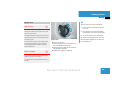
Thank you for choosing
Mercedes-Benz.
Before you drive off, get to know your
Mercedes-Benz and read this Owner's
Manual. This will help you to obtain the
maximum pleasure from your vehicle and
avoid endangering yourself and others.
Items of optional equipment are marked
with an asterisk *. The equipment in your
vehicle may vary, depending on the model,
availability and country specifications.
Mercedes-Benz is constantly updating its
vehicles to the state of the art and therefore reserves the right to introduce changes in design, equipment and technical
features at any time.
You cannot, therefore, base any claims on
the data, illustrations or descriptions in
this Owner's Manual.
The Owner's Manual, the brief instructions,
the "Services" booklet and the "Service
Centres" booklet are an integral part of the
vehicle. These should therefore always be
kept in the vehicle and passed on to the
new owner if you sell the vehicle.
Please consult a Mercedes-Benz Service
Centre if you have any questions.
The technical documentation team at
DaimlerChrysler AG wishes you safe and
pleasant motoring.
Nur fuer internen Gebrauch
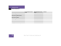
Contents
Introduction . . . . . . . . . . . . . . . . . . . . . 9
The aim of this manual . . . . . . . . . . . . . 9
Symbols . . . . . . . . . . . . . . . . . . . . . . . 11
Protection of the environment . . . . . . 12
Operating safety . . . . . . . . . . . . . . . . . 13
Correct use . . . . . . . . . . . . . . . . . . 14
At a glance . . . . . . . . . . . . . . . . . . . . .
Cockpit . . . . . . . . . . . . . . . . . . . . . . . .
Instrument cluster . . . . . . . . . . . . . . . .
Multi-function steering wheel . . . . . . .
Centre console . . . . . . . . . . . . . . . . . .
Upper section . . . . . . . . . . . . . . . .
Lower section . . . . . . . . . . . . . . . .
Overhead control panel . . . . . . . . . . . .
Door control panel . . . . . . . . . . . . . . .
15
16
18
20
21
21
22
23
24
Getting started . . . . . . . . . . . . . . . . .
Opening . . . . . . . . . . . . . . . . . . . . . . . .
Opening . . . . . . . . . . . . . . . . . . . . .
Adjusting . . . . . . . . . . . . . . . . . . . . . . .
Seats . . . . . . . . . . . . . . . . . . . . . . .
Steering wheel . . . . . . . . . . . . . . . .
Mirrors . . . . . . . . . . . . . . . . . . . . . .
Driving . . . . . . . . . . . . . . . . . . . . . . . . .
Wearing seat belts . . . . . . . . . . . . .
Ignition lock . . . . . . . . . . . . . . . . . .
Automatic transmission . . . . . . . . .
Parking brake . . . . . . . . . . . . . . . . .
Starting the engine . . . . . . . . . . . .
Pulling away . . . . . . . . . . . . . . . . . .
Switching on the headlamps . . . . .
Turn signals . . . . . . . . . . . . . . . . . .
Windscreen wipers . . . . . . . . . . . .
Parking and locking . . . . . . . . . . . . . . .
25
26
26
27
27
29
30
31
31
35
36
36
37
39
40
41
41
44
Safety . . . . . . . . . . . . . . . . . . . . . . . . .
Restraint systems . . . . . . . . . . . . . . . .
Seat belts . . . . . . . . . . . . . . . . . . . .
SRS . . . . . . . . . . . . . . . . . . . . . . . .
Children in the vehicle . . . . . . . . . .
Driving safety systems . . . . . . . . . . . .
ABS . . . . . . . . . . . . . . . . . . . . . . . .
BAS . . . . . . . . . . . . . . . . . . . . . . . .
4-ETS . . . . . . . . . . . . . . . . . . . . . . .
ESP . . . . . . . . . . . . . . . . . . . . . . . .
Anti-theft systems . . . . . . . . . . . . . . . .
Immobiliser . . . . . . . . . . . . . . . . . .
Anti-theft alarm system* . . . . . . . .
Tow-away protection* . . . . . . . . . .
Interior motion sensor* . . . . . . . . .
Nur fuer internen Gebrauch
45
46
47
51
61
71
71
72
72
73
76
76
76
77
78
Contents
Controls in detail . . . . . . . . . . . . . . . . 81
Opening and closing . . . . . . . . . . . . . . 82
Key with remote control . . . . . . . . 82
Opening a door from the inside . . . 85
Opening the rear door . . . . . . . . . . 86
Closing the rear door . . . . . . . . . . . 88
Opening the tailgate (Cabriolet) . . . 89
Closing the tailgate (Cabriolet) . . . 91
Automatic locking . . . . . . . . . . . . . 91
Locking and unlocking the vehicle
from the inside . . . . . . . . . . . . . . . . 91
Seats . . . . . . . . . . . . . . . . . . . . . . . . . . 93
Multi-contour seat* . . . . . . . . . . . . 93
Seat heating* . . . . . . . . . . . . . . . . . 94
Head restraints . . . . . . . . . . . . . . . 95
Folding down the front seat
backrests (easy-entry function)
Short-wheelbase station wagon
and Cabriolet . . . . . . . . . . . . . . . . . 96
Easy-entry feature . . . . . . . . . . . . . 98
Rear bench seat . . . . . . . . . . . . . . . 99
Side-facing rear bench seat* in
the luggage compartment . . . . . . 100
Storing settings . . . . . . . . . . . . . . . . . 102
Storing . . . . . . . . . . . . . . . . . . . . . 102
Calling up the stored positions . . 102
Exterior mirror parking position . . 103
Loading . . . . . . . . . . . . . . . . . . . . . . . 104
Loading guidelines . . . . . . . . . . . . 104
Safety net* . . . . . . . . . . . . . . . . . . 106
Luggage compartment cover . . . . 111
Stowage boxes* in the shortwheelbase station wagon . . . . . . . 112
Ski holder* and roof rack* . . . . . . 113
Trailer tow hitch* . . . . . . . . . . . . . 113
Lighting . . . . . . . . . . . . . . . . . . . . . . . 115
Light switch . . . . . . . . . . . . . . . . . 115
Exterior lighting delayed
switch-off . . . . . . . . . . . . . . . . . . . 118
Locator lighting . . . . . . . . . . . . . . 119
Remote-operated illuminated
entry system . . . . . . . . . . . . . . . . 119
Adjusting the headlamp range . . . 119
Combination switch . . . . . . . . . . . 121
Hazard warning lamps . . . . . . . . . 121
Interior lighting . . . . . . . . . . . . . . . 122
Instrument cluster . . . . . . . . . . . . . . . 126
Adjusting the instrument
lighting . . . . . . . . . . . . . . . . . . . . . 126
Resetting the trip meter . . . . . . . . 127
Rev counter . . . . . . . . . . . . . . . . . 127
Outside temperature display . . . . 127
Operating system . . . . . . . . . . . . . . . 129
Multi-function display . . . . . . . . . . 129
Multi-function steering wheel . . . . 130
Menus on vehicles with a
COMAND system* installed . . . . . 132
Audio menu . . . . . . . . . . . . . . . . . 135
Navigation* menu . . . . . . . . . . . . 136
Malfunction memory menu . . . . . 137
Settings menu . . . . . . . . . . . . . . . 138
Trip computer menu . . . . . . . . . . . 157
TEL* menu . . . . . . . . . . . . . . . . . . 159
Automatic transmission . . . . . . . . . . . 164
Selector lever positions . . . . . . . . 166
One-touch gearshifting . . . . . . . . . 166
Shift ranges . . . . . . . . . . . . . . . . . 167
Driving tips . . . . . . . . . . . . . . . . . . 169
Nur fuer internen Gebrauch
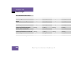
Contents
Transfer case . . . . . . . . . . . . . . . . . . .
Shift ranges . . . . . . . . . . . . . . . . .
Transfer case switch . . . . . . . . . .
Differential locks . . . . . . . . . . . . . . . .
Engaging the differential locks . .
Disengaging the differential
locks . . . . . . . . . . . . . . . . . . . . . .
Good visibility . . . . . . . . . . . . . . . . . .
Headlamp cleaning system . . . . .
Mirrors . . . . . . . . . . . . . . . . . . . . .
Windscreen wipers . . . . . . . . . . .
Windscreen heating . . . . . . . . . . .
Sun visors . . . . . . . . . . . . . . . . . .
Thermatic (automatic air
conditioning) . . . . . . . . . . . . . . . . . . .
Control panel . . . . . . . . . . . . . . . .
Rear air vents . . . . . . . . . . . . . . . .
Switching Thermatic
on and off . . . . . . . . . . . . . . . . . .
Basic settings . . . . . . . . . . . . . . .
Setting the temperature . . . . . . .
Adjusting air distribution
manually . . . . . . . . . . . . . . . . . . .
170
170
170
173
174
175
176
176
176
179
179
181
182
184
184
186
187
187
Adjusting the airflow manually . . .
Defrosting . . . . . . . . . . . . . . . . . .
Air-recirculation mode . . . . . . . . .
Residual heat . . . . . . . . . . . . . . . .
Economy mode . . . . . . . . . . . . . .
Activating/deactivating the
cooling function . . . . . . . . . . . . . .
Rear-compartment air
conditioning . . . . . . . . . . . . . . . . .
Auxiliary heating/ventilation* . . . . .
Before switching on . . . . . . . . . . .
Switching on . . . . . . . . . . . . . . . .
Switching off . . . . . . . . . . . . . . . .
Heater booster system* . . . . . . . . . .
Switch . . . . . . . . . . . . . . . . . . . . .
Water separator* . . . . . . . . . . . . . . .
Open-air . . . . . . . . . . . . . . . . . . . . . . .
Side windows . . . . . . . . . . . . . . . .
Sliding sunroof* . . . . . . . . . . . . . .
Cabriolet soft top . . . . . . . . . . . . .
Draught stop* . . . . . . . . . . . . . . .
Tonneau cover* . . . . . . . . . . . . . .
188
188
189
190
191
191
192
193
193
194
195
196
196
197
198
198
200
201
204
206
Driving systems . . . . . . . . . . . . . . . . .
Cruise control . . . . . . . . . . . . . . .
Variable Speedtronic . . . . . . . . . .
Ultrasound reversing aid* . . . . . .
Features . . . . . . . . . . . . . . . . . . . . . .
Stowage compartments . . . . . . . .
Cup holders . . . . . . . . . . . . . . . . .
Ashtray and cigarette lighter . . . .
Floormats . . . . . . . . . . . . . . . . . . .
Telephone* . . . . . . . . . . . . . . . . .
Mobile phone* version with
code 852 or code 854 (telephone
bracket* with spiral cable) . . . . . .
Mobile phone* version with
code 386 or code 388 (telephone
bracket* without spiral cable) . . .
Mercedes-Benz telematic
services . . . . . . . . . . . . . . . . . . . .
Garage door opener* . . . . . . . . . .
Sockets . . . . . . . . . . . . . . . . . . . .
Steering wheel heating* . . . . . . .
187
Nur fuer internen Gebrauch
208
208
213
218
221
221
224
225
228
228
229
233
236
240
242
243
Contents
Operation . . . . . . . . . . . . . . . . . . . . .
The first 1,500 km . . . . . . . . . . . . . . .
Refuelling . . . . . . . . . . . . . . . . . . . . . .
Petrol (EN 228) . . . . . . . . . . . . . .
Diesel (EN 590) . . . . . . . . . . . . . .
Bleeding the fuel system . . . . . . .
Vegetable oil methyl ester
(V.O.M.E. fuels)* . . . . . . . . . . . . .
Engine compartment . . . . . . . . . . . . .
Bonnet . . . . . . . . . . . . . . . . . . . . .
Engine oil . . . . . . . . . . . . . . . . . . .
Oil level in the automatic
transmission . . . . . . . . . . . . . . . .
Coolant . . . . . . . . . . . . . . . . . . . .
Windscreen washer system,
headlamp cleaning system . . . . .
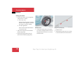
Tyres and wheels . . . . . . . . . . . . . . . .
General notes . . . . . . . . . . . . . . .
Tyre pressures . . . . . . . . . . . . . . .
Interchanging wheels . . . . . . . . . .
245
246
247
248
249
251
251
252
252
254
258
258
259
261
262
263
264
Driving tips . . . . . . . . . . . . . . . . . . . . 265
Driving and parking . . . . . . . . . . . 265
After a cold start . . . . . . . . . . . . . 265
Pulling away on a slippery
surface . . . . . . . . . . . . . . . . . . . . . 265
Free-wheeling with the engine
switched off . . . . . . . . . . . . . . . . . 265
Braking . . . . . . . . . . . . . . . . . . . . . 266
Overrun cut-off . . . . . . . . . . . . . . . 267
Driving in wet conditions . . . . . . . 267
Tyre grip . . . . . . . . . . . . . . . . . . . . 268
Driving in winter . . . . . . . . . . . . . . 268
Off-road driving . . . . . . . . . . . . . . 269
Winter driving . . . . . . . . . . . . . . . . . . 277
Winter tyres . . . . . . . . . . . . . . . . . 277
Snow chains . . . . . . . . . . . . . . . . . 278
Driving abroad . . . . . . . . . . . . . . . . . . 279
Symmetrical dipped-beam
headlamps . . . . . . . . . . . . . . . . . . 279
Trailer towing . . . . . . . . . . . . . . . . . . . 280
Coupling a trailer . . . . . . . . . . . . . 280
Driving with a trailer . . . . . . . . . . . 281
Service . . . . . . . . . . . . . . . . . . . . . . . . 283
Active Service System . . . . . . . . . 283
Clearing the service indicator . . . 284
Missing the service due date . . . . 284
Calling up the service due date . . 285
Resetting the service indicator . . 285
Care . . . . . . . . . . . . . . . . . . . . . . . . . . 286
Caring for the exterior of your
vehicle . . . . . . . . . . . . . . . . . . . . . 287
Practical advice . . . . . . . . . . . . . . . . 291
Troubleshooting . . . . . . . . . . . . . . . . . 292
Automatic transmission . . . . . . . . 296
Soft top switch* . . . . . . . . . . . . . . 297
Keys . . . . . . . . . . . . . . . . . . . . . . . 299
Windscreen wipers . . . . . . . . . . . . 302
Lamps in the switches and
buttons . . . . . . . . . . . . . . . . . . . . . 303
Lamps in the instrument
cluster . . . . . . . . . . . . . . . . . . . . . 307
Display messages . . . . . . . . . . . . . . . 315
Text messages . . . . . . . . . . . . . . . 316
Symbol message . . . . . . . . . . . . . 322
Nur fuer internen Gebrauch
Contents
Where will I find...? . . . . . . . . . . . . . .
Warning triangle, first-aid kit and
vehicle tool kit . . . . . . . . . . . . . . .
Fire extinguisher* . . . . . . . . . . . .
CD changer* . . . . . . . . . . . . . . . .
Spare wheel . . . . . . . . . . . . . . . . .
Opening/closing in an
emergency . . . . . . . . . . . . . . . . . . . .
Unlocking the vehicle . . . . . . . . .
Changing the batteries . . . . . . . .
Fuel filler flap emergency
release . . . . . . . . . . . . . . . . . . . . .
Sliding sunroof* . . . . . . . . . . . . . .
Cabriolet soft top . . . . . . . . . . . . .
Releasing the parking lock
manually . . . . . . . . . . . . . . . . . . .
Changing bulbs . . . . . . . . . . . . . . . . .
Front bulbs . . . . . . . . . . . . . . . . .
Rear bulbs . . . . . . . . . . . . . . . . . .
Before changing bulbs . . . . . . . . .
Changing the front bulbs . . . . . . .
Changing the rear bulbs . . . . . . .
340
340
345
345
346
348
348
349
352
353
354
356
357
357
357
358
358
363
Replacing the wiper blades . . . . . . . .
Removing . . . . . . . . . . . . . . . . . . .
Fitting . . . . . . . . . . . . . . . . . . . . .
Flat tyre . . . . . . . . . . . . . . . . . . . . . . .
Changing a wheel and fitting
the spare wheel . . . . . . . . . . . . . .
Battery . . . . . . . . . . . . . . . . . . . . . . . .
Disconnecting the battery . . . . . .
Removing the battery . . . . . . . . .
Charging and installing the
battery . . . . . . . . . . . . . . . . . . . . .
Connecting the battery . . . . . . . .
Jump-starting . . . . . . . . . . . . . . . . . . .
Jump-starting . . . . . . . . . . . . . . . .
Towing . . . . . . . . . . . . . . . . . . . . . . . .
Front towing eye . . . . . . . . . . . . .
Rear towing eye . . . . . . . . . . . . . .
Towing the vehicle . . . . . . . . . . . .
Transporting the vehicle . . . . . . .
Tow-starting . . . . . . . . . . . . . . . . .
Towing in the event of various
malfunctions . . . . . . . . . . . . . . . .
Fuses . . . . . . . . . . . . . . . . . . . . . . . . .
366
366
366
367
367
372
374
375
375
376
377
377
379
380
380
381
381
381
381
383
Technical data . . . . . . . . . . . . . . . . .
Genuine Mercedes-Benz parts . . . . .
Vehicle electronics . . . . . . . . . . . . . .
Tampering with the engine
electronics . . . . . . . . . . . . . . . . . .
Retrofitting electrical or
electronic equipment . . . . . . . . . .
Vehicle identification plates . . . . . . .
Trailer tow hitch . . . . . . . . . . . . . . . . .
Installation dimensions . . . . . . . .
Engine . . . . . . . . . . . . . . . . . . . . . . . .
Performance . . . . . . . . . . . . . . . . . . .
Speeds . . . . . . . . . . . . . . . . . . . . .
Tyres and wheels . . . . . . . . . . . . . . . .
Speed index for tyres . . . . . . . . . .
Tyres . . . . . . . . . . . . . . . . . . . . . .
Vehicle dimensions . . . . . . . . . . . . . .
Vehicle weights . . . . . . . . . . . . . . . . .
Long-wheelbase station
wagon . . . . . . . . . . . . . . . . . . . . .
Short-wheelbase station
wagon . . . . . . . . . . . . . . . . . . . . .
Cabriolet . . . . . . . . . . . . . . . . . . .
Nur fuer internen Gebrauch
387
388
390
390
390
392
394
394
395
396
396
397
397
398
400
401
401
402
403
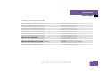
Contents
Trailer loads . . . . . . . . . . . . . . . . . . . .
Service products and capacities . . . .
Fuels . . . . . . . . . . . . . . . . . . . . . .
Engine oil . . . . . . . . . . . . . . . . . . .
Coolant . . . . . . . . . . . . . . . . . . . .
Brake fluid . . . . . . . . . . . . . . . . . .
Windscreen washer system . . . . .
Frequencies for garage door
openers* . . . . . . . . . . . . . . . . . . . . . .
404
405
405
408
409
411
411
Technical terms . . . . . . . . . . . . . . . . 415
Index . . . . . . . . . . . . . . . . . . . . . . . . . 423
412
Nur fuer internen Gebrauch
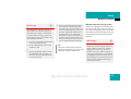
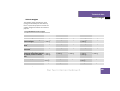
Introduction
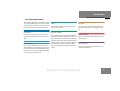
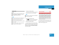
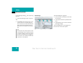
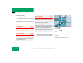
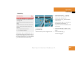
The aim of this manual
The aim of this manual
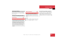
This Owner's Manual is intended to assist
you in all situations with your vehicle. Each
section has its own colour code to help you
find the information you require quickly.
Safety
Operation
This section describes all the safety features of the vehicle.
Here you will find all the information you
will need when you are driving your vehicle.
At a glance
Controls in detail
Here you will find an overview of all the
controls you can operate from the driver's
seat.
This is where you will find more detailed information about the equipment in your vehicle. This section expands on the "Getting
started" section and also describes technical innovations. If you are already familiar
with the basic functions of your vehicle,
you will find this section particularly interesting.
Getting started
Here you will find all the information you
will need when you are driving your vehicle
for the first time. You should read this section first if this is your first Mercedes-Benz
or you have hired the vehicle.
Practical advice
Here you will find practical help for possible problems.
Technical data
All the important technical data for your
vehicle is listed here.
Nur fuer internen Gebrauch
9
Introduction
The aim of this manual
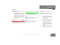
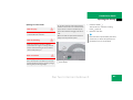
Contents and index
The glossary explains the most important
technical terms.
The table of contents and the index are intended to help you find information quickly.
The following are part of the documentation for your vehicle:
$
This Owner's Manual
$
The brief instructions
$
The "Services" booklet
$
The "Service Centres" booklet
You will receive additional supplementary
instructions, depending on the vehicle's
equipment.
10
Nur fuer internen Gebrauch
Introduction
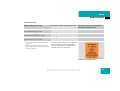
Symbols
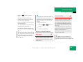
Symbols
You will find the following symbols used in
this Owner's Manual:
*
This asterisk identifies an item of
optional equipment for all models.
The equipment in your vehicle may
differ from some of the descriptions
and illustrations you see here as
not all models have the same standard equipment.
Warning
G
A warning draws your attention to possible
risks to your health or life.
Environmental note
H
An environmental note gives you tips on the
protection of the environment.
!
This symbol means that you have to do
something.
A number of these symbols one after
the other indicates a sequence of actions.
55
A note draws your attention to possible
hazards to your vehicle.
i
A tip contains advice or further information you may find useful.
5
page
This continuation symbol indicates an interrupted sequence
of actions that will be continued
on the next page.
This symbol indicates the page
on which you will find further information on the subject.
->
This symbol in the glossary of
technical terms means that the
term following the arrow is also
explained.
DISPLAY
Messages in the multi-function
display are printed in this font.
Nur fuer internen Gebrauch
11
Introduction
Protection of the environment
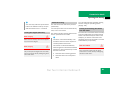
Environmental note
H
DaimlerChrysler's declared policy is one of
integrated environmental protection.
The objectives are for the natural resources
which form the basis of our existence on this
planet to be used sparingly and in a manner
which takes the requirements of both nature
and humanity into account.
You can also contribute to environmental
protection by operating your vehicle in an
environmentally-responsible manner.
Fuel consumption and engine, transmission,
brake and tyre wear depend on the following
two factors:
$
Your vehicle's operating conditions
$
Your style of driving
You can influence both these factors.
Therefore, observe the following points:
Style of driving:
Operating conditions:
$
Do not depress the accelerator pedal
while starting the engine.
$
Avoid driving short distances, as they
increase fuel consumption.
$
$
Make sure that the tyre pressures are
always correct.
Do not warm up the engine with the vehicle stationary.
$
$
Do not carry any unnecessary weight.
$
Keep an eye on the vehicle's fuel consumption.
Anticipate road and traffic conditions
and maintain sufficient distance from
the vehicle in front.
$
Avoid frequent, sudden acceleration.
$
Remove roof racks once you no longer
need them.
$
$
A regularly serviced vehicle contributes
to environmental protection. For this
reason, keep to the service intervals.
Change gear in good time and use each
gear only up to 2/3 of its maximum engine speed.
$
Switch off the engine in stationary
traffic.
$
Always have maintenance work carried
out at a qualified specialist workshop,
e.g. a Mercedes-Benz Service Centre.
Returning used vehicles
If you wish to return your Mercedes-Benz
to have it disposed of in an environmentallyresponsible manner, you can contact
Mercedes-Benz on the following telephone
numbers:
Germany: 00800 1 777 7777
International: +49 69 95 30 72 77
12
Nur fuer internen Gebrauch
Introduction
Operating safety
Operating safety
Risk of accident
G
Work incorrectly carried out on electronic
equipment and its software could stop this
equipment working. The electronic systems
are connected via interfaces. Tampering
with these electronics systems may even
cause malfunctions in systems which have
not been modified.
Such malfunctions could therefore jeopardise the operating safety of your vehicle,
which could put your own safety at considerable risk.
Other work on or modifications to the vehicle carried out incorrectly may jeopardise
the vehicle's operating safety.
Risk of accident
G
Some safety systems only operate when the
engine is running. Therefore, do not switch
off the engine while driving.
Always have service work carried out at a
qualified specialist workshop which has the
necessary specialist knowledge and tools to
carry out the work required. Mercedes-Benz
recommends that you use a Mercedes-Benz
Service Centre for this purpose.
In particular, work relevant to safety or on
safety-related systems must be carried out
at a qualified specialist workshop.
Risk of accident
G
A heavy impact to the underbody, the tyres
or the wheels can lead to damage to your vehicle, for example, when driving the vehicle
off-road or over an obstacle at high speed.
This also applies to vehicles with underbody
protection.
If this occurs, have the vehicle checked at a
qualified specialist workshop which has the
necessary specialist knowledge and tools to
carry out the work required. Mercedes-Benz
recommends that you use a Mercedes-Benz
Service Centre for this purpose.
In particular, work relevant to safety or on
safety-related systems must be carried out
at a qualified specialist workshop.
Nur fuer internen Gebrauch
13
Introduction
Operating safety
Correct use
Observe the following information when
using your vehicle:
$
The safety notes in this manual
$
The "Technical data" section in this
manual
$
National road traffic regulations
$
National road traffic licensing regulations
14
Risk of injury
G
There are various warning stickers affixed to
your vehicle. Their purpose is to make you
and others aware of various risks.
You should not, therefore, remove any of
these warning stickers unless expressly instructed to do so by information on the
sticker itself.
If you remove these warning stickers, you or
others may not then be aware of risks and
may be injured as a result.
Nur fuer internen Gebrauch
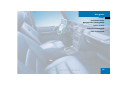
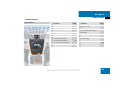
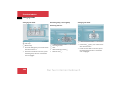
At a glance
Cockpit
Instrument cluster
Multi-function steering wheel
Centre console
Overhead control panel
Door control panel
Nur fuer internen Gebrauch
15
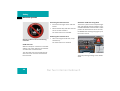
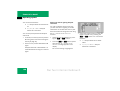
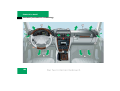
At a glance
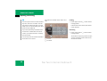
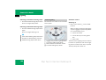
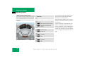
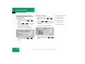
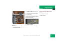
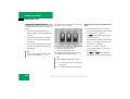
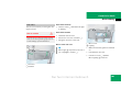
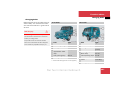
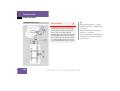
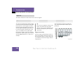
Cockpit
P68.10-2828-31
16
Nur fuer internen Gebrauch
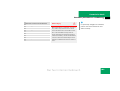
At a glance
Cockpit
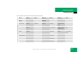
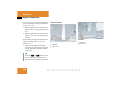
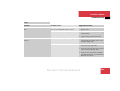
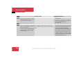
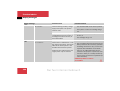
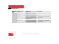
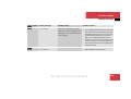
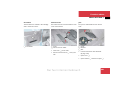
Function
1 Multi-function steering wheel
Page
20,
130
2 Horn
3 Opens the bonnet
4 Adjusts the steering wheel
252
29
5 Adjusts the headlamp range
119
6 Light switch
40,
115
7 Adjusts the exterior mirrors
30
8 Combination switch:
Function
9 Cleans the headlamps
Turn signals
41
$
Windscreen wipers
41
$
Main-beam headlamps
176
a Cruise control lever:
$
Cruise control
208
$
Speedtronic
213
b Instrument cluster
18,
126
c Linguatronic* lever – see separate Operating Instructions
d Ignition lock
e Glove compartment
$
Page
35
221
40,
121
Nur fuer internen Gebrauch
17
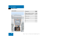
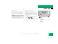
At a glance
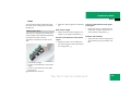
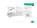
Instrument cluster
P54.30-6734-31
English (miles): P54.30-6735-31
18
Nur fuer internen Gebrauch
At a glance
Instrument cluster
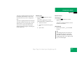
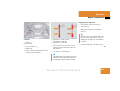
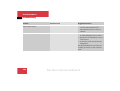
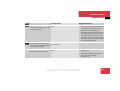
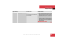
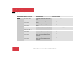
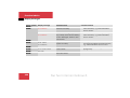
Function
1 Reset button
2 L Turn signal indicator
lamp, left
Page
126
41
Function
4 K Turn signal indicator
lamp, right
Page
Function
41
Automatic transmission selector lever/
shift range
165
313
Malfunction memory
137
143,
134
5 Fuel gauge with:
Reserve fuel warning
lamp
3 Indicator and warning
lamps
Page
v ABS, ESP, 4-ETS warning lamp
307
1 Restraint system warning lamp
312
Outside temperature
or digital road speed
display
? Engine diagnostic indicator lamp (vehicles
with a petrol engine)
314
< Seat belt warning lamp
313
Speedtronic display
336
Clock
142
’ Indicator lamp for
cruise control with
Speedtronic
215
A Main-beam headlamps
indicator lamp
40,
121
q Preglow indicator lamp
(vehicles with a diesel
engine)
38
6 Multi-function display with:
Trip meter
129
7 Speedometer
Total distance
recorder
129
8 Rev counter with:
Transfer case display
171
Nur fuer internen Gebrauch
127
3 Brake system warning
lamp
312
- ABS indicator lamp
309
19
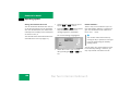
At a glance
Multi-function steering wheel
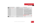
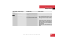
Function
1 Multi-function display
Controlling the operating
system
P46.10-2319-31
2 Selecting a submenu or
adjusting the volume
ç Back/decreases the
volume
æ Forwards/increases
the volume
Page
130
130
Function
4 Jumping from one menu to
another
è Forwards
ÿ Back
5 Scrolling within the menu
j Forwards
k Back
3 Using the telephone*
í Accepts a call
ì Ends a call
20
Nur fuer internen Gebrauch
At a glance
Centre console
Centre console
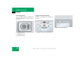
Upper section
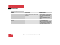
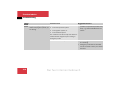
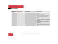
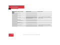
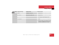
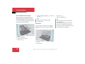
Function
1 Front left seat heating*
94
2 Rear window wiper
43
3 Deactivates ESP
74
Function
8 Switches the hazard warning
lamps on/off
Page
121
174
9 COMAND* or audio system –
see separate Operating Instructions
5 Locks the vehicle centrally
91
a Ashtray with cigarette lighter
226
6 Primes and deactivates
tow-away protection*
77
b Thermatic (automatic air
conditioning)
182
78
c AIRBAG OFF warning lamp
66,
304
4 Engages the differential locks
P68.20-2628-31
Page
Primes and deactivates
the interior motion sensor*
7 Front right seat heating*
94
Nur fuer internen Gebrauch
21
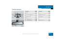
At a glance
Centre console
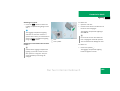
Lower section
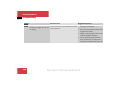
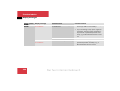
Function
Page
1 Stowage tray
P68.20-2629-31
Water separator* indicator
lamp (not shown here)
197
2 Automatic transmission selector lever
165
3 Auxiliary heating/
ventilation*
193
4 Heater booster system*
196
5 Engages the transfer case
170
6 Parking brake
22
36
Nur fuer internen Gebrauch
At a glance
Overhead control panel
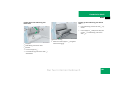
Overhead control panel
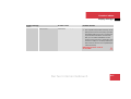
Function
P82.00-2169-31
Page
Function
Page
1 Initiates a TeleAid* emergency call
239
5 Rear-view mirror
30,
179
2 Switches the luggage compartment lighting on/off
124
6 Transmitter buttons for the
garage door opener*
240
3 Switches the right-hand reading lamp on/off
122
7 Indicator lamp for the garage
door opener*
240
8 Controls the interior lighting
122
9 Switches the left-hand reading lamp on/off
122
4 Opens/closes:
$
Sliding sunroof*
200
$
Cabriolet soft top
201
Nur fuer internen Gebrauch
23
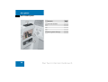
At a glance
Door control panel
Function
1 Opens/closes the front and
rear side windows
P72.10-2593-31
24
Page
198
2 Adjusts the front seat
27
3 Opens door from the inside
85
4 Stores the seat, mirror and
steering wheel settings
102
Nur fuer internen Gebrauch
Getting started
Opening
Adjusting
Driving
Parking and locking
Nur fuer internen Gebrauch
25
Getting started
Opening
The "Getting started" section contains
brief details of the basic functions of the
vehicle. Read this section particularly thoroughly if this is your first Mercedes-Benz
vehicle.
If you are already familiar with the basic
functions described here, the "Controls in
detail" section will help you with more detailed information. The appropriate page
references are at the end of each segment.
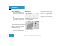
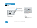
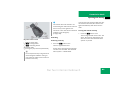
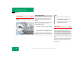
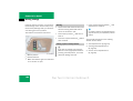
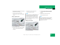
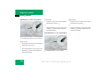
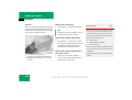
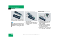
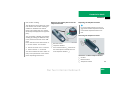
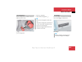
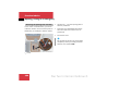
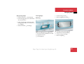
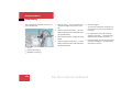
Opening
Press the Πunlocking button on the
key.
The turn signal lamps flash briefly. The
driver's door and fuel filler flap are unlocked.
P80.35-2098-31
Open the door, get into the vehicle and
insert the key in the ignition lock.
You will find further information in the
"Controls in detail" section (5 page 82).
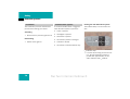
Key with remote control
1 ‹ Locking button
2 ΠUnlocking button
26
Nur fuer internen Gebrauch
Getting started
Adjusting
Adjusting
Seats
Risk of accident
Observe the following points:
G
Only adjust the seats when the vehicle is
stationary. You could otherwise lose control
of the vehicle as a result of an unexpected
seat movement.
Risk of injury
G
Make sure that nobody can be trapped as
the seat is adjusted.
Remove the key from the ignition lock when
leaving the vehicle, even if you are only leaving it for a short time.
$
Position the backrest almost vertically.
$
Your arms should be slightly bent when
you are holding the steering wheel.
$
The distance from the pedals should be
such that you can depress them fully.
The seats can be adjusted when the key is
removed from the ignition lock or a door is
open.
$
The head restraint should support the
back of your head at about eye level.
For this reason, children should never be left
unsupervised in the vehicle.
Failing to observe these notes could result
in injury.
Seat positions which do not allow you to
wear your seat belt correctly are a safety
hazard and must therefore be avoided.
Switch on the ignition. Turn the ignition
55
to position 2 (5 page 35).
Your seat must be adjusted in such a way
that you can wear the seat belt correctly
(5 page 31).
Nur fuer internen Gebrauch
27
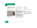
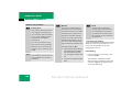
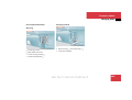
Getting started
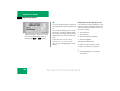
Adjusting
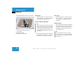
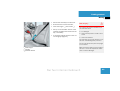
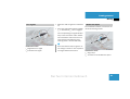
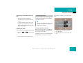
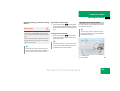
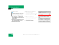
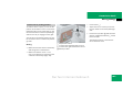
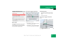
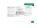
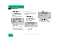
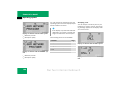
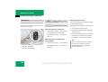
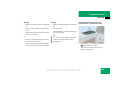
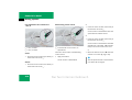
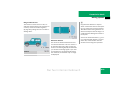
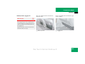
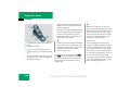
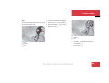
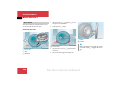
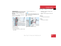
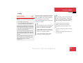
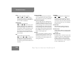
The seat adjustment switch is on the door.
Seat height
P54.25-2768-31
Slide the switch up or down in the direction of arrow 1. Make sure that you
have sufficient head clearance.
28
Slide the switch up or down in the direction of arrow 3 to adjust to a position in which your thighs are lightly
supported.
Seat fore-and-aft adjustment
!
1 Seat height
2 Seat fore-and-aft adjustment
3 Seat angle
4 Backrest angle
5 Head restraint height
Seat angle
When moving the seat, make sure that
there is nothing in the footwell and behind the seats, and that the cup holder* (5 page 224) is folded down. You
could otherwise damage the seat or the
cup holder*.
Slide the switch backwards or forwards
in the direction of arrow 2 until you
can depress the pedals comfortably.
Backrest angle
Slide the switch forwards or backwards
in the direction of arrow 4 to adjust to
a position in which you can hold the
steering wheel comfortably with your
arms slightly bent.
i
You can adjust the seats – with the
front door open – up to approximately
30 minutes after the ignition has been
switched off.
Nur fuer internen Gebrauch
Getting started
Adjusting
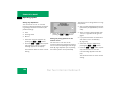
Head restraint height
Slide the switch up or down in the direction of arrow 5.
Head restraint angle
Adjust the angle of the head restraint
by hand. Pull or push.
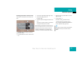
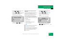
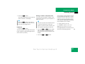
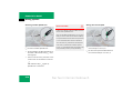
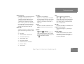
Risk of injury
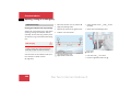
The lever for adjusting the steering wheel
is on the left of the steering column.
Steering wheel
G
Make sure that the back of your head is supported in the middle of the head restraint at
eye level.
This reduces the risk of injury to the head
and neck in the event of an accident or similar situations.
You will find further information about the
seats in the "Controls in detail" section
(5 page 93).
Risk of accident
G
Only adjust the steering wheel when the vehicle is stationary. You could otherwise lose
control of the vehicle as a result of an unexpected steering wheel movement.
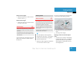
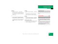
P46.15-2086-31
The steering wheel can be adjusted when
the key is removed from the ignition and a
door is open.
For this reason, children should never be left
unsupervised in the vehicle.
1 Steering column fore-and-aft adjustment
2 Steering column height
i
Steering column fore-and-aft adjust
You can adjust the steering wheel –
with the front door open – up to approx- ment
imately 30 minutes after the ignition
Push the lever forwards or backwards
has been switched off.
in the direction of arrow 1 to adjust to
a position in which you can hold the
Make sure that the ignition is switched
steering wheel comfortably with your
on or the driver's door is open.
arms slightly bent.
Nur fuer internen Gebrauch
29
Getting started
Adjusting
Steering column height
Exterior mirrors
Press the lever up or down in the direction of arrow 2. Make sure that you
can move your legs freely and that you
can see all the displays in the instrument cluster clearly.
i
In vehicles with the memory function
(5 page 102), you can store the steering wheel position together with the position of the seats and the exterior
mirrors.
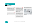
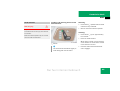
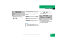
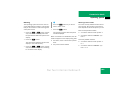
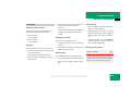
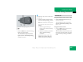
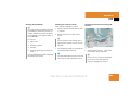
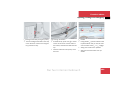
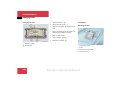
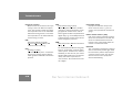
Mirrors
Before starting off, adjust the rear-view
mirror and the exterior mirrors in such a
way that you can get a good overview of
road and traffic conditions.
Rear-view mirror
Adjust the rear-view mirror manually.
30
Risk of accident
G
The exterior mirrors reduce the size of the
image. The objects are actually closer than
they appear.
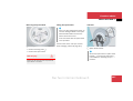
The buttons are located on the left-hand
side of the dashboard.
Make sure that the ignition is switched
on.
Press button 2 for the left-hand exterior mirror or button 3 for the righthand exterior mirror.
Press button 1 at the top or bottom to
the right or left until you have adjusted
the exterior mirrors to the correct position.
You will find further information about adjusting the mirrors in the "Controls in detail" section (5 page 176).
P88.70-2174-31
1 Adjustment button
2 Left-hand exterior mirror
3 Right-hand exterior mirror
Nur fuer internen Gebrauch
Getting started
Driving
Driving
Risk of accident
G
Do not keep any objects in the driver's footwell. If you are using floormats or carpets in
the driver's footwell, make sure that:
$
there is sufficient clearance for the pedals
$
they are safely secured
Objects could otherwise get caught between the pedals if you accelerate or brake
suddenly. You will then not be able to brake,
operate the clutch pedal or accelerate properly. This could lead to accident or injury.
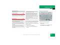
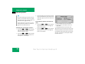
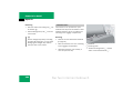
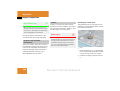
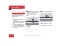
Wearing seat belts
Risk of injury
The lap belt must be routed across your
pelvic area as low down as possible, i.e.
over your hip joints and not across your
stomach or abdomen. If necessary, pull
the belt strap down slightly and retighten in the roll-up direction.
G
If you do not wear your seat belt correctly,
or if you do not engage your seat belt in the
buckle correctly, it cannot perform its intended protective function. Under certain
circumstances, you may even be severely or
fatally injured.
For this reason, make sure that all occupants – in particular, pregnant women –
wear their seat belt correctly at all times
(5 page 31).
$
The seat belt must pass closely over
your body and must not be twisted.
You should therefore avoid wearing
bulky clothing (e.g. winter coats).
$
The shoulder section of the belt must
pass over the middle of your shoulder –
never around your neck or under your
arm – and be pulled so as to fit snugly
against the body.
$
Do not route the belt strap over sharp or
fragile objects, particularly if these are
on or in your clothing, e.g. spectacles,
pens, keys, etc. The belt strap could be
damaged and you could be injured.
$
Only one person may use each seat belt
at any one time. On no account should
children travel sitting on the lap of another occupant as the child cannot be
properly restrained in the event of an accident, sharp braking or sudden change
in direction and the child or other occupants could be seriously or fatally injured.
Nur fuer internen Gebrauch
31
Getting started
Driving
$
Persons less than 1.50 m tall cannot
wear a seat belt correctly. They therefore require special suitable restraint
systems.
Risk of injury
$
Children less than 1.50 m tall and under
twelve years of age cannot wear their
seat belt correctly. Always secure these
children in a suitable child restraint system installed on a suitable seat in the
vehicle (5 page 61). Observe the installation instructions of the child restraint
system manufacturer.
$
Do not secure any objects with a seat
belt if it is also being used by one of the
vehicle's occupants.
32
G
The seat belt can only provide its intended
degree of protection if the backrest is almost vertical and the occupant is therefore
sitting upright. Avoid seat positions that do
not allow the seat belt to be routed correctly
(5 page 31). For this reason, position the
backrest as close to the vertical as possible.
Never drive with the backrest reclined too
far back.
Risk of injury
G
By design, airbags are not activated in all
types of accidents since a correctly fastened seat belt already provides sufficient
protection in many cases. Airbags do not replace seat belts in any way. To reduce the
risk of serious or fatal injury, make sure that
all occupants – in particular, pregnant women – always wear their seat belts correctly,
have adopted a normal sitting position and
that the backrests are almost vertical.
Nur fuer internen Gebrauch
Getting started
Driving
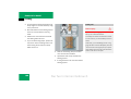
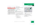
Pull the belt smoothly from belt reel.
Route the belt over the shoulder.
Risk of injury
Click belt tongue 1 into buckle 2.
Pull up on the shoulder section of the
seat belt to tighten the belt across the
lap, if necessary.
You could be injured in an accident if you
use seat belts which:
P91.10-2420-31
If necessary, adjust the belt to the correct height (5 page 34).
G
$
are damaged
$
have been subjected to a load in an accident
$
have been modified
The seat belts will no longer function or provide their intended degree of protection.
Do not route the belt strap over sharp edges
as it could tear.
1 Belt tongue
2 Buckle
3 Release button
Make sure that the seat belt is not caught in
the door or in the seat adjustment mechanism. It could be damaged.
Nur fuer internen Gebrauch
33
Getting started
Driving
Check the seat belts for damage regularly.
You should never modify the seat belts yourself. They might no longer function correctly.
Always have seat belts that are damaged or
have been subjected to a load in an accident
replaced at a qualified specialist workshop,
as it has the necessary specialist knowledge
and tools for the work required.
Mercedes-Benz recommends that you use a
Mercedes-Benz Service Centre for this purpose.
In particular, work relevant to safety or on
safety-related systems must be carried out
at a qualified specialist workshop.
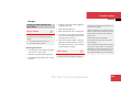
Belt height adjustment
Raising the belt
You can adjust the seat belt height for the
following seats:
$
Driver's seat
$
Front-passenger seat
$
Outer rear seats
Adjust the belt height so that the shoulder
belt is routed over the middle of your
shoulder.
P91.40-2395-31
Push the belt sash guide up.
The belt sash guide engages in five different positions.
Lowering the belt
Press and hold release button 1.
Move the belt sash guide to the required height.
Let go of release button 1 and ensure
that the height adjustment mechanism
is engaged at a detent.
Please observe the information about
the correct way to wear the seat belt
(5 page 31).
1 Release button
34
Nur fuer internen Gebrauch
Getting started
Driving
i
Ignition lock
Risk of injury
Remove the key from the ignition lock when
leaving the vehicle, even if you are only leaving it for a short time.
The seats and the steering wheel can be adjusted when the key is out of the ignition and
the door is open.
For this reason, do not leave children unsupervised in the vehicle, as they could become trapped when the seat or steering
wheel is adjusted.
Risk of accident
The key can only be removed when:
G
G
$
it is turned to position 0 in the ignition lock
$
the selector lever of an automatic
transmission is moved to position P
$
the brake pedal is not depressed.
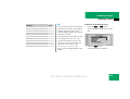
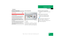
P82.00-2170-31
Ignition lock
0 To remove the key
1 Power supply for some consumers, e.g.
the seat adjustment function
2 Ignition (power supply for all consumers) and drive position
3 To start the engine (5 page 37)
To unlock the steering wheel, turn the
steering wheel slightly as you turn the
key to position 1.
Only remove the key from the ignition lock
when the vehicle is stationary.
You cannot steer the vehicle with the key removed.
Nur fuer internen Gebrauch
35
Getting started
Driving
You will find further information about the
automatic transmission in the "Controls in
detail" section (5 page 81).
Automatic transmission
Parking brake
Risk of accident
G
Never leave children unsupervised in the vehicle, as they could release the parking
brake. This could lead to an accident and
could cause injury or fatalities.
Applying the parking brake
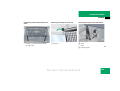
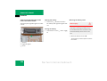
P27.00-2107-31
P42.20-2116-31
Pull lever 1 firmly upwards.
The 3 brake system warning lamp
in the instrument cluster lights up if the
ignition is switched on.
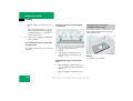
Parking brake
Automatic transmission gearshift pattern
P
R
N
D
Park position with selector lever lock
Reverse gear
Neutral
Driving position
36
1 Lever
2 Release knob
Nur fuer internen Gebrauch
Getting started
Driving
Releasing the parking brake
i
Starting the engine
Pull lever 1 upwards slightly, press release knob 2 and guide lever 1 down
fully.
The vehicle can move immediately.
The 3 brake system warning lamp
in the instrument cluster goes out.
i
A warning signal sounds if you pull away
with the parking brake applied.
Risk of poisoning
G
Never run the engine in enclosed spaces.
Exhaust fumes contain poisonous carbon
monoxide. Inhaling exhaust fumes constitutes a health hazard. It can lead to loss of
consciousness and death.
If you depress the brake while you are
starting the engine, the pedal travel will
be longer than usual and the pedal resistance low.
If you depress the brake after starting
the engine, the pedal travel and resistance return to normal.
!
Do not depress the accelerator pedal
during the starting procedure.
Nur fuer internen Gebrauch
37
Getting started
Driving
Starting the diesel engine
Starting the petrol engine
Apply the parking brake.
Apply the parking brake.
Shift the selector lever to P or N.
Shift the selector lever to P or N.
!
!
Do not depress the accelerator pedal
during the starting procedure.
Do not depress the accelerator pedal
during the starting procedure.
Turn the ignition to position 3 in the ignition lock (5 page 35) and release the
key.
The engine starts automatically.
Turn the ignition to position 2
(5 page 35).
The q preglow indicator lamp lights
up in the instrument cluster.
As soon as the q preglow indicator
lamp has gone out, turn the key to position 3 and release it.
The engine starts automatically. If after
a given time the engine has not started,
the starting procedure is terminated
automatically. You can terminate the
starting procedure manually at any
time.
Turn the key to position 0 in the ignition
lock.
The starting procedure is terminated.
i
If the engine is warm, you can start it
without preglow.
38
Nur fuer internen Gebrauch
Getting started
Driving
Pulling away
!
Only select reverse gear when the vehicle is stationary. Otherwise, you will
damage the transmission.
You can open the doors from the inside
at any time.
You can also switch off the automatic
locking function (5 page 91).
Risk of accident
Shift the selector lever to D or R.
Do not shift down until the road speed is in
the permissible range for the gear required.
Wait for the shift process to complete
before pulling away.
G
The selector lever lock will be released.
i
i
The vehicle will lock itself centrally once
you have pulled away. The locking
knobs in the doors drop down.
Depress the brake pedal.
Release the parking brake.
The 3 brake system warning lamp
in the instrument cluster goes out.
Release the brake pedal.
Gently depress the accelerator pedal.
Do not shift down for additional engine braking on a slippery surface. The drive wheels
could lose their grip and the vehicle could
skid. You could lose control of your vehicle
and cause an accident.
You will find further information about the
automatic transmission in the "Controls in
detail" section (5 page 164).
Upshifts are made at higher engine speeds
after a cold start. This helps the catalytic
converter to reach its operating temperature more quickly.
Nur fuer internen Gebrauch
39
Getting started
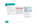
Driving
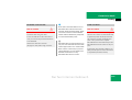
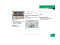
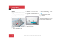
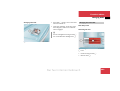
Switching on the headlamps
Dipped-beam headlamps
The switch is located between the steering
wheel and the driver's door.
Make sure that the ignition is switched
on.
Turn the light switch to B. The
headlamps are switched on.
Main-beam headlamps
i
P54.25-2771-31
On some country-specific vehicle models, the dipped-beam headlamps come
on when you switch on the ignition.
P54.25-2770-31
Combination switch
1 Main-beam headlamps
2 Headlamp flasher
Light switch
1 Headlamps off
2 Dipped-beam headlamps on
Press the combination switch forwards
to 1.
The main-beam headlamps are
switched on.
The A indicator lamp in the instrument cluster lights up.
40
Nur fuer internen Gebrauch
Getting started
Driving
Turn signals
P54.25-2844-31
Make sure that the ignition is switched
on.
Press the combination switch upwards
1 or downwards 2 until it engages.
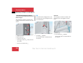
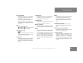
Windscreen wipers
The combination switch is located on the
left of the steering column.
The corresponding turn signal indicator
lamp in the instrument cluster flashes.
The combination switch returns to its
initial position automatically if the
steering wheel is turned sufficiently.
Combination switch
1 Right-hand turn signal
2 Left-hand turn signal
P54.25-2845-31
i
Press the switch briefly to signal a minor change in direction. The respective
turn signal flashes three times.
Combination switch
1 Single wipe
2 To switch on the windscreen wipers
Nur fuer internen Gebrauch
41
Getting started
Driving
Switching on the windscreen wipers
Make sure that the ignition is switched
on.
Turn the combination switch to the correct setting depending on the intensity
of the rain.
0 Windscreen wipers off
I
Intermittent wipe (interval depends
on how heavy the rain is)
II Normal wipe
III Rapid wipe (reverts to normal wipe
with the vehicle stationary)
42
i
Single wipe
If the vehicle is stationary, the windscreen wipers automatically return to
intermittent wipe.
If you open a door, the intermittent
wipe stops. This protects people entering and leaving the vehicle from being
splashed. Intermittent wipe continues
when you:
$
close the doors again
$
turn the combination switch to position II or III
$
move the selector lever to D or R
Briefly press the switch to the pressure
point in the direction of arrow 1.
The windscreen wipers wipe once without windscreen washer fluid.
Wiping using windscreen washer fluid
Press the switch beyond the pressure
point in the direction of arrow 1.
The windscreen wiper wipes with washer fluid while the switch is being
pressed.
Nur fuer internen Gebrauch
Getting started
Driving
i
Rear window wiper
Switching on intermittent wipe
You should also use washer fluid when
wiping the windscreen in the rain. This
prevents smears on the windscreen.
The switch is located on the upper section
of the centre console.
Make sure that the ignition is switched
on.
Press upper section 1 of the switch.
Indicator lamp 2 lights up.
i
You can use position I as a universal
setting. The correct wiping frequency is
selected according to the intensity of
the rain.
You will find further information about the
combination switch in the "Controls in detail" section (5 page 121).
Switching off intermittent wipe
P54.25-2772-31
Press upper section 1 of the switch
again.
Indicator lamp 2 goes out.
1 Intermittent wipe
2 Indicator lamp
3 Windscreen washer system
Wiping using windscreen washer fluid
When you release the switch, the rear
window will continue to be wiped for
about another five seconds.
i
The rear window wiper comes on automatically if the windscreen wipers are
switched on and you engage reverse
gear.
Press and hold lower section 3 of the
switch.
You will find further information about the
windscreen wipers in the "Controls in detail" section (5 page 179).
Nur fuer internen Gebrauch
43
Getting started
Parking and locking
You have now completed your first journey. You have stopped your vehicle and
have parked properly. End your journey as
follows:
Risk of accident
G
Only remove the key from the ignition lock
when the vehicle is stationary. You cannot
steer the vehicle with the key removed.
Make sure that the transfer case is not in position N.
Never leave children unsupervised in the vehicle. They could release the parking brake.
This could lead to an accident and could
cause injury or fatalities.
44
Apply the parking brake (5 page 36).
Move the selector lever to P.
Turn the key to position 0 in the ignition
lock (5 page 35) and remove it.
The immobiliser is activated.
!
Whenever you stop the vehicle, always
remove the key to prevent the battery
from discharging.
i
On steep slopes, turn the front wheels
towards the kerb.
Turn the steering wheel until the steering wheel lock engages.
Press the release button on the seat
belt (5 page 33).
Risk of injury
G
Make sure that nobody can be trapped as
you close the doors.
Press the ‹ locking button on the
key (5 page 26).
The turn signal lamps flash briefly three
times. The locking knobs in the doors
drop down. The vehicle is locked.
You will find further information about
locking the vehicle in the "Controls in detail" section (5 page 82).
Nur fuer internen Gebrauch
Safety
Restraint systems
Driving safety systems
Anti-theft systems
Nur fuer internen Gebrauch
45
Safety
Restraint systems
This section will familiarise you with the
most important features of the restraint
systems in your vehicle. In the event of an
accident, your vehicle may collide with another object, e.g. another vehicle. This may
result in rapid acceleration or deceleration
of your vehicle. During this acceleration or
deceleration, the vehicle occupants will be
moved towards the force acting on the vehicle. There is therefore the risk of vehicle
occupants injuring themselves on the vehicle interior or on parts of the vehicle. The
purpose of supplemental restraint systems
is to minimise this risk of injury. However,
seat belts and airbags are generally unable
to prevent injuries caused by objects penetrating the vehicle from the outside.
46
The most important restraint systems are:
G
$
Seat belts
Risk of injury
$
Restraint systems for children in the
vehicle
An airbag increases the degree of protection
for vehicle occupants wearing a seat belt
and therefore supplements the seat belt.
Airbags in no way replace the requirement
for all vehicle occupants to wear their seat
belt correctly at all times. This is because,
on the one hand, an airbag is not deployed
in all types of accident, as in some situations
it would not provide any additional protection to that already provided by a correctly
fastened seat belt.
If necessary, the following also provide additional protection:
$
$
SRS system (Supplemental Restraint
System) consisting of:
$
Belt tensioners
$
Belt force limiters
$
Airbags
Roll-over bar
Nur fuer internen Gebrauch
Safety
Restraint systems
On the other hand, airbag deployment only
provides increased protection if the seat
belt is worn correctly because:
$
the belt helps to hold the vehicle occupant in the best position in relation to
the airbag
$
it can significantly reduce the movement of the vehicle occupant towards
the force of the impact, e.g. in the event
of a head-on collision, and therefore reduce the risk of injury
Risk of injury
G
In accidents in which an airbag is activated,
the airbag can only provide additional protection to that already provided by the seat
belt if the seat belt is worn correctly.
Seat belts
The most important restraint systems are
the seat belts and restraint systems for
children in the vehicle. In the event of a
collision, these reduce the movement of
the vehicle occupants in the direction of
the impact and therefore reduce the risk
of them hitting parts of the vehicle interior.
For this reason, make sure that all vehicle
occupants – in particular, pregnant women
– wear their seat belt correctly at all times.
Only then can all the restraint systems provide the best possible protection.
Make sure that the belt:
$
is routed across your pelvis as low down
as possible, i. e. across your hip joints
and not across your abdomen
$
fits closely
$
is not twisted
G
$
is routed across the middle of your
shoulder
If you do not wear your seat belt correctly,
or if you do not engage your seat belt in the
buckle correctly, it cannot perform its intended protective function. Under certain
circumstances, you may even be severely or
fatally injured.
$
is not routed across your neck or under
your arm
$
is pulled tight across the hip joints by
pulling the shoulder section of the belt
up
In many countries, there are regulations
concerning the use of seat belts and child
restraint systems.
Risk of injury
Nur fuer internen Gebrauch
47
Safety
Restraint systems
Only one person may use each seat belt at
any one time.
Never use a seat belt to secure objects if it
is already being used by one of the vehicle
occupants.
Avoid wearing bulky clothing, e.g. winter
coats.
Do not route the belt strap over sharp or
fragile objects, particularly if these are on
or in your clothing, e.g. spectacles, pens
or keys. The belt strap could tear and you or
other vehicle occupants could be injured.
48
On no account should children travel sitting
on the lap of another occupant. The child
cannot then be properly restrained in the
event of an accident, sharp braking or sudden change in direction and the child or the
other vehicle occupants could be seriously
or fatally injured.
Persons less than 1.50 m tall or children
under twelve years of age cannot wear their
seat belt properly. They therefore require
additional restraint systems fitted on suitable seats in the vehicle for protection in the
event of an accident. Always follow the child
restraint system manufacturer's installation
instructions.
Risk of injury
G
The seat belt can only provide its intended
degree of protection if the backrest is positioned almost vertically and the occupant
is therefore sitting upright. Avoid seat positions that do not allow the seat belt to be
routed correctly. For this reason, position
the backrest as close to the vertical as possible. Never drive with the backrest reclined
too far back.
Nur fuer internen Gebrauch
Safety
Restraint systems
Risk of injury
G
The seat belt cannot function correctly if the
belt strap or the belt buckle is dirty or damaged. You must therefore keep the belt
strap and buckle clean, otherwise the belt
tongue cannot engage correctly.
Regularly check that the seat belts:
$
are not damaged
$
are not routed over sharp edges
$
are not twisted
Have seat belts which have been damaged
or subjected to heavy loads in an accident
replaced. Their anchorages should also be
checked.
Mercedes-Benz recommends that, for safety
reasons, you only use seat belts that have
been specially approved for your vehicle by
Mercedes-Benz.
Risk of injury
The belt strap could otherwise tear and you
or others could be injured.
G
Modifications to or work incorrectly carried
out on a restraint system (seat belts and
their anchorages, belt tensioners, belt force
limiters or airbags) or its wiring could prevent the restraint system from functioning
correctly.
The airbags or belt tensioners could, for example, be activated inadvertently or could
fail in accidents in which the deceleration
force is sufficient to trigger the airbag. For
this reason, you should never modify the restraint systems.
Risk of injury
G
By design, airbags are not activated in all
types of accidents since a correctly fastened seat belt already provides sufficient
protection in many cases. Airbags do not replace seat belts in any way. To reduce the
risk of serious or fatal injury, make sure that
all vehicle occupants – in particular, pregnant women – always have their seat belt
fastened correctly, have adopted a normal
sitting position and that the backrests are
almost vertical.
Nur fuer internen Gebrauch
49
Safety
Restraint systems
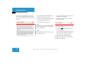
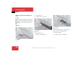
Fastening a lap-shoulder seat belt
P91.10-2420-31
Pull the belt smoothly from belt reel.
Route the belt over the shoulder.
Engage belt tongue 1 in buckle 2.
Pull up on the shoulder section of the
seat belt to tighten the belt across the
lap if necessary.
If necessary, adjust the belt to the correct height (5 page 34).
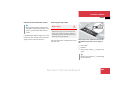
Fastening the rear centre lap-shoulder
seat belt
P91.14-2002-31
Releasing the lap-shoulder seat belt
1 Belt tongue
2 Buckle
3 Release button
50
Press release button 3 on belt buckle
2.
1 Belt tongue retainer
2 Buckle for fixed belt tongue
3 Release button for fixed belt tongue
4 Fixed belt tongue
5 Buckle for free belt tongue
6 Release button for free belt tongue
7 Free belt tongue
Nur fuer internen Gebrauch
Safety
Restraint systems
Releasing the rear centre lap-shoulder
seat belt
Pull the belt tongues out of retainer 1.
Pull the belt smoothly from the belt
reel.
Click fixed belt tongue 4 into buckle
2.
Press release button 6 on belt buckle
5.
Press release button 3 on belt buckle
2.
Route the belt over the body using free
belt tongue 7.
Click the free belt tongue into buckle
5.
Pull up on the shoulder section of the
seat belt to tighten the belt across the
lap if necessary.
Stowing the rear centre lap-shoulder
seat belt
Let the belt roll up to the stop.
Guide both belt tongues into retainer
1 on top of each other.
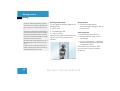
SRS
The SRS system (Supplemental Restraint
System) consists of:
$
Restraint system warning lamp
$
Belt tensioners
$
Belt force limiters
$
Airbag system
Nur fuer internen Gebrauch
with:
$
Airbag control unit
$
Airbag
51
Safety
Restraint systems
Restraint system warning lamp
The 1 restraint system warning lamp in
the instrument cluster lights up:
$
for approximately four seconds when
you turn the ignition to position 1
This indicates that the restraint systems are operational.
$
continuously when you turn the ignition
to position 2
This indicates that the 1 restraint
system warning lamp is operational.
The SRS system performs regular selfchecks while the engine is running. This
means that faults can be detected in good
time.
52
Risk of injury
G
There is a fault if the 1 restraint system
warning lamp does not light up when you
switch on the ignition, does not go out a few
seconds after the engine is running or lights
up again. Some systems may be activated
inadvertently or not at all in the event of a
collision. If this occurs, have the SRS system
checked and repaired immediately at a qualified specialist workshop which has the necessary specialist knowledge and tools to
carry out the work required. Mercedes-Benz
recommends that you use a Mercedes-Benz
Service Centre for this purpose.
Activation of the belt tensioners, belt
force limiters and airbags
In the event of a collision, the sensor in
the airbag control unit evaluates important
physical data, such as duration, direction
and degree of vehicle deceleration or acceleration. Based on the evaluation of this
data and depending on the vehicle's rate of
longitudinal deceleration in a collision, the
belt tensioners are the first to be triggered
by the airbag control unit. The front airbags
are not triggered until a second activation
threshold is reached, i.e. an even higher
rate of vehicle deceleration in the longitudinal direction is exceeded.
In particular, work relevant to safety or on
safety-related systems must be carried out
at a qualified specialist workshop.
Nur fuer internen Gebrauch
Safety
Restraint systems
i
Airbag deployment depends on various
factors, such as:
The belt tensioners and airbags are only
triggered if the seat belt is fastened. On $ the initial rate of deceleration or acceleration
the front-passenger side, the airbag is
only triggered if the front-passenger
$ the duration and direction of the decelseat occupation recognition system deeration or acceleration
tects that the front-passenger seat is
occupied or the seat belt tongue is en- $ the distribution of the force during a
collision
gaged in the buckle.
$ the collision angle
The activation thresholds for the belt ten$ the deformation characteristics of the
sioners and airbags are variable and are
vehicle
adapted to the rate of vehicle deceleration.
This process is pre-emptive in nature as
$ the characteristics of the object with
airbag deployment must take place during
which the vehicle collides, e.g. the oththe collision and not after it has happened.
er vehicle
Factors which can only be seen and measured after the collision has taken place
cannot be taken into account when triggering the airbag and are not decisive for this.
If necessary, they can be used to help reconstruct the sequence of events in an accident. These factors include:
$
the speed of the vehicle at the time of
the collision
$
injuries to the vehicle occupants
$
vehicle deformation
The vehicle may be considerably deformed
without an airbag being triggered, e.g. if
only relatively easily-deformable vehicle
parts are affected by the collision and the
required deceleration threshold is not
reached. On the other hand, airbags may
be triggered even though the vehicle only
displays minor deformation, if, for example, rigid vehicle parts such as a longitudinal member are affected by the collision
thus causing vehicle deceleration to
exceed the pre-determined threshold.
Nur fuer internen Gebrauch
53
Safety
Restraint systems
Risk of injury
G
Airbags are not triggered in all types of accident. They are controlled by complex sensor
technology and evaluation logic. This process is pre-emptive in nature as airbag deployment must take place during the impact
and must be adapted to provide calculated,
additional protection for the vehicle occupants. Not all airbags must be triggered in
the event of an accident.
The different airbag systems operate independently of each other. However, each system is dependent on the type of accident
(head-on, side, rear-end impact or overturning) and severity of the accident (mainly
vehicle deceleration or acceleration) determined during the initial phase of the
accident.
54
Belt tensioners and belt force limiters
i
The front seat belts and the outer rear seat
belts are fitted with belt tensioners and
belt force limiters.
Belt tensioners do not correct:
!
Do not place any heavy objects on the
front-passenger seat and do not insert
the belt tongue on the front passenger
seat belt into the buckle if the frontpassenger seat is not occupied.
The belt tensioner and the airbags on
the front-passenger side could otherwise be triggered in the event of an accident.
In the event of a collision, the belt tensioners tighten the seat belts, pulling them
close against the body.
$
incorrect sitting positions
$
incorrectly worn seat belts
Belt tensioners do not pull occupants
back towards the seat backrest.
Triggered belt force limiters reduce the
load exerted by the seat belt on the occupants.
When the ignition is switched on, the belt
tensioners and belt force limiters function:
$
if the restraint systems are operational
(the 1 restraint system warning
lamp lights up after the ignition is
switched on) (5 page 35).
Nur fuer internen Gebrauch
Safety
Restraint systems
$
$
$
for the driver's and front-passenger
lap-shoulder seat belts and for the left
and right lap-shoulder seat belts in the
rear if they are engaged in the belt
buckle
in the event of a head-on or rear-end
collision, if the vehicle has a high rate
of acceleration or deceleration in a longitudinal direction in the initial stages
of the collision
on the front-passenger side, if the
front-passenger seat is occupied in vehicles on vehicles with front-passenger
seat occupancy recognition*
If the belt tensioners are triggered, you will
hear a bang, which is not hazardous to your
hearing, and some dust may be released.
The 1 restraint system warning lamp
lights up.
i
An indication that a belt tensioner in the
rear has been triggered is that the buckle is pulled down and is almost flush
with the top of the seat.
Risk of injury
G
The rear belt tensioners only function if they
can pull the belt buckles down without hindrance.
This action must not be impeded in any way,
therefore:
Do not grasp the buckles
Do not place any objects underneath the
buckles
Risk of injury
G
If the belt tensioners have been triggered,
have them replaced at a qualified specialist
workshop which has the necessary specialist knowledge and tools to carry out the
work required. Mercedes-Benz recommends
that you use a Mercedes-Benz Service Centre for this purpose.
In particular, work relevant to safety or on
safety-related systems must be carried out
at a qualified specialist workshop.
Observe the safety regulations when disposing of belt tensioners. Any Mercedes-Benz
Service Centre can provide details of these
regulations.
This could otherwise adversely affect operation of the belt tensioner or render it completely ineffective. You would then have no
additional protection.
Nur fuer internen Gebrauch
55
Safety
Restraint systems
Airbag system
G
$
Do not lean on the doors from inside the
vehicle.
Airbags offer an additional degree of protection, but do not replace the seat belts in any
way. You are therefore only sufficiently protected if you wear your seat belt correctly at
all times.
$
Do not put your feet on the dashboard.
$
Only hold the steering wheel by the rim.
This allows the airbag to inflate fully. If
you hold the steering wheel by the inside, you could be injured if the airbag is
triggered.
$
Do not place any objects on the airbags
or between the airbags and the vehicle's
occupants.
$
Do not hang any hard objects, such as
coat hangers, on the grab handles.
$
Do not place any objects between the
backrest and the door.
Risk of injury
Risk of injury
G
The service life of the front-passenger airbag
is limited to 15 years. Have the frontpassenger airbag replaced after no more
than 15 years at a qualified specialist
workshop which has the necessary specialist knowledge and tools to carry out the
work required. Mercedes-Benz recommends
that you use a Mercedes-Benz Service Centre for this purpose.
In particular, work relevant to safety or on
safety-related systems must be carried out
at a qualified specialist workshop.
To reduce the risk of serious or fatal injury
by an airbag inflating in an accident, please
observe the following points:
$
All vehicle occupants – in particular,
pregnant women – must wear their seat
belt correctly at all times.
$
Choose a seat position as far back from
the airbag as possible and which still allows you to drive the vehicle safely.
$
56
Do not lean forwards while the vehicle is
in motion, e.g. over the padded boss of
the steering wheel.
The risk of skin abrasions or minor injuries
caused by an airbag cannot be completely
ruled out due to the high speed at which the
airbag is required to inflate.
Nur fuer internen Gebrauch
Safety
Restraint systems
Risk of injury
G
Correct operation of the airbags can only be
guaranteed if:
$
you do not place any objects under the
seat cushion of the front-passenger seat
$
you do not cover the padded boss of the
steering wheel, the front-passenger airbag cover or the areas of the roof lining
accommodating the windowbags, and
you do not stick any badges or stickers
on them
$
you do not carry out any modifications
to the restraint systems, including their
wiring
Risk of injury
G
To reduce the risk of serious or fatal injury in
the event of an accident with a high rate of
deceleration, e.g. due to an airbag inflating
within milliseconds, or in the event of sudden braking, please observe the following:
$
All vehicle occupants must select a seat
position in which they can wear their
seat belt correctly and which is as far
back from the airbag as possible. The
driver's seat position must allow him to
drive the vehicle safely. The driver's
arms should be slightly bent when holding the steering wheel. The driver must
maintain the correct distance from the
pedals such that he or she can depress
them fully.
$
Position the front-passenger seat as far
back as possible, particularly if a child is
sitting on this seat or is secured in a
child restraint system on this seat.
$
Vehicle occupants must wear their seat
belt correctly at all times and sit back
against the backrest which should be almost vertical. The head restraint should
support the back of your head at about
eye level.
$
Rearward-facing child seats must not be
secured on the front-passenger seat if
the front-passenger front airbag is not
deactivated or cannot be deactivated. In
Mercedes-Benz vehicles with automatic
child seat recognition, the front-passenger airbag is deactivated if a child restraint system with automatic child seat
recognition is fitted to the front-passenger seat and the AIRBAG OFF warning
lamp is lit.
If your vehicle does not have automatic
child seat recognition, children must be
secured in a child restraint system on a
suitable seat in the rear.
If you fit a forward-facing child seat on
the front-passenger seat, you must
move the front-passenger seat to its
rearmost position.
Nur fuer internen Gebrauch
57
Safety
Restraint systems
If you sell your vehicle, you are obliged to
make the buyer aware of these points. You
should therefore pass on this Owner's Manual to the new owner for this purpose.
Observe the safety regulations when disposing of airbag units. Any Mercedes-Benz Service Centre can provide details of these
regulations.
Your vehicle is fitted with the following airbags:
Airbag deployment
The airbag inflates within milliseconds. The
1 restraint system warning lamp lights
up.
i
If the airbags are triggered, you will hear
a bang and some dust may be released.
This bang is not harmful to your hearing
and the dust does not constitute a
health hazard.
$
Driver's front airbag, located in the
steering wheel
The inflated airbag slows and restricts
movement of the vehicle occupants.
$
Front-passenger front airbag above the
glove compartment
$
Windowbags above the side windows
If a vehicle occupant makes contact with
an airbag which has been deployed, the
airbag will release some hot gas. This feature is designed to reduce the force acting
on the occupant's head and chest. The airbag is therefore depressurised after the
accident.
58
Risk of injury
G
After the airbags have been triggered:
$
Airbag parts are hot. Do not touch them
as you could burn yourself
$
You must have the airbags replaced at a
qualified specialist workshop which has
the necessary specialist knowledge and
tools to carry out the work required.
Mercedes-Benz recommends that you
use a Mercedes-Benz Service Centre for
this purpose. In particular, work relevant
to safety or on safety-related systems
must be carried out at a qualified specialist workshop
Nur fuer internen Gebrauch
Safety
Restraint systems
Risk of injury
G
When an airbag inflates, a small amount of
fine powder is released. This powder does
not constitute a health hazard and does not
indicate that there is a fire in the vehicle.
The powder could cause short-term breathing difficulties for persons suffering from
asthma or other respiratory conditions. To
prevent these breathing difficulties, you
should either leave the vehicle as soon as it
is safe to do so or open the windows to let
fresh air in.
Front airbags
The front airbags are designed to increase
protection to the head and chest of the
driver and front passenger. The driver's
front airbag and the front-passenger front
airbag are triggered:
$
The driver's front airbag is located in the
steering wheel; the front-passenger front
airbag is located above the glove compartment.
in the initial stages of an accident with
a high rate of acceleration or deceleration acting on the front of the vehicle
$
if it is predicted that additional protection would be provided
$
if the seat belt is fastened
$
if the vehicle overturns, never, unless
the system detects high vehicle deceleration in a longitudinal direction
P54.30-2471-31
1 Driver's airbag
2 Front-passenger airbag
The driver's front airbag inflates in front of
the steering wheel; the front-passenger
front airbag inflates in front of and above
the glove compartment.
Nur fuer internen Gebrauch
59
Safety
Restraint systems
Front-passenger airbag 2 will only be triggered if:
$
Windowbags
$
in the event of a side impact on the side
of the impact
$
if the impact exceeds a predetermined
force
$
independently of the driver's and frontpassenger airbags
the front-passenger seat is occupied
and
$
The windowbags are triggered:
the AIRBAG OFF warning lamp on the
centre console is not lit (5 page 21).
This means that a child seat with automatic child seat recognition has not
been fitted or has been incorrectly fitted
P91.60-2772-31
The windowbags will not be triggered in
the event of a minor side impact.
1 Windowbags (arrows)
!
Do not place any heavy objects on the
front-passenger seat. The belt tensioner and the airbags on the front-passenger side could otherwise be triggered
in the event of an accident and would
then have to be replaced.
60
Nur fuer internen Gebrauch
Safety
Restraint systems
Children in the vehicle
If children are travelling in the vehicle:
$
$
secure each child using a child restraint system which is appropriate to
his/her age and size, and which has
been approved for Mercedes-Benz vehicles, preferably on a suitable rear
seat
Risk of injury
Do not leave children unsupervised in the
vehicle, even if they are secured in a child
restraint system. The children could:
$
injure themselves on parts of the vehicle
$
press the central locking button, thereby releasing the child-proof locks, and
then open the doors. They could injure
themselves or others, or they could get
out of the vehicle and injure themselves
or be injured by passing vehicles
make sure that the children are
strapped in throughout the journey
You can obtain child seats and information
about the correct child restraint system
from any Mercedes-Benz Service Centre.
G
$
Child restraint systems
Mercedes-Benz recommends that you only
use the child restraint systems listed on
(5 page 63).
Risk of injury
G
To reduce the risk of serious or fatal injuries
to children in the event of an accident, sharp
braking or sudden change in direction:
$
be seriously or fatally injured due to long
periods of exposure to high temperatures
Nur fuer internen Gebrauch
always secure children less than 1.50 m
tall or under twelve years of age in a special child restraint system fitted on a
suitable seat in the vehicle, as they cannot wear the seat belts properly
61
Safety
Restraint systems
$
do not secure children under twelve
years old on the front-passenger seat
unless the child is secured in a child restraint system with automatic child seat
recognition or a forward-facing child
seat and the front-passenger seat is in
its rearmost position
$
children must never travel sitting on the
lap of another occupant. Children cannot be restrained in the event of an accident, sharp braking or sudden change of
direction due to the forces which act.
They would be thrown against parts of
the vehicle interior and could be seriously or fatally injured
$
all vehicle occupants must wear their
seat belt correctly at all times
62
Risk of injury
G
Follow the manufacturer's installation instructions when fitting a child restraint system.
It is advisable to fit the child restraint system to one of the rear seats. The child is
generally better protected there.
Nur fuer internen Gebrauch
Safety
Restraint systems
Suitable child seats
Weight categories and ages
Child seat on the front-passenger seat
Child seat on the left and right-hand
seat of the rear bench seat
Group 0: up to 10 kg
up to approximately 9 months
As recommended1
Universal
Group I: 9 to 18 kg
approximately 8 months to 4 years
Universal2
Universal
Group II/III: 15 to 36 kg
approximately 3½ to 12 years
Universal2
Universal
1 Only use child seats with automatic child seat
recognition.
2 Move the front-passenger seat to its rearmost
position when using child seats without automatic
child seat recognition.
"Universal" child seats can be recognised
by their orange-coloured approval label.
The label is affixed to the child seat and
identifies the type of child seat.
P91.00-2139-31
aus Ba. 209
Example of a child seat label
Nur fuer internen Gebrauch
63
Safety
Restraint systems
Recommended child restraint systems
Weight categories and ages Manufacturer Type
Approval
number
DaimlerChrysler
order number
Automatic child seat
recognition
Group 0: up to 10 kg
Britax-Römer
up to approximately 9 months
Baby Safe
E1 03 301063
B6 6 86 8169
Yes
Group I: 9 to 18 kg
approximately 8 months to
4 years
Prince
E1 03 301095
B6 6 86 8167
No1
B6 6 86 8168
Yes
Britax-Römer
Britax-Römer
Duo
E1 03 301133
B6 6 86 8205
Yes
Group II/III: 15 to 36 kg
Britax-Römer
approximately 3½ to 12 years
Zoom
E1 03 301061
B6 6 86 8166
No1
B6 6 86 8176
Yes
Bingo GmbH
Rucky
B6 6 86 8180
No1
E1 03 301107
1 Move the front-passenger seat to its rearmost
position when using child seats without automatic
child seat recognition.
64
Nur fuer internen Gebrauch
Safety
Restraint systems
Risk of injury
G
Use only child restraint systems with automatic child seat recognition that have
been recommended for Mercedes-Benz vehicles on the front-passenger seat. Information about this can be obtained from any
Mercedes-Benz Service Centre.
If you use a rearward-facing child seat on
the front-passenger seat, this must be a special Mercedes-Benz rearward-facing child
seat with automatic child seat recognition.
If you use any other type of rearward-facing
child seat on the front-passenger seat, the
front-passenger airbag is not deactivated
and the child could be seriously or fatally injured if the airbag deploys. In order to warn
against this danger, there is an appropriate
warning symbol on the dashboard.
Risk of injury
G
Risk of injury
G
If you use a forward-facing child seat without automatic child seat recognition on the
front-passenger seat, you must move the
front-passenger seat to its rearmost position.
An incorrectly installed child seat may work
loose in the event of an accident, sharp
braking or sudden change in direction and
the child and other vehicle occupants could
be seriously or fatally injured.
Do not leave children unsupervised in the
vehicle, even if they are secured in a child
restraint system. They may not be able to
save themselves if danger threatens, e.g.
due to heat exposure. They could injure
themselves on moving parts in the vehicle,
e.g. the seats, or open the doors, thereby
endangering themselves and others.
Therefore, you should never place objects,
e.g. a cushion, under the child restraint system. The entire base of the child restraint
system must always be in contact with the
seat cushion of the vehicle seat.
On the rear bench seat, you should only use
child restraint systems with the ISOFIX child
seat securing system* which have been recommended for use in Mercedes-Benz vehicles.
Nur fuer internen Gebrauch
65
Safety
Restraint systems
Activating the child seat lock
P00.0-3185-31
Insert the belt tongue in the seat belt
buckle.
Extend the belt fully and allow the inertia reel to draw it back in.
The child seat lock is activated.
Automatic child seat recognition
The sensor system for the front-passenger
seat automatically detects whether a special Mercedes-Benz child seat with a transponder has been fitted. If this is the case,
the AIRBAG OFF warning lamp lights up on
the centre console.
Releasing the child seat lock
Warning symbol for the rearward-facing
child seat
After removing the child seat, roll up
the belt fully.
The child seat lock is released.
Child seat lock
P68.10-2738-31
With the exception of the driver's seat belt
and the rear centre seat belt, all seat belts
are fitted with a child seat lock.
The child seat lock ensures that the belt
does not loosen once the child seat has
been secured.
66
AIRBAG OFF warning lamp
The front-passenger airbag is then deactivated.
Nur fuer internen Gebrauch
Safety
Restraint systems
Risk of injury
G
If the AIRBAG OFF warning lamp does not
light up when the child seat is fitted, the
front-passenger airbag is not deactivated.
The child could be seriously injured if the
front-passenger front airbag inflates. In this
case, proceed as follows:
$
Do not use a rearward-facing child seat
on the front-passenger seat.
$
Fit the rearward-facing child seat to a
suitable rear seat.
or
$
Use a forward-facing child seat on the
front-passenger seat. To do this, you
must move the front-passenger seat to
its rearmost position.
$
Have the automatic child seat recognition checked at a qualified specialist
workshop which has the necessary specialist knowledge and tools to carry out
the work required. Mercedes-Benz recommends that you use a MercedesBenz Service Centre for this purpose. In
particular, work relevant to safety or on
safety-related systems must be carried
out at a qualified specialist workshop.
i
The driver's airbag and the belt tensioners remain active, even if the frontpassenger airbag is deactivated.
ISOFIX Ð child seat securing system*
ISOFIX is a standardised securing system
for special child seats in the rear of the vehicle. The securing rings for two child seats
are located on the left and right of the rear
seats between the seat cushion and the
backrest.
Risk of injury
G
A child restraint system secured by the
ISOFIX child seat securing system does not
provide sufficient protection for children
weighing more than 22 kg. You should
therefore only secure children weighing up
to 22 kg in a child restraint system secured
by the ISOFIX child seat securing system. If
the child weighs more that 22 kg, you should
secure the child restraint system using a
lap-shoulder seat belt.
Nur fuer internen Gebrauch
67
Safety
Restraint systems
Risk of injury
G
An incorrectly fitted child seat may work
loose and seriously or fatally injure the child
or other vehicle occupants. After installing
the child seat, make sure that it is engaged
in the securing rings on the left and right.
Risk of injury
G
Also follow the child seat manufacturer's installation instructions when fitting the child
seat.
68
Risk of injury
G
If the child restraint system or its securing
system, e.g. the ISOFIX child seat securing
system, has been damaged or subjected to
a load in an accident, the child secured
there could be seriously or fatally injured in
the event of an accident, sharp braking or
sudden change in direction.
For this reason, have child restraint systems
and their securing systems that have been
damaged or subjected to a load in an accident checked and, if necessary, replaced
immediately at a qualified specialist workshop which has the necessary specialist
knowledge and tools to carry out the work
required. Mercedes-Benz recommends that
you use a Mercedes-Benz Service Centre for
this purpose.
In particular, work relevant to safety or on
safety-related systems must be carried out
at a qualified specialist workshop.
P91.20-2120-31
Securing rings
Nur fuer internen Gebrauch
Safety
Restraint systems
Fitting a child seat to the rear bench
seat
The lashing eyelets are in the luggage compartment under the rear bench seat.
P91.40-2497-31
When you fit the child seat to the left or
right-hand seat of the rear bench seat,
route the securing strap between the
supports of the respective head restraint.
P91.40-2354-31
1 Left-hand lashing eyelet
2 Centre lashing eyelet
3 Right-hand lashing eyelet
Risk of injury
G
Only use the lashing eyelet in the corresponding position for each child seat. Other
lashing eyelets could tear in an accident and
the child could be seriously injured. Make
sure that:
$
the straps do not cross over and that
they are not twisted
$
the hook is attached and engaged correctly
4 Hook
Remove the safety net* (5 page 108).
Remove the luggage compartment cover (5 page 112).
Attach hook 4 into the corresponding
lashing eyelet.
Nur fuer internen Gebrauch
69
Safety
Restraint systems
Child-proof locks
If children are travelling with you in the
vehicle, you can activate special locks for
the rear compartment.
Child-proof locks on the rear doors
You can use the child-proof locks on the
rear doors to secure each door individually. If a door has been secured:
$
you will not be able to open it from the
inside
$
you will only be able to open it from the
outside if the vehicle is unlocked (door
locking knobs are raised)
Risk of accident
G
Activate the child-proof locks for the rear
doors and deactivate the rear window controls when children are travelling in the vehicle. The children could otherwise open the
doors or windows while the vehicle is in motion, thereby endangering themselves or
others.
Never leave children unsupervised in the vehicle. They could open a front door from the
inside, thereby endangering themselves and
others.
P72.12-2347-31
1 Child-proof lock on
2 Child-proof lock off
Activating the child-proof locks
Slide the locking latch upwards 1 using a suitable object.
Deactivating the child-proof locks
70
Slide the locking latch downwards 2
using a suitable object.
Nur fuer internen Gebrauch
Safety
Driving safety systems
Driving safety systems
In this section, you will find information
about the following driving safety systems:
$
ABS (anti-lock braking system)
$
BAS (Brake Assist)
$
4-ETS (Electronic Traction System)
$
ESP (Electronic Stability Program)
Risk of accident
G
The risk of an accident increases if you:
i
In wintry conditions, the optimum effect
of ABS, BAS, 4-ETS and ESP can only be
achieved when you use M+S tyres, and
snow chains when necessary.
$
drive too fast, particularly when cornering
$
drive on a wet and slippery road surface
$
drive too close to the vehicle in front
ABS, BAS, 4-ETS and ESP cannot reduce this
risk nor override the laws of physics.
You should always therefore adapt your driving style to the prevailing road and weather
conditions and maintain a sufficiently safe
distance from other road users and objects
on the road.
ABS
ABS controls the brake pressure in such a
way that the wheels do not lock when
braked. This means that the steerability of
your vehicle is maintained when you brake.
ABS works from a speed of approximately
8 km/h upwards, regardless of road surface conditions.
ABS works on slippery surfaces, even if
you only brake gently.
Risk of accident
G
Do not depress the brake pedal repeatedly
in quick succession (pumping). Depress the
brake pedal firmly and evenly. Pumping the
brake pedal reduces braking efficiency.
The - indicator lamp in the instrument
cluster (5 page 19) lights up briefly when
you start the engine. This indicates that
ABS is operational.
Nur fuer internen Gebrauch
71
Safety
Driving safety systems
Braking
BAS
If ABS cuts in while you are braking, you
will feel the brake pedal pulsate.
When ABS intervenes:
Continue to depress the brake pedal
firmly until the braking situation is over.
For full braking:
Brake Assist supports ABS by boosting
the braking force in an emergency braking
situation. If you depress the brake pedal
quickly, BAS automatically boosts the
braking force and thus shortens the stopping distance.
i
Depress the brake pedal with maximum force.
Continue to depress the brake pedal
firmly, even at maximum deceleration.
i
If ABS has malfunctioned, BAS, ESP
and 4-ETS will also be deactivated.
The normal driving and braking functions are still available to you.
4-ETS
4-ETS makes it possible to pull away or accelerate on a slippery surface. It brakes the
wheels individually before they spin.
4-ETS remains active when you deactivate
ESP. 4-ETS comes into effect if at least one
tyre reaches its tyre grip limit. The system
brakes individual wheels until sufficient
traction is available once more.
4-ETS is no longer active once a road
speed of approximately 60 km/h is exceeded.
The v warning lamp in the instrument
cluster lights up briefly when you start the
engine. This indicates that 4-ETS is operational.
It flashes at any speed if even one tyre has
exceeded its tyre grip limit.
72
Nur fuer internen Gebrauch
Safety
Driving safety systems
Risk of accident
G
If the v ABS, ESP, 4-ETS warning lamp in
the instrument cluster flashes, proceed as
follows:
$
do not deactivate ESP
$
only depress the accelerator pedal as
far as necessary when pulling away
$
accelerate less when driving
$
adapt your driving style to suit road and
traffic conditions
Otherwise, the vehicle could begin to skid.
If you drive too fast, 4-ETS cannot reduce
the risk of an accident.
!
ESP
The engine must not be running if:
$
the vehicle is being towed with a
raised axle
$
the parking brake is being tested
using a dynamometer
Application of the brakes via 4-ETS
may otherwise destroy the braking system.
ESP brakes individual wheels and limits engine torque. In this way, it tries to prevent
the vehicle from oversteering or understeering. The v warning lamp in the instrument cluster flashes when ESP is
active.
The ESP system improves handling stability and traction in all driving situations.
ESP only functions properly if wheels with
the recommended tyre sizes are used
(5 page 398).
The v warning lamp in the instrument
cluster lights up briefly when you start the
engine. This indicates that ESP is operational.
Nur fuer internen Gebrauch
73
Safety
Driving safety systems
Risk of accident
G
If the v ABS, ESP, 4-ETS warning lamp in
the instrument cluster flashes, proceed as
follows:
$
do not switch off ESP
$
only depress the accelerator pedal as
far as necessary when pulling away
$
accelerate less when driving
$
adapt your driving style to suit road and
traffic conditions
Deactivating ESP
The engine must not be running if:
It may be best to deactivate ESP in the following situations:
$
$
the vehicle is being towed with a
raised axle
the parking brake is being tested
using a dynamometer
Application of the brakes by ESP may
otherwise destroy the braking system.
Otherwise, the vehicle could begin to skid.
If you drive too fast, ESP cannot reduce the
risk of an accident.
74
!
i
$
If snow chains are being used
$
In deep snow
$
On sand or gravel
$
On rough terrain
When you deactivate ESP:
$
the engine torque is no longer limited
ABS, BAS and ESP are automatically de- $ the drive wheels could spin slightly
activated if the differential locks are enYou will therefore achieve a cutting acgaged.
tion for better traction.
4-ETS remains active.
Nur fuer internen Gebrauch
Safety
Driving safety systems
The switch is located on the centre console.
P54.25-2773-31
ESP will intervene in the following situations, despite having been deactivated:
$
When you are braking
$
At speeds of up to about 60 km/h
when a wheel reaches its tyre grip limit,
e.g. when one side of the road is icy
The wheel is then braked in order to increase overall traction.
Press the upper section of the switch.
The v warning lamp in the instrument
cluster flashes at any speed if the tyres on
your vehicle have reached their tyre grip
limit.
Risk of accident
G
ESP is deactivated if the ABS, ESP, 4-ETS
warning lamp in the instrument cluster lights
up.
You should therefore always adapt your driving style to suit the current road and weather conditions.
Activating ESP
The v warning lamp in the instrument cluster lights up.
Nur fuer internen Gebrauch
Press the lower section of the switch.
The v warning lamp in the instrument cluster goes out. You are returned to normal driving.
75
Safety
Anti-theft systems
Immobiliser
Anti-theft alarm system*
A visual and audible alarm is triggered
when the alarm system is primed, if:
The immobiliser prevents unauthorised
persons from starting your vehicle.
Activating
Remove the key from the ignition lock.
Deactivating
Switch on the ignition.
$
a door is opened
$
the tailgate is opened
$
the bonnet is opened
$
the vehicle's position is changed
$
a window is broken
$
the vehicle is unlocked with the key
Priming the anti-theft alarm system
The indicator lamp is on the centre console.
P54.25-2774-31
1 Indicator lamp
76
Lock the vehicle using the remote control. The anti-theft alarm system is
primed after approximately 15 seconds. Indicator lamp 1 flashes.
Nur fuer internen Gebrauch
Safety
Anti-theft systems
Deactivating the anti-theft alarm sys
tem
Open the vehicle using the key.
The anti-theft alarm system is deactivated.
If you do not then open a door or the
tailgate, the anti-theft alarm system
will be reactivated automatically after
about 40 seconds.
There are two ways of disabling the alarm:
Press the ‹ or Œ button on the
key.
or
Visual and audible alarms are triggered if
the vehicle tilt changes when tow-away
protection is primed.
The switch is located on the centre console.
i
The tow-away protection alarm is triggered if, for example, the vehicle is
jacked up on one side.
P54.25-2775-31
Priming tow-away protection
Disabling the alarm
Tow-away protection*
When you lock the vehicle, tow-away protection is automatically primed after approximately 30 seconds.
Tow-away protection is automatically deactivated when you unlock the vehicle.
1 To deactivate tow-away protection
2 Indicator lamp
3 To deactivate the interior motion sensor*
Insert the key into the ignition lock.
Nur fuer internen Gebrauch
77
Safety
Anti-theft systems
Deactivating tow-away protection
Deactivate tow-away protection if the vehicle is to be carried on another vehicle. This
will prevent false alarms.
Move the key to position 0 or 1 in the
ignition lock.
Lock the vehicle using the key.
Move the key to position 0 or 1 in the
ignition lock (5 page 35).
Press switch 1 within 30 seconds.
Indicator lamp 2 lights up briefly.
Tow-away protection is deactivated.
To deactivate the interior motion sensor* as well, hold down the switch until
the indicator lamp goes out.
78
Tow-away protection remains deactivated
until the vehicle is locked again.
Interior motion sensor*
An audible and visual alarm is triggered if
the vehicle is locked and:
$
someone breaks a side window of your
vehicle
$
someone reaches into the vehicle
interior
i
Do not leave anything (e.g. a mascot)
hanging on the rear-view mirror as it
could trigger a false alarm.
Do not leave anything on the armrest on
the centre console as this could impair
the operation of the interior motion sensor.
Nur fuer internen Gebrauch
Safety
Anti-theft systems
Activating the interior motion sensor
Close the side windows (5 page 198).
The switch is located on the centre console.
Close the sliding sunroof*
(5 page 200).
Move the key to position 0 or 1 in the
ignition lock.
Press switch 3.
Lock the vehicle using the remote control.
The interior motion sensor is primed after approximately 40 seconds.
P54.25-2775-31
Deactivating the interior motion sensor
Deactivate the interior motion sensor if
people or animals are to remain in the
locked car. This will prevent false alarms.
Indicator lamp 2 flashes briefly.
To deactivate the tow-away protection* as well, hold down the switch until the indicator lamp goes out.
i
The interior motion sensor remains deactivated until you lock the vehicle
again.
1 To deactivate tow-away protection*
2 Indicator lamp
3 To deactivate the interior motion sensor
Nur fuer internen Gebrauch
79
80
Nur fuer internen Gebrauch
Controls in detail
Opening and closing
Seats
Storing settings
Loading
Lighting
Instrument cluster
Operating system
Automatic transmission
Transfer case
Differential locks
Good visibility
Thermatic (automatic air conditioning)
Auxiliary heating/ventilation*
Heater booster system*
Water separator*
Open-air
Driving systems
Features
Nur fuer internen Gebrauch
81
Controls in detail
Opening and closing
You will find detailed information about
your vehicle's functions in the "Controls in
detail" section. Read this section in particular if you are already familiar with the vehicle's basic functions.
If you are not yet familiar with the basic
functions, the "Getting started" section will
provide you with more information. You
will find the reference to the appropriate
part of that section at the start of each segment.
Key with remote control
The vehicle's equipment includes two remote control keys.
An emergency key element is inserted into
each key. The emergency key element release slides 4 have different colours to
help distinguish between the two keys.
The remote control allows you to lock and
unlock the vehicle from some distance. To
prevent theft, only use the remote control
in the immediate vicinity of the vehicle.
Risk of accident
Never leave children unsupervised in the vehicle. They could open a locked door from
the inside or start the engine using a key left
in the vehicle, thereby endangering themselves and others. You should therefore never leave children unsupervised in the vehicle
and always take the key with you when leaving the vehicle.
When set to the factory settings, the remote control locks and unlocks the following centrally:
82
$
The doors
$
The rear door or tailgate (Cabriolet)
$
The fuel filler flap
G
Nur fuer internen Gebrauch
Controls in detail
Opening and closing
i
The vehicle cannot be locked or unlocked using the radio remote control if
there is a key in the ignition lock.
P80.35-2099-31
The driver's door can also be unlocked
manually in an emergency
(5 page 348).
If you do not open any doors after the vehicle has been unlocked, the vehicle locks
again automatically after about 40 seconds.
Locking the vehicle centrally
Unlocking
Key with remote control
1 Battery check lamp
2 ‹ Locking button
3 ΠUnlocking button
4 Release slide
5 Emergency key element (mechanical)
!
Unlocking centrally
Press the ‹ button once.
The turn signals flash three times. The
doors, the fuel filler flap and the rear
door are locked. The anti-theft alarm
system* is primed.
Press the Πbutton once.
The turn signals flash once.
All the doors, the fuel filler flap and the
rear door are unlocked. The anti-theft
alarm system* is deactivated.
Do not expose the key to high levels of
electromagnetic radiation. Doing so
may cause the radio remote control to
function incorrectly.
Nur fuer internen Gebrauch
83
Controls in detail
Opening and closing
Individual settings
Unlocking centrally
If you frequently travel alone, you may wish
to change the function of the remote control. Pressing the Πbutton once will
then unlock the doors, tailgate and fuel filler flap centrally.
Press the Œ and ‹ buttons
simultaneously for approximately
six seconds until the battery check
lamp flashes twice.
Press the Πbutton twice.
The turn signals flash once. The locking
knobs in the doors pop up. The antitheft alarm system* is deactivated.
Locking the vehicle centrally
The remote control will then function as
follows:
Restoring the factory settings
Press the ‹ button once.
The turn signals flash three times. The
locking knobs in the doors drop down.
The anti-theft alarm system* is primed.
Press the Œ and ‹ buttons
simultaneously for approximately
six seconds until the battery check
lamp flashes twice.
Checking the batteries
Press the Œ or ‹ button.
The remote control batteries are in
good condition if the battery check
lamp lights up briefly.
Unlocking the driver's door
Press the Πbutton once.
The turn signals flash once. The locking
knob in the driver's door pops up. The
anti-theft alarm system* is deactivated.
84
Nur fuer internen Gebrauch
Controls in detail
Opening and closing
Summer opening/convenience closing
feature
Risk of injury
Opening the side windows
G
Make sure that nobody can become trapped
as you close a side window. If danger threatens, release the switch and open the side window.
Remove the key from the ignition lock when
leaving the vehicle, even if you are only leaving it for a short time.
i
Point the key at the infra-red sensor
below the door handle on the driver's
door to open and close the vehicle.
Press and hold the Πbutton when
unlocking the vehicle until the side windows are opened to the required position.
Opening a door from the inside
You can also open a locked front door from
the inside at any time.
i
You can only open a locked rear door
from the inside if it is not protected by
the child-proof locks.
Closing the side windows
Press and hold the ‹ button when
locking the vehicle until the side windows are closed.
i
For safety reasons, you can only open
and close the side windows in the immediate vicinity of the vehicle.
P72.10-2452-31
1 Locking knob
2 Door handle
Nur fuer internen Gebrauch
55
85
Controls in detail
Opening and closing
Pull door handle 2.
Locking knob 1 pops up if the door
was locked. The door is unlocked and
can be opened.
Opening the rear door
Opening from the outside
Risk of injury
G
The rear door swings to the side. Take care
to allow sufficient clearance.
Risk of poisoning
G
Make sure that the rear door is always
closed when the engine is running. Exhaust
fumes could otherwise get into the vehicle
interior and poison you.
86
Risk of accident
G
The rear lights may be concealed when the
spare wheel bracket is folded out to the side.
You should then protect the vehicle by using a
warning lamp or warning triangle.
Do not drive with the spare wheel bracket
folded out to the side. You could otherwise injure others or cause an accident by the spare
wheel bracket swinging from side to side.
Make sure that the spare wheel bracket is always correctly locked in place.
P72.12-2480-31
1 Lock cylinder
2 Door handle
The vehicle is unlocked centrally.
i
Station wagon: the rear door can also
be unlocked and opened manually in an
emergency (5 page 348).
Press the Πbutton on the key
twice.
Press lock cylinder 1 and pull door
handle 2.
Fold the rear door out to the left.
Nur fuer internen Gebrauch
Controls in detail
Opening and closing
Opening from the inside
Risk of injury
G
The rear door swings to the side. Take care
to allow sufficient clearance.
Risk of poisoning
Pull door handle 2.
The rear door is unlocked. Locking
knob 1 pops up.
Make sure that the spare wheel bracket is
always correctly locked in place.
G
Make sure that the rear door is always
closed when the engine is running. Exhaust
fumes could otherwise get into the vehicle
interior and poison you.
Risk of accident
Do not drive with the spare wheel bracket
folded out to the side. You could otherwise
injure others or cause an accident by the
spare wheel bracket swinging from side to
side.
Open the rear door.
i
If the rear door is protected by the childproof locks, it cannot be opened from
the inside, even if it is unlocked.
P72.20-2196-31
G
The rear lights may be concealed when the
spare wheel bracket is folded out to the side.
You should then protect the vehicle by using a
warning lamp or warning triangle.
1 Locking knob
2 Door handle
Nur fuer internen Gebrauch
87
Controls in detail
Opening and closing
Closing from the outside
Closing the rear door
Closing from the inside
Risk of injury
Risk of injury
G
Risk of injury
G
Do not leave children alone in the vehicle.
They could open the rear door from the inside,
even when it is locked, thereby endangering
themselves and others.
G
Make sure that nobody can become trapped
as you close the rear door.
Make sure that nobody can become trapped
as you close the rear door.
Risk of injury
Locking/unlocking the rear door sepa
rately
G
P72.12-2481-31
Do not leave children alone in the vehicle.
They could open the rear door from the inside,
even when it is locked, thereby endangering
themselves and others.
i
Do not leave the key in the boot. You
could otherwise lock yourself out.
i
You can lock the rear door separately, independently of the central locking. After
you have closed the rear door:
1 Locked
2 Unlocked
Do not leave the key in the boot. You
could otherwise lock yourself out.
88
Nur fuer internen Gebrauch
Controls in detail
Opening and closing
Press the Πbutton on the key
twice.
i
The vehicle is unlocked centrally.
Remove the emergency key element
from the key (5 page 348).
Insert the emergency key element into
the rear door lock.
Turn the emergency key element fully
clockwise as far as position 1.
The rear door remains locked even if
the vehicle is unlocked centrally again.
i
You will only be able to unlock the rear
door using the emergency key element
if it was previously locked separately
using the emergency key element
(5 page 348).
When the vehicle has been locked centrally: the anti-theft alarm system* is
triggered if you unlock the rear door using the emergency key element and
open it.
To disable the alarm:
Press the ‹ or Œ button on
the key.
Risk of poisoning
G
The rear lights may be concealed when the
spare wheel bracket is folded out to the
side. Other road users may then fail to notice you and could crash into your vehicle.
You should provide additional protection for
the vehicle by using a warning lamp or warning triangle.
Switch on the ignition.
Do not drive with the spare wheel bracket
folded out to the side. You could otherwise
endanger yourself and others.
Opening the tailgate (Cabriolet)
Make sure that the spare wheel bracket is
correctly locked in place.
or
Risk of injury
G
Make sure that the tailgate is always closed
when the engine is running. Exhaust fumes
could otherwise get into the vehicle interior
and poison you.
Nur fuer internen Gebrauch
!
The tailgate swings downwards and
out. Make sure therefore that there is
sufficient clearance below the tailgate. 55
89
Controls in detail
Opening and closing
i
Lift securing hook 1 and pull lever 2
in the direction of the arrow.
You can only open the tailgate if it is un Fold spare wheel bracket 3 out to the
locked.
side.
P72.10-2453-31
Turn quick-release locks 4 anti-clockwise.
Open zip fasteners 5 upwards approximately 10 cm.
P72.20-2197-31
1 Securing hook
2 Lever
3 Spare wheel bracket
4 Quick-release locks
5 Zip fasteners
Press the Πbutton on the remote
control twice.
P72.20-2198-31
6 Handle
Pull handle 6 upwards and fold down
the tailgate.
The vehicle is unlocked centrally.
90
Nur fuer internen Gebrauch
Controls in detail
Opening and closing
i
Automatic locking
You must only undo the quick-release
locks if the Cabriolet soft top is open
and the tonneau cover* is secured.
Closing the tailgate (Cabriolet)
Risk of injury
G
Make sure that nobody can become trapped
as you close the tailgate.
Risk of injury
G
Do not leave children alone in the vehicle.
They could open the tailgate from the inside,
even if it is locked, thereby endangering themselves and others.
The vehicle will lock itself once you have
pulled away.
You can open a door from the inside at any
time, even if it is locked.
The vehicle unlocks centrally when a front
door is opened from the inside.
i
The doors unlock automatically in an
accident if the force of the impact exceeds a predetermined level.
The vehicle is locked automatically
when the ignition is switched on and the
wheels turn. This means that you could
become locked out:
$
when the vehicle is being pushed
$
when the vehicle is on a dynamometer
You can switch off the automatic locking
function using the operating system
(5 page 150).
Locking and unlocking the vehicle
from the inside
You can lock or unlock the vehicle centrally
from the inside using the central locking
switch. This feature may be useful if, for
example, you wish to unlock the frontpassenger door from the inside or lock the
vehicle before you pull away.
Risk of accident
G
Do not leave children alone in the vehicle.
They could open a door from the inside,
even when it is locked, thereby endangering
themselves and others.
Nur fuer internen Gebrauch
91
Controls in detail
Opening and closing
i
You can open a door from the inside at
any time, even if it is locked. You can
only open a locked rear door from the
inside if it is not protected by the childproof locks (5 page 70).
If you have previously locked the vehicle from the outside with the remote
control, you cannot unlock it centrally
from the inside.
You can only lock the vehicle centrally if
all the doors are closed.
92
The switch is located on the centre console.
Locking
Press upper section 1 of the central
locking switch.
If all the doors are closed, the vehicle
locks centrally.
P54.25-2777-31
Unlocking
1 To lock
2 To unlock
Press lower section 2 of the central
locking switch.
All the doors unlock if you have not previously locked the vehicle with the radio remote control.
Nur fuer internen Gebrauch
Controls in detail
Seats
Seats
You will find information about adjusting
the seats in the "Getting started" section
(5 page 27).
Make sure that the ignition is switched
on.
Seat cushion length
Multi-contour seat*
The contour of the backrest and the seat
cushion length can be adjusted separately
to support your back correctly.
The switch is located on the side of the
seat.
Contour of the backrest in the upper
back region
Adjust the seat cushion length to the
length of your thighs using switch 1.
Adjust the contour of the backrest in
the area of the upper back to the required position using switch 3.
Backrest side cushions
Contour of the backrest in the lumbar
region
Adjust the contour of the backrest in
the lumbar region to the required position using switch 2.
Adjust the side cushions using switch
4 so that they give good lateral support.
P91.25-2149-31
1 Seat cushion length
2 Contour of the backrest in the lumbar
region
3 Contour of the backrest in the upper
back region
4 Backrest side cushions
Nur fuer internen Gebrauch
93
Controls in detail
Seats
Seat heating*
The switches for the rear seats are located
on the left and right-hand sides next to the
rear doors.
The switches for the front seats are located on the centre console.
P54.25-2780-31
Switches on the centre console
1 Normal heating
2 Rapid heating
94
Turn the key to position 1 or 2 in the ignition lock (5 page 35).
The red indicator lamps in the switch indicate the current heating level.
Normal heating. One indicator
lamp lights up.
The seat heating switches off
automatically after approximately thirty minutes.
2
Rapid heating. Both indicator
lamps light up.
Press switch 1 or 2.
Switching off
Level
1
Switching on
Press switch 1 repeatedly until all indicator lamps go out.
i
The seat heating may switch off automatically if the battery voltage is too
low. One or both indicator lamps flash.
The seat heating switches back on automatically as soon as a sufficient battery
voltage is available again.
The system switches over to level 1 automatically after approximately five minutes.
No indicator lamp lights up. The
seat heating is switched off.
Nur fuer internen Gebrauch
Controls in detail
Seats
Installing and removing the front seat
head restraints
Head restraints
Risk of injury
G
Only drive with the head restraints fitted.
This reduces the risk of injury in the event of
an accident.
Removing
Press switch 1 upwards until the head
restraint is fully extended.
Remove the head restraint upwards.
Installing
P54.25-2779-31
Make sure that occupants only sit on seats
with the head restraint fitted.
Press switch 1 up for approximately
five seconds.
Insert the head restraint.
When doing so make sure the notches
on the bar are on the left when viewed
in the direction of travel.
1 Switch
i
Tilt the backrest backwards slightly to
make fitting and removal easier.
Nur fuer internen Gebrauch
Push the head restraint downwards
until it engages.
95
Controls in detail
Seats
Resetting the front seat head restraints
Resetting the head restraints is necessary
following a voltage supply interruption, e.g.
if the battery has been disconnected or
discharged.
Front-passenger seat: make sure that
the cup holder* on the centre console
is folded down (5 page 224).
Installing and removing the rear bench
seat head restraints
Removing
Installing
The head restraint is reset.
The easy-entry function makes it easier for
you to get in and out of the rear of the vehicle.
Insert the head restraint.
When doing so make sure the notches
on the bar are on the left when viewed
in the direction of travel.
Position the seat fully forward and the
head restraint fully down.
96
Remove the head restraint upwards.
Folding down the front seat
backrests (easy-entry function)
Short-wheelbase station wagon and
Cabriolet
Push the head restraint downwards until it engages.
Adjust the height and angle of the head
restraint manually so that the back of
the head is supported at eye level.
Risk of injury
G
Make sure that nobody can become trapped
as the seat is folded forwards or back.
i
The easy-entry function can be cancelled by:
pressing a seat adjustment switch
(5 page 28).
pressing a memory function position button (5 page 102).
operating the lever for adjusting the
steering wheel (5 page 29).
Nur fuer internen Gebrauch
Controls in detail
Seats
P91.10-2421-31
The seat moves forward or back,
depending on its original position
$
Backrest 2 tilts forwards
Push the backrest back until it engages.
$
On the driver's side, the steering
wheel moves up towards the cockpit
The seat cushion, head restraint, backrest and steering wheel (driver's side)
move back to their original position.
Fold backrest 2 forwards in the direction of the arrow.
For safety reasons, the seat moves in a
longitudinal direction back to its original position only if this position was in
front of the easy-entry position.
Folding back the backrests
!
1 Seat release lever
2 Backrest
Folding the backrests forwards
$
Pull or push seat release lever 1 in the
direction of the arrow.
Make sure that you only fold backrest
2 forwards when the easy-entry function is deactivated. You may otherwise
damage the centre console or the
switches on the multi-contour seat*.
The easy-entry function is activated:
$
The seat cushion and head restraint
move down
Nur fuer internen Gebrauch
i
Store your seat position using the
memory function (5 page 102).
If your seat was positioned behind the
easy-entry position, you can move it
forwards again by pressing the memory
55
button.
97
Controls in detail
Seats
Risk of injury
G
Make sure that the backrest is fully engaged.
Easy-entry feature
The easy-entry feature makes it easier for
you to get in and out of the vehicle. The
steering wheel moves up towards the
cockpit.
The easy-entry feature is activated if you
have stored a setting for the key
(5 page 102) and you:
$
P91.00-2156-31
remove the key from the ignition lock
or
$
Protection against entrapment of the feet
open the driver's door when the key is
in position 0 or 1 in the ignition lock
If the key is inserted in the ignition lock
when the driver's door is closed, the steering wheel returns to the last position set.
i
This process can be interrupted by:
$
operating the lever for adjusting the
steering wheel (5 page 29)
$
pressing a memory function position button (5 page 102)
Risk of injury
G
Make sure that nobody can become trapped
when you activate the easy-entry feature.
Never leave children unsupervised in the vehicle. They could open the driver's door from
the inside, even if it is locked, and thereby
unintentionally activate the easy-entry feature.
The easy-entry feature can be activated or
deactivated using the operating system
(5 page 154).
98
Nur fuer internen Gebrauch
Controls in detail
Seats
Rear bench seat
Risk of accident
The head restraint must support the back of
your head at about eye level.
G
Seat positions which do not allow you to
wear your seat belt correctly are a safety
hazard and must therefore be avoided.
For safety reasons, only adjust the rear
bench seat when the vehicle is stationary.
Risk of injury
The back of the body must be against the
backrest and the seat belt must be at shoulder height.
Only drive with the head restraints fitted.
This reduces the risk of injury in the event of
an accident.
P91.22-2091-31
Make sure that nobody can become trapped
as the seat is adjusted.
G
The rear bench seat must be adjusted in
such a way that the seat belt can be fastened correctly (5 page 31).
Folding down the backrest
Make sure that the seat lock clicks audibly
into place.
The rear bench seat is divided asymmetrically. You can move the left-hand and righthand sections separately to enlarge the
luggage compartment. The following variations are possible:
$
The backrests folded down
$
The rear bench seat folded fully forwards
1 Backrest release levers
2 Rear bench seat release lever
Remove the head restraints
(5 page 96).
Pull release lever 1 and fold the backrest forwards until it engages.
Nur fuer internen Gebrauch
99
Controls in detail
Seats
Raising the backrest
Folding down the rear bench seat
i
Fold down the backrest.
Side-facing rear bench seat* in the
luggage compartment
Long-wheelbase station wagon: open
the rear doors. This will allow you to
reach release lever 1 more easily.
Pull release lever 2 and fold the rear
bench seat forwards until it engages.
Risk of injury
Pull release lever 1 and fold up the
backrest. Make sure that the seat belt
is not trapped.
Push the backrest backwards until the
seat lock clicks audibly into place.
Install the head restraints.
100
Raising the rear bench seat
Fold the rear bench seat back until the
seat lock clicks audibly into place.
Raise the backrest.
Install the head restraints.
G
Make sure that nobody can become trapped
as the side-facing bench seat is folded
down.
The side-facing rear bench seat should only
be occupied when the rear bench seat is
raised and the seat lock is engaged.
The rear bench seat head restraints must be
installed.
Nur fuer internen Gebrauch
Controls in detail
Seats
Folding up the side-facing rear bench
seat
Folding down the side-facing rear
bench seat
P91.22-2093-31
Fold side-facing rear bench seat 2 upwards.
Fold in support 1 and press it fully into
recess 3 of side-facing rear bench
seat 2.
P91.22-2092-31
4 Wheel housing
1 Support
2 Side-facing rear bench seat
3 Recess
Fold out support 1.
Fold side-facing rear bench seat 2
downwards.
Make sure that support 1 is against
wheel housing 4.
Nur fuer internen Gebrauch
101
Controls in detail
Storing settings
Using the memory function, you can store
three settings on the driver's side per key.
On the front-passenger side, you can store
one setting per memory button.
The buttons are located on the doors.
Storing
Set the seats and head restraints, and
also the steering wheel and exterior
mirror on the driver's side.
Press memory button 1 and then release it.
Press one of position buttons 2 within
three seconds.
Calling up the stored positions
P54.25-2778-31
!
If the seat is reclined, first place the
backrest in an upright position before
recalling a stored position. You could
otherwise damage the seat.
1 Memory button
2 Position buttons
Press required position button 2 until
adjustment is complete.
i
For safety reasons, the adjustment will
stop as soon as you release the position
button.
You will find information in the "Getting
started" section about:
$
seat adjustment on (5 page 27)
$
steering wheel adjustment on
(5 page 29)
$
exterior mirror adjustment on
(5 page 30)
Make sure that the ignition is switched
on or the door is open.
102
Nur fuer internen Gebrauch
Controls in detail
Storing settings
Exterior mirror parking position
To make it easier to park, you can set the
position of the exterior mirror on the frontpassenger side in such a way that you can
see the rear wheel on the front-passenger
side as soon as you engage reverse gear.
P88.70-2179-31
Press button 3.
Adjust the mirror so that you can see
the rear wheel on the front-passenger
side.
Press memory button 4 and the lower
section of adjustment button 1 within
three seconds.
You can store one parking position per key
for the exterior mirror on the front-passenger side.
Storing
Make sure that the vehicle is stationary
and the ignition is switched on.
Make sure that the MIRROR SETTING
WHEN PARKING function is activated in the
CONVENIENCE submenu (5 page 156).
1 Adjustment button
2 To select the left-hand exterior mirror
3 To select the right-hand exterior mirror
4 Memory button
Nur fuer internen Gebrauch
The parking position is stored if the
mirror does not move.
103
Controls in detail
Loading
Please observe the following information
when loading and transporting goods:
Loading guidelines
Risk of injury
G
Do not allow the load, including passengers, to exceed the gross vehicle
weight or the permitted axle loads for
the vehicle.
$
Push heavy loads forwards as far as
possible. Fill the rear of the luggage
compartment with lighter items.
$
Do not stack loads higher than the upper edge of the backrests.
$
Always place the load against the backrests of the front or rear seats.
P97.00-2005-31
Secure and position loads as described in
the loading guidelines.
Otherwise, vehicle occupants could be injured by the load in the event of sharp braking, a sudden change of direction, or an
accident.
Even if you follow all loading guidelines, the
load increases the risk of injury in the event
of an accident.
Risk of poisoning
$
The handling characteristics of a laden vehicle depend on the distribution of the load
within the vehicle. For this reason, you
should load the vehicle as shown in the
illustration.
G
Close the rear door when the vehicle is in
motion.
Exhaust fumes could otherwise enter the vehicle interior and poison you.
104
Nur fuer internen Gebrauch
Controls in detail
Loading
$
Whenever possible, transport loads behind seats that are not occupied.
$
As far as is possible, loads should be
transported in the luggage compartment with the backrests engaged in an
upright position.
$
Secure any kind of load with sufficient
wear and tear-resistant lashing
material.
$
Pad sharp edges for protection.
P68.00-2962-31
Anchoring loads
Long-wheelbase station wagon:
P68.00-2984-31
$
There are four lashing eyelets on the sides
of the luggage compartment.
Lashing eyelet
Short-wheelbase station wagon and
Cabriolet:
Please note the following information for
anchoring loads:
There are two lashing eyelets at the sides
under the rear bench seat.
$
Secure loads to the lashing eyelets.
$
Do not use elastic securing straps or
nets. These are only suitable as anti55
slip protection for lighter loads.
If the rear bench seat is not occupied:
insert each seat belt cross-wise into
the opposite buckle
Nur fuer internen Gebrauch
105
Controls in detail
Loading
$
Do not pass the lashing material across
sharp edges or corners. Pad sharp edges for protection.
$
Boot tubs that cover the lashing eyelets
must be removed before securing
loads.
$
Observe the instructions issued with
the lashing material used.
$
If you use tensioning straps, please use
only those with a breaking strain of at
least 700 kg and a maximum strap
width of 25 mm.
106
Safety net*
Risk of injury
G
If you are transporting light items, use the
safety net as described below.
P68.00-2963-31
The safety net cannot restrain heavier loads.
For this reason, you should always tie them
down.
Otherwise, you could damage items of luggage that have not been adequately secured
in the event of an emergency stop or impact.
$
Pass the tensioning strap cross-wise
over the load as illustrated.
$
Spread the load evenly between the
lashing eyelets.
$
If using tensioners: do not overload the
lashing eyelets.
If the safety net is fitted, the row of seats behind it must not be occupied.
Nur fuer internen Gebrauch
Controls in detail
Loading
You can secure the safety net behind the
rear bench seat, or behind the front seats
when the rear bench seat is folded forwards.
Installation position behind the rear
bench seat
i
Long-wheelbase station wagon: open
the rear doors. This will allow you to
hook in the safety net more easily.
P68.50-2185-31
P68.50-2194-31
Attaching the safety net at the top
P68.50-2186-31
3 Tensioning buckle
4 Strap
Fold the rear bench seat forwards
(5 page 100) without having folded
down the backrest first.
1 Safety net
2 Retainer
Nur fuer internen Gebrauch
Hook safety net 1 into retainer 2 on
both sides.
Tensioning buckles 3 of straps 4
must point in the direction of travel
(arrow).
107
Controls in detail
Loading
Attaching the safety net at the bottom
P68.50-2187-31
Tightening the safety net
Pull the loose ends of straps 4 to gently tighten safety net 1.
Raise the rear bench seat
(5 page 100).
The safety net is pulled tight by the rear
bench seat.
i
Check the tension of the safety net after travelling a short distance. Retighten the safety net if necessary.
5 Hook
6 Lashing eyelet
Adjust straps 4 to the necessary
length for lashing eyelets 6 using tensioning buckles 3.
Attach hook 5 to lashing eyelets 6.
108
Removing the safety net
Loosen straps 4.
Move tensioning buckles 3 to the
horizontal position.
Unhook hook 5.
Unhook safety net 1 at the top.
Roll up safety net 1 and fasten it with
the Velcro fasteners from the glove
compartment.
Place the safety net behind the rear
bench seat.
Nur fuer internen Gebrauch
Controls in detail
Loading
Installation position behind the front
seats
Attaching the safety net at the top
Attaching the safety net at the bottom
P68.50-2189-31
P68.50-2185-31
P68.50-2188-31
Fold the rear bench seat forwards
(5 page 100).
1 Safety net
2 Retainer
3 Tensioning buckle
4 Strap
5 Hook
6 Lashing eyelet
Nur fuer internen Gebrauch
55
109
Controls in detail
Loading
Hook safety net 1 into retainer 2 on
both sides.
i
Check the tension of the safety net after travelling a short distance. Retighten the safety net if necessary.
Tensioning buckles 3 on straps 4
must be visible when viewed in the direction of the luggage compartment.
Adjust straps 4 to the necessary
length for lashing eyelets 6 using tensioning buckles 3.
Attach hook 5 to lashing eyelets 6.
Tightening the safety net
Pull the loose ends of straps 4 firmly
until safety net 1 is sufficiently tightened.
110
Short-wheelbase station wagon with
stowage boxes
You will find information about removing
the safety net on (5 page 108).
P68.50-2190-31
Stowing the safety net
Roll up safety net 1.
Fasten using the Velcro fastener from
the glove compartment.
1 Safety net
2 Velcro fastener
3 Slots in the stowage box
Guide Velcro fastener 2 through slots
in the stowage box 3.
Secure safety net 1 using Velcro fastener 2.
Nur fuer internen Gebrauch
Controls in detail
Loading
Covering the luggage compartment
Luggage compartment cover
Risk of injury
G
Make sure that the luggage compartment
cover is correctly inserted.
Station wagon
The luggage compartment cover comprises two blinds. You can also completely
cover the luggage compartment when the
rear bench seat is folded forward.
Take hold of the blind by the pull strip
and remove it from the retainer on both
sides.
Guide it back slowly.
P68.50-2191-31
Removing the luggage compartment
cover
It might otherwise come loose and injure
you.
When the luggage compartment cover is fitted, the side-facing rear bench seat must
not be occupied.
Retracting the blind
1 Blind to the rear bench seat
2 Blind to the rear door
Extend blind 1. Hook it into the retainers on the rear bench seat.
Extend blind 2. Hook it into the retainers on the left and right of the tailgate.
P68.50-2197-31
1 Locking mechanism
2 Luggage compartment cover
Nur fuer internen Gebrauch
55
111
Controls in detail
Loading
Roll the luggage compartment cover
up.
Push locking mechanisms 1 on the
left and right-hand sides of luggage
compartment cover 2 towards the
centre of the vehicle.
Swing out the luggage compartment
cover upwards.
Covering and uncovering the luggage
compartment
Stowage boxes* in the shortwheelbase station wagon
The stowage boxes are located to the rear
of the luggage compartment on the left
and right-hand sides.
P68.50-2192-31
Short-wheelbase station wagon with
stowage boxes
The luggage compartment cover is a folding cover.
P68.00-2964-31
1 Luggage compartment cover
2 Retainer
Fold luggage compartment cover 1
over the luggage compartment (arrowed).
Removing the luggage compartment
cover
112
Unhook luggage compartment cover
1 from the left and right-hand sides of
retainer 2.
Remove luggage compartment cover
1.
Opening
Fold the cover upwards.
Nur fuer internen Gebrauch
Controls in detail
Loading
i
Ski holder* and roof rack*
Risk of accident
G
Observe the manufacturer's installation instructions when using roof racks.
A roof rack that has not been secured correctly or an incorrectly secured load can become detached.
Observe the maximum roof load
(5 page 401, 402) when using roof racks.
Roof racks recommended for use on
Mercedes-Benz vehicles have been
specially developed and tested. These
roof racks conform to DIN standard
75302 and are additionally subjected
to crash and durability tests.
!
Mercedes-Benz recommends that you
only use roof racks that have been tested and approved for use on MercedesBenz vehicles. These help to prevent
vehicle damage. You can obtain more
detailed information from any
Mercedes-Benz Service Centre.
Trailer tow hitch*
Risk of accident
G
In the event of malfunctions or damage,
have the entire trailer tow hitch checked at
a qualified specialist workshop which has
the necessary specialist knowledge and
tools to carry out the work required.
Mercedes-Benz recommends that you use a
Mercedes-Benz Service Centre for this purpose.
In particular, work relevant to safety or on
safety-related systems must be carried out
at a qualified specialist workshop.
Nur fuer internen Gebrauch
113
Controls in detail
Loading
Trailer with 7-pin connector
Attaching an adapter cable
Lift the socket cap.
Insert the connector into the socket.
Lug 2 on the connector is inserted
into groove 1 in the socket.
Turn the connector clockwise to the
stop.
Let the cap of the socket click into
place in the plug.
P31.10-2574-31
P31.10-2417-31
1 Coupling ball
2 Socket
1 Groove
2 Lug
Care
Clean the ball coupling if it is dirty
(5 page 289).
i
Your Mercedes-Benz Service Centre will
also carry out this maintenance work.
114
Using an adapter cable, you can also connect 7-pin connectors to the 13-pin socket
in the vehicle. You can obtain the adapter
cable from a qualified specialist workshop,
e.g. a Mercedes-Benz Service Centre.
Secure the adapter cable to the trailer with
cable ties.
i
The ultrasound reversing aid*
(5 page 218) is deactivated when the
trailer cable or the adapter cable is inserted into the socket.
Nur fuer internen Gebrauch
Controls in detail
Lighting
Lighting
You will find information about switching
on the lights and using turn signals in the
"Getting started" section (5 page 40).
Mercedes-Benz recommends that, for
safety reasons, you drive with the headlamps switched on even during the daytime. Variations in operation are possible
in certain countries as a result of legal requirements and self-imposed obligations.
In these countries, the dipped-beam headlamps are switched on at the same time as
the ignition. In countries where constant
headlamp mode is not a requirement, you
can adjust this setting using the operating
system (5 page 145).
i
Light switch
If you are driving in countries where ve- The light switch is on the left of the cockhicles are driven on the opposite side of pit.
the road to that in the country in which
the vehicle is registered, oncoming traffic could be dazzled by the asymmetric
dipped-beam headlamps. Have the
headlamps switched over to symmetriP54.25-2781-31
cal dipped beam when driving in these
countries. You can obtain information
from any Mercedes-Benz Service Centre.
M Lights off/constant headlamp
mode
U Lights controlled automatically
C Side lamps, licence plate illumination and instrument lighting
B Dipped-beam or main-beam headlamps on
ˆ Right-hand parking lamp on
‚ Left-hand parking lamp on
Nur fuer internen Gebrauch
115
Controls in detail
Lighting
i
Automatic headlamp feature
A warning sounds if you remove the key
from the ignition lock and open the
driver's door while the side lamps or
dipped-beam headlamps are switched
on.
The side lamps, dipped-beam headlamps
and licence plate illumination are switched
on automatically, depending on the ambient light.
Risk of accident
The SWITCH OFF LIGHTS! message appears in the multi-function display.
If the light switch is set to U:
Constant headlamp mode
$
You can set constant headlamp mode using the operating system (5 page 145).
This does not apply to countries in which
there is a legal requirement to use constant headlamp mode.
Turn the light switch to M.
The dipped-beam headlamps, side
lamps and licence plate illumination
are switched on when the engine is running.
116
G
$
the headlamps may switch off briefly as
a result of strong glare (e.g. from oncoming traffic)
the lights do not switch on automatically
in foggy conditions
Set the light switch to B in good time.
You will otherwise endanger yourself and
others.
You should only turn the light switch from
U to B when it is dark if the vehicle is
stationary. You could otherwise cause an
accident as a result of the headlamps being
briefly interrupted.
The automatic headlamp feature is only an
aid. You are responsible for the vehicle's
lighting.
Turn the light switch to U.
The side lamps are switched on and off
automatically when the key is in position 1 in the ignition lock (5 page 35).
The dipped-beam headlamps, side
lamps and licence plate illumination
are switched on/off automatically
when the engine is running.
Nur fuer internen Gebrauch
Controls in detail
Lighting
Switching on the front foglamps
Front foglamps/rear foglamp
i
When the light switch is set to U,
you cannot switch on the front or rear
foglamps. To switch on the front
foglamps, you must first turn the light
switch to B.
Risk of accident
Switching on the rear foglamp
Make sure that the B dipped-beam
headlamps are switched on.
Make sure that the B dipped-beam
headlamps are switched on.
Pull the light switch to the first stop.
Pull the light switch to the second stop.
The green ‡ indicator lamp in the
light switch lights up.
The yellow † indicator lamp in the
light switch lights up.
G
Turn the light switch:
$
from U to B when it is dark only
if the vehicle is stationary
$
to B before driving if you suspect
foggy conditions
You could otherwise cause an accident as a
result of the headlamps being briefly interrupted.
Nur fuer internen Gebrauch
117
Controls in detail
Lighting
Exterior lighting delayed switch-off
The following lights switch on when you
stop the engine in darkness:
$
Side lamps
$
Tail lamps
$
Licence plate illumination
$
Front foglamps
You can reactivate this function within
ten minutes by opening a door.
If none of the doors is opened after the
engine is switched off, or an open door
is not closed, the exterior lighting goes
out after 60 seconds.
When a door is opened and then closed
again, the delayed switch-off time set in
the operating system (5 page 147) begins
to count down. The lights switch off once
this delayed switch-off time has elapsed.
118
i
Deactivating delayed switch-off tempo
rarily
After switching off the engine, turn the
key to position 0 in the ignition lock,
then to 2 and then back to 0
(5 page 35).
Delayed switch-off is reactivated automatically the next time the engine is
started.
You can set or deactivate the delayed
switch-off feature using the operating system (5 page 147).
Nur fuer internen Gebrauch
Controls in detail
Lighting
Locator lighting
If you set the locator lighting to ON in the
operating system (5 page 146), the following lights are switched on after the vehicle
is unlocked centrally when it is dark:
$
Side lamps
$
Tail lamps
$
Licence plate illumination
$
Front foglamps
The lights are switched off:
$
if you open the driver's door
$
if you switch on the ignition
or
$
Remote-operated illuminated entry
system
The lamps in the exterior mirrors come on
when the vehicle is unlocked centrally
when it is dark.
Adjusting the headlamp range
The thumbwheel for adjusting the headlamp range is to the left of the steering
column.
When you open a door, the lamp on the respective side goes out. If no door is
opened, the lamps go out:
$
when you switch on the ignition
$
after no more than 40 seconds
P54.25-2782-31
Thumbwheel
i
automatically after no more than
40 seconds
Only use the settings described below
for the respective vehicle.
Nur fuer internen Gebrauch
119
Controls in detail
Lighting
Short-wheelbase station wagon
Long-wheelbase station wagon
0 Front seats occupied, or front seats
and rear bench seat occupied
1 Front seats and rear bench seat occupied and load in the luggage compartment to the maximum permitted rear
axle load, but not exceeding the maximum permissible gross vehicle weight
2 Driver's seat occupied and load in the
luggage compartment to the maximum
permitted rear axle load, but not exceeding the maximum permissible
gross vehicle weight
120
Cabriolet
0 Front seats occupied
0 Front seats occupied
1 Front seats and rear bench seat
occupied
1 Front seats and rear bench seat
occupied
2 Front seats and rear bench seat occupied and load in the luggage compartment to the maximum permitted rear
axle load, but not exceeding the maximum permissible gross vehicle weight
2 Front seats and rear bench seat occupied and load in the luggage compartment to the maximum permitted rear
axle load, but not exceeding the maximum permissible gross vehicle weight
3 Driver's seat occupied and load in the
luggage compartment to the maximum
permitted rear axle load, but not exceeding the maximum permissible
gross vehicle weight
4 Driver's seat occupied and load in the
luggage compartment to the maximum
permitted rear axle load, but not exceeding the maximum permissible
gross vehicle weight
Nur fuer internen Gebrauch
Controls in detail
Lighting
Combination switch
The combination switch is located on the
left of the steering column.
Switching on the main-beam head
lamps
Hazard warning lamps
Turn the light switch to B or U
(5 page 115).
The hazard warning lamps still operate if
the ignition is switched off. They switch on
automatically when an airbag is triggered.
Press the combination switch towards
1.
The switch is located on the upper section
of the centre console.
The main-beam headlamps come on.
The A main-beam indicator lamp in
the instrument cluster lights up.
P54.25-2783-31
Headlamp flasher
1 Main-beam headlamps
2 Headlamp flasher
P54.25-2784-31
Pull the combination switch briefly towards 2.
The A main-beam indicator lamp in
the instrument cluster lights up briefly.
Hazard warning lamps switch
Nur fuer internen Gebrauch
121
Controls in detail
Lighting
Switching on the hazard warning lamps
Press the hazard warning lamps switch.
All the turn signal lamps flash.
Interior lighting
The switches are located on the overhead
control panel.
Switching off the hazard warning lamps
Press the hazard warning lamps switch
again.
P82.20-2406-31
All the turn signal lamps go out.
i
If the hazard warning lamps have been
switched on automatically, press the
hazard warning lamps switch twice.
122
1 Luggage compartment lighting switch
2 Front right reading lamp switch
3 Rocker switch for automatic control
4 Front left reading lamp switch
Automatic control
Switching on
Move rocker switch 3 to the middle
position.
When it is dark, the interior lighting (except the luggage compartment) switches on automatically if you:
$
unlock the vehicle
$
remove the key from the ignition
lock
$
open a door
The front interior lighting comes on when a
front door is opened, the rear interior lighting comes on when a rear door is opened.
The entry lamps also switch on.
Nur fuer internen Gebrauch
Controls in detail
Lighting
The interior lighting switches off after approximately 30 minutes if a door is left
open and if the key is not in the ignition
lock.
The interior lighting switches off automatically after a delay once the door is closed
and if the key is not in the ignition lock.
You can set or deactivate the delayed
switch-off feature using the operating system (5 page 148).
Switching off
Press the ñ symbol on rocker
switch 3.
The interior lighting also remains
switched off when it is dark and you:
Manual control
Switching on
Press the ð symbol on rocker
switch 3.
The interior lighting remains on even if
the doors are closed.
$
unlock the vehicle
$
remove the key from the ignition
lock
Switching off
$
open a door
Move rocker switch 3 to the middle
position.
!
The reading lamps do not switch off
automatically when they have been
switched on manually. Switch off the
reading lamps after use so that the battery is not discharged.
Nur fuer internen Gebrauch
123
Controls in detail
Lighting
Rear reading lamps
Luggage compartment lighting
The rear reading lamps are located above
the rear bench seat on the right and lefthand sides.
The switch is located on the overhead control panel.
P82.20-2407-31
P82.20-2411-31
P82.20-2408-31
Luggage compartment lighting
1 Luggage compartment lighting switch
1 Reading lamp on
2 Reading lamp off
3 Automatic control
124
Nur fuer internen Gebrauch
Controls in detail
Lighting
To switch off:
Switching on and off
Press the ò switch to switch the
luggage compartment lighting on and
off.
Open the rear door.
Press the lock down in the direction of
the arrow until it engages.
P72.12-2231-31
i
The luggage compartment lighting
switches on when the rear door is
opened. In this case, you cannot switch
off the luggage compartment lighting
using the ò switch.
Switching on and off when the rear door
is open
The luggage compartment lighting is
switched off.
!
Do not close the rear door while the
lock is engaged in the down position.
You could otherwise damage the lock.
1 Lock
2 Lock cylinder
To switch on:
!
Switch off the luggage compartment
lighting if you wish to leave the rear
door open for a long time. This prevents the battery from being discharged.
Nur fuer internen Gebrauch
Press lock cylinder 2.
The luggage compartment lighting
functions again as normal.
125
Controls in detail
Instrument cluster
You will find a complete overview of the instrument cluster in the "At a glance" section (5 page 18).
If you open the driver's door and then do
nothing further, the display will only light
up for approximately 30 seconds.
You can change the display in the instrument cluster using the operating system,
e.g. the language setting (5 page 129).
P54.30-6733-31
Risk of accident
No messages are displayed if the instrument
cluster or the multi-function display has malfunctioned. You may then not recognise
dangers and endanger yourself or others.
1 Reset button
The display in the instrument cluster is activated when you:
$
turn the key to position 1 or 2 in the
ignition lock (5 page 35)
$
open the driver's door
$
press reset button 1
$
switch on the lights (5 page 115)
126
G
Adjusting the instrument lighting
You can adjust the brightness of the instrument lighting using the reset button located on the left-hand side of the instrument
cluster.
If the vehicle's exterior lighting is switched
on, the brightness of the buttons on the
centre console is also adjusted.
i
The instrument lighting adjusts itself to
the brightness of the ambient light.
Consult a qualified specialist workshop immediately, e.g. a Mercedes-Benz Service
Centre, and have the instrument cluster or
multi-function display checked.
Nur fuer internen Gebrauch
Controls in detail
Instrument cluster
Brighter
Rev counter
Turn reset button 1 clockwise.
The red mark in the rev counter denotes
the engine's overrevving range.
The instrument lighting becomes
brighter.
!
Dimmer
Turn reset button 1 anti-clockwise.
The instrument lighting becomes dimmer.
Resetting the trip meter
Outside temperature display
Press reset button 1 in the instrument
cluster repeatedly until the trip meter is
shown.
Press reset button 1 again and keep it
pressed until the display is reset.
Do not drive in the overrevving range.
Doing so could damage the engine.
The fuel supply is cut off to protect the engine when the red band is reached.
Environmental note
H
Avoid high engine speeds. Your vehicle's
fuel consumption will increase unnecessarily and the higher level of pollutant emissions
will damage the environment.
Risk of accident
G
Even if the temperature displayed is just
above freezing point, the road surface may
still be icy, especially in wooded areas or on
bridges. Your vehicle could enter a skid if
you do not adapt your driving style accordingly. For this reason, always adapt your
driving style and speed in accordance with
the weather conditions.
When you leave a garage, for example,
a lower outside temperature is only displayed after a delay.
Nur fuer internen Gebrauch
127
Controls in detail
Instrument cluster
There may also be a short delay before a
rise in the outside temperature is displayed. This prevents the wrong temperature, caused by heat radiating from the
engine, being displayed when the vehicle is
stationary or travelling slowly.
i
You can set the unit for the temperature display using the operating system
(5 page 143).
128
Nur fuer internen Gebrauch
Controls in detail
Operating system
Operating system
The operating system is activated as soon
as the ignition is switched on. You may perform the following using the operating system:
$
Call up the information about your
vehicle
$
Make settings
You can use this not only to find out when
the next service is due, but also to set the
language for messages in the instrument
cluster and much more.
Risk of accident
G
Only use the operating system when road and
traffic conditions permit. You will otherwise
be too distracted and could cause an accident
as a result.
The operating system shows the information in the multi-function display.
Multi-function display
The multi-function display is in the speedometer. The basic status of the multi-function display shows the trip meter and the
total distance recorder in the centre of the
speedometer. This is referred to as the
standard display. The standard display will
also show you if any malfunctions are
present.
P54.30-XXXX-31
The basic status of the multi-function display shows the current:
$
trip meter value
$
total distance recorded
as well as the:
$
outside temperature
$
time
$
transfer case display
$
selector lever position/shift range
If a different display is shown, press the
è or ÿ button repeatedly until the
standard display appears.
1 Trip meter
2 Total distance recorder
3 Outside temperature
4 Clock
5 Selector lever position/automatic
transmission shift range
6 Transfer case display
Nur fuer internen Gebrauch
129
Controls in detail
Operating system
Multi-function steering wheel
Function
The multi-function display and the settings
in the operating system are controlled using the buttons on the multi-function steering wheel.
1 Multi-function display
Controlling the operating system
2 Selecting a submenu or adjusting the
volume
ç Back/decreases the volume
æ Forwards/increases the
volume
3 Using the telephone*
P46.10-2319-31
í Accepts a call
ì Ends a call
The multi-function display changes when
you press one of these buttons on the
multi-function steering wheel.
The multi-function display can be considered as a menu which contains a number
of submenus.
Several commands are thematically combined in each of the menus. In the AUDIO
menu, for example, you will find functions
for operating the radio or the CD player.
You can use a function to call up information or to change the settings for your vehicle.
4 Jumping from one menu to another
è Forwards
ÿ Back
5 Scrolling within the menu
j Forwards
k Back
130
Nur fuer internen Gebrauch
Controls in detail
Operating system
The arrangement of the menus and functions within a menu can be imagined as a
cycle:
$
If you press the è or ÿ button
enough times, each menu will appear
one after the other.
$
If you press the k or j button
enough times, all the functions of each
menu will appear one after the other.
The SETTINGS... menu contains submenus
instead of functions with which you can
call up or change a setting. The way in
which you control these submenus is described in the "Settings menu" section
(5 page 138).
The menus for vehicles with a COMAND/
COMAND APS system are described on
the following pages.
The number of menus depends on:
$
the special equipment in your vehicle
$
whether a COMAND* or Audio 30 system is installed in your vehicle
Nur fuer internen Gebrauch
131
Controls in detail
Operating system
Menus on vehicles with a COMAND
system* installed
This is what the displays look like when you
scroll through the menus.
The explanations for the individual menus
are shown in the following table.
German P54.30--31
Englisch (NL, RU): P54.30-6023en-31
Französisch: P54.30-6023fr-31
Italienisch: P54.30-6023it-31
Spanisch: P54.30-6023sp-31
132
Nur fuer internen Gebrauch
Controls in detail
Operating system
Functions/submenus
This is what the menus and their individual functions look like:
Menu 1
Menu 2
Menu 3
Menu 4
Menu 5
Menu 6
Menu 7
Standard
display
AUDIO
NAVI*
Malfunction
memory
Settings
Trip computer
Telephone*
Check the engine oil level
Select a radio
station
Activate route
guidance
Call up a malfunction
Reset to factory
settings
Consumption
statistics after
start
Enter PIN
Call up ASSYST
Operate the CD
player*
Instrument clus- Consumption
ter submenu
statistics since
the last reset
Load the phone
book
Digital speedometer
Select a TV
station*
Lighting
submenu
Look for a name
in the phone
book
Check the coolant temperature
Call up the
range
Vehicle
submenu
Heater
submenu*
Convenience
submenu
Nur fuer internen Gebrauch
133
Controls in detail
Operating system
i
The tabular overview of the menus contains generic terms which are not always shown in the operating system.
The appropriate generic term should
make it easier for you to familiarise
yourself with the menus.
The operating system displays the new
function range with the first menu function.
The operating system displays the menus
for the Audio 10*, Audio 10 CD* and
Audio 30 APS* audio systems in English,
regardless of the language selected for the
display.
134
The standard display can also be modified.
The digital speedometer can be displayed
instead of the outside temperature. You
can select this setting in the INSTRUMENT
CLUSTER submenu in the DISPLAY VALUES IN
function (5 page 145).
You can select the following functions
in the standard display of the menu by
pressing the k or j buttons:
Function
Page
Check the engine oil level
254
Call up ASSYST
283
Digital speedometer
134
Check the coolant temperature
134
Displaying the digital speedometer
Press the k or j button repeatedly until the speedometer appears in
the display.
The current speed is displayed.
Checking the coolant temperature
Press the k or j button repeatedly until the coolant temperature appears in the display.
Nur fuer internen Gebrauch
P54.30-6396-31
Ein Bild für alle Sprachen.
Controls in detail
Operating system
Selecting a radio station
Audio menu
You can control the audio equipment
which you have just switched on using the
functions in the Audio menu.
If no audio equipment has been switched
on and:
$
an audio system is installed, the AUDIO
OFF message appears in the display
$
a COMAND system* is installed, the
AUDIO OFF message appears in the display
Function
Switch on the radio.
For notes on how to do this, see the
separate Operating Instructions.
Press the è or ÿ button repeatedly until the station currently selected
appears in the display.
P54.30-6073-31
(DE, EN=IT, FR, SP)
Page
Radio, select station
135
Operate the CD player/CD
changer*
136
1 Station
2 Frequency range
3 Setting for station selection using
memory
Nur fuer internen Gebrauch
Press the k or j button repeatedly until you have found the station
you require.
Depending on the setting for station selection (5 page 149), the radio searches:
$
for the next stored station (SP)
$
using the station search function
i
You can only store new stations using
the radio itself. For notes on how to do
this, see the separate operating instructions.
You can also operate the radio in the
same way as usual.
135
Controls in detail
Operating system
Operating the CD player*
Navigation* menu
Switch on the radio and select the CD
player.
For notes on how to do this, see the
separate operating instructions.
Press the è or ÿ button repeatedly until the settings for the CD being
played are shown in the display.
P54.30-6072-31
1 Current track
2 Current CD (with CD changer*)
Press the è or ÿ button repeatedly until the NAVI message appears in
the display.
If the navigation system is switched on,
the NAVI ACTIVE message is displayed.
$
When route guidance is activated, you
will see a display such as that shown
below:
P54.30-6074-31
Different messages are shown in the display depending on the status of the navigation system:
$
(DE, EN, FR, SP, IT)
In the NAVI menu, you can set the navigation system route guidance to be shown in
the display.
$
If the navigation system is switched off,
the NAVI OFF message is displayed.
(DE, EN, FR, SP, IT)
You can read about how to activate route
guidance in the separate Audio 30 Export*
or COMAND* system Operating Instructions.
Press the k or j button repeatedly until you have selected the track
you require.
136
Nur fuer internen Gebrauch
Controls in detail
Operating system
No malfunction
Malfunction memory menu
You can call up messages relating to
malfunctions which have occurred in the
Malfunction memory menu. The message
displayed depends on whether or not malfunctions have occurred.
Risk of accident
G
The operating system only records and displays malfunctions and warnings from certain
systems. Make sure, therefore, that the vehicle is safe to use. You could otherwise cause
an accident as a result of the vehicle not being
safe to use.
The NO MALFUNCTION message is displayed
if no malfunctions have occurred.
Malfunctions occurred
If malfunctions have occurred, the number
of malfunctions is displayed:
Press the k or j button.
This scrolls through the malfunction
messages in order. You will find possible malfunctions in the "Practical advice" section (5 page 316).
i
When you have scrolled through all the
malfunction messages, the display be55
gins again from the start.
P54.30-6075-31
(DE, EN, FR, SP, IT)
1 Number of malfunctions
Press the è or ÿ button repeatedly until the corresponding malfunction memory message appears in the
display.
Nur fuer internen Gebrauch
137
Controls in detail
Operating system
If malfunctions occur while you are driving,
the number of malfunctions will be shown
again in the display at the end of your journey (key in position 0 or removed from
the ignition lock). Each malfunction is displayed for approximately five seconds.
Press the reset button to display the next
malfunction immediately.
Press the reset button located on
the left of the instrument cluster
(5 page 126) repeatedly until you have
viewed all the malfunction messages.
Settings menu
The SETTINGS... menu has two functions:
$
The reset function: RESET WITH RESET
BUTTON which you can use to reset all
the settings to the factory settings
$
A collection of submenus which you
can use to make individual settings for
your vehicle
Press the è or ÿ button repeatedly until the SETTINGS... menu appears in the display.
138
You can reset the functions of all the submenus to the factory settings.
To do this, press the reset button located on the left-hand side of the instrument cluster for approximately three
seconds.
The request prompting you to press the
reset button once more to confirm appears in the display.
Press the reset button again.
All the submenu functions are reset to
their factory settings.
i
All malfunction messages are cleared
from the malfunction memory when you
turn the key back to position 1 or 2 in
the ignition lock. Only the priority 1 malfunctions will then be displayed. Should
any malfunctions reoccur, they are displayed once again.
Resetting all settings
P54.30-6076-31
(DE, EN, FR, SP, IT)
Nur fuer internen Gebrauch
Controls in detail
Operating system
Function
Page
Reset all settings
138
Submenus in the Settings menu
139
Reset submenu functions
140
Instrument cluster submenu
142
Lighting submenu
145
Vehicle submenu
149
Heater submenu
150
Convenience submenu
154
i
Submenus in the Settings menu
If you do not press the reset button a
second time to confirm, the changed
settings remain set. The SETTINGS...
menu is displayed again after approximately five seconds.
If the settings are reset while the vehicle is being driven, the LIGHT CIRCUIT
HEADLAMP MODE function in the LIGHTING
submenu is not reset for safety reasons. The LIGHTING CANNOT BE COMPLETELY RESET TO FACTORY SETTINGS
WHILE DRIVING! message appears in the
Press the k or j button.
All the submenus are shown in the display.
P54.30-6077-31
(DE, EN, FR, SP, IT)
display.
Nur fuer internen Gebrauch
Press the ç button.
The next submenu is selected.
139
Controls in detail
Operating system
The submenus are ordered in a hierarchy.
You can scroll down by pressing the ç
button and up by pressing the æ button.
i
Resetting functions to the factory settings is only possible at very low road
speeds. Therefore, reset the settings
when the vehicle is stationary.
You can select individual functions within
the submenus by pressing the k or
j button.
You can modify the settings again yourself
using the æ or ç button.
Select a function within the submenu
by pressing the k or j button.
Press the reset button located on the
left-hand side of the instrument cluster
for approximately three seconds.
Resetting submenu functions
You can reset the functions in each submenu to the factory settings.
140
Press the reset button again.
All functions in the submenu are reset
to their factory settings.
i
If you do not press the reset button a
second time to confirm, the changed
settings remain set. The previously selected submenu is displayed again after
five seconds.
The request prompting you to press the
reset button once more to confirm appears in the display.
Nur fuer internen Gebrauch
Controls in detail
Operating system
This table shows the settings you can make in the individual submenus. You will find additional information on the following pages.
Instrument cluster
Lighting
Vehicle
Heater*
Convenience
Set the hours (time)
Set constant headlamp
mode
Set the station selection
(radio)
Select the switch-on
time
Activate the easy-entry
feature
Set the minutes (time)
Switch the locator lighting on/off
Set the automatic door
lock
Set the hours
Set key dependence
Select the time display
Set the exterior lighting
delayed switch-off
Set the minutes
Set the parking position
for the exterior mirrors
Select the temperature
display
Set the interior lighting
delayed switch-off
Select the heater booster* settings
Select the speedometer
and total distance recorder display
Select the language
Select the display for the
standard display
Nur fuer internen Gebrauch
141
Controls in detail
Operating system
Instrument cluster submenu
Setting the hours
You can set the clock in the INSTRUMENT
CLUSTER submenu and determine the displays in the instrument cluster.
This function is only displayed if you have
an Audio 10 or Audio 10 CD* system fitted
in the vehicle.
You will find the INSTRUMENT CLUSTER submenu in the SETTINGS... menu. The following settings are possible:
Select the INSTRUMENT CLUSTER submenu by pressing the æ or ç
button.
Set the hours (time)
142
Press the j or k button repeatedly until the SET TIME HOURS message
appears in the display.
Set the minutes (time)
142
The hour figure is highlighted.
Select the time display
143
Select the temperature display
143
Select the speedometer and total distance recorder display
144
Select the language
144
Select the display for the standard display
145
Function
142
Page
Set the hours by pressing the æ or
ç button.
The hours are set and stored.
Setting the minutes
This function is only displayed if you have
an Audio 10 or Audio 10 CD* system fitted
in the vehicle.
Select the INSTRUMENT CLUSTER submenu by pressing the æ or ç
button.
P54.30-6201-31
Englisch (NL, RU): P54.30-7431-31
Französisch: P54.30-7450-31
Italienisch: P54.30-6201it-31
Spanisch: P54.30-6860sp-31
Nur fuer internen Gebrauch
Controls in detail
Operating system
Press the j or k button repeatedly until the SET TIME MINUTES message appears in the display.
Selecting the time display
Select the INSTRUMENT CLUSTER submenu by pressing the æ or ç
button.
Select the INSTRUMENT CLUSTER submenu by pressing the æ or ç
button.
Press the j or k button repeatedly until the 12/24 HOUR message appears in the display.
Press the j or k button repeatedly until the TEMP. INDICATOR message appears in the display.
The minute figure is highlighted.
P54.30-6202-31
Englisch (NL, RU): P54.30-7432-31
Französisch: P54.30-7449-31
Italienisch: P54.30-6202it-31
Spanisch: P54.30-6861sp-31
The current setting is highlighted.
Set the minutes by pressing the æ
or ç button.
The minutes are set and stored.
Selecting the temperature display
P54.30-6203-31
Englisch (NL, RU): P54.30-7433-31
Französisch: P54.30-6203fr-31
Italienisch: P54.30-6203it-31
Spanisch: P54.30-6203sp-31
Select the 12h or 24h display by pressing the æ or ç button.
The current setting is highlighted.
P54.30-6204-31
Englisch (NL, RU): P54.30-6204en-31
Französisch: P54.30-6204fr-31
Italienisch: P54.30-6204it-31
Spanisch: P54.30-6862sp-31
Nur fuer internen Gebrauch
Select the temperature display in °C
(degrees Celsius) or °F (degrees Fahrenheit) by pressing the æ or ç
button.
143
Controls in detail
Operating system
Selecting the display values for the
speedometer, total distance recorder
and trip computer
Select the INSTRUMENT CLUSTER submenu by pressing the æ or ç
button.
Press the j or k button repeatedly until the DISPLAY VALUES IN message appears in the display.
The current setting is highlighted.
P54.30-6205-31
Englisch (NL, RU): P54.30-6205en-31
Französisch: P54.30-6205fr-31
Italienisch: P54.30-6205it-31
Spanisch: P54.30-6205sp-31
Selecting the language
Select the required display in km or
miles by pressing the æ or ç
button.
144
Select the INSTRUMENT CLUSTER submenu by pressing the æ or ç
button.
Press the j or k button repeatedly until the TEXT message appears in
the display.
You can choose between:
$
German (DEUTSCH)
$
English (ENGLISH)
$
French (FRANCAIS)
$
Italian (ITALIANO)
$
Spanish (ESPANOL)
The current setting is highlighted.
P54.30-6206-31
Englisch (NL, RU): P54.30-6206en-31
Französisch: P54.30-6206fr-31
Italienisch: P54.30-6206it-31
Spanisch: P54.30-6206sp-31
Select the language in which you wish
the operating system messages to be
displayed by pressing the æ or ç
button.
Nur fuer internen Gebrauch
Controls in detail
Operating system
Selecting the standard display1
Select the INSTRUMENT CLUSTER submenu by pressing the æ or ç
button.
Press the j or k button repeatedly until the SELECT DISPLAY message
appears in the display.
The current setting is highlighted.
1 Except the United Kingdom.
P54.30-6207-31
Englisch (NL, RU): P54.30-6207en-31
Französisch: P54.30-7448-31
Italienisch: P54.30-6207it-31
Spanisch: P54.30-6207sp-31
Lighting submenu
Setting constant headlamp mode
You can reach the LIGHTING submenu via
the SETTINGS... menu.
If you have set constant headlamp mode
and the light switch is at 0, the following
light up automatically:
You can determine the following settings
for your vehicle's lighting in the LIGHTING
submenu:
Function
Page
Set constant headlamp mode
145
Switch the locator lighting on/
off
146
Set the exterior lighting delayed
switch-off
147
Set the interior lighting delayed
switch-off
148
$
Side lamps and dipped-beam headlamps
$
Licence plate illumination
For safety reasons, you can only select
these settings when the vehicle is stationary. This function is not available in countries in which there is a legal requirement
to use constant headlamp mode.
Select the LIGHTING submenu by pressing the æ or ç button.
Press the j or k button repeatedly until the LIGHT CIRCUIT HEADLAMP
MODE message appears in the display.
Select the required display by pressing
the æ or ç button.
The current setting is highlighted.
Nur fuer internen Gebrauch
55
145
Controls in detail
Operating system
P54.30-6210-31
Englisch (NL, RU): P54.30-7434-31
Französisch: P54.30-7447-31
Italienisch: P54.30-7455-31
Spanisch: P54.30-6210sp-31
Select whether you wish to operate the
lighting manually or whether you wish
to set constant headlamp mode by
pressing the æ or ç button.
i
Switching the locator lighting on/off
If you turn the light switch to a position
other than 0, the respective light comes
on.
If you switch the locator lighting to ON, the
following lights are switched on after the
vehicle is unlocked using the remote control when it is dark:
If you reset the settings in the LIGHTING
submenu to the factory settings while
the vehicle is moving (5 page 140), this
setting will not be reset for safety reasons.
$
The side lamps
$
The tail lamps
$
The licence plate illumination
In this case, the LIGHTING CANNOT BE
$
The front foglamps
COMPLETELY RESET TO FACTORY SETTINGS
WHILE DRIVING! message appears in the
The lights are switched off:
display.
$
when you open the driver's door
$
when you switch on the ignition
or
$
146
automatically after no more than
40 seconds
Nur fuer internen Gebrauch
Controls in detail
Operating system
Select the LIGHTING submenu by pressing the æ or ç button.
Setting the exterior lighting delayed
switch-off
Select the LIGHTING submenu by pressing the æ or ç button.
Press the j or k button repeatedly until the LOCATOR LIGHTING message appears in the display.
You can set whether and for how long you
wish the exterior lighting to remain
switched on in the dark after closing the
doors by using the HEADLAMPS DELAYED
SWITCH-OFF function. The following lights
are switched on when you have set the delayed switch-off and removed the key from
the ignition:
Press the j or k button repeatedly until the HEADLAMPS DELAYED
SWITCH-OFF message appears in the
display.
The current setting is highlighted.
The current setting is highlighted.
P54.30-6211-31
Englisch (NL, RU): P54.30-6211en-31
Französisch: P54.30-6211fr-31
Italienisch: P54.30-6211it-31
Spanisch: P54.30-6211sp-31
Switch the locator lighting ON or OFF by
pressing the æ or ç button.
$
The side lamps
$
The tail lamps
$
The licence plate illumination
$
The front foglamps
P54.30-6212-31
Englisch (NL, RU): P54.30-6212en-31
Französisch: P54.30-7446-31
Italienisch: P54.30-7454-31
Spanisch: P54.30-6212sp-31
i
Select the length of time you wish the
lights to remain on by pressing the
55
æ or ç button.
You can reactivate this function within
ten minutes by opening a door.
If none of the doors is opened after the
key is removed from the ignition lock,
the exterior lighting goes out after
60 seconds.
Nur fuer internen Gebrauch
147
Controls in detail
Operating system
You can choose between:
$
0 s: delayed switch-off is deactivat-
You can set whether and for how long
you wish the interior lighting to remain
switched on in the dark after the key has
been removed from the ignition lock using
the INT. LIGHTING DELAYED SWITCH-OFF
function.
ed
$
15 s, 30 s, 45 s or 60 s: delayed
switch-off is activated
You can temporarily deactivate delayed
switch-off:
To do this, turn the key back to position
0 in the ignition lock before leaving the
vehicle (5 page 35).
Then turn it to position 2 and back to 0
again.
Delayed switch-off is deactivated. It is
reactivated when the engine is started
again.
148
Setting the interior lighting delayed
switch-off
Select the LIGHTING submenu by pressing the æ or ç button.
Press the j or k button repeatedly until the INT. LIGHTING DELAYED
SWITCH-OFF message appears in the
display.
P54.30-6213-31
Englisch (NL, RU): P54.30-7435-31
Französisch: P54.30-6213fr-31
Italienisch: P54.30-6213it-31
Spanisch: P54.30-6213sp-31
Select the length of time you wish the
lights to remain on by pressing the
æ or ç button. You can choose
between:
$
0 s: delayed switch-off is deacti-
vated.
$
The current setting is highlighted.
Nur fuer internen Gebrauch
5 s, 10 s, 15 s or 20 s: delayed
switch-off is activated.
Controls in detail
Operating system
Vehicle submenu
Setting the station selection
You will find the VEHICLE submenu in the
SETTINGS... menu. The following settings
are possible in the VEHICLE submenu:
You can determine whether the radio
searches for a new station or selects a preset station each time the radio is operated
(5 page 135) using the PRESS BUTTON IN AUDIO
MODE function.
Function
Page
Station selection (radio)
149
Automatic door locking
150
Select the VEHICLE submenu by pressing the æ or ç button.
Press the j or k button repeatedly until the PRESS BUTTON IN AUDIO
MODE message appears in the display.
P54.30-6214-31
Englisch (NL, RU): P54.30-6214en-31
Französisch: P54.30-7445-31
Italienisch: P54.30-7438-31
Spanisch: P54.30-6863sp-31
The current setting is highlighted.
Nur fuer internen Gebrauch
Select how you wish the radio to
search for a station using the æ or
ç button:
$
STATION SEARCH: the next frequency
is selected.
$
MEMORY: the next stored station is
selected.
149
Controls in detail
Operating system
Setting the automatic door lock
You can switch the automatic door lock on
or off using this function. If the automatic
door lock is switched on, the vehicle automatically locks centrally from a road speed
of around 15 km/h.
You will find further information about the
automatic door lock on (5 page 91).
Select the VEHICLE submenu by pressing the æ or ç button.
Press the j or k button repeatedly until the AUTOMATIC DOOR LOCK
message appears in the display.
The current setting is highlighted.
P54.30-6215-31
Englisch (NL, RU): P54.30-6215en-31
Französisch: P54.30-6215fr-31
Italienisch: P54.30-6215it-31
Spanisch: P54.30-6215sp-31
150
Switch the AUTOMATIC DOOR LOCK on or
off by pressing the æ or ç button.
Heater submenu*
There is only a HEATER submenu if your vehicle has auxiliary heating* or a diesel engine. You will find the HEATER submenu in
the SETTINGS... menu.
i
You can also reach this function by
moving the key to position 1 in the ignition lock and pressing the auxiliary
heating button.
You can enter up to three switch-on times
for the auxiliary heating*. However, you
may only activate one switch-on time.
Nur fuer internen Gebrauch
Controls in detail
Operating system
You can make the following settings:
Function
Page
Select the switch-on time
151
Change the switch-on time
152
Select the heater booster* settings
153
Selecting the switch-on time
You can set up to three switch-on times using the AUXILIARY HEATING SWITCH-ON TIME
function. Set the exact switch-on time using the additional functions in the HEATER
submenu.
A switch-on time is activated if it has been
selected and:
$
the key has been removed from the ignition lock
$
a different menu has been selected
The yellow indicator lamp in the auxiliary heating* switch on the centre console then lights up (5 page 194).
Set the temperature using Thermatic
(5 page 184). You can switch off the auxiliary heating* using the remote control.
Risk of fire and poisoning
G
Hot and poisonous exhaust fumes are produced when the auxiliary heating* or heater
booster system are in operation. When the vehicle is being refuelled, fuel vapours may ignite on the hot exhaust system.
Do not switch on the auxiliary heating*:
$
at the filling station
$
in confined spaces with no ventilation,
e.g. in the garage
The auxiliary heating* switches off automatically after 50 minutes. You can have
this time changed. Visit a qualified specialist workshop, e.g. a Mercedes-Benz Service Centre, for this purpose.
Nur fuer internen Gebrauch
You could otherwise endanger yourself
and others.
55
151
Controls in detail
Operating system
Select the HEATER submenu by pressing
the æ or ç button.
Press the j or k button repeatedly until the AUXILIARY HEATING
SWITCH-ON TIME message appears in
the display.
Changing the switch-on time
This function is only displayed if you have
selected a switch-on time. Enter the time
at which the auxiliary heating* is to be
switched on.
Select the HEATER submenu by pressing
the æ or ç button.
Press the j or k button repeatedly until the AUXILIARY HEATING
SWITCH-ON TIME n HOURS message
appears in the display.
The current setting is highlighted.
P54.30-6217-31
Englisch (NL, RU): P54.30-6217en-31
Französisch: P54.30-fr-7444-31
Italienisch: P54.30-6217it-31
Spanisch: P54.30-6217sp-31
Select the time when you wish the auxiliary heating* to switch on by pressing
the æ or ç button.
$
$
TIME 1, TIME 2, TIME 3: The time is
selected
TIMER OFF: The auxiliary heating*
does not switch on automatically.
152
P54.30-6218-31
Englisch (NL, RU): P54.30-6218en-31
Französisch: P54.30-6218fr-31
Italienisch: P54.30-6218it-31
Spanisch: P54.30-6218sp-31
Press the j button again.
P54.30-6219-31
Englisch (NL, RU): P54.30-6219en-31
Französisch: P54.30-6219fr-31
Italienisch: P54.30-6219it-31
Spanisch: P54.30-6219sp-31
Set the minute at which the auxiliary
heating* is to be switched on by pressing the æ or ç button.
The modified switch-on times are
stored again as soon as you quit the
menu.
Set the hour at which the auxiliary
heating* is to be switched on by pressing the æ or ç button.
Nur fuer internen Gebrauch
Controls in detail
Operating system
Selecting the heater booster* settings
Vehicles with a diesel engine are equipped
with a heater booster system. This means
that less time is required for heating up the
vehicle interior and for the engine to reach
its operating temperature.
Select the HEATER submenu by pressing
the æ or ç button.
Press the j or k button repeatedly until the HEATER BOOSTER message
appears in the display.
The selection marker is on the current
setting.
P54.30-6220-31
Englisch (NL, RU): P54.30-7436-31
Französisch: P54.30-7443-31
Italienisch: P54.30-7453-31
Spanisch: P54.30-6864sp-31
$
Switched off: The indicator lamp in
the ° button is lit.
Set the control conditions for the heater booster system by pressing the
æ or ç button. You can choose
between:
$
Switched on: The indicator lamp in
the ° button is not lit.
The heater booster switches on automatically if the outside temperature is below 8 °C and the coolant
temperature is less than 70 °C. It
switches off again automatically at
higher temperatures.
AUTOMATIC: The heater booster
switches on automatically if the
outside temperature is below 8 °C
and the coolant temperature is less
than 70 °C. It switches off again automatically at higher temperatures.
Nur fuer internen Gebrauch
OFF WITH AC-OFF: You can switch
the heater booster on and off by
pressing the ° button (economy
mode) on the Thermatic control
panel (5 page 184).
$
OFF: The heater booster is switched
off. This reduces diesel consumption.
153
Controls in detail
Operating system
Convenience submenu
Activating the easy-entry feature
You will find the CONVENIENCE submenu in
the SETTINGS... menu.
You can activate or deactivate the easyentry feature using the EASY-ENTRY FEATURE ACTIVATE function. Depending on the
setting, the steering wheel and driver's
seat will move back when you:
You can make the following settings in the
CONVENIENCE submenu:
Function
Page
Activate the easy-entry feature
154
Set key dependence
156
Set the parking position for the
exterior mirrors
156
154
$
remove the key from the ignition lock
$
open the driver's door and the key is in
position 0 or 1 in the ignition lock
(5 page 35)
Risk of injury
G
If the easy-entry feature is active, the steering
wheel and driver's seat will move in accordance with the setting. Occupants could become trapped as a result. When the easyentry feature is activated, make sure that nobody can become trapped when this feature is
triggered.
Do not leave children unsupervised in the
vehicle, even if they are secured in a child
restraint system. Children could open the
driver's door from the inside, and thereby unintentionally activate the easy-entry feature
and become trapped.
Nur fuer internen Gebrauch
Controls in detail
Operating system
After you enter the vehicle, the steering
wheel and seat move to the stored position
if the following conditions are met:
$
The driver's door is closed.
$
The key is in the ignition lock.
$
You press the appropriate memory
button on the memory switch
(5 page 102).
i
To interrupt the adjustment procedure,
perform one of the following actions:
$
Move the steering column adjustment lever (5 page 29)
$
Press memory button M on the
memory switch (5 page 102)
Select the CONVENIENCE submenu by
pressing the æ or ç button.
Activate the easy-entry feature by pressing
the æ or ç button.
Press the j or k button repeatedly until the EASY-ENTRY FEATURE
ACTIVATE message appears in the display.
You can determine the following settings
for the easy-entry feature:
The selection marker is on the current
setting.
$
OFF: The easy-entry feature is deac-
tivated.
$
STEERING COLUMN: The easy-entry
feature is activated.
P54.30-6221-31
Englisch (NL, RU): P54.30-6221en-31
Französisch: P54.30-7442-31
Italienisch: P54.30-6221it-31
Spanisch: P54.30-6221sp-31
Nur fuer internen Gebrauch
155
Controls in detail
Operating system
Setting key dependence
You can use the SETTINGS KEY-DEPENDENT
function to determine whether the following settings should be stored as key-dependent settings:
$
Seat
$
Steering wheel
$
Mirrors
Select the CONVENIENCE submenu by
pressing the æ or ç button.
Press the j or k button repeatedly until the SETTINGS KEY-DEPENDENT
message appears in the display.
P54.30-6222-31
Englisch (NL, RU): P54.30-6222en-31
Französisch: P54.30-7441-31
Italienisch: P54.30-7452-31
Spanisch: P54.30-6222sp-31
Switch key dependence ON or OFF by
pressing the æ or ç button.
Setting the parking position for the
exterior mirrors
The selection marker is on the current
setting.
Use the MIRROR SETTING WHEN PARKING
function to determine whether the exterior
mirror on the front-passenger side swings
down (5 page 103) when you are parking
the vehicle (selector lever position R).
The exterior mirror swings back to its original position:
$
after you have disengaged reverse gear
(with a delay of approximately ten seconds)
$
when you reach a speed greater than
10 km/h, regardless of the gear engaged
$
if you press the button for the driver's
side exterior mirror immediately
(5 page 103)
Select the CONVENIENCE submenu by
pressing the æ or ç button.
Press the j or k button repeatedly until the MIRROR SETTING WHEN
PARKING message appears in the display.
The selection marker is on the current
setting.
156
Nur fuer internen Gebrauch
Controls in detail
Operating system
P54.30-6223-31
Englisch (NL, RU): P54.30-7437-31
Französisch: P54.30-7440-31
Italienisch: P54.30-6223it-31
Spanisch: P54.30-6223sp-31
Switch the MIRROR SETTING WHEN
PARKING function ON or OFF using the
æ or ç button.
Consumption statistics after start
Trip computer menu
You can call up or reset the statistical information for your vehicle in the trip computer menu. The following submenus are
available:
Function
Page
Consumption statistics after
start
157
Consumption statistics since
the last reset
158
Call up the range
159
i
Press the ÿ or è button repeatedly until the AFTER START message appears in the display.
P54.30-6224-31
Englisch (NL, RU): P54.30-6224en-31
Französisch: P54.30-6224fr-31
Italienisch: P54.30-6224it-31
Spanisch: P54.30-6224sp-31
1 Time elapsed since the start
2 Average fuel consumption after start
3 Average speed after start
4 Kilometres covered after start
The consumption statistics AFTER START
are always displayed first when you call
up the trip computer.
Nur fuer internen Gebrauch
157
Controls in detail
Operating system
i
All values relating to the last start are
reset if you stop the vehicle for longer
than four hours (key in position 0 or removed from the ignition lock).
These values are not reset if you turn
the key back to position 1 or 2 in the
ignition lock within this time.
Consumption statistics since the last
reset
Press the ÿ or è button repeatedly until the AFTER START message appears in the display.
Press the j or k button repeatedly until the AFTER RESET message appears in the display.
Resetting the consumption statistics
Press the ÿ or è button repeatedly until you see the first function in
the Trip computer menu.
Press the j or k button repeatedly until the message you wish to reset appears in the display.
158
Press and hold the reset button located
on the left-hand side of the instrument
cluster (5 page 19) until the values are
reset to 0.
P54.30-6225-31
Englisch (NL, RU): P54.30-6225en-31
Französisch: P54.30-6225fr-31
Italienisch: P54.30-6225it-31
Spanisch: P54.30-6225sp-31
1 Time elapsed since the last reset
2 Average fuel consumption since the
last reset
3 Average speed since the last reset
4 Kilometres covered since the last reset
Press and hold the reset button located on
the left-hand side of the instrument cluster
(5 page 19) until the consumption statistics are reset to 0.
Nur fuer internen Gebrauch
Controls in detail
Operating system
Calling up the range
TEL* menu
Press the ÿ or è button repeatedly until the AFTER START message appears in the display.
Press the j or k button repeatedly until the RANGE: message appears
in the display.
P54.30-6226-31
Englisch (NL, RU): P54.30-6226en-31
Französisch: P54.30-6226fr-31
Italienisch: P54.30-6226it-31
Spanisch: P54.30-6226sp-31
The approximate range is shown in the display and is derived from the current fuel
level and driving style.
You can operate the permanently installed
telephone in your vehicle or the mobile
phone using the functions in the TEL menu
if it is connected to the Mercedes-Benz
hands-free system and switched on.
Different messages are shown in the display depending on the status of your telephone:
$
If the telephone is off, the TEL OFF or
TEL AUS message is displayed
$
If you have still not entered the PIN, the
TEL ENTER PIN message is displayed
Switch on the telephone and the
COMAND* or audio system.
For notes on how to do this, see the
separate Operating Instructions.
Press the ÿ or è button repeatedly until the TEL menu appears in the
display.
Enter the PIN in the telephone.
The telephone searches for a network. The display is empty during
this time.
$
As soon as the telephone has found a
network, the name of the network provider will be shown in the display
i
The range is no longer displayed when
the reserve fuel is reached.
Nur fuer internen Gebrauch
159
Controls in detail
Operating system
You can operate the telephone using the
operating system once this display of operational readiness is shown.
P54.30-6228-31
Für alle Sprachen das selbe Bild.
i
Display on vehicles with the audio system
1 Network provider
2 Reception quality
Function
Display on vehicles with the COMAND* sys
tem
160
You can accept a call at any time if your
telephone is ready to receive. The following message appears in the display when
you receive a call:
P54.30-6229-31
Für alle Sprachen das selbe Bild.
The following functions are available:
P54.30-6227-31
Englisch (NL, RU): P54.30-6227en-31
Französisch: P54.30-6227fr-31
Italienisch: P54.30-6227it-31
Spanisch: P54.30-6227sp-31
1 Network provider
2 Reception quality
If the display of operational readiness
disappears, the vehicle is outside the
range of transmission and reception.
Accepting a call
Page
Accept a call
160
Hang up
161
Dial a number in the phone
book
161
Redial
163
Display on vehicles with the audio system
P54.30-6230-31
Englisch (NL, RU): P54.30-6230en-31
Französisch: P54.30-6230fr-31
Italienisch: P54.30-6230it-31
Spanisch: P54.30-6230sp-31
Display on vehicles with the COMAND* sys
tem
Nur fuer internen Gebrauch
Controls in detail
Operating system
Press the í button.
Dialling a number in the phone book
You have accepted the call. The call duration is shown in the display.
You can look for and dial a number in the
phone book at any time if your telephone is
ready to receive.
i
i
Press the ì button if you do not
wish to accept the call. The caller will
then hear the engaged tone.
You can only enter new numbers directly into the phone book on the telephone. For notes on how to do this, see
the separate Operating Instructions.
Hanging up
Press the ì button.
You have hung up. The telephone's operational readiness is displayed again (name
of the network provider).
Press the ÿ or è button repeatedly until the TEL menu appears with
the operational readiness symbol in the
display.
Press the j or k button.
Nur fuer internen Gebrauch
The operating system loads the phone
book stored on the SIM card or in the
telephone. This can take up to 30 seconds. The following messages appear
in the display, depending on the equipment installed on your vehicle:
$
Audio system: PROCESSING
$
COMAND* system: PLEASE WAIT!
When the PROCESSING or PLEASE WAIT!
message disappears, the phone book is
55
stored in the operating system.
161
Controls in detail
Operating system
Press the j or k button repeatedly until the name you are searching
for appears in the display.
The stored names are then displayed in
ascending or descending alphabetical
order.
i
The operating system scrolls through
the names rapidly if you press and hold
the j or k button for more than
one second. Fast mode stops when you
release the button.
If you no longer wish to make a call, you
can press the ì button at any time.
The search will then be interrupted and
the name of the network provider will
be shown in the display again.
162
Press the í button.
The operating system dials the phone
number displayed.
When a connection is established, the
name of the person you are calling and the
call duration appear in the display.
P54.30-6231-31
Hier auch bei COMAND, für alle
Sprachen das selbe Bild.
P54.30-6232-31
Hier auch bei COMAND, für alle
Sprachen das selbe Bild.
Example of the display on vehicles with the
COMAND* system installed
If no connection is established, the operating system stores the dialled number in the
redial memory.
Example of the display on vehicles with the
COMAND* system installed
1 Name from the phone book
2 Memory preset number
Nur fuer internen Gebrauch
Controls in detail
Operating system
Redialling
i
Memory preset number
The operating system stores the most recently dialled phone numbers. This means
that you do not have to search through the
entire phone book.
Press the ì button if you do not
wish to make a call.
The most recently dialled numbers are always stored. The number of stored numbers depends on which telephone you use.
Press the í button.
Most recently dialled number:
The operating system dials the phone
number displayed.
$
on vehicles with the audio system: L1
$
on vehicles with the COMAND* system: LO
Press the ÿ or è button repeatedly until the TEL menu appears with
the operational readiness symbol in the
display.
Press the í button.
The last number dialled is shown in the
display in the redial memory.
Press the j or k button repeatedly until the number you are searching
for is shown in the display.
When a connection is established, the call
duration appears in the display along with:
$
the name, if this is stored in the phone
book
$
the phone number dialled
Previously dialled numbers:
$
on vehicles with the audio system: L2
to Ln
$
on vehicles with the COMAND* system: L1 to Ln
Nur fuer internen Gebrauch
163
Controls in detail
Automatic transmission
Risk of accident
G
The movement of the pedals must not be restricted. Always keep the driver's footwell
free from objects. Make sure that floormats
or carpets do not obstruct the pedals.
Always apply the parking brake when parking.
Never leave children unsupervised in the vehicle. They could move the selector lever
and the vehicle could roll away on uphill or
downhill gradients.
Do not change down for additional engine
braking on a slippery road surface. The drive
wheels could lose their grip and the vehicle
could skid.
164
Risk of accident
G
Do not change down for additional engine
braking on a slippery road surface. The drive
wheels could lose their grip and the vehicle
could skid.
Risk of fire
G
Make sure that the exhaust system does not
come into contact with easily ignitable material, such as dry grass or petrol. The flammable material may otherwise ignite and set
fire to parts of the vehicle.
You will find information about driving with
an automatic transmission in the "Getting
started" section (5 page 36).
The automatic transmission automatically
adapts to your individual driving style
by continuously adjusting its shift points.
These shift point adjustments take into
account the current operating and driving
conditions. If the operating or driving conditions change, the automatic transmission reacts by adjusting the gearshift
pattern.
i
On vehicles with a petrol engine, the
automatic transmission shifts after a
cold start at higher engine speeds.
This helps the catalytic converter to
reach its operating temperature more
quickly.
Nur fuer internen Gebrauch
Controls in detail
Automatic transmission
$
the HIGH or LOW transfer case position
$
the position of the accelerator pedal
$
the road speed
The selector lever position/shift range
and the transfer case position are shown in
the multi-function display.
P27.00-2107-31
In selector lever position D, you can influence shifts made by the automatic transmission by:
$
restricting the shift range
$
shifting manually
P54.30-6034-31
The automatic transmission shifts automatically through the individual gears. This
depends on:
$
1 Transfer case display
2 Selector lever position/shift range
the selector lever position D with the
shift ranges 4, 3, 2 and 1
Nur fuer internen Gebrauch
165
Controls in detail
Automatic transmission
Selector lever positions
ì
ë
Parking lock
Park position with selector lever
lock. Engage the parking lock
only when the vehicle is stationary. It is then additionally protected when the engine is
switched off.
You can only remove the key
from selector lever position P.
When the key is removed, the
selector lever is locked in position P.
í
ê
No power is transferred from
the engine to the drive wheels.
The vehicle is free to move when
the brakes are released, to be
pushed or towed for example.
Do not move the selector lever
to N while the vehicle is in motion. You could otherwise damage the automatic transmission.
Only shift briefly to N if:
$
Reverse gear
Only move the selector lever to
position R when the vehicle is
stationary.
166
Neutral
$
ESP has been deactivated or
has malfunctioned and the
vehicle threatens to skid,
e.g. on slippery roads in winter
you wish to shift the transfer
case
Drive
The automatic transmission
changes gear automatically. All
five forward gears are shifted
automatically. Use this selector
lever position for all normal driving situations.
One-touch gearshifting
When the automatic transmission is in selector lever position D, you can also
change gear yourself.
Downshifting:
Press the selector lever briefly to the
left towards DÐ.
The automatic transmission shifts
down one gear, depending on the gear
currently engaged. Doing this also restricts the shift range.
Nur fuer internen Gebrauch
Controls in detail
Automatic transmission
Risk of accident
G
Upshifting
Do not shift down until the road speed is in
the permissible range for the gear required
(5 page 396). The drive wheels could otherwise lock.
Do not change down for additional engine
braking on a slippery road surface. The drive
wheels could lose their grip and the vehicle
could skid.
i
The automatic transmission does not
change down if you move the selector
lever to DÐ when travelling too quickly.
The engine could otherwise overrev.
Press the selector lever briefly to the
right towards D+.
Selecting the ideal shift range
The automatic transmission shifts up
one gear, depending on the gear currently engaged. Doing this also extends
the shift range.
The automatic transmission changes to
the shift range from which you can accelerate or slow down the vehicle most
effectively. To do this, the automatic
transmission shifts down one or several gears automatically.
Derestricting the shift range
Press the selector lever in the direction
of D+ and hold it until D is displayed in
the multi-function display again.
The automatic transmission shifts back
to D from the current shift range.
Press and hold the selector lever towards DÐ.
Shift ranges
When the selector lever is in position D,
you can restrict or derestrict the shift
range for the automatic transmission.
Press the selector lever briefly to the
right towards D+ or to the left towards
DÐ.
The shift range set is shown in the multi-function display.
Nur fuer internen Gebrauch
167
Controls in detail
Automatic transmission
i
The transmission shifts up, even if the
shift range has been restricted, if the
maximum engine speed for the shift
range is reached and you continue to
accelerate. The engine could otherwise
overrev.
!
If the transfer case is in the LOW offroad position, the automatic transmission will not shift up automatically
when it reaches the engine speed limit
for that range. There is a danger of engine damage.
The shift range changes to the currently
engaged gear if you press and hold the selector lever to the right or left.
é
è
ç
The automatic transmission
shifts as far as fourth gear only.
The automatic transmission
shifts as far as third gear only.
The braking effect of the engine can be utilised in this position.
æ
It must be ensured that the permissible
engine speed is not exceeded.
168
Nur fuer internen Gebrauch
The automatic transmission
shifts as far as second gear
only. For braking on steep
downhill gradients and for
driving:
$
on steep mountain roads
$
in mountainous terrain
$
in arduous driving conditions
The automatic transmission
only works in first gear.
For braking on extremely
steep downhill gradients and
long downhill mountain roads.
Controls in detail
Automatic transmission
Driving tips
Accelerator pedal position
The automatic transmission shifts back
up again, depending on the engine
speed.
Your style of driving influences how the
automatic transmission shifts gear:
$
Little throttle:
early upshifts
$
More throttle:
later upshifts
Stopping the vehicle
If you are only stopping briefly:
Leave the selector lever in the driving
position.
Use the brake to make sure that the vehicle does not roll away.
Kickdown
Use kickdown for maximum acceleration.
Release the accelerator pedal as soon
as the desired speed has been
reached.
Depress the accelerator pedal beyond
the pressure point.
The automatic transmission shifts
down one gear, depending on the engine speed.
Manoeuvring
If manoeuvring within a confined space:
Control the speed by braking carefully.
Accelerate only slightly and avoid jerking.
Trailer towing
Run the engine at a moderate engine
speed on uphill gradients.
Depending upon the uphill or downhill
gradient, shift down to shift range 3 or
2 even when cruise control is activated.
Shift the transfer case to the LOW offroad gear (5 page 170) for extreme uphill or downhill gradients.
Working on the vehicle
Risk of accident
G
Apply the parking brake when carrying out
any work on the vehicle with the engine running and move the selector lever to position
P. The vehicle could otherwise roll away.
Nur fuer internen Gebrauch
169
Controls in detail
Transfer case
You will find information about off-road
driving in the "Operation" section
(5 page 269).
Also use the off-road position
on steep uphill and downhill
gradients, especially when
towing a trailer.
i
The vehicle drives at approximately half the speed compared to when the HIGH road
position is selected. The drive
performance is thereby increased accordingly.
Shift ranges
HIGH
Road position for all normal
driving situations.
L
N
LOW
170
Neutral
Neutral position
Off-road position for off-road
driving.
The switch is located in the lower section
of the centre console.
The transfer case reduces the
drive power of the engine.
The vehicle has permanent four-wheeldrive. The front and rear axles are always driven.
H
Transfer case switch
P54.25-2814-31
Transfer case switch
No power is transferred to the
wheels.
Nur fuer internen Gebrauch
Controls in detail
Transfer case
The transfer case display in the multi-function display indicates the shift status of the
transfer case.
From HIGH to LOW
P54.30-6034-31
1 Transfer case display
2 Selector lever position (automatic
transmission)
Risk of accident
G
Always apply the parking brake when parking. Make sure that the transfer case is not
in neutral position N when parking the vehicle. The vehicle could otherwise be set in
motion.
From LOW to HIGH
!
!
You may only shift if:
You may only shift if:
$
the engine is running
$
the engine is running
$
the vehicle is rolling
$
the vehicle is rolling
$
the automatic transmission is in selector lever position N
$
the automatic transmission is in
selector lever position N
$
you are driving no faster than
40 km/h
$
you are driving no faster than
70 km/h
Press LOW on the upper section of the
transfer case switch.
L is shown in transfer case display 1
if the shift procedure is completed.
Nur fuer internen Gebrauch
Press HIGH on the lower section of the
transfer case switch.
H is shown in transfer case display 1
if the shift procedure is completed.
171
Controls in detail
Transfer case
If the shift procedure was not completed,
the following messages may appear in the
multi-function display:
$
Turn the key to position 2 in the ignition
lock (5 page 35).
Apply the parking brake (5 page 36).
Depress the brake pedal.
TC IN NEUTRAL
The transfer case has aborted the shift
procedure and is in neutral position.
N is shown in transfer case display 1.
Move the selector lever to N
(5 page 166).
Press LOW on the transfer case switch
for approximately five seconds.
TC SHIFT CONDITIONS NOT FULFILLED
You have not complied with one or
more shift conditions.
$
$
TC SHIFT ABORTED
The transfer case has not carried out
the shift procedure.
Shifting to neutral
Carry out the shift procedure again.
172
N is shown in transfer case display 1
if the shift procedure is completed.
Risk of accident
G
Make sure that the transfer case is not in
neutral position N when parking the vehicle.
The vehicle could otherwise be set in motion.
i
A warning sounds and the TC IN
NEUTRAL message appears in the multifunction display if you open a door
when the transfer case is in the neutral
position and the key is in the ignition
lock.
Nur fuer internen Gebrauch
Controls in detail
Differential locks
Differential locks
You will find information about off-road
driving in the "Operation" section
(5 page 269).
The differential locks improve the traction
of the vehicle. Engage the differential
locks:
$
on rough terrain
$
to deactivate ABS and ESP on off-road
terrain
!
Only accelerate moderately when pulling away with the differential locks engaged.
To prevent damage to the transfer
case, never operate the vehicle on a
roller dynamometer (single axle roller
dynamometer) unless:
$
the non-driven axle is jacked up
$
when fording
or
$
when driving on snowy, icy or muddy
surfaces
$
!
and
Do not engage the front-axle differential lock on tight bends. The steering
capability of the vehicle is otherwise
severely restricted.
$
Risk of accident
G
Do not drive on firm road surfaces with the
differential locks engaged. Steering capability is severely restricted when the front axle
differential lock is engaged, thus increasing
the risk of an accident.
ESP, BAS and ABS are automatically deactivated when you select a differential lock.
the relevant propeller shaft is disconnected
the transfer case differential lock is
engaged
Nur fuer internen Gebrauch
173
Controls in detail
Differential locks
Engaging the differential locks
A total of three differential locks can be engaged:
$
The transfer case differential lock
which controls compensation between
the axles
$
The rear-axle differential lock which
controls compensation between the
rear wheels
$
The front-axle differential lock which
controls compensation between the
front wheels
i
You can only engage the differential
locks in the sequence 1, 2, 3.
The switches are located on the upper section of the centre console.
Engaging the transfer case differential
lock
Press the lower section of switch 1.
The yellow engagement indicator lamp
beneath switch 1 lights up.
P54.25-2818-31
The v warning lamp lights up in the
instrument cluster.
The red function indicator lamp above
switch 1 only lights up when the differential lock is engaged.
1 Transfer case differential lock
2 Rear-axle differential lock
3 Front-axle differential lock
4 Engagement indicator lamps (yellow)
5 Function indicator lamps (red)
The ABS NOT AVAILABLE DISABLING
ACTIVE message appears in the multifunction display.
The v and - warning lamps
then light up in the instrument cluster.
!
Only engage the differential locks if:
174
$
you are driving more or less at walking speed
$
the drive wheels are not spinning
Nur fuer internen Gebrauch
Controls in detail
Differential locks
The DIFFERENTIAL LOCK message appears in the multi-function display.
Engaging the front-axle differential lock
The transfer case differential lock is engaged.
The yellow engagement indicator lamp
lights up first, then the red function indicator lamp.
ESP, BAS and ABS are deactivated.
You may now switch to front-axle differential lock 3 and/or rear-axle differential
lock 2, depending on driving requirements.
Engaging the rear-axle differential lock
Press the lower section of switch 2.
The yellow engagement indicator lamp
lights up first, then the red function indicator lamp.
The rear-axle differential lock is engaged.
Press the lower section of switch 3.
The front-axle differential lock is engaged.
ESP, BAS and ABS are activated automatically after approximately three seconds of
normal driving.
The DIFFERENTIAL LOCK in the multi-function display and the v and - warning lamps in the instrument cluster go out.
Disengaging the differential locks
You can disengage the differential locks in
the reverse sequence (3, 2, 1).
To disengage both differential locks simultaneously:
Press the lower section of switch 1.
The yellow engagement indicator
lamps go out. The red function indicator lamps go out when the differential
locks are disengaged.
Nur fuer internen Gebrauch
i
If red indicator lamps 5 do not go out
when the differential locks are disengaged:
Observe the road and traffic conditions.
Gently turn the steering wheel to
move the vehicle from side to side.
The red function indicator lamps
will then go out.
175
Controls in detail
Good visibility
You will find information about the windscreen wipers (5 page 41) and about adjusting the mirrors (5 page 30) in the
"Getting started" section.
Headlamp cleaning system
The switch is located on the left-hand side
on the cockpit.
Mirrors
Automatic anti-dazzle mirrors
The rear-view mirror and exterior mirrors
automatically enter anti-dazzle mode if at
the same time:
You will find information about how to deal
with a misted-up windscreen (5 page 189)
and about defrosting (5 page 188) in the
"Automatic air conditioning" section.
P54.25-2852-31
$
the ignition is switched on
$
headlamp light entering from outside
comes into contact with the sensor in
the mirror
The mirrors do not enter anti-dazzle mode
if:
1 To clean the headlamps
Make sure that the ignition is switched
on.
Press switch 1 briefly.
$
reverse gear is engaged
$
the interior lighting is switched on
The headlamps are cleaned by a highpressure water jet.
176
Nur fuer internen Gebrauch
Controls in detail
Good visibility
Risk of accident
G
Risk of injury
!
G
The mirrors do not dim automatically if light
from other vehicles' headlamps cannot strike
the sensor in the rear-view mirror, e.g. when
towing a trailer or when the luggage compartment is laden up to the roof.
Electrolyte may escape if the glass in an automatic anti-dazzle mirror breaks.
You could be dazzled by incident light. You
may no longer be able to observe the traffic
conditions and could cause an accident. In
this case, you should dim the rear-view mirror
manually.
If electrolyte comes into contact with the eyes
or skin, immediately rinse thoroughly with
clean water. Consult a doctor if necessary.
If electrolyte comes into contact with
the vehicle's paintwork, wash it off immediately using clean water. It could
otherwise damage the paintwork.
Electrolyte is an aggressive substance and
must not be allowed to come into contact with
the skin, eyes or respiratory organs.
The electrolyte can only be washed off
before it dries.
Heated exterior mirrors
The exterior mirrors are heated automatically when the outside temperature is low.
Nur fuer internen Gebrauch
177
Controls in detail
Good visibility
Activating the exterior mirror parking
position (front-passenger side)
Make sure that the ignition is switched
on.
The exterior mirror swings back to its original position:
To make it easier for you to park, the exterior mirror on the front-passenger side
swings into the parking position as soon as
you engage reverse gear.
Make sure that the MIRROR SETTING
WHEN PARKING function is activated in the
CONVENIENCE submenu (5 page 156).
$
approximately 10 seconds after reverse gear is disengaged
$
Select reverse gear (selector lever position R).
as soon as you drive faster than
10 km/h
$
if you press the selector button
(5 page 103) for the driver's side exterior mirror
You can only activate the parking position
if you have already stored it using the
memory function (5 page 102).
or
Press the selector button (5 page 103)
for the front-passenger side exterior
mirror.
The mirror on the front-passenger side
folds down into the stored position.
178
Nur fuer internen Gebrauch
Controls in detail
Good visibility
Windscreen wipers
You will find information about the windscreen wipers in the "Getting started" section (5 page 41).
Intermittent wipe
i
If the vehicle is stationary and a front
door is open, the windscreen wipers will
not operate on intermittent wipe, setting I (5 page 41). This protects people
entering and leaving the vehicle from
being splashed with water.
Rain sensor
Make sure that the ignition is switched
on.
Windscreen heating
Move the combination switch to
setting I (5 page 41).
Risk of accident
This will result in a wiper sweep. Thereafter, the wipe intervals are controlled
in accordance with how wet the windscreen is.
Clear all ice or snow from the windscreen
and rear window before commencing a journey. Impaired vision could otherwise endanger yourself and others.
Rear window wiper
i
The rear wiper comes on automatically
if the windscreen wipers are switched
on and you engage reverse gear.
G
!
The window heating consumes a great
deal of electricity. You should therefore
switch off the heating as soon as the
windows are clear again.
The rain sensor controls the windscreen
wipers automatically according to how wet
the windscreen is.
Nur fuer internen Gebrauch
179
Controls in detail
Good visibility
Windscreen heating*
Rear window heating
Switching on
The windscreen heating is combined with
the Thermatic defrosting function
(5 page 188).
The rear window heating switches off automatically after approximately 6 to 7 minutes. This depends on the outside
temperature and the driving conditions.
The heating time for the windscreen heating is variable and is controlled in accordance with the outside temperature and the
temperature of the engine.
The rear window heating only operates
when the engine is running.
The rear window heating switches off automatically if too many consumers are
switched on or the battery is not sufficiently charged. The indicator lamp in the button flashes.
Press the F button on the Thermatic control panel (5 page 184).
The indicator lamp in the button lights
up. The rear window heating is on.
Switching off
Press the F button.
The indicator lamp in the button goes
off. The rear window heating is off.
The rear window heating will automatically
switch back on as soon as there is sufficient voltage again.
180
Make sure that the ignition is switched
on.
Nur fuer internen Gebrauch
Controls in detail
Good visibility
Glare from the front
Sun visors
The sun visors protect you from glare during the journey.
Risk of accident
G
Keep the mirrors in the sun visors covered
while you are driving. Dazzling light may otherwise endanger yourself and others.
Fold sun visors 1 down when the light
is dazzling.
Fold down the sun visor.
Pull the sun visor out of retainer 2.
Swing the sun visor to the side.
Mirror in the sun visor
i
P68.60-2043-31
P68.60-2044-31
Glare from the side
Mirror light 4 only works if the sun visor is engaged in retainer 2.
3 Mirror cover
4 Lighting
Make sure that the ignition is switched
on.
Fold down the sun visor.
Fold mirror cover 3 upwards.
Mirror lighting 4 comes on.
1 Sun visor
2 Retainer
Nur fuer internen Gebrauch
181
Controls in detail
Thermatic (automatic air conditioning)
P83.30-3663-31
182
Nur fuer internen Gebrauch
Controls in detail
Thermatic (automatic air conditioning)
1 Demister vents for the windscreen
2 Swivelling centre air vents
3 Thumbwheel for centre air vents
4 Swivelling side air vents
5 Demister vents for side windows
6 Thumbwheel for side air vents
7 Footwell air vents
8 Control panel
Risk of injury
G
When Thermatic is in operation, very hot or
very cold air may flow from the air vents.
This could cause burns or frostbite to bare
skin in the immediate vicinity of the air
vents. Keep bare skin away from these air
outlets. If necessary, use the air-distribution
control to direct the airflow away from the
footwell to a different area of the vehicle interior.
Nur fuer internen Gebrauch
i
For practically draught-free ventilation,
position the centre and side air vent
sliders centrally.
183
Controls in detail
Thermatic (automatic air conditioning)
Control panel
1 Sets the blower, switches Thermatic
on/off
Rear air vents
2 Sets the temperature for the left-hand
side of the vehicle
P83.30-3633-31
3 Sets the temperature for the righthand side of the vehicle
P83.00-2089-31
4 Adjusts the air distribution manually
5 Rear window heating
Thermatic control panel
6 Activates/deactivates cooling, residual heat/auxiliary ventilation
7 Automatic air distribution and blower
control
1 Thumbwheel for rear-compartment
centre air vents
8 Air-recirculation mode
2 Swivelling rear-compartment centre
air vents
9 Demist button
184
Nur fuer internen Gebrauch
Controls in detail
Thermatic (automatic air conditioning)
Thermatic is only operational while the engine is running. It can only function properly when all the windows and the sliding
sunroof* are closed.
Thermatic can be switched off completely
as required (5 page 186).
You can allow the air conditioning to adjust
automatically (5 page 187) or you can
control it manually (5 page 187).
In automatic mode, Thermatic cools or
heats the vehicle interior depending on:
$
the temperature selected
$
the outside temperature
$
sunlight
In automatic mode, you will seldom need
to change the temperature, airflow or air
distribution.
The combination filter installed filters out
all pollen as well as particles of dust to a
great extent.
Thermatic consumes additional fuel, thereby damaging the environment and creating
additional costs. To reduce your consumption:
Thermatic will then run in economy
mode.
i
The replacement interval for the filter
depends on environmental influences,
such as high levels of air pollution. It
may be shorter than the interval specified in the Service Booklet. A blocked
filter reduces the air supply to the vehicle interior.
Switch off cooling in cold weather conditions (5 page 186).
Ventilate the vehicle briefly in warm
weather conditions, e.g. using the summer opening feature (5 page 85).
This enables the desired temperature
inside the vehicle to be reached more
quickly.
Switch off Thermatic completely if you
are driving with the windows or sliding
sunroof* open for a long time.
This reduces the unnecessary consumption of energy for air conditioning.
Nur fuer internen Gebrauch
185
Controls in detail
Thermatic (automatic air conditioning)
Observe the following notes to ensure that
Thermatic functions correctly:
$
$
Keep the air inlet between the bonnet
and the windscreen free of deposits,
e.g. ice or snow, to ensure the flow of
fresh air to the vehicle interior.
Never cover the vents or air inlet and
outlet grilles in the vehicle interior.
Risk of accident
G
Follow the settings for heating and cooling
recommended on the following pages. The
windows could otherwise mist up. You may no
longer be able to observe the traffic conditions and could cause an accident.
186
i
Switching Thermatic on and off
Condensation may form on the underside of the vehicle in cooling mode.
Switching off
Environmental note
H
The air conditioning uses the refrigerant
R 134 A. This refrigerant does not damage
the earth's ozone layer.
Turn airflow control 1 (5 page 184) to
0.
i
Select this setting when you are driving
with the windows or the sliding sunroof* open, for example. Air supply and
air circulation are switched off if Thermatic is switched off. Only select this
setting for a brief period.
Nur fuer internen Gebrauch
Controls in detail
Thermatic (automatic air conditioning)
Switching on
Setting the temperature
Turn airflow control 1 (5 page 184) to
1 or higher.
Basic settings
Change the temperature in small increments. We recommend a starting temperature of 22 °C.
Automatic mode
You can set the temperature separately for
each side of the vehicle using controllers
2 and 3 (5 page 184).
Press the U button.
The indicator lamp in the button lights
up. Airflow and air distribution will be
controlled automatically.
Adjusting air distribution manually
You can set the air distribution for
the entire vehicle automatically
(5 page 187) or manually using controller 4 (5 page 184).
Symbol
Z
Directs air to the windscreen vents and to the demister vents for the side
windows
X
Directs air to the windscreen vents, the demister
vents for the side windows
and the front and rear footwells
Turn the temperature controller anticlockwise.
Y
Directs air to the front and
rear footwells
Thermatic controls the set temperature.
a
Directs air to the centre,
side and cockpit air vents
Increasing the temperature
Turn the temperature controller clockwise.
Thermatic controls the set temperature.
Reducing the temperature
Meaning
Nur fuer internen Gebrauch
55
187
Controls in detail
Thermatic (automatic air conditioning)
Press the U button.
Adjusting the airflow manually
The indicator lamp in the U button
goes out. Automatic air distribution is
switched off. Air distribution is controlled according to the current position of
the controller.
Turn the air-distribution controller to
the required symbol.
You can adjust the airflow automatically
(5 page 187) or manually using controller
1 (5 page 184). There are six adjustment
levels.
The indicator lamp in the U button
goes out. Automatic airflow control is
switched off. The airflow is controlled
according to the current level set.
Air distribution is controlled according
to the current position of the controller.
188
Press the U button.
Defrosting
Use the following settings to defrost the
windscreen, e.g. when it is covered in ice.
Press the P button.
The indicator lamp in the button lights
up.
Thermatic automatically switches to
the following functions:
$
Maximum blower and heat output
Turn the airflow controller to the required position.
$
Air to the windscreen and the front
side windows
The airflow is controlled according to
the level selected.
$
Windscreen heating* is switched
on
$
Rear ventilation off
Nur fuer internen Gebrauch
Controls in detail
Thermatic (automatic air conditioning)
i
Switching on
Air-recirculation mode
Only use this setting until the windscreen is clear again.
Misted-up windows
Switch on the windscreen wipers
(5 page 179).
Close the centre air vents in the cockpit (5 page 182).
Make sure that the automatic transmission is switched on (5 page 187).
The indicator lamp in the U button
is lit.
If there are unpleasant odours in the air
outside, it is possible to switch off the supply of fresh air temporarily. Fresh air is
then no longer taken in, and the air in the
vehicle is recirculated.
Risk of accident
G
When the outside temperature is lower than
5 °C, only switch to air-recirculation mode for
a brief period. The windows could otherwise
mist up, thus impairing visibility and endangering yourself and others. You may no longer
be able to observe the traffic conditions and
could cause an accident.
Nur fuer internen Gebrauch
Press the Ð button.
The indicator lamp in the button lights
up.
i
The system switches to air-recirculation mode automatically at high outside
temperatures. After approximately
30 minutes, a certain amount of outside air is taken in.
189
Controls in detail
Thermatic (automatic air conditioning)
Switching off
Residual heat
Press the Ð button.
The indicator lamp in the button goes
out.
i
Air-recirculation mode is deactivated
automatically:
$
after about 30 minutes if the outside temperature is above approximately 5 °C
$
after about five minutes if the outside temperature is below approximately 5 °C
$
190
after five minutes if ° economy
mode is selected
If you have stopped the engine, you can
heat the stationary vehicle for up to
30 minutes using residual heat from the
engine.
i
The heating period is dependent on:
$
$
the temperature selected on the
control panel (5 page 184)
the coolant temperature
The blower runs at a lower speed regardless of the current setting.
Switching on
Switch off the ignition.
Press the ° button.
The indicator lamp in the button lights
up.
Switching off
Press the ° button.
The indicator lamp in the button goes
out.
i
The residual heat function is deactivated automatically:
$
when you switch on the ignition
$
after about 30 minutes
$
if the battery voltage is too low
$
if the coolant temperature is too
low
Nur fuer internen Gebrauch
Controls in detail
Thermatic (automatic air conditioning)
Economy mode
The air is not cooled or dehumidified in
economy mode.
Switching on
Press the ° button.
The indicator lamp in the button lights
up. The heater booster system*
(5 page 196) is switched off.
Switching off
Press the ° button again.
The indicator lamp in the button goes
off. The system returns to the previous
setting.
Activating/deactivating the cooling
function
The cooling function is operational when
the engine is running and cools according
to the interior temperature selected. The
cooling function also dehumidifies the air
inside the vehicle and thus prevents the
windows from misting up.
Risk of accident
G
If you deactivate the cooling function, the
vehicle will not be cooled in warm weather
conditions. The windows could mist up more
quickly. You may no longer be able to observe the traffic conditions and could cause
an accident.
Environmental note
H
If the cooling function is deactivated, the automatic air conditioning requires less energy. This will lower your fuel consumption
and will cause less damage to the environment.
Deactivating
You can deactivate the cooling function.
The air in the vehicle is then not cooled or
dehumidified.
Nur fuer internen Gebrauch
Press the ° button.
The indicator lamp in the ° button
is lit. The cooling function is deactivated.
191
Controls in detail
Thermatic (automatic air conditioning)
Activating
The windows could mist up when the air is
damp. You can dehumidify the air using the
cooling function.
The rear vents are located on the centre
console in the rear.
Press the ° button.
i
For draught-free ventilation, move the
sliders for the rear air vents upwards as
far as possible.
Setting the airflow
The indicator lamp in the ° button
goes out. The cooling function is activated.
P83.00-2089-31
Turn thumbwheel 1 up or down.
This increases or reduces the airflow.
Rear-compartment air conditioning
Rear-compartment air conditioning is controlled via the control panel for the automatic air conditioning (5 page 184).
1 Thumbwheel for rear centre air vents
2 Swivelling rear centre air vents
The airflow and air direction can be set individually on the rear vents.
Setting the air distribution
i
The temperature of the air flowing from
the rear centre air vents and the centre
air vents in the cockpit is the same.
192
Press the slider for the left or righthand centre air vents to the left, right,
up or down.
The airflow is directed in the corresponding direction.
Nur fuer internen Gebrauch
Controls in detail
Auxiliary heating/ventilation*
Auxiliary heating/ventilation*
The auxiliary heating/ventilation heats or
ventilates the vehicle interior according to
the settings you have selected on the Thermatic control panel (5 page 184).
You can select up to three switch-on times
using the operating system (5 page 151).
You can switch the auxiliary heating/
ventilation on and off using:
$
Risk of fire and poisoning
G
$
the remote control (5 page 194)
$
the operating system (5 page 150)
Do not switch on the auxiliary heating:
$
at the filling station
$
in confined spaces with no ventilation,
e.g. in the garage
You could otherwise endanger yourself and
others.
the switch on the centre console
(5 page 194)
Before switching on
You should preferably set the air conditioning to U.
We recommend that you set the left- and
right-hand temperatures to 22 °C.
The auxiliary heating/ventilation adjusts
automatically to the temperature set.
The auxiliary heating switches off automatically after no more than 50 minutes. You
can have this time changed. Visit a qualified specialist workshop, e.g. a MercedesBenz Service Centre, for this purpose.
i
The auxiliary heating/ventilation system ventilates before heating, depending on temperature and weather
conditions. This ensures that the temperature required is reached more
quickly.
Nur fuer internen Gebrauch
i
The auxiliary heating/ventilation can
also be switched on manually. Setting it
to U gives you an optimum temperature.
To call up the HEATER submenu in the
operating system, switch on the ignition and press the upper section of the
auxiliary heating/ventilation switch for
about three seconds.
193
Controls in detail
Auxiliary heating/ventilation*
Switching on
Using the switch on the centre console
The switch is located on the lower section
of the centre console.
Red
Auxiliary heating/ventilation active
Yellow
Auxiliary heating/ventilation preset time activated
When the ignition is switched on
Press upper section 1 of the switch
for approximately two seconds.
Red indicator lamp 2 in the switch
lights up.
P54.25-2866-31
When the ignition is switched off
(key removed)
1 Auxiliary heating/ventilation on/off
2 Indicator lamp (red)
3 Indicator lamp (yellow)
194
Press upper section 1 of the switch.
Red indicator lamp 2 in the switch
lights up.
Using the remote control
The remote control has a maximum range
of approximately 300 m.
The range may be reduced in the event of:
$
sources of radio interference
$
solid objects between the transmitter
and the vehicle
$
the remote control being in an unsuitable position in relation to the vehicle
$
transmission from enclosed spaces
i
You can use a second remote control
for your vehicle. Please consult a
Mercedes-Benz Service Centre for
further information.
Nur fuer internen Gebrauch
Controls in detail
Auxiliary heating/ventilation*
i
Switching off
The indicator lamp on the remote control tells you:
$
P83.70-3797-31 aus R230
1 Indicator lamp (red/green)
2 OFF
3 ON
whether a signal is being transmitted to the auxiliary heating/ventilation:
The radio connection is interrupted
if the indicator lamp on the remote
control:
$
Press the ON button. Indicator lamp 1
lights up in green briefly.
The red indicator lamp in the switch
on the centre console (5 page 194)
lights up in red. The auxiliary heating/
ventilation is active.
$
flashes in green when you
switch on the auxiliary heating/
ventilation
Using the switch on the centre console
Press and hold the switch for longer
than two seconds.
The red indicator lamp in the switch
goes out. The auxiliary heating/ventilation is off.
Using the remote control
flashes in red when you switch
off the auxiliary heating/
ventilation
Repeat the process in this case.
Change your location and move
closer to the vehicle if required.
Nur fuer internen Gebrauch
Press the OFF button. Indicator lamp
1 lights up in red briefly.
The red indicator lamp in the switch on
the centre console (5 page 194) goes
out. The auxiliary heating/ventilation
is off.
195
Controls in detail
Heater booster system*
Only on vehicles fitted with a diesel engine.
The heater booster system heats up the
vehicle interior quickly while the engine is
in its warm-up phase. It cuts in as required.
Switch
The switch is located on the lower section
of the centre console.
Switching off
Indicator lamp 2 in the switch lights
up.
You can control the heater booster system
using the operating system.
To save diesel, you can switch off the heater booster using:
$
The heater booster system remains
switched off.
P54.25-2853-31
the operating system (5 page 153)
Press lower section 3 of the switch.
Indicator lamp 2 in the switch goes
out.
the switch on the centre console.
1 Heater booster system off
2 Indicator lamp
3 Primed for automatic cut-in
196
Priming for automatic cut-in
or
$
Press upper section 1 of the switch.
The heater booster system is primed
and cuts in as required.
Nur fuer internen Gebrauch
Controls in detail
Water separator*
Water separator*
The water separator indicator lamp is located on the centre console.
When you switch on the ignition, indicator
lamp 1 lights up for one second (function
check) and then goes out again.
The water separator must be serviced if:
P54.32-2172 -31
$
indicator lamp 1 does not go out after
the ignition is switched on
$
indicator lamp 1 lights up while you
are driving
Environmental note
1 Indicator lamp
Visit a qualified specialist workshop,
e.g. a Mercedes-Benz Service Centre,
as soon as possible.
!
If you continue to drive for a long period of time with indicator lamp 1 lit,
this could lead to engine damage. Damage resulting from this will not be covered by the vehicle's warranty.
H
Dispose of service products in an environmentally-responsible manner.
Nur fuer internen Gebrauch
197
Controls in detail
Open-air
Side windows
The side windows can be opened and
closed electrically. The switches are located on the respective doors.
Using the switches on the driver's door you
can:
$
open and close all side windows
$
disable the switches for the rear power
windows* (child-proof locks)
Risk of injury
G
Make sure that nobody can become trapped
as you close a side window. If danger threatens, release the switch and open the side window.
Remove the key from the ignition lock and
take it with you when leaving the vehicle, even
if you are only leaving it for a short time.
Never leave children unsupervised in the vehicle. They could be injured.
Disable the switches for the rear power windows if children are travelling in the rear compartment.
198
P54.00-2362-31
Switches on the driver's door
1 Disabling switch (rear power
windows*)
2 Opens/closes front left window
3 Opens/closes front right window
4 Opens/closes rear right* window
5 Opens/closes rear left* window
Nur fuer internen Gebrauch
Controls in detail
Open-air
Closing
Opening
Make sure that the ignition is switched
on.
Make sure that the ignition is switched
on.
Press the switch as far as the pressure
point.
Pull the switch.
Each window will open all the while you
press on the switch.
or
Press the switch beyond the pressure
point and then release it.
The side window opens automatically
until you press or pull the switch again.
Disabling the switches for the rear
power windows* (child-proof locks)
Each window will close all the while you
pull on the switch.
P54.25-3460-31
i
You can also open and close the side
windows using the remote control
(5 page 85).
Slide switch 1 to the right so that the
7 symbol becomes visible.
The switches for the rear power windows* are disabled.
Nur fuer internen Gebrauch
199
Controls in detail
Open-air
i
i
You can also open and close the rear
side windows using the switches on the
driver's door.
When the sliding sunroof is open, resonance noises other than the usual airflow noises can be produced in the
vehicle interior as a result of minimal
pressure variations.
Sliding sunroof*
Risk of injury
G
The switch is located on the overhead control panel.
P54.25-2869-31
Change the position of the sliding sunroof or open a side window slightly to
reduce or eliminate these noises.
Make sure that nobody can become trapped
as you open and close the sunroof.
Remove the key from the ignition lock and
take it with you when leaving the vehicle,
even if you are only leaving it for a short
time.
1 To open
2 To close
3 To raise
4 To lower and close
Never leave children unsupervised in the vehicle. They could be injured.
200
Make sure that the ignition is switched
on.
Nur fuer internen Gebrauch
Controls in detail
Open-air
Closing
Opening
Press the switch to 1 and hold it.
The sliding sunroof continues opening
for as long as you press the switch in
direction 1.
or
Press the switch towards 2 and hold
it.
The sliding sunroof will close all the
while you press the switch towards 2.
Raising
Press the switch beyond the pressure
point towards 1 and then release it.
The sliding sunroof opens automatically until you press or pull the switch
again.
Lowering and closing
Press the switch towards 3 and hold it
until the desired position is reached.
Press the switch towards 4 and hold it
until the sliding sunroof is closed.
Cabriolet soft top
For safety reasons, you can only open and
close the soft top while the vehicle is stationary.
Risk of accident
G
Never lock or unlock the soft top while the
vehicle is in motion. Make sure that the soft
top is locked while the vehicle is in motion.
You could otherwise endanger yourself and
others.
The soft top must either be completely open
or closed when you are driving. When the
soft top is fully open or closed, it will not
move if pushed or pulled.
Nur fuer internen Gebrauch
201
Controls in detail
Open-air
Risk of injury
G
Make sure that nobody can become trapped
or injured by moving parts such as the soft top
frame as you open or close the soft top.
Release the soft top switch if danger threatens. The soft top mechanism stops immediately.
!
When opening and closing the soft top,
make sure that:
$
$
202
the tonneau cover* is not attached
to the opened soft top
there is sufficient clearance to allow the soft top to be swung upwards and opened completely
$
the luggage compartment is only
loaded up to the height of the luggage compartment cover
$
the luggage compartment cover is
not forced upwards by the load
$
there is nothing on top of the luggage compartment cover
$
no roof rack is fitted
$
the soft top is not dirty or wet
$
the outside temperature is above
–15 °C
$
the soft top material is not frozen
$
the vehicle is not standing at a
steep angle, e.g. on rough terrain
You could otherwise damage the softtop material, the soft-top window or
the soft-top mechanism.
Opening
Before opening the soft top, make sure
that the zip fasteners are closed and the
quick-release locks are secure
(5 page 90).
P77.00-2102-31
1 Left-hand release lever
2 Right-hand release lever
Nur fuer internen Gebrauch
Controls in detail
Open-air
Move the selector lever to position P.
Closing
Apply the parking brake.
Move the selector lever to position P.
Make sure that the ignition is switched
on.
Apply the parking brake.
Fold the sun visors down.
Make sure that the ignition is switched
on.
Swing release lever 1 to the left until
the warning sounds.
Fold the sun visors down.
Swing release lever 2 to the right.
The soft top is unlocked.
The soft-top switch is located on the overhead control panel.
P54.25-2870-31
3 To open
4 To close
Press the soft-top switch in the direction of arrow 3 until the soft top is fully open and the warning stops.
Swing release levers 1 and 2 back to
their original position.
Nur fuer internen Gebrauch
P77.00-2142-31
203
Controls in detail
Open-air
Swing release lever 1 to the left until
the warning sounds.
Swing release lever 2 to the right.
Press the soft-top switch in the direction of arrow 4 until the soft top
comes to a halt above the windscreen.
P77.00-2104-31
5 Handle
204
Using handle 5, pull the soft top
downwards until you hear at least one
release lever engage.
Swing this release lever back to its
original position.
Swing the second release lever back to
its original position.
Draught stop*
Risk of accident
G
Remove the draught stop if visibility is impaired or when driving in the dark. It may otherwise impair your view to the rear.
The warning will stop.
Make sure that the draught stop is correctly
engaged in the mountings.
i
Do not drive with the draught stop fitted when
the rear seat is occupied.
If the soft top does not close automatically, you can close it manually
(5 page 354).
Avoid frequent opening and closing of
the soft top. This drains the vehicle's
battery.
Do not place any objects on the installed
draught stop.
The draught stop is a wind protection device to use when driving with the soft top
open. It is located in its own bag behind the
rear seat.
Nur fuer internen Gebrauch
Controls in detail
Open-air
Installing
P77.00-2106-31
P77.00-2107-31
P77.00-2105-31
1 Bag with zip fastener
2 Draught stop
Hook draught-stop rail 2 onto the vehicle's roll-over bar.
3 Mounting rod
4 Retainer
Place both sides of mounting rod 3 on
side-trim retainer 4.
Press both sides of mounting rod 3
into retainer 4 until they engage audibly.
Take draught stop 2 out of bag 1.
Nur fuer internen Gebrauch
205
Controls in detail
Open-air
Removing
Tonneau cover*
Pull both sides of mounting rod 3 out
of retainer 4.
Unhook draught stop rail 2 from the
roll-over bar.
The tonneau cover protects the open
Cabriolet soft top from the effects of bad
weather and from dirt. It is located in its
own bag in the luggage compartment.
!
Securing
Put the draught stop away in the bag
provided. By doing this, you can avoid
damaging the draught stop and any
load you have in the vehicle.
206
P77.00-2108-31
Remove the rear-seat head restraints
(5 page 96).
Take the tonneau cover out of the bag
in the luggage compartment.
1 Backrest
2 Securing hook
Unfold the tonneau cover and lay it
over the open soft top.
Attach mounting hooks 2 on both
sides of rear-seat backrest 1.
Nur fuer internen Gebrauch
Controls in detail
Open-air
P77.00-2109-31
3 Tenax buttons
4 Knob
5 Quick-release lock
Release tenax buttons 3 by pulling
them apart.
Press tenax buttons 3 onto the corresponding pins on the vehicle.
Press knobs 4 onto the corresponding
pins on the vehicle.
Press quick release locks 5 into the
corresponding bore holes on the tailgate until they lock in place.
Removing
Turn quick-release locks 5 anti-clockwise and pull them out.
Loosen knobs 4.
Release tenax buttons 3 by pulling.
Unhook retaining hooks 2.
Fold up the tonneau cover and stow it
in the bag in the luggage compartment.
Nur fuer internen Gebrauch
207
Controls in detail
Driving systems
Your vehicle's driving systems are described on the following pages:
$
$
Cruise control
Cruise control and Speedtronic for controlling the vehicle's speed
Ultrasound reversing aid* which offers
assistance with parking and manoeuvring
The ABS, BAS, 4-ETS and ESP driving safety systems are described in the "Safety"
section (5 page 71).
208
Cruise control maintains the vehicle's
speed for you.
Use cruise control if road and traffic conditions make it appropriate to maintain a
steady speed for a prolonged period. You
can select the following speeds:
$
for vehicles with petrol engine
any speed above 32 km/h
$
for vehicles with diesel engine
any speed above 40 km/h.
Risk of accident
G
Cruise control cannot take account of road
and traffic conditions.
Always pay attention to the traffic conditions when cruise control is activated.
Cruise control is only an aid designed to assist driving. You are responsible for the vehicle's speed and for braking in good time.
Nur fuer internen Gebrauch
Controls in detail
Driving systems
Risk of accident
G
Do not use cruise control:
$
$
$
in road and traffic conditions which do
not allow you to maintain a constant
speed (e.g. in heavy traffic or winding
roads). You could otherwise cause an
accident
on slippery road surfaces. The drive
wheels could lose their grip as a result of
braking or accelerating and the vehicle
could skid
if visibility is poor, e.g. in fog, heavy rain
or snow
Cruise control lever
You can operate the following using the
cruise control lever:
$
Cruise control
$
Variable Speedtronic
P54.25-2886-31
i
The last speed stored is cleared when
you switch off the engine.
The cruise control lever is the uppermost
lever on the left of the steering wheel.
The LIM indicator lamp on the cruise control lever displays which system you have
selected:
$
Cruise control
LIM indicator lamp off
$
Variable Speedtronic
LIM indicator lamp on
1 To store the current speed or a higher
speed
2 To store the current speed or a lower
speed
3 To switch off cruise control
4 To resume the last speed stored
5 To switch between cruise control and
Speedtronic
6 LIM indicator lamp
Nur fuer internen Gebrauch
209
Controls in detail
Driving systems
Storing the current speed
Selecting cruise control
P54.25-3941-31
Accelerate/decelerate the vehicle to
the desired speed.
Press the cruise control lever briefly up
or down.
Release the accelerator pedal.
The current speed is stored.
Resuming a stored speed
Risk of accident
Only call up the stored speed if you know what
that speed is and whether it is suitable for the
prevailing road and traffic conditions. Sudden
acceleration or braking could otherwise endanger yourself or others.
i
1 LIM indicator lamp
2 To select cruise control
Check whether cruise control is activated. If this is the case, LIM indicator
lamp 1 will not be lit.
Cruise control may be unable to maintain the stored speed on uphill or downhill gradients. The stored speed is
resumed when the gradient evens out.
P54.25-3936-31
If this is not the case, press the cruise
control lever in the direction of arrow
2.
LIM indicator lamp 1 in the cruise
control lever goes out. Cruise control is
selected.
210
G
1 To resume a stored speed
Nur fuer internen Gebrauch
Controls in detail
Driving systems
Press the cruise control lever briefly in
the direction of arrow 1.
Release the accelerator pedal.
Cruise control is set to the last speed
stored.
Setting a higher speed
Release the cruise control lever.
Press the cruise control lever towards
1 until the required speed has been
reached.
Release the cruise control lever.
The new speed is stored.
i
Cruise control is not deactivated if you
depress the accelerator pedal. If you
accelerate briefly to overtake, cruise
control adjusts the vehicle's speed to
the last speed stored after you have finished overtaking.
Setting a lower speed
The new speed is stored.
i
If you decelerate the vehicle using the
cruise control lever, the automatic
transmission changes down if the braking effect is too slow.
P54.25-3937-31
P54.25-3938-31
1 To set a higher speed
Push the cruise control lever towards 1
until the required speed has been
reached.
1 To set a lower speed
Nur fuer internen Gebrauch
211
Controls in detail
Driving systems
Deactivating cruise control
Fine adjustment in increments of
1 km/h
or
Press the cruise control lever briefly in
the direction of arrow 1.
Cruise control is deactivated. The last
speed stored remains stored.
P54.25-3940-31
P54.25-3939-31
1 1 km/h faster
2 1 km/h slower
1 To deactivate cruise control
2 To deactivate cruise control, to
Speedtronic
Faster
There are various ways of deactivating
cruise control:
Press the cruise control lever briefly in
the direction of arrow 1.
Slower
or
Press the cruise control lever briefly in
the direction of arrow 2.
Cruise control is deactivated. Variable
Speedtronic is selected. LIM indicator
lamp in the cruise control lever is lit.
or
Move the selector lever to N while the
vehicle is in motion (5 page 166).
Apply the brakes.
i
Cruise control is deactivated.
The last speed stored is cleared when
you switch off the engine.
Press the cruise control lever briefly in
the direction of arrow 2.
212
Nur fuer internen Gebrauch
Controls in detail
Driving systems
i
Variable Speedtronic
Variable Speedtronic helps you to remain
below a set speed, e.g. in built-up areas
where the speed limits change frequently.
The speed indicated in the speedometer may differ slightly from the speed
limit set.
G
You can set the unit for the speed display using the operating system
(5 page 144).
Risk of accident
Speedtronic is only an aid designed to assist
driving. You are responsible for the vehicle's
speed and for braking in good time.
The LIM indicator lamp on the cruise control lever displays which system you have
selected:
$
Cruise control
LIM indicator lamp off
$
Variable Speedtronic
LIM indicator lamp on
You can operate the following using the
cruise control lever:
$
Cruise control
$
Variable Speedtronic
i
When the engine is running, you can
limit the vehicle's speed to any speed
above 30 km/h.
The cruise control lever is the uppermost
lever on the left of the steering wheel
(5 page 209).
Nur fuer internen Gebrauch
213
Controls in detail
Driving systems
Selecting variable Speedtronic
Risk of accident
G
Storing the current speed
If there is a change of drivers, advise the new
driver of the speed limit set.
Only use variable Speedtronic if you are sure
that you will not have to accelerate suddenly
to a speed above that stored as the speed limit. You could otherwise cause an accident.
P54.25-3941-31
You can then only exceed the stored speed
limit when you deactivate variable Speedtronic, e.g. if you depress the accelerator pedal beyond the pressure point (kickdown).
1 LIM indicator lamp
2 To select variable Speedtronic
Check whether variable Speedtronic is
selected. LIM indicator lamp 1 must
then light up.
If this is not the case, press the cruise
control lever in the direction of arrow
2.
P54.25-3939-31
1 To store the speed rounded up to the
next multiple of 10 km/h
2 To store the speed rounded down to
the nearest multiple of 10 km/h
LIM indicator lamp 1 lights up.
Speedtronic is selected.
214
Nur fuer internen Gebrauch
Controls in detail
Driving systems
Press the cruise control lever briefly in
the direction of arrow 1.
The speed displayed is stored.
Speedtronic rounds the speed up to
the next multiple of 10 km/h.
or
Press the cruise control lever briefly in
the direction of arrow 2.
The speed displayed is stored.
Speedtronic rounds the speed down to
the next multiple of 10 km/h.
The stored speed is shown in the multifunction display. The ’ indicator lamps
in the cruise control lever and in the speedometer (5 page 19) light up.
Resuming a stored speed
i
Speedtronic may be unable to prevent
the speed limit from being exceeded on
downhill gradients.
In this case:
$
you hear a signal
$
the ’ indicator lamp in the
speedometer flashes
$
you will see the LIMIT EXCEEDED
message in the multi-function
display
Apply the brakes yourself if necessary.
P54.25-3936-31
1 To resume a stored speed
Nur fuer internen Gebrauch
Press the cruise control lever briefly in
the direction of arrow 1.
If the road speed is no more than
30 km/h above the stored speed limit,
Speedtronic will adjust to the last
speed stored.
215
Controls in detail
Driving systems
Lower speed
Adjustments in 10 km/h increments
Press the cruise control lever briefly in
the direction of arrow 2.
or
P54.25-3939-31
Higher speed
Press the cruise control lever briefly in
the direction of arrow 1.
or
Press and hold the cruise control lever
towards 2 until the required speed
has been reached.
Press and hold the cruise control lever
towards 1 until the required speed
has been reached.
Fine adjustment in 1 km/h increments
1 To adjust the speed: 10 km/h faster
2 To adjust the speed: 10 km/h slower
Higher speed
Press the cruise control lever briefly in
the direction of arrow 1.
P54.25-3936-31
or
Press and hold the cruise control lever
towards 1 until the required speed
has been reached.
216
1 Fine adjustment: 1 km/h faster
Nur fuer internen Gebrauch
Controls in detail
Driving systems
Deactivating variable Speedtronic
There are various ways of deactivating variable Speedtronic:
P54.25-3940-31
Variable Speedtronic is deactivated automatically:
Press the cruise control lever briefly in
the direction of arrow 1.
$
if you depress the accelerator beyond
the pressure point (kickdown)
Variable Speedtronic is deselected.
The set speed limit remains stored.
$
and at the same time your current
speed differs from the set speed by no
more than 20 km/h
or
1 To deactivate variable Speedtronic
2 To deactivate variable Speedtronic,
to select cruise control
Press the cruise control lever briefly in
the direction of arrow 5.
Variable Speedtronic is deselected.
The ’ indicator lamps in the cruise
control lever and in the speedometer
go out. Cruise control is selected.
Risk of accident
G
You cannot deactivate variable Speedtronic
by braking.
Nur fuer internen Gebrauch
217
Controls in detail
Driving systems
Ultrasound reversing aid*
The ultrasound reversing aid is an electronic parking aid. It visually and audibly informs you of the distance between the rear
area of your vehicle and an obstacle.
The ultrasound reversing aid is automatically activated if the ignition is switched on
and reverse gear is engaged.
The ultrasound reversing aid monitors the
rear area of your vehicle using four sensors
in the rear bumper.
Risk of accident
G
The ultrasound reversing aid is only intended
to assist the driver and is unable to detect
every obstacle. The system is not designed to
relieve the driver of the need to pay attention.
You are always responsible for safety and
must continue to pay attention to your immediate surroundings when parking and manoeuvring. You could otherwise endanger
yourself and others.
Risk of injury
P88.20-2554-31
1 Sensors
G
Make sure that no persons or animals are in
the manoeuvring range. They could otherwise
be injured.
218
Nur fuer internen Gebrauch
Controls in detail
Driving systems
Range of the sensors
!
The sensors must be free from dirt, ice
and slush, otherwise they may not function
correctly. Clean the sensors regularly
(5 page 289), taking care not to scratch or
damage them.
Pay particular attention to objects
above or below the sensors when parking, e.g. flower pots or trailer tow bars.
The ultrasound reversing aid does not
detect such objects at close range. You
could otherwise damage the vehicle or
the objects.
P54.65-2519-31
Minimum distance
P54.65-2518-31
Centre
150 cm
Corners
100 cm
The minimum distance between the sensors and the obstacle is 30 cm. If there is
an obstacle within this range, all the segments in the warning display will flash and
you will hear a warning signal. If your vehicle's distance to the obstacle falls below
the minimum, the distance may no longer
be displayed.
Nur fuer internen Gebrauch
Sources of ultrasound waves, e.g. a lorry's compressed-air brakes or a pneumatic drill, could interfere with the
ultrasound reversing aid's operation.
219
Controls in detail
Driving systems
Warning display
Station wagon
The warning display shows the distance
between the sensors and the obstacle.
The warning display is located in the rear
compartment near the rear door.
The warning display is divided into
two green, two yellow and two red segments. It is operational when you hear a
signal and all the segments have lit up
briefly.
P54.65-2520-31
One or more segments light up as the vehicle approaches an obstacle, depending on
the vehicle's distance from the obstacle.
When the fourth segment is lit, you will
hear an intermittent warning, and when
the sixth segment is lit, you will hear a
constant warning lasting a maximum of
three seconds. You have reached the minimum distance.
220
Cabriolet
The warning display is located on the frontpassenger side at the top on the roll-over
bar.
Nur fuer internen Gebrauch
Controls in detail
Features
Features
Glove compartment
Stowage compartments
Risk of injury
G
Luggage nets are not strong enough to secure heavy objects.
Do not carry hard or heavy objects inside
the vehicle unless they are properly secured. They may otherwise be thrown
around and injure someone if you brake
sharply, change direction suddenly or have
an accident.
The stowage compartments must be closed
when you are storing items in them. The
items could otherwise fall out when you apply the brakes.
Opening the glove compartment
Pull handle 3 and fold the cover downwards.
Closing the glove compartment
P68.00-3004-31
Fold the cover upwards and push
against it until it clicks into place.
i
1 To unlock
2 To lock
3 Handle
The opened glove compartment is lit
when the ignition is switched on.
There is a cup holder in the glove compartment (5 page 224).
You can unlock 1 and lock 2 the glove
compartment using the mechanical key element in the remote control (5 page 82).
Nur fuer internen Gebrauch
221
Controls in detail
Features
Armrest
Opening the stowage tray
There is a shallow stowage tray under the
armrest with a deeper stowage compartment beneath it (telephone holder*). They
can both be opened separately.
Risk of injury
i
Keep the cup holders closed while the vehicle is moving. Do not place anything in the
bottle holder while the vehicle is in motion.
You could otherwise be injured by objects
being thrown around if you:
Telephone cards, for example, can be
stored in the lid of the armrest.
Opening the stowage compartment
1 To open the stowage tray
2 To open the stowage compartment
3 Stowage compartment in the centre
console
222
Press button 2 and lift the armrest.
The armrest is raised together with the
stowage tray, making the stowage
compartment below accessible.
P68.00-3003-31
Opening the stowage compartment in
the centre console
G
Press button 1 and lift the armrest.
Push the cover back by handle 3.
$
brake sharply
$
change direction suddenly
$
have an accident
Only use the cup holder for sealable containers of the correct size. The drinks could otherwise spill.
Avoid hot drinks. You may otherwise scald
yourself.
You can also use this stowage compartment as a cup holder.
Nur fuer internen Gebrauch
Controls in detail
Features
There is a ruffled pocket on the back of
each front seat.
Ruffled pockets/luggage net
Risk of injury
There is a luggage net in the bottom right
of the cockpit.
G
Do not transport heavy, hard, fragile or
sharp-edged objects in the ruffled pockets
or in the luggage net. Objects must not protrude over the top of the ruffled pockets or
the luggage net.
P68.00-3240-31
P68.50-2231-31
Objects that have not been secured could
otherwise cause you injury.
1 Ruffled pockets
1 Luggage net
Nur fuer internen Gebrauch
223
Controls in detail
Features
Cup holders in the glove compartment
Cup holders
Risk of injury
G
Keep the cup holders closed while the vehicle is moving. Do not place anything in the
bottle holder while the vehicle is in motion.
You could otherwise be injured by objects
being thrown around if you:
$
brake sharply
$
change direction suddenly
$
have an accident
P68.10-2767-31
Only use the cup holder for sealable containers of the correct size. The drinks could otherwise spill.
Avoid hot drinks. You may otherwise scald
yourself.
224
Cup holders on the centre console
Open the glove compartment
(5 page 221).
P68.00-3005-31
1 Upper cup holder*
2 Fixture*
3 Lower cup holder*
Upper cup holder*
Insert cup holder 1 in fixture* 2 next
to the armrest (arrow).
Nur fuer internen Gebrauch
Controls in detail
Features
Lower cup holder*
Cup holders in the rear compartment*
Fold cup holder 3 upwards to the stop
(arrow).
Risk of injury and fire
!
Make sure that the cup holder is folded
down before moving the seat forwards,
otherwise you could damage the seat
and the cup holder.
i
Ashtray and cigarette lighter
P68.00-3007-31
G
Only hold the hot cigarette lighter by its
knob. You could otherwise burn yourself.
Remove the cigarette lighter if children are
travelling with you. They could injure themselves on a hot cigarette lighter or start a
fire.
You can also use the stowage compartment in the centre console
(5 page 222) as a cup holder.
i
You can also use the cigarette lighter
socket for accessories with a maximum
power consumption of 180 watts.
When the engine has been switched off,
it is possible for the battery to discharge if the sockets are used for long
periods.
Nur fuer internen Gebrauch
225
Controls in detail
Features
Opening the ashtray
Ashtray and cigarette lighter at the
front in the centre console
The ashtray and cigarette lighter are under
a cover.
Press cover 3 and then release it.
The ashtray and cigarette lighter slide
out.
Closing the ashtray
P68.20-2660-31
Removing the ashtray insert
Press down on cover 3 until it engages.
Risk of injury
G
Switch off the engine and apply the parking
brake before removing the ashtray insert.
You could otherwise move the selector lever
and unintentionally set the vehicle in motion.
Move the selector lever to N.
This will give you more space to remove
the insert.
1 Ashtray
2 Cigarette lighter
3 Cover
226
Nur fuer internen Gebrauch
Controls in detail
Features
Press cigarette lighter 2 in.
Opening
The cigarette lighter will pop out automatically as soon as the heating element is red-hot.
Fold cover 1 down in the direction of
the arrow.
Closing
P68.20-2661-31
Ashtray in the rear passenger compart
ment*
There is an ashtray in the side of each of
the rear doors.
4 Release button
5 Insert
Press release button 4 to the right so
that the insert disengages.
Pull insert 5 upwards and out.
Fold the cover up completely.
Removing the ashtray insert
Press retaining lug 2 (arrow) and pull
insert 3 upwards and out.
P68.00-3008-31
Cigarette lighter
Switch on the ignition.
1 Cover
2 Retaining lug
3 Insert
Nur fuer internen Gebrauch
227
Controls in detail
Features
Floormats
Risk of accident
Telephone*
G
Make sure that floormats or carpets in the
driver's footwell do not obstruct the pedals.
The floormats must always be properly secured using the eyelets and retaining pins.
Check that they are secure before starting
your journey and adjust them if necessary. A
floormat which is not properly secured could
slip and get caught between the pedals in
the event of sudden steering or braking manoeuvres. You will then not be able to brake
or accelerate. This could lead to an accident
or injury.
228
Risk of accident
G
Only use the telephone when road and traffic
conditions permit. If you are not using the
hands-free system, stop the vehicle in an area
designated for using telephones.
If the mobile phone is operated from within
the vehicle:
$
without an exterior aerial
$
without a reflection-free exterior aerial installed
$
with an incorrectly-installed exterior aerial
This jeopardises the operating safety of the
vehicle and therefore your own safety. Furthermore, high levels of electromagnetic radiation can cause damage to your health.
Therefore, have the exterior aerial installed
only at a qualified specialist workshop which
has the necessary specialist knowledge and
tools to carry out the work required.
Mercedes-Benz recommends that you use a
Mercedes-Benz Service Centre for this purpose.
In particular, work relevant to safety or on
safety-related systems must be carried out
at a qualified specialist workshop.
a malfunction may occur in the vehicle's electronics.
Nur fuer internen Gebrauch
Controls in detail
Features
Hands-free system*
The microphone for the hands-free system
and the Linguatronic* system is on the
roof on the left.
P82.00-2196-31
Microphone
Mobile phone* version with
code 852 or code 854 (telephone
bracket* with spiral cable)
Inserting the mobile phone in the tele
phone bracket on the armrest
i
You can use all functions of the Nokia
6310i only if the relevant control unit
for the Nokia 6310i has been installed
in your vehicle.
P82.70-4160-31
The following mobile phones can also
be used in this telephone bracket with
certain restrictions:
Nokia 5110, Nokia 5130, Nokia 6110,
Nokia 6130, Nokia 6150, Nokia 6210,
Nokia 6310
Open the stowage compartment in the
armrest (5 page 222).
Nur fuer internen Gebrauch
Remove the round cap in the back of
55
your mobile phone.
229
Controls in detail
Features
P82.70-4403-31
P82.70-4401-31
The battery is charged depending on its
current charge status and the position
of the key in the ignition lock. The
charging process is shown in the display on the mobile phone.
i
Press the bracket down 1 briefly.
Cradle 2 folds up.
Insert the lower part of the mobile
phone into lugs 3 in bracket 4.
Press the mobile phone down 5.
Cradle 2 folds down.
Press the mobile phone down further
5 until it engages at the sides of
bracket 6.
The mobile phone is connected to the
hands-free system and the multi-function steering wheel.
230
Depending on the mobile phone setting, either the phone book stored on
the SIM card or the phone book stored
in the mobile phone is read.
You can make a call using buttons í
and ì on the multi-function steering
wheel. Other mobile phone functions can
be controlled via the operating system
(5 page 159).
Nur fuer internen Gebrauch
Controls in detail
Features
i
Own number sending:
When you remove the key from the ignition lock, the mobile phone remains
switched on for approximately ten minutes (run-on time). If you make a call
during this time, the mobile phone will
be switched off approximately ten minutes after you have hung up.
The hands-free system does not recognise whether own number sending is
enabled or disabled in the mobile
phone. This means that your number
will always be displayed to the opposite
party.
You can change the run-on time by
means of an additional phone book entry.
Enter "Nachlaufzeit" for the name and a
figure between "1" and "30" for the
number. If you do not enter a figure, or
you enter an invalid figure, a run-on
time of ten minutes will still apply.
You will find details of how to make an
entry in the phone book in the mobile
phone Operating Instructions.
Making a call using the telephone
bracket
The telephone bracket contains a fully operational receiver with a loudspeaker and a
microphone. You can remove the mobile
phone together with the telephone bracket
and make a call in this way.
You can enable or disable own number
sending by making an additional entry
in the phone book stored on the SIM
card:
Enter "CALLID" for the name and "0" or
"1" for the number. Your number:
$
will not be shown if "0" is entered
$
will be shown if "1" is entered
You will find details of how to make an
entry in the phone book in the mobile
phone Operating Instructions.
P82.70-4403-31
Press briefly on mobile phone 5.
Cradle 2 folds up.
Nur fuer internen Gebrauch
Remove bracket 6 and the mobile
phone from cradle 2.
231
Controls in detail
Features
Replacing the telephone bracket
Removing the mobile phone from the
telephone bracket
P82.70-4404-31
P82.70-4405-31
P82.70-4402-31
Bracket 6 contains a fully operational receiver (arrows) which you can use to make
a call.
i
The mobile phone's receiver function is
deactivated while the phone is in bracket 6. You can then only make a call via
the receiver in bracket 6.
232
Press bracket 6 along with the mobile
phone into cradle 2.
Press on the top of the mobile phone in
the direction of arrow 5 until cradle
2 engages.
Press briefly on the top of the mobile
phone in the direction of arrow 5.
Cradle 2 folds up.
Press release button 7 and remove
the mobile phone towards the front
from the telephone bracket.
Press bracket 6 in the direction of arrow 5 until cradle 2 engages again.
Nur fuer internen Gebrauch
Controls in detail
Features
Mobile phone* version with
code 386 or code 388 (telephone
bracket* without spiral cable)
i
You can use all functions of the Nokia
6310i only if the relevant control unit
for the Nokia 6310i has been installed
in your vehicle.
The following mobile phones can also
be used in this telephone bracket:
i
!
For some mobile phones there are other suitable telephone brackets which
can be engaged in the Nokia telephone
bracket contact (5 page 235). You can
obtain these telephone brackets from a
qualified specialist workshop, e.g. a
Mercedes-Benz Service Centre.
You cannot remove the mobile phone
together with the telephone bracket.
Inserting the mobile phone in the tele
phone bracket on the armrest
$
Nokia 6210
i
$
Nokia 6310
When the mobile phone is inserted in
the telephone bracket, you can only
make a call using the hands-free system.
Please also observe the additional Operating Instructions for the Nokia 6210
(5 page 236).
P82.70-4160-31
Nur fuer internen Gebrauch
Remove the round cap on the back of
55
your mobile phone.
233
Controls in detail
Features
The mobile phone is connected to the
hands-free system and the multi-function steering wheel.
P82.70-4637-31
1 To engage the mobile phone (arrow)
2 Lugs
3 Telephone bracket
Insert the lower part of the mobile
phone into lugs 2 in telephone bracket 3.
Press the mobile phone down in the direction of arrow 1 until it engages in
telephone bracket 3.
234
i
The battery is charged depending on its
current charge status and the position
of the key in the ignition lock. The
charging process is shown in the display on the mobile phone.
When you remove the key from the
ignition lock, the mobile phone remains
switched on for approximately ten minutes (run-on time). If you make a call
during this time, the telephone will be
switched off approximately ten minutes after you have hung up.
i
Run-on time:
First the phone book stored on the SIM
card is read. If there is sufficient memory space remaining, the entries in the
phone book stored on the mobile
phone are also read.
You can change the run-on time by
means of an additional phone book entry. Enter "Nachlaufzeit" for the name
and a figure between "1" and "30" for
the number. If you do not enter a figure,
or you enter an invalid figure, a run-on
time of ten minutes will still apply.
You can make a call using buttons í
and ì on the multi-function steering
wheel. Other mobile phone functions can
be controlled via the operating system
(5 page 159).
You will find details of how to make an
entry in the phone book in the mobile
phone Operating Instructions.
Nur fuer internen Gebrauch
Controls in detail
Features
Own number sending:
The hands-free system does not recognise whether own number sending is
enabled or disabled in the mobile
phone. This means that your number
will always be displayed to the opposite
party.
You can enable or disable own number
sending by making an additional entry
in the phone book stored on the SIM
card:
Enter "CALLID" for the name and "0" or
"1" for the number. Your number:
$
will not be shown if "0" is entered
$
will be shown if "1" is entered
You will find details of how to make an
entry in the phone book in the mobile
phone Operating Instructions.
Removing the mobile phone from the
telephone bracket
Replacing the telephone bracket
i
For some mobile phones you can engage other suitable telephone brackets
in the Nokia telephone bracket contact.
P82.70-4638-31
Removing the telephone bracket
1 Release button
2 Telephone bracket
P82.70-3368-31
Press release button 1 and remove
the mobile phone towards the front
from telephone bracket 2.
Illustration of a Nokia telephone bracket
1 Contact
2 Release button
3 Telephone bracket
Nur fuer internen Gebrauch
55
235
Controls in detail
Features
Press release button 2 and remove
telephone bracket 3 in a downwards
direction.
Insert telephone bracket 3 in recesses 2 on contact 1.
Slide telephone bracket 3 forwards
until it engages.
Installing the telephone bracket
Additional Operating Instructions for
the Nokia 6210
You can only use all the functions of the
Nokia 6210 if the mobile phone uses software version "V 05.02" or a more recent
version. Mercedes-Benz recommends that
you use software version "V 05.56".
P82.70-4640-31
Press the following sequence of buttons to display the software version:
Illustration of a Nokia telephone bracket
*#0000#
1 Contact
2 Recesses
3 Telephone bracket
i
236
If necessary, you can update the software at a Nokia service centre.
Mercedes-Benz telematic services
Mercedes-Benz telematics service are:
$
DynAPS* (dynamic route guidance)
$
TeleAid*
The Mercedes-Benz telematics services
allow the service centre to establish a connection with your vehicle.
If you have registered with Mercedes-Benz
telematics services, the service centre
sends free, regular text messages (SMS) to
your mobile phone* or to the permanentlyinstalled telephone*.
i
If you use prepaid cards, costs will be
incurred for the SMS messages. These
will be deducted from the credit on
your card.
Nur fuer internen Gebrauch
Controls in detail
Features
Enter the following sequence of characters
in the telephone:
DynAPS* (dynamic route guidance)
TeleAid*
Your navigation system* adapts the route
guidance to the current traffic situation.
This helps you to avoid traffic jams and
reach your destination more quickly.
You can only use the TeleAid service if you
have a permanently-installed telephone*.
You will find further information about how
to operate your telephone in the separate
telephone Operating Instructions.
TeleAid has various functions:
Select service mode if:
$
i
You can only use DynAPS in vehicles
with:
$
a permanently-installed telephone*
$
a mobile phone* version code 852
or code 854 (telephone bracket*
with spiral cable)
$
the vehicle battery is to be disconnected for more than ten days
$
the vehicle battery is discharged
*#4610#
Service mode is selected.
The internal TeleAid battery will otherwise
discharge and you will have to have it replaced at your own expense at a qualified
specialist workshop, e.g. a Mercedes-Benz
Service Centre.
Nur fuer internen Gebrauch
Emergency call system
The system automatically makes an
emergency call if you have a serious accident in certain European countries.
You can also initiate an emergency call
yourself by pressing the emergency
call button (5 page 239).
The system transmits data regarding
the vehicle's position and the extent of
the accident to the emergency service
centre and establishes a connection
with this centre.
237
Controls in detail
Features
$
$
Roadside assistance
When you press the roadside assistance (breakdown service) button on
the telephone*, the system transmits
the current vehicle position and the vehicle data to the Mercedes-Benz Customer Assistance Center (CAC). The
CAC then establishes a voice connection with your vehicle. You will find
further information in the separate
telephone operating instructions.
MB Info
This service assists you with any questions about your vehicle. You will find
further information in the separate
telephone operating instructions.
238
Emergency call system
It is only possible to make an emergency
call is you turn the key to position 1 or 2 in
the ignition lock. The indicator lamp in the
emergency call button (5 page 239) lights
up for approximately five seconds.
An emergency call is initiated
automatically:
The following messages appear in the multi-function display:
EMERGENCY CALL CONNECTING CALL
EMERGENCY CALL CALL CONNECTED
You will hear an announcement when the
emergency service centre has received
your emergency call.
$
when an airbag is triggered
Wait until a connection is established
with the emergency service centre.
$
if there is a severe rear-end collision
You can now make your emergency.
$
if the vehicle overturns
The indicator lamp in the emergency call
button flashes until the emergency call is
finished.
Nur fuer internen Gebrauch
Controls in detail
Features
i
Prerequisites
You cannot make another call using the
telephone* while connected to the
emergency service centre.
$
TeleAid is available in the country you
are in.
The emergency call system is a public system. Misuse is a punishable offence.
$
A Mercedes-Benz Service Centre has
commissioned TeleAid.
The emergency call button is located in the
overhead control panel.
$
You have a contract with a telephone
provider and the TeleAid service.
$
You have a valid telephone card.
$
You have a valid PIN for your telephone
card.
$
You are authorised to use TeleAid.
$
The relevant mobile phone network is
available (with SMS service). In Germany this is D1 or D2.
$
The vehicle can receive the GPS signals.
$
The emergency call system is operational.
If the indicator lamp lights up constantly
without a voice connection having first
been established, this means that the system has been unable to transmit an emergency call. The following message appears
in the multi-function display:
EMERGENCY CALL CALL FAILED
You must then initiate your own rescue
measures.
Initiating an emergency call manually
P82.95-2365-31
1 Cover
2 Emergency call button
Nur fuer internen Gebrauch
55
239
Controls in detail
Features
Briefly press cover 1 on the emergency call button on the overhead control
panel.
The cover opens.
Press emergency call button 2.
The indicator lamp in emergency call
button 2 flashes.
You will hear an announcement when
the emergency service centre has received your emergency call.
Wait until a connection is established
with the emergency service centre.
You can now make your emergency
call.
When you have finished the emergency
call:
Garage door opener*
The integrated remote control in the rearview mirror may be used to open and close
up to three different door systems.
P68.05-2060-31
The transmitter buttons can be programmed.
i
The garage door opener is only available for certain countries. Observe the
legal requirements in all countries concerned.
It may not be possible to operate some
garage door opening systems with the
integrated remote control. You can obtain more detailed information from
any Mercedes-Benz Service Centre.
Integrated remote control in the rear-view
mirror
1 Indicator lamp
2 Transmitter button
3 Transmitter button
4 Transmitter button
Replace the cover on the emergency
call button.
240
Nur fuer internen Gebrauch
Controls in detail
Features
Risk of injury
i
G
Only press a transmitter button on the remote
control if there are no people or objects
present within the sweep of the garage door.
People could otherwise be injured as the door
moves.
Programming the remote control
Switch on the ignition.
Press and hold transmitter button 2,
3 or 4 on the integrated remote control.
Indicator lamp 1 starts to flash after a
short while. It flashes approximately
once a second.
The indicator lamp flashes as soon as
the first transmitter button is programmed. If this button has already
been programmed, the indicator lamp
only begins to flash after 20 seconds.
Keep pressing the transmitter button.
Point the transportable garage door remote control and the transmitter at the
left-hand side of the rear-view mirror.
Press and hold the transmitter button
on the garage door remote control until
indicator lamp 1 flashes several times
each second.
Release the transmitter button on the
integrated and transportable remote
control.
i
If your garage door opening system
works with a rolling code:
Synchronise the remote control integrated in the rear-view mirror with the
garage door remote control after programming.
You will find further information in the
garage door opening system operating
instructions, e.g. the sections on "Synchronising the transmitter" or "Registering a new transmitter".
Programming has been successful.
Nur fuer internen Gebrauch
241
Controls in detail
Features
Opening/closing the garage door
Clearing the remote control memory
The integrated remote control adopts the
function of the garage door remote control
once it has been programmed. You should
therefore also read the garage door system Operating Instructions.
Switch on the ignition.
Press and hold buttons 2 and 4 for
approximately 20 seconds until indicator lamp 1 flashes rapidly.
Switch on the ignition.
Press the transmitter button in the
rear-view mirror which you have programmed to operate this garage door.
Sockets
Socket on the centre console
The socket is located at the rear of the centre console.
The memory is cleared.
i
Clear the remote control memory before you sell the vehicle.
P68.20-3034-31
i
The transmitter transmits a signal all
the time the transmitter button is being
pressed. Transmission is aborted after
a maximum of 20 seconds and indicator lamp 1 flashes. Press the transmitter button again if necessary.
242
Raise the cover and insert the plug.
Nur fuer internen Gebrauch
Controls in detail
Features
Socket in the luggage compartment
The socket is located on the rear left-hand
side of the luggage compartment.
Steering wheel heating*
Switching on
The steering wheel heating heats the leather areas of the steering wheel.
i
You can use the cigarette lighter socket
(5 page 226) for accessories, even if
the key has been removed from the ignition.
The lever is on the left of the steering column.
The maximum load for the sockets is
180 W.
P68.00-3633-31
When the engine has been switched off,
the battery may discharge if the sockets
are used for long periods.
P54.30-6442-31
Raise the cover and insert the plug.
1 To switch on
2 To switch off
3 Indicator lamp
Turn the key to position 1 or 2 in the ignition lock (5 page 35).
Turn the lever in the direction of arrow
1.
The steering wheel is heated. Indicator
lamp 3 lights up.
Nur fuer internen Gebrauch
243
Controls in detail
Features
Switching off
Turn the lever in the direction of arrow
2.
The steering wheel heating is switched
off. Indicator lamp 3 goes out.
i
The steering wheel heating does not
switch off automatically.
244
Nur fuer internen Gebrauch
Operation
The first 1,500 km
Refuelling
Engine compartment
Tyres and wheels
Driving tips
Winter driving
Driving abroad
Trailer towing
Service
Care
Nur fuer internen Gebrauch
245
Operation
The first 1,500 km
You will find detailed information about operating, maintaining and caring for your vehicle in the "Operation" section.
If you treat the engine with sufficient care
from the very start, it will reward you with
excellent performance for a very long period afterwards.
$
You should therefore drive at varying
road and engine speeds for the first
1,500 km.
$
Avoid placing a heavy strain on the engine during this time, e.g. by driving at
full throttle. Do not exceed 2/3 of the
top speed for each gear.
$
$
246
Try to avoid depressing the accelerator
pedal beyond the pressure point (kickdown).
Do not change down a gear manually in
order to brake.
$
Use ranges 4, 3, 2 or 1 for slow driving
only, for example in mountainous terrain.
After 1,500 km, you can gradually bring
the vehicle up to full road speed and increase the engine speed.
Additional notes for AMG vehicles:
$
Do not drive faster than 140 km/h
during the first 1,500 km.
$
Only run the engine at a maximum
speed of 4,500 rpm for short periods of
time.
These notes must also be observed if the
engine or the axle drive has been replaced
on the vehicle.
Nur fuer internen Gebrauch
Operation
Refuelling
Refuelling
Risk of injury
G
Open fuel filler flap 1. To do this,
press on fuel filler flap 1 (arrow).
The fuel filler flap folds out.
Fuel is highly flammable. Fire, naked flames
and smoking are therefore prohibited when
handling fuels.
Turn fuel filler cap 2 anti-clockwise
and remove it.
Switch off the auxiliary heating* when refuelling.
Place fuel filler cap 2 in the holder on
the inside of fuel filler flap 1.
Do not allow fuel to come into contact with
skin or clothing. Your health may be damaged if:
Only fill the tank until the pump nozzle
switches off.
Close fuel filler cap 2 again. To do
this, turn it clockwise until it clicks into
place.
Close fuel filler flap 1.
$
you spill fuel onto your skin
$
you inhale fuel vapours
P88.60-2078-31
Illustration example
1 Fuel filler flap
2 Fuel filler cap
The fuel filler flap is located to the rear on
the right-hand side when viewed in the direction of travel. When you lock or unlock
the vehicle using the key, you automatically lock and unlock the fuel filler flap.
Remove the key from the ignition lock.
Nur fuer internen Gebrauch
The catch engages.
247
Operation
Refuelling
Petrol (EN 228)
Premium unleaded petrol with an octane
rating of at least 95 RON/85 MON for all
petrol engines.
!
!
The following can lead to increased
wear or engine damage:
Leaded petrol damages the catalytic
converter and the lambda probe.
$
Using petrol which does not comply
with EN 228.
$
Using fuel additives.
i
You will generally find information on
petrol grade on the filling pump.
As a very temporary measure, you may
also use regular unleaded petrol
91 RON/82.5 MON. This may reduce
power and increase fuel consumption.
Avoid the use of full throttle.
The use of non-approved fuels and fuel
additives will lead to the limitation of
your warranty rights.
You may obtain further information
from any Mercedes-Benz Service
Centre.
Leaded petrol
You may refuel with leaded petrol in countries where unleaded petrol is not available. This shortens the interval for replacing
spark plugs to 20,000 km.
248
If you exceed the interval for replacing
the spark plugs, this may cause increased wear and engine damage.
Ask at a Mercedes-Benz Service Centre
before using leaded petrol.
Nur fuer internen Gebrauch
Operation
Refuelling
Diesel (EN 590)
i
You will generally find information on
diesel grade on the filling pump.
We recommend having the engine oil
changed every 7,500 km in countries
where only diesel fuel with a sulphur content exceeding 0.5 percent by weight is
available.
!
Low outside temperatures
The following can lead to increased
wear or engine damage:
To prevent operating problems, diesel with
improved cold flow qualities is available
during the winter months.
$
Using diesel which does not comply
with EN 590
$
Using marine diesel fuel
$
Using heating oil
$
Using vegetable oil methyl ester
(VME)
$
Using fuel additives ("bio-diesel",
FAME fuels)
The use of non-approved fuels and fuel
additives will lead to the limitation of
your warranty rights.
You can use winter diesel at temperatures
down to approximately –20 °C without
problems.
To improve flow properties, it is possible to
mix diesel with kerosene and flow improver.
The mixing ratio depends on the type of
diesel and the outside temperature. However, keep the concentration of flow improver as low as possible.
Nur fuer internen Gebrauch
249
Operation
Refuelling
!
Do not mix diesel with petrol. This
would damage the fuel system.
After a few minutes' driving, the mixture will spread to all parts of the fuel
system.
Add a maximum of 50% kerosene or
flow improver to the diesel.
Only mix diesel with kerosene in a container that has been approved for holding fuels; do not mix them in the fuel
tank.
250
Put the kerosene into the container
first, then add the diesel.
Risk of injury
G
Please note that as a result of adding kerosene the diesel is more highly flammable.
Outside
tempera
ture
Summer
diesel
Kerosene
–15 °C to
–23 °C
80%
20%
–23 °C to
–30 °C
50%
50%
Outside
tempera
ture
Winter
diesel
Kerosene
–25 °C to
–30 °C
80%
20%
–30 °C to
–35 °C
50%
50%
Nur fuer internen Gebrauch
Operation
Refuelling
Bleeding the fuel system
Vehicles with a diesel engine
If the vehicle is driven until the tank is empty, the engine may not start again after refuelling because air could be trapped in the
fuel system.
In such cases, start the engine around
five times after refuelling.
If the engine does not start, wait for
two minutes and repeat the starting procedure. Do not try to start the engine again if
this attempt is unsuccessful. Consult a
qualified specialist workshop.
Mercedes-Benz recommends that you use
a Mercedes-Benz Service Centre for this
purpose, as it has the necessary specialist
knowledge and tools for the work required.
In particular, work relevant to safety or on
safety-related systems must be carried out
at a qualified specialist workshop.
Vegetable oil methyl ester
(V.O.M.E. fuels)*
Only models with the special option of the
vegetable oil methyl ester specification
may be filled up with V.O.M.E. fuels.
V.O.M.E. fuels do not attain the same quality as winter diesel. We recommend using
standard winter diesel at temperatures below –10 °C.
If the vehicle has not been used for a long
time (more than about two weeks), we recommend that you first refuel with standard
diesel fuel and then drive the vehicle for
30 minutes.
Nur fuer internen Gebrauch
251
Operation
Engine compartment
Bonnet
Risk of accident
G
P68.00-3010-31
Do not pull the release lever while the vehicle is in motion. The bonnet could otherwise
open.
P88.40-2290-31
Opening
1 Release lever
!
Make sure that the windscreen wipers
are not folded away from the windscreen, otherwise the windscreen wipers or the bonnet may be damaged.
252
Pull release lever 1 located on the
cockpit at the bottom left.
The bonnet is released.
2 Bonnet catch
Raise the bonnet slightly. Pull bonnet
catch 2 in the direction of the arrow.
Raise the bonnet.
Nur fuer internen Gebrauch
Operation
Engine compartment
Risk of injury
G
There is a risk of injury if the bonnet is open
– even if the engine is not running.
Parts of the engine can become very hot. To
avoid burning yourself, only touch those
components specified in the Owner's Manual and observe the notes on the associated
risks.
The engine has an electronic ignition system
which carries a high voltage.
For this reason, never touch the ignition system components (ignition coil, ignition cables, spark plug connections, test socket) if:
$ the engine is running
$ the engine is being started
Closing
Risk of injury
G
Make sure that nobody can be trapped as you
close the bonnet.
$ the ignition is switched on and the en-
gine is being cranked by hand
The radiator fan can start up automatically,
even if the key is removed from the ignition.
Keep away from the area of rotation of the
fan blades.
Lower the bonnet and let it drop from a
height of about 20 cm.
The bonnet engages audibly.
Check that the bonnet has engaged
properly.
If the bonnet can be raised slightly, it is
not properly locked. Open the bonnet
again and close it with a little more
force.
Nur fuer internen Gebrauch
253
Operation
Engine compartment
Engine oil
The vehicle consumes a maximum of 0.8 l
of oil per 1,000 km, depending on your
driving style. Oil consumption can exceed
this if:
$
the vehicle is new
$
you often drive at high engine speeds
The engine oil consumption can only be estimated once a lengthy distance has been
covered.
!
Checking the engine oil level
Do not use special lubricant additives.
They can lead to increased wear and
damage of the mechanical assemblies.
The use of fuel additives could result in
a limitation of your warranty entitlement. You may obtain further information from any Mercedes-Benz Service
Centre.
When checking the oil level, the vehicle
must:
$
be standing level
$
be at normal operating temperature
$
have been standing with the engine
switched off for at least five minutes
Using the operating system
Turn the ignition to position 2
(5 page 35).
The standard display appears in the
multi-function display (5 page 129).
254
Nur fuer internen Gebrauch
Operation
Engine compartment
Press the k or j button on the
multi-function display until the following message appears in the display:
The following messages may appear
once the engine oil has been measured:
P54.30-6242-31
Englisch (NL, RU): P54.30-6242en-31
Französisch: P54.30-7439-31
Italienisch: P54.30-7451-31
Spanisch: P54.30-6242sp-31
The ENGINE OIL LEVEL MEASURING NOW!
message appears after about three
seconds.
$
ENGINE OIL LEVEL O.K.
$
ADD 1.0 LITRE TO REACH MAX. OIL
LEVEL!
$
ADD 1.5 LITRE TO REACH MAX. OIL
LEVEL!
$
ADD 2.0 LITRE TO REACH MAX. OIL
LEVEL!
Top up the oil if necessary
(5 page 257).
Other messages in the display:
The following message is displayed if the
engine is at normal operating temperature
and there is too much oil: ENGINE OIL
LEVEL REDUCE OIL LEVEL
Have any excess oil siphoned off.
!
If the oil level is too high, there is a risk
of damage to the engine or the catalytic converter.
The following message is displayed:
FOR ENGINE OIL LEVEL SWITCH ON
IGNITION!
Nur fuer internen Gebrauch
Turn the key in the ignition to position
55
2 (5 page 35).
255
Operation
Engine compartment
If you do not observe the required waiting
time, the following message is displayed:
Using the dipstick
OBSERVE WAITING TIME!
Measure again after five minutes if the
engine is at normal operating temperature.
P18.00-2074-31
Measure again after 30 minutes if the
engine is not at normal operating temperature.
The following message is displayed if the
engine is running: ENGINE OIL LEVEL NOT
WHEN ENGINE ON!
P18.00-2075-31
Switch off the engine and wait for
around five minutes with the engine at
normal operating temperature before
measuring.
G 270 CDI
G 320, G 500, G 55 AMG
1 Dipstick
2 Filler neck
1 Dipstick
2 Filler neck
i
Press the k or j button on the
multi-function steering wheel if you
wish to abort the measuring procedure.
256
Nur fuer internen Gebrauch
Operation
Engine compartment
Topping up the engine oil
Unscrew the cap on filler neck 2.
Top up the oil.
Make sure that you do not add too
much oil.
P18.00-2061-31
Aus M-Klasse Ba.
P18.00-2084-31
!
Have any excess oil siphoned off. If the
oil level is too high, there is a risk of
damage to the engine or the catalytic
converter.
1 Dipstick for G 320, G 500,
G 55 AMG, G 400 CDI
2 Dipstick for G 270 CDI
G 400 CDI
1 Dipstick
2 Filler neck
Pull out dipstick 1.
Wipe it off.
Insert it into the dipstick tube to the
stop and pull it out again.
The oil level is correct if the oil is between the lower and upper marks on
the dipstick.
Top up the oil if necessary.
Screw the cap back onto filler neck 2.
55
i
The difference in the quantity of oil between the upper and lower marks on
the dipstick is approximately 2 litres.
Nur fuer internen Gebrauch
257
Operation
Engine compartment
Environmental note
H
When topping up the oil, take care not to
spill any. Oil must not be allowed to escape
into the soil or waterways. You would otherwise be damaging the environment.
Coolant is a mixture of water and antifreeze and corrosion inhibitor. Only check
the coolant level when the vehicle is level
and the engine has cooled down.
Risk of injury
You will find further information in the
"Technical data" section (5 page 408).
Oil level in the automatic
transmission
There is no need to check the oil level in
the automatic transmission. Have any oil
loss from the automatic transmission or
problems with gear shifts checked at a
qualified specialist workshop, e.g. a
Mercedes-Benz Service Centre.
258
Checking the coolant level
Coolant
The expansion tank is in the engine compartment on right-hand side when viewed
in the direction of travel.
G
The cooling system is pressurised. You
should therefore only unscrew the cap once
the engine has cooled down. The coolant
temperature display must show less than
70 °C. You could otherwise be scalded by
any hot coolant which escapes.
P20.30-2154-31
1 Cap
Slowly unscrew cap 1 by about half a
turn in the direction of the arrow and allow any excess pressure to escape.
Continue turning the cap and remove
it.
Nur fuer internen Gebrauch
Operation
Engine compartment
The coolant level is correct if:
$
$
it has reached the mark on the expansion tank when the coolant is
cold
it is approximately 1.5 cm higher
when the coolant is hot
Top up the coolant if necessary.
Replace the cap and turn it beyond the
detent until it clicks three times.
You will find further information about
coolant in the "Technical data" section
(5 page 409).
Windscreen washer system,
headlamp cleaning system
Add windscreen washer concentrate to the
washer fluid all year round.
The windscreen washer fluid reservoir is in
the engine compartment on the right-hand
side when viewed in the direction of travel.
It holds around 7.5 litres. The headlamp
cleaning system is supplied from the windscreen washer fluid reservoir.
Risk of fire
G
Windscreen washer concentrate is highly
flammable. Fire, naked flames and smoking
are therefore prohibited when you are handling windscreen washer concentrate.
Use:
$
P20.30-2155-31
a windscreen washer fluid additive, e.g.
MB Summerwash, at temperatures
above freezing point to prevent smear55
ing
1 Cap
Nur fuer internen Gebrauch
259
Operation
Engine compartment
$
a windscreen washer fluid additive with
antifreeze properties, e.g. MB Winterwash, when there is a risk of frost so
that the washer fluid does not freeze on
the windscreen
Mix the washer fluid in a container. Vary
the mixing ratio according to the outside
temperature (5 page 411).
260
Opening the windscreen washer fluid
reservoir
Pull cap 1 upwards by the tab.
Closing the windscreen washer fluid
reservoir
!
Only use windscreen washer fluid that
is suitable for plastic lamp lenses. Unsuitable windscreen washer fluid may
cause damage to the plastic lenses of
the headlamps.
Press cap 1 onto the filler neck until it
clicks fully into place.
Nur fuer internen Gebrauch
Operation
Tyres and wheels
Tyres and wheels
Mercedes-Benz recommends that, for
safety reasons, you only use tyres that
have been specially approved for your vehicle by Mercedes-Benz. These tyres are
specially suited for use with control systems such as ABS or ESP.
If you use other tyres, Mercedes-Benz cannot be held responsible for any damage
that may occur. You may obtain information about tyres from any Mercedes-Benz
Service Centre.
If you fit tyres other than those approved
and recommended by Mercedes-Benz,
properties such as handling characteristics, noise emissions and fuel consumption, etc. may be adversely affected.
In addition, when driving with a load, dimensional variations and different tyre deformation characteristics could cause the
tyres to make contact with the bodywork
and axle components. This may result in
the tyre or the vehicle being damaged.
Retreaded tyres are neither checked nor
recommended by Mercedes-Benz since
previous damage cannot always be detected on retreaded tyres. As a result,
Mercedes-Benz cannot guarantee vehicle
safety.
Risk of accident
G
Only use the wheel sizes stated in the vehicle registration document. If other wheels
are fitted:
$
the wheel brakes or chassis components could be damaged, for example
$
wheel and tyre clearance is no longer
guaranteed
Modification work on the brake system
and wheels is not permitted, nor is the use
of spacer plates or brake dust shields. Any
such modifications will invalidate the vehicle's general operating permit.
Nur fuer internen Gebrauch
261
Operation
Tyres and wheels
$
General notes
$
Only fit tyres and wheels of the same
type and make.
$
Only fit tyres of the correct size onto
the wheels.
$
Run in new tyres at moderate speeds
for the first 100 km.
$
Check the tyres and wheels regularly
for damage.
$
Clean heavily soiled wheels, even on
the inside (e.g. following journeys
through mud).
$
Do not continue to use tyres with severely worn treads. Tyre grip is rapidly
reduced on wet roads if the tyres have
a tread depth of less than four millimetres.
262
If the vehicle is laden, check the tyre
pressures and correct them if necessary.
$
Fit new tyres on the front wheels first if
tyres of the same size are fitted on the
front and rear wheels.
$
Store tyres in a cool, dry place, preferably in the dark. Protect the tyres from
oil, grease and petrol.
The service life of a tyre depends on:
$
your driving style
$
the tyre pressure
$
the distance driven
Replace the tyres and spare wheels, regardless of the degree of tyre wear, after
no more than six years. This applies even if
a longer service life is quoted.
!
Damage to the rim could lead to the
loss of air, which in turn could damage
the tyres. Also check the tyres and rims
after contact with a kerb or pothole, for
example.
Direction of rotation
Tyres with a specified direction of rotation
offer additional benefits, e.g. in the event
of aquaplaning. These benefits will only be
available to you if the correct direction of
rotation is observed.
An arrow on the sidewall of the tyre indicates its correct direction of rotation. You
may fit a spare tyre against the direction of
rotation.
Nur fuer internen Gebrauch
Operation
Tyres and wheels
i
Tyre pressures
Risk of accident
G
If the pressure in a tyre drops repeatedly:
$
inspect the tyre for foreign objects
$
check whether air is escaping from the
wheel or the valve
The pressure of warm tyres should only be
corrected if it is too low for the current operating conditions.
You will find a table of tyre pressures for
warm and cold tyres on the inside of the
vehicle's fuel filler flap. If possible, you
should only correct tyre pressures when
the tyres are cold.
Tyre pressure values given for low loads
are minimum values which offer you
good ride comfort characteristics.
You can, however, also use the values
for higher loads. These are permissible
and will not adversely affect the running
of the vehicle. However, ride comfort
will be impaired to some degree.
Environmental note
H
Check the tyre pressures regularly, at least
every 14 days.
If the vehicle is heavily loaded, check the
tyre pressures and correct them if necessary.
Tyre pressure changes by approximately
0.1 bar for every 10 °C change in ambient
temperature. If you measure the tyre pressure indoors where the temperature differs
from the outside temperature, you will
have to correct the measured value accordingly.
When the vehicle is driven, the tyre temperature, and with it the tyre pressure, will
increase depending on the road speed and
the load on the tyres.
If the tyre pressures are too low, fuel consumption will increase.
Nur fuer internen Gebrauch
263
Operation
Tyres and wheels
Interchanging wheels
Risk of accident
G
Only interchange the front and rear wheels if
they are of the same size.
The wear patterns on the front and rear
tyres differ depending on the operating
conditions.
On vehicles with the same size wheels, you
can interchange the wheels every 5,000 to
10,000 km depending on the degree of
wear of the tyres. Make sure that the direction of rotation of the wheels is retained.
Interchange the wheels before too definite
a wear pattern has formed on the tyres.
The front tyres typically wear more on the
outer shoulder, and the rear tyres in the
centre of the tread.
264
Clean the inner section of the wheel whenever you interchange wheels. Check the
tyre pressures.
Risk of accident
G
After changing the wheel, have the tightening torque checked at a qualified specialist
workshop which has the necessary specialist knowledge and tools to carry out the
work required. Mercedes-Benz recommends
that you use a Mercedes-Benz Service Centre for this purpose.
Risk of accident
G
Mercedes-Benz recommends that, for safety
reasons, you only use wheel bolts that
are suitable and have been approved by
Mercedes-Benz.
i
We recommend that you have wheels
changed at a qualified specialist workshop, e.g. a Mercedes-Benz Service
Centre.
In particular, work relevant to safety or on
safety-related systems must be carried out
at a qualified specialist workshop.
The wheel bolts may work loose if they are
not tightened to a tightening torque of
130 Nm.
Nur fuer internen Gebrauch
Operation
Driving tips
Driving tips
You will find basic information about driving the vehicle in the "Getting started" section (5 page 26).
Driving and parking
Risk of fire
G
The exhaust system can become very hot,
especially after a long journey. Do not park
the vehicle next to easily ignitable material
(straw, petrol, leaves, etc.), e.g. in a field.
The flammable material may otherwise ignite and set fire to parts of the vehicle.
After a cold start
Warm the engine up quickly.
You can use the engine's full power
once it has reached operating temperature.
Pulling away on a slippery surface
!
Try not to let the drive wheels spin. You
could otherwise damage the drive
train.
Engage the differential locks as required (5 page 174).
Free-wheeling with the engine
switched off
Risk of accident
G
There is no power assistance for the steering and braking when the engine is not running.
You will require considerably more effort to
steer and brake. You could therefore lose
control of the vehicle and cause an accident.
Never switch off the engine while the vehicle
is in motion.
Nur fuer internen Gebrauch
265
Operation
Driving tips
Braking
Shift down to a lower gear (shift range 1, 2
or 3) on long and steep downhill gradients
(5 page 167). This will prevent the brakes
overheating and wearing out too quickly.
It is best not to stop the vehicle immediately after the brakes have been subjected to
an extreme load; continue driving for a
short time instead. The brakes are cooled
down more quickly in the airflow.
The first time the brakes are applied after
a long period of driving in heavy rain without braking, it is possible that:
$
there will be a delayed braking response
$
you will need to depress the brake pedal more firmly
266
You should therefore maintain a greater
distance from the vehicle in front.
Apply the brakes firmly after driving on wet
roads, especially if the road has been salted. The brake discs will be warmed, dry
more quickly and be protected against corrosion.
If you make only moderate use of the
brakes, check from time to time that they
are fully functional. To do this, brake more
sharply at a higher speed. The brake will
grip better as a result.
Risk of accident
G
Make sure that other road users are not endangered when the brakes are applied in
this way.
For safety reasons, Mercedes-Benz recommends that you only have components
such as brake pads fitted to your vehicle
which have been approved for MercedesBenz vehicles. Brake pads/linings which
have not been approved for MercedesBenz may adversely affect the safety of
your vehicle.
Nur fuer internen Gebrauch
Operation
Driving tips
Parking brake
!
You can briefly apply the parking brake
when the vehicle is moving to achieve a
better braking effect between service intervals.
Do not drive faster than 40 km/h. You
could otherwise damage the brakes.
Drive at a speed of around 30 km/h on a
dry and level road. Pull the parking brake
lever up keeping the release knob pressed
(5 page 36) until the vehicle brakes noticeably. Hold the lever in this position for
around ten seconds and then guide it fully
back down again.
Risk of accident
Overrun cut-off
G
Make sure that other road users are not endangered when the brakes are applied in
this way.
The brake lamps do not light up when the
parking brake is applied.
The fuel supply is cut off if the driver's foot
is completely removed from the accelerator pedal when the engine is overrunning.
Driving in wet conditions
If there is a certain amount of water on the
road surface, the vehicle may aquaplane,
even though:
$
you are driving at low speeds
$
the tyre tread depth is sufficient
For this reason, do not drive in tyre ruts
and brake carefully.
Nur fuer internen Gebrauch
267
Operation
Driving tips
Tyre grip
Driving in winter
While you may still be able to control your
vehicle at a given speed on a dry road surface, you must reduce your speed on a wet
surface to maintain the same degree of
safety.
Pay particular attention to road conditions
when the temperature is around freezing.
If ice has formed on the road (e.g. due to
freezing fog), applying the brakes can
cause a thin layer of water to form rapidly
on the surface of the ice. This layer of water considerably reduces tyre grip. Drive
with particular care in such weather conditions.
268
Risk of accident
Risk of injury
G
Do not shift down for additional engine braking on a slippery road surface. The drive
wheels could lose their grip and the vehicle
could skid.
G
If your vehicle becomes stuck in snow, you
must make sure that the area immediately
surrounding the vehicle, and in particular
next to the exhaust system, is kept free of
snow while the engine is running. Exhaust
fumes (including carbon monoxide) could
otherwise get into the vehicle interior and, in
high concentrations, could cause unconsciousness or death. Make sure that there is
a sufficient flow of fresh air in to the vehicle
immediately (e.g. slightly open the windows
on the lee side of the vehicle).
Nur fuer internen Gebrauch
Operation
Driving tips
Drive with particular care on icy roads.
Avoid sudden acceleration, steering manoeuvres and braking.
If it seems likely that the vehicle is about to
enter a skid or cannot be stopped at a low
speed:
Select neutral.
Move the selector lever to N.
Try to keep the vehicle under control
using corrective steering.
You will find information on driving with
snow chains later in this section
(5 page 278).
Off-road driving
Risk of accident
G
Drive slowly in rough terrain with which you
are unfamiliar. This will make it easier to recognise unexpected obstacles and avoid
damage to the vehicle.
Do not perform U-turns on mountain roads.
The vehicle could tip. If a slope is too steep
for the vehicle, drive back in reverse gear.
Do not drive at an angle up steep inclines.
The vehicle could tip. If you drive up a steep
incline at an angle and the vehicle threatens
to tip, steer at once into the line of fall.
Never allow the vehicle to roll backwards
when in neutral or with the clutch disengaged. If you only use the brakes, you could
lose control of the vehicle.
Grains of sand, particles of dirt and other
abrasive materials can enter the brake system. This can lead to excessive wear and unpredictable braking effect.
Have the brakes checked and cleaned after
they have been exposed to dirt. There is otherwise the danger that there will not be
sufficient braking effect available in an
emergency. You could therefore endanger
yourself and others.
Take the vehicle's centre of gravity into account, especially if the vehicle has roof attachments or is carrying a load.
Nur fuer internen Gebrauch
269
Operation
Driving tips
Read this section before travelling offroad in your vehicle.
Practise by travelling first over more
gentle off-road terrain.
The following driving systems are specially
suited to off-road travel:
$
Transfer case (5 page 170)
$
Differential locks (5 page 173)
$
4-ETS (5 page 72)
Rules for off-road driving
Risk of injury
G
Make sure you secure loose objects in your
vehicle before starting a journey. These
could otherwise be thrown about in the vehicle interior in the event of an accident, sharp
braking or sudden change in direction and
you or other occupants could be injured. Secure objects in the luggage compartment
where possible.
Always use a safety net if you are carrying a
load. However, the net cannot secure sharp
or heavy objects.
270
$
Shift the transfer case to LOW before
driving off-road (5 page 170).
$
Make sure that items of luggage and
loads are stored safely and are well secured (5 page 104).
$
Always keep the engine running and in
gear when driving on a downhill gradient.
$
Drive slowly and evenly, if necessary at
a walking pace.
$
Ensure that the wheels are in contact
with the ground at all times.
$
Drive with extreme care on unknown
off-road routes where visibility is poor.
For safety reasons, get out of the vehicle first and survey the off-road route.
Nur fuer internen Gebrauch
Operation
Driving tips
$
Check the depth of water before fording.
$
Look out for obstacles such as rocks,
holes, tree stumps and furrows.
$
Always keep the side windows and the
sliding sunroof* closed during the journey.
$
Do not stray from marked routes or
paths.
Environmental note
H
Protection of the environment is of primary
importance. Treat nature with respect. Observe all prohibiting signs.
Checklist for off-road driving
Engine oil level
$
Check the engine oil level using the
operating system (5 page 254). The
ENGINE OIL LEVEL O.K. message must appear in the multi-function display.
Only if this is the case is the engine
supplied with sufficient oil if the vehicle
is subjected to sharp inclines on offroad terrain.
Tyres and wheels
Risk of accident
$
Check tread depth and tyre pressure.
$
Check for damage and remove foreign
objects (e.g. small stones) from the tyre
tread.
$
Replace any missing valve caps.
$
Replace dented or damaged wheels.
$
Check the spare wheel before the journey.
Vehicle tool kit
$
Check that the jack is in working order.
$
Make certain that there is a nut
wrench, a strong tow rope and a spade
in the vehicle.
G
Nur fuer internen Gebrauch
271
Operation
Driving tips
Gradient:
Tips for driving off-road
Maximum gradient climbing ability:
The maximum gradient climbing ability is
80% if the transfer case is shifted to the
LOW transfer range.
Mountainous terrain
$
Follow the line of fall on slopes and
steep inclines.
$
Shift the transfer case to LOW before
driving on extreme uphilland and downhill gradients (5 page 170).
$
Engage the differential locks if necessary (5 page 174).
$
Observe the warnings for off-road driving (5 page 269).
$
Drive slowly.
$
Accelerate carefully and make sure
that the wheels are gripping.
$
Avoid high engine speeds.
$
Select the automatic transmission shift
range that is appropriate for the uphill
gradient.
272
i
P00.00-3288-31
The table shows the gradient with the maximum payload.
1
2
Long-wheelbase
station wagon
34°
29°
Short-wheelbase
station wagon
36°
27°
Cabriolet
34°
26°
If the load on the front axle is reduced
when pulling away on a mountain slope,
the front wheels have a tendency to
spin. 4-ETS recognises this and brakes
the wheels accordingly. The rear wheel
torque is increased and it is easier to
pull away.
Nur fuer internen Gebrauch
Operation
Driving tips
Brow of hill
When driving up an uphill gradient, reduce
pressure on the accelerator slightly immediately before reaching the brow of the hill.
Make use of the vehicle's own impetus to
travel over the brow.
$
Make use of the engine braking power
to reduce speed. Brake gently if this is
insufficient. Ensure that the vehicle is
moving in the line of fall when doing so.
$
Shift the automatic transmission to
shift range 1 before driving on steep
downhill gradients.
This style of driving prevents:
$
the vehicle lifting off the ground at the
brow of the hill
$
loss of tractive force
i
$
the vehicle travelling too quickly down
the other side
ABS is deactivated when the differential
locks are engaged.
$
Drive slowly.
$
Do not drive at an angle down steep inclines. Steer into the line of fall and
drive with the front wheels aligned
straight. Otherwise, the vehicle could
slip sideways, tip and overturn.
P00.00-3289-31
Check that the brakes are working efficiently after a long downhill journey.
$
Driving downhill
Fording
This allows the front wheels to be temporarily locked so that they can grip the
loose surface more easily. However,
please note that locked wheels spin and
cannot be steered.
$
Establish how deep and rough the water is before fording.
The water should be no deeper than
50 cm.
Nur fuer internen Gebrauch
Switch off the auxiliary heating
(5 page 193).
55
273
Operation
Driving tips
$
Shift the transfer case to LOW
(5 page 170).
$
Drive slowly and at an even speed
through the water.
$
Engage the differential locks if necessary (5 page 174).
$
Do not stop.
$
Avoid high engine speeds.
$
Drive slowly.
$
Shift the automatic transmission to
shift range 1 or 2.
$
Drive into the water where the ground
is level and do not exceed walking
pace.
!
Under no circumstances should you
enter the water too quickly. The bow
wave could cause water to enter and
damage the engine and neighbouring
assemblies.
274
There is a high degree of water resistance, the surface is slippery and in
some cases unstable. It is therefore difficult and dangerous to pull away in the
water.
$
Ensure that there is no opportunity for
a bow wave to form as you drive.
$
Clean any mud from the tyre tread after
fording.
$
Apply the brakes to dry them after fording.
Passing obstacles
Observe the following rules when driving
over tree stumps, larger stones and other
obstacles:
$
Shift the transfer case to LOW
(5 page 170).
$
Avoid high engine speeds.
$
Shift the automatic transmission to
shift range 1.
$
Drive very slowly.
$
Pass straight over obstacles, keeping
them to the centre, front wheel first
then rear wheel.
!
Obstacles could damage the floor of
the vehicle or chassis parts. Ask passengers to offer directions when driving over large obstacles. Any damage
to the vehicle always increases the risk
of an accident.
Nur fuer internen Gebrauch
Operation
Driving tips
Ruts
Driving on sand
$
Shift the transfer case to LOW
(5 page 170).
$
Avoid high engine speeds.
$
$
$
Observe the following rules when travelling
along ruts in off-road terrain or roads with
loose gravel:
Select the automatic transmission shift
range that is appropriate for off-road
conditions (5 page 166).
$
Shift the transfer case to LOW
(5 page 170).
$
Avoid high engine speeds.
Drive quickly to overcome rolling resistance.
$
Shift the automatic transmission to
shift range 1.
The vehicle could otherwise dig itself
into the sand.
$
Drive slowly.
If ruts are not too deep and your vehicle
has sufficient clearance: drive in the
tracks of other vehicles.
If the route permits, where ruts are too
deep drive with the wheels on one side
on the middle section of turf.
$
!
Check that the ruts are not too deep
and that your vehicle has sufficient
clearance, otherwise your vehicle
could:
$
be damaged
$
bottom out on the central ridge
between the ruts and get stuck
Checklist after driving off-road
Risk of accident
G
If you feel the vehicle vibrate suddenly, hear
driving noises or think that your vehicle has
been damaged, switch on the hazard warning lamps and slowly come to a stop in a
safe place. Check the tyres, vehicle underbody and the engine compartment for damage and leakages.
If you think that the vehicle or the tyres are
unsafe, have the vehicle towed to a qualified
specialist workshop.
Nur fuer internen Gebrauch
275
Operation
Driving tips
Travelling over rough terrain places greater
demands on your vehicle than driving on
normal roads.
After travelling off-road check the vehicle.
In that way, you can detect damage
promptly and reduce the risk of an accident to yourself and other road users.
$
Shift the transfer case to HIGH
(5 page 170).
$
Clean headlamps and rear lights and
check for any damage.
$
Clean the front and rear licence plates.
$
Clean the tyre treads with a water jet
and remove any foreign objects.
$
Clean the tyres, wheel arches and underbody with a water jet.
276
$
Check whether twigs or other parts of
plants have become trapped.
These increase the risk of fire and can
damage fuel pipes, brake hoses or the
rubber fittings of the axle joints and
drive shafts.
$
After the trip, examine the entire floor
assembly, tyres, bodywork structure,
steering, chassis and exhaust system
immediately for damage.
$
After driving for long periods across
sand, mud, water or in similarly dirty
conditions have the brake discs,
wheels, brake pads and axle joints
checked and cleaned at a qualified specialist workshop, e.g. a Mercedes-Benz
Service Centre.
$
Foreign objects can cause wheel imbalance and vibrations. If you detect
strong vibrations after off-road travel,
check for foreign objects in the wheels
and if necessary remove them.
$
Damage to the vehicle reduces ride
comfort and creates the risk of an accident for yourself and other road users.
If in any doubt, have your vehicle
checked at a qualified specialist workshop, e.g. a Mercedes-Benz Service
Centre.
Nur fuer internen Gebrauch
Operation
Winter driving
Winter driving
Have your vehicle winterproofed at the
onset of winter at a qualified specialist
workshop, e.g. a Mercedes-Benz Service
Centre.
This service includes the following:
$
Engine oil change,
if the current oil has not been approved
for winter use
$
A check on the antifreeze/anti-corrosion concentration
$
Concentrated cleaning agent will be
added to the windscreen and headlamp
cleaning system washer fluid
$
Battery check
$
A tyre change
You will find information about diesel fuels
and low outside temperatures towards the
front of this section (5 page 249).
Risk of accident
Also observe the notes about driving in
winter (5 page 268).
You must replace winter tyres with a tread
depth of less than 4 mm immediately. They
are no longer suitable for winter use.
Winter tyres
Use winter tyres at temperatures below
+4 °C and on snow or ice-covered roads.
The maximum effect of the ABS, BAS,
4-ETS and ESP driving systems is only
achieved with winter tyres.
Use winter tyres of the same make and
tread on all wheels to maintain safe handling characteristics.
G
Always observe the maximum permitted
speed specified for the winter tyres you
have fitted. If you fit winter tyres which
have a lower maximum permitted speed
than that of the vehicle, affix an appropriate warning sign in the driver's field of vision. You can obtain this from a qualified
specialist workshop, such as a MercedesBenz Service Centre.
Nur fuer internen Gebrauch
277
Operation
Winter driving
Risk of accident
G
If you fit the spare wheel when driving with
winter tyres, please be aware that driving
stability will be impaired owing to unstable
cornering characteristics caused by the different tyres. You should therefore adapt
your driving style to suit these conditions
and drive carefully.
Have the spare wheel replaced at the nearest qualified specialist workshop which
has the necessary specialist knowledge and
tools to carry out the work required.
Mercedes-Benz recommends that you use a
Mercedes-Benz Service Centre for this purpose.
In particular, work relevant to safety or on
safety-related systems must be carried out
at a qualified specialist workshop.
278
Snow chains
The maximum permissible speed of
50 km/h for snow chains may only be
driven on snow. Adapt your driving style
accordingly where there is uneven snow
cover. If you are not driving on snow, remove the snow chains as soon as possible.
i
ESP can be deactivated when pulling
away with snow chains (5 page 74).
This will help you to achieve a better
cutting effect.
If you are intending to fit snow chains,
please observe the following points:
$
$
Use snow chains on all four wheels to
attain maximum traction and driving
stability. Observe the legal requirements in all countries concerned.
$
Mercedes-Benz recommends that, for
safety reasons, you only use snow
chains that are suitable and have been
approved by Mercedes-Benz.
You may obtain further information
from any Mercedes-Benz Service Centre.
!
You must not fit snow chains to AMG
tyres with a dimension of 285/55 R18.
Snow chains cannot be fitted on all
wheel/tyre combinations.
Nur fuer internen Gebrauch
Operation
Driving abroad
Driving abroad
A comprehensive Mercedes-Benz service
network is available to you both at home
and abroad. The appropriate workshop directories are available from any MercedesBenz Service Centre.
Only low-octane fuel is available in certain
countries.
You will find information on petrol grade on
(5 page 248), and diesel grade on
(5 page 249).
Symmetrical dipped-beam
headlamps
In countries where vehicles are driven on
the opposite side of the road to that in the
country in which the vehicle is registered,
you must change the headlamps to symmetrical dipped beam. Oncoming traffic
will be dazzled less. You can obtain information from any Mercedes-Benz Service
Centre.
Nur fuer internen Gebrauch
!
DaimlerChrysler recommends the use
of genuine Mercedes-Benz masking
sheets. Other masking sheets could
damage the headlamps. Damage
caused by the use of other masking
sheets is not covered by our warranty.
Remember to change the headlamps
back to asymmetrical dipped-beam
headlamps when you return to driving
on the same side of the road as in the
country in which the vehicle was registered.
279
Operation
Trailer towing
Coupling a trailer
The maximum noseweight of the trailer
towbar on the ball neck is 140 kg (longwheelbase station wagon) or 115 kg
(short-wheelbase station wagon/
Cabriolet). It must not exceed the value
given on the trailer and the trailer tow
hitch type plates.
You will find the values:
Risk of accident
G
Make sure that no-one is present between
the vehicle and trailer when the vehicle is
being reversed up to the trailer.
Couple and uncouple the trailer carefully. If
the trailer is not coupled to the towing vehicle correctly, the trailer may break away.
$
in the vehicle documents
Ensure that the following values are not exceeded:
$
on the trailer tow hitch type plate
$
Permissible trailer drawbar noseweight
!
$
Permissible trailer loads
If possible, use a noseweight as close
as possible to the maximum permissible noseweight. However, you should
always use a minimum noseweight of
80 kg, otherwise the trailer may work
loose.
$
Permissible rear axle load of the towing
vehicle
$
Permissible gross vehicle weight
280
Place the trailer horizontally behind the
vehicle.
i
On vehicles without level control, the
height of the ball neck changes when
the vehicle is loaded. In this case, you
should use a trailer with a heightadjustable drawbar.
P31.10-2581-31
Trailer coupled up ready to drive
Nur fuer internen Gebrauch
Operation
Trailer towing
Couple the trailer.
Driving with a trailer
!
Note that the payload and the rear axle
load are reduced by the actual noseweight.
Shift the transfer case to LOW before
driving on steep uphill or downhill gradients (5 page 170).
The maximum permissible speed for
vehicle/trailer combinations is 80 km/h
in Germany.
!
You should also keep to the maximum
speed of 80 km/h even in countries in
which higher speeds are permitted for
vehicle/trailer combinations.
Your vehicle will have different handling
characteristics when it is towing a trailer,
compared to when it is driven without a
trailer. The vehicle/trailer combination:
$
is heavier
$
has reduced acceleration and gradient
climbing capability
$
has a longer braking distance
$
is more affected by gusts of side winds
$
requires more sensitive steering
$
consumes more fuel
i
When driving in mountainous terrain,
engine output and gradient-climbing
capability decrease with increasing altitude.
Nur fuer internen Gebrauch
281
Operation
Trailer towing
If the trailer begins to oscillate:
Driving tips
$
Maintain greater distances than when
travelling without a trailer.
$
do not accelerate under any circumstances
$
Avoid braking suddenly. Apply the
brakes lightly at first to allow the trailer
to run on and then quickly increase the
braking force.
$
do not turn the wheel to correct the line
$
brake if necessary
$
$
The vehicle's payload must be reduced
according to the noseweight so that
the permissible rear axle weight is not
exceeded.
Risk of accident
Risk of accident
Do not uncouple a trailer with an overrun
brake when the brake is engaged. Your hand
could otherwise become trapped between
the bumper and drawbar.
G
Do not under any circumstances attempt to
draw out the vehicle/trailer combination by
accelerating.
The gradient-climbing capability from a
standstill is correct for sea level. When
driving in mountainous areas, note that
the power output of the engine, and
with it its gradient-climbing capability
from a standstill, decreases with increasing altitude.
282
G
Nur fuer internen Gebrauch
Operation
Service
Service
Active Service System
ASSYST, the Active Service System, informs you when the next service is due.
A service due date is displayed approximately one month in advance. You will
then see one of the following messages in
the multi-function display when you are
driving or when the ignition is switched on:
$
SERVICE A IN xx DAYS
$
SERVICE A IN xx km
$
SERVICE A DUE NOW!
i
i
The service due date will be displayed
in days or kilometres, depending on the
distance driven.
Periods when the battery is disconnected are not recorded by the service
indicator. To make sure that you have
the service carried out at the correct
time, you should therefore subtract any
periods of battery disconnection from
the service due date displayed.
The time between service due dates
depends on your style of driving. It increases if you:
$
drive with care and at moderate engine speeds
$
avoid journeys which are too short
for the engine to reach its operating
temperature
P54.30-6244-31
Englisch (NL, RU): P54.30-6244en-31
Französisch: P54.30-6244fr-31
Italienisch: P54.30-6244it-31
Spanisch: P54.30-6865sp-31
The service indicator does not provide
information about the engine oil level.
Do not therefore confuse the service
indicator with the : engine oil level
display. You can call these up separately (5 page 254).
The SERVICE A or SERVICE B messages provide information about which type of service is due.
Nur fuer internen Gebrauch
283
Operation
Service
Clearing the service indicator
Missing the service due date
The service indicator goes out automatically after a few seconds.
You may also clear the service indicator
yourself.
Press the reset button on the left-hand
side of the instrument cluster
(5 page 19).
284
If you have missed the service due date,
you will see one of the following messages
in the multi-function display:
$
SERVICE A EXCEEDED BY xx DAYS
$
SERVICE A EXCEEDED BY xx km
i
If you do not have the specified service
carried out, you could be breaking the
law.
You also hear a signal.
A qualified specialist workshop, e.g. a
Mercedes-Benz Service Centre, will reset
the service indicator when the service has
been carried out.
Nur fuer internen Gebrauch
Operation
Service
Calling up the service due date
Resetting the service indicator
Switch on the ignition.
The standard display appears in the
multi-function display (5 page 129).
Press the k or j button on the
multi-function display repeatedly until
the 9 or ´ service symbol appears with the service due date.
If your vehicle is ever serviced other than
at a Mercedes-Benz Service Centre, you
can reset the service indicator yourself.
The following message appears in the
multi-function display:
Switch on the ignition.
The standard display appears in the
multi-function display (5 page 129).
Press the k or j button on the
multi-function display repeatedly until
the 9 or ´ service symbol appears with the service due date.
Press the reset button located on the
left-hand side of the instrument cluster
(5 page 19) for a few seconds.
DO YOU WANT TO RESET SERVICE INTERVAL? CONFIRM BY USING RESET BUTTON
Press the reset button to confirm.
The service indicator now displays the
new value.
i
If you have reset the service indicator
accidentally, a qualified specialist
workshop, e.g. a Mercedes-Benz Service Centre, will be able to update it
again.
Nur fuer internen Gebrauch
285
Operation
Care
The value of your vehicle will be retained by
regular and proper care. The best way to
protect your vehicle from harmful environmental influences is to wash it and use protective treatments regularly.
i
Mercedes-Benz recommends the use
of Mercedes-Benz care products. They
are specially designed for MercedesBenz vehicles and are state of the art.
You may obtain Mercedes-Benz care
products from any Mercedes-Benz
Service Centre.
286
Scratches, corrosive deposits, areas affected by corrosion and damage caused by
neglected or inadequate care cannot always be completely remedied. If this is the
case, visit a qualified specialist workshop,
e.g. a Mercedes-Benz Service Centre.
Repair damage caused by loose chippings
and remove the following substances immediately:
Risk of poisoning
G
Always follow the instructions for using the
care products.
Always keep care products tightly closed
and out of the reach of children.
H
$
Insect remains
Environmental note
$
Bird droppings
$
Tree resin
$
Oils and grease
Dispose of empty containers, cleaning
cloths and polishing wads in an environmentally-responsible manner.
$
Fuels
$
Tar stains
Nur fuer internen Gebrauch
Operation
Care
!
Caring for the exterior of your
vehicle
Fold in the exterior mirrors before using an automatic car wash.
Station wagon
i
Automatic car wash
You can clean the vehicle in an automatic
car wash from the very start. It is preferable to use automatic car washes that do
not have brushes.
If the vehicle is very dirty, prewash it before you drive into the car wash.
After using an automatic car wash, wipe off
wax from the windscreen and the wiper
blades. This will prevent smears on the
windscreen.
Make sure that exterior mirrors are fully folded out when you leave the automatic car wash. They could otherwise
vibrate.
The minimum distance between the highpressure jet and the object to be cleaned
must be approximately 30 cm.
Move the high-pressure cleaner nozzle
around when cleaning your vehicle. Do not
direct it at door joints, air spring bellows,
electrical components, connectors or
seals.
Cabriolet
High-pressure cleaners
!
Do not use high-pressure cleaners with
round-spray jets for cleaning the tyres.
You could otherwise damage the tyres.
Replace damaged tyres.
Nur fuer internen Gebrauch
!
Do not clean the vehicle in an automatic car wash.
Do not clean the Cabriolet soft top using a high-pressure cleaner.
Do not use sharp objects to remove
snow and ice.
287
Operation
Care
The following methods are sufficient if the
soft top is only lightly soiled:
$
dry cleaning
The soft top seams may start to leak either
as a result of ageing or of incorrect care
and cleaning. In this case, have the soft top
seams resealed at a qualified specialist
workshop, e.g. a Mercedes-Benz Service
Centre.
or
$
rinsing off with clean water
Do not use:
$
petrol or diesel
$
thinner
$
tar or stain remover
$
other organic solvents
i
Frequent cleaning impairs the dirt-repellent properties of the soft top.
288
Intensive cleaning using MB Cabriolet top
care agents kit can restore these dirt-repellent properties.
Cover the soft top with a suitable cover
if you are leaving the vehicle parked in
the open for any length of time.
Cleaning the windscreen and wiper
blades
Make sure that the windscreen wipers
are switched off (5 page 41).
Risk of injury
G
Remove the key from the ignition lock before cleaning the windscreen or the wiper
blades. The windscreen wipers could otherwise be set in motion and injure you.
Fold the wiper arms away from the
windscreen until you feel them engage.
You can now clean the windscreen and
wiper blades.
Fold the windscreen wipers back before turning the key in the ignition lock.
Nur fuer internen Gebrauch
Operation
Care
Cleaning the headlamps
Cleaning the trailer tow hitch*
!
Clean the ball coupling if it is dirty.
Only use windscreen washer fluid that
is suitable for plastic lamp lenses. Unsuitable windscreen washer fluid may
cause damage to the plastic lenses of
the headlamps.
Remove dirt with a clean, lint-free cloth
or a brush.
Remove traces of rust with a wire
brush.
Cleaning the ultrasound reversing aid*
sensors
P88.20-2554-31
!
Do not use:
Do not clean the ball coupling with a
high-pressure cleaner. Do not use any
solvents.
$
a dry cloth
$
abrasive products
$
solvents
$
cleaning agents which contain solvents
You could otherwise scratch or damage
the plastic lamp lenses.
You should also lightly oil or grease the
coupling ball after cleaning.
1 Sensors
i
Your Mercedes-Benz Service Centre will
also carry out this maintenance work.
Nur fuer internen Gebrauch
Clean bumper sensors 1 with water,
car shampoo and a soft cloth.
!
Do not use dry, coarse or hard cloths.
Do not scrub. You will otherwise
scratch or damage the sensors.
289
290
Nur fuer internen Gebrauch
Practical advice
Troubleshooting
Display messages
Where will I find...?
Opening/closing in an emergency
Changing bulbs
Replacing the wiper blades
Flat tyre
Battery
Jump-starting
Towing
Fuses
Nur fuer internen Gebrauch
291
Practical advice
Troubleshooting
You will find practical help for possible
problems in the "Practical advice" section.
Problem
Possible cause
Suggested solutions
The anti-theft alarm system* is suddenly
triggered.
You opened the vehicle using the emergency Switch off the anti-theft alarm system*:
key element while the anti-theft alarm sys Press the Œ or ‹ button on the
tem* was still primed.
key.
or
A warning sounds.
Insert the key in the ignition lock.
A message appears in the multi-function dis- Observe the notes (5 page 316).
play.
You are driving with the parking brake on.
Release the parking brake
(5 page 36).
You have forgotten to switch off the lights.
Turn the light switch to 0.
You did not move the selector lever to P after Move the selector lever to P.
switching off the engine and you opened the
driver's door.
292
Nur fuer internen Gebrauch
Practical advice
Troubleshooting
Problem
Possible cause
Suggested solutions
You wish to leave your vehicle parked up for
a long period.
Disconnect the battery.
Consult a Mercedes-Benz Service
Centre.
The engine is not running smoothly and it is An ignition cable could be damaged.
misfiring.
There could be a malfunction in the engine
Unburned petrol may flow into the catalytic electronics.
converter and cause damage.
Do not use too much throttle.
Have the cause eliminated immediately at a qualified specialist workshop, e.g. a Mercedes-Benz Service
Centre.
The preglow indicator lamp does not light
up when the key is in position 2.
Have the cause checked immediately
at a qualified specialist workshop, e.g.
a Mercedes-Benz Service Centre.
If you drive for a short distance with
the lights on, the headlamps will no
longer be misted up.
The preglow system has malfunctioned.
The headlamps are misted up on the inside. High degree of humidity.
Nur fuer internen Gebrauch
293
Practical advice
Troubleshooting
Problem
Possible cause
Suggested solutions
The engine will not start.
There could be a malfunction in the engine
electronics.
Turn the ignition back to 0 before attempting to start the engine again.
There could be a malfunction in the petrol
supply.
Repeat the starting procedure
(5 page 37). Remember that excessively long attempts to start the engine will drain the battery.
If the on-board voltage is too low, try
jump-starting (5 page 377).
If the engine does not start after several starting attempts, consult a qualified specialist workshop, e.g. a
Mercedes-Benz Service Centre.
Bleed the fuel system (5 page 251).
Vehicles with diesel engines: the fuel tank
has run dry.
294
Nur fuer internen Gebrauch
Practical advice
Troubleshooting
Problem
Possible cause
Suggested solutions
The coolant display shows a temperature
above +120 °C.
The coolant is too hot and the engine is no
longer being sufficiently cooled.
Stop at the earliest opportunity and
allow the engine and coolant to cool
down.
Check the coolant level and top up
the coolant if necessary
(5 page 258).
Do not start the engine under any circumstances.
Inform a qualified specialist workshop, e.g. a Mercedes-Benz Service
Centre.
You have had an accident. You are unable
to determine the extent of the damage.
Inform a qualified specialist workshop, e.g. a Mercedes-Benz Service
Centre.
You have had an accident. You are unable
to determine any damage to:
Turn the key back to position 0 in the
ignition lock and start the engine as
usual.
You have had an accident. The vehicle is
losing fuel.
$
the major components
$
the fuel system
$
the engine mountings
Nur fuer internen Gebrauch
295
Practical advice
Troubleshooting
Automatic transmission
Problem
Possible cause
Suggested solutions
Problems with gearshifts.
The transmission is losing oil.
Have the transmission checked immediately at a qualified specialist
workshop, e.g. a Mercedes-Benz
Service Centre.
The acceleration capability is deteriorating. The transmission is operating in emergency Stop the vehicle.
mode. You can only shift to 2nd and reverse
The transmission will not shift.
Move the selector lever to P.
gear.
Switch off the engine.
296
Wait at least ten seconds before restarting the engine.
Shift the selector lever to D (2nd gear)
or R.
Have the transmission checked immediately at a qualified specialist
workshop, e.g. a Mercedes-Benz
Service Centre.
Nur fuer internen Gebrauch
Practical advice
Troubleshooting
Soft top switch*
Problem
Possible cause
Suggested solutions
The Cabriolet soft top does not open or
close.
The soft top closing procedure was interrupt- Wait about five seconds and then reed.
peat the process.
The fuse is defective.
Check the fuse (5 page 383) and replace it if necessary.
The hydraulic pump has overheated.
Wait a few minutes and then repeat
the process.
Nur fuer internen Gebrauch
55
297
Practical advice
Troubleshooting
Problem
Possible cause
Suggested solutions
The Cabriolet soft top does not open or
close.
The control unit is malfunctioning because
the closing procedure was interrupted.
Move the key to position 0 and back
to 2 in the ignition lock.
Try to close the soft top again.
If it still fails to close electrically:
298
Close the soft top manually
(5 page 354).
Have the system checked at a qualified specialist workshop, e.g. a
Mercedes-Benz Service Centre.
Nur fuer internen Gebrauch
Practical advice
Troubleshooting
Keys
Problem
Possible cause
The key cannot be turned in the ignition
lock.
The key has been in position 0 in the ignition Remove the key and re-insert it in the
lock for a considerable period of time.
ignition lock.
The starter battery is discharged.
You cannot lock or unlock the vehicle with The batteries in the key are discharged.
the key.
The key is faulty.
Suggested solutions
Check the starter battery and charge
it if necessary.
Jump-starting may be performed.
Check the batteries in the key
(5 page 84) and replace them if necessary (5 page 349).
Open the door with the emergency
key element (5 page 348).
Open the rear door with the emergency key element (5 page 348).
Have the key checked at a qualified
specialist workshop, e.g. a MercedesBenz Service Centre.
Nur fuer internen Gebrauch
299
Practical advice
Troubleshooting
Problem
Possible cause
Suggested solutions
The battery check lamp on the key does not The batteries in the key are discharged.
light up when tested.
Change the batteries (5 page 349).
You have lost the key.
Have the key cancelled immediately
at a Mercedes-Benz Service Centre.
Report the loss immediately to the vehicle insurers.
If necessary, have the manual locks
changed too.
You can obtain batteries from a
Mercedes-Benz Service Centre, for
example.
Any Mercedes-Benz Service Centre will
be happy to provide you with a replacement.
300
Nur fuer internen Gebrauch
Practical advice
Troubleshooting
Problem
Possible cause
You have lost the emergency key element.
Suggested solutions
Report the loss immediately to the vehicle insurers.
If necessary, have the manual locks
changed too.
Any Mercedes-Benz Service Centre will
be happy to provide you with a replacement.
Nur fuer internen Gebrauch
301
Practical advice
Troubleshooting
Windscreen wipers
Problem
Possible cause
The windscreen wipers are jammed.
The windscreen wipers are jammed, e.g. due For safety reasons, you should first reto leaves or snow. The wiper motor has been
move the key from the ignition lock.
deactivated.
Then remove the cause of the obstruction.
The windscreen wipers fail completely at
speed I.
302
Suggested solutions
Switch on the windscreen wipers
again.
Select the next highest wiper speed
on the combination switch.
Have the windscreen wipers checked
at a qualified specialist workshop, e.g.
a Mercedes-Benz Service Centre.
Nur fuer internen Gebrauch
Practical advice
Troubleshooting
Lamps in the switches and buttons
Problem
Possible cause
Suggested solutions
One or both of the lamps in the switch for
the seat heating* are flashing.
There is insufficient voltage because too
The seat heating* will automatically
many consumers are switched on. The seat switch back on as soon as there is suffiheating* has switched itself off automatical- cient voltage again.
ly.
The indicator lamp in the ° button on
the Thermatic control panel lights up or
flashes when you press the button.
The air-conditioning system is losing refriger- Have the air-conditioning system
ant. The compressor has switched itself off.
checked at a qualified specialist workThe cooling system cannot be activated.
shop, e.g. a Mercedes-Benz Service
Centre.
The rear window heating switches off too
soon and the indicator lamp is flashing.
There is insufficient voltage because too
The rear window heating will automaticalmany consumers are switched on. The rear ly switch back on as soon as there is sufwindow heating* has switched itself off auto- ficient voltage again.
matically.
Nur fuer internen Gebrauch
303
Practical advice
Troubleshooting
Problem
Possible cause
Suggested solutions
The AIRBAG OFF warning lamp on the cen- A child seat is fitted to the front-passenger
tre console lights up.
seat. The front-passenger airbag has been
deactivated.
If there is no child seat fitted to the frontpassenger seat, the child seat recognition
has malfunctioned.
304
Only use the rearward-facing child
seat on the rear seat.
Have the automatic child seat recognition checked at a qualified specialist
workshop, e.g. a Mercedes-Benz
Service Centre.
Nur fuer internen Gebrauch
Practical advice
Troubleshooting
Problem
Possible cause
The TeleAid* indicator lamp in the overhead The emergency call system has malfunccontrol panel lights up while you are driving. tioned.
Suggested solutions
Have the TeleAid* system checked at
a qualified specialist workshop, e.g. a
Mercedes-Benz Service Centre.
Have the TeleAid* system checked at
a qualified specialist workshop, e.g. a
Mercedes-Benz Service Centre.
If the indicator lamp goes out again after
some time, the system has developed a temporary fault.
The TeleAid* indicator lamp in the overhead The emergency call system has malfunccontrol panel does not light up after the ig- tioned.
nition has been switched on.
Nur fuer internen Gebrauch
305
Practical advice
Troubleshooting
Problem
Possible cause
Suggested solutions
A warning sounds when the selector lever is You have attached a trailer.
moved to position R and none of the seg- You have inserted an adapter plug in the trail- Remove the adapter plug.
ments in the ultrasound reversing aid* light er socket.
The ultrasound reversing aid* funcup.
tions again as normal.
A deep warning tone sounds when the vehi- The ultrasound reversing aid* sensors are
cle is reversing.
dirty or are malfunctioning.
Clean the ultrasound reversing aid*
sensors (5 page 289).
Switch on the ignition again.
This may be caused by an external radio or Check the ultrasound reversing aid*
ultrasound source. The ultrasound reversing
at another location.
aid* switches itself off.
A deep warning tone sounds when the vehi- The ultrasound reversing aid* is malfunction- Have the ultrasound reversing aid*
cle is reversing, or no warning sounds and ing and has switched itself off.
checked as soon as possible at a
none of the segments lights up.
qualified specialist workshop, e.g. a
Mercedes-Benz Service Centre.
306
Nur fuer internen Gebrauch
Practical advice
Troubleshooting
Lamps in the instrument cluster
Problem
v
Possible cause
Suggested solutions
You have engaged the differential locks. ABS, ABS, ESP and BAS are re-activated
The yellow ABS, ESP, 4-ETS
once you have disengaged the differwarning lamp lights up while you ESP and BAS have been deactivated.
ential locks.
are driving.
Observe the additional messages in
the multi-function display
(5 page 316).
ESP is deactivated. There is an increased risk Re-activate ESP (5 page 75).
of accident.
You should always adapt your driving
style to the current road and weather
conditions.
Nur fuer internen Gebrauch
307
Practical advice
Troubleshooting
Problem
v
308
Possible cause
Suggested solutions
ESP or traction control is in operation be Only use as much throttle as necesThe yellow ABS, ESP, 4-ETS
cause
at
least
one
of
the
wheels
has
reached
sary when pulling away.
warning lamp lights up while you
its
tyre
grip
limit.
are driving.
Take your foot off the accelerator pedal again while driving.
Adapt your driving style to the current
road and weather conditions.
Do not deactivate ESP, otherwise
there would be an increased risk of
accident (for exceptions (5 page 74)).
Nur fuer internen Gebrauch
Practical advice
Troubleshooting
Problem
-
The yellow ABS indicator lamp
lights up while you are driving.
Possible cause
Suggested solutions
You have engaged the differential locks.
ABS is re-activated once you have disengaged the differential locks.
ABS has been deactivated due to undervolt- Switch off all consumers which are
age. Perhaps the battery is not being
not required.
charged.
ABS is available again if the battery
voltage increases.
Nur fuer internen Gebrauch
Observe the additional messages in
the multi-function display
(5 page 316).
55
309
Practical advice
Troubleshooting
Problem
-
Possible cause
The yellow ABS indicator lamp
lights up while you are driving.
Suggested solutions
ABS has been deactivated due to a malfunc- Consult a qualified specialist worktion. ESP, BAS and 4-ETS have also been deshop as soon as possible which has
activated. Other systems, e.g. the navigation
the necessary specialist knowledge
system* or the ultrasound reversing aid*,
and tools to carry out the work remay fail if the ABS control unit malfunctions.
quired. Mercedes-Benz recommends
The normal effect of the brake system is still
that you use a Mercedes-Benz Service
available without ABS.
Centre for this purpose. In particular,
work relevant to safety or on safetyrelated systems must be carried out
at a qualified specialist workshop.
Otherwise, there is an increased risk
of accident.
310
Observe the additional messages in
the multi-function display
(5 page 316).
Nur fuer internen Gebrauch
Practical advice
Troubleshooting
Problem
3
Possible cause
Suggested solutions
There is insufficient brake fluid in the reser- Risk of accident. Do not drive on. ConThe red brake system warning
sult a qualified specialist workshop
lamp lights up while you are driv- voir.
which has the necessary specialist
ing and a warning sounds.
knowledge and tools to carry out the
work required. Mercedes-Benz recommends that you use a MercedesBenz Service Centre for this purpose.
In particular, work relevant to safety
or on safety-related systems must be
carried out at a qualified specialist
workshop.
Nur fuer internen Gebrauch
Observe the additional messages in
the multi-function display
(5 page 316).
55
311
Practical advice
Troubleshooting
Problem
3
1
312
Possible cause
You are driving with the parking brake on.
The red brake system warning
lamp lights up while you are driving and a warning sounds.
Suggested solutions
Release the parking brake
(5 page 36).
Observe the additional messages in
the multi-function display
(5 page 316).
The red restraint system warning The restraint systems have malfunctioned. Drive on carefully to a qualified specialist workshop which has the neceslamp does not light up when the The airbags or belt tensioners could be triggered
unintentionally,
or
not
at
all
in
an
accisary specialist knowledge and tools
key is in position 1.
dent.
to carry out the work required.
The red restraint system warning
Mercedes-Benz recommends that you
lamp flickers or lights up while
use a Mercedes-Benz Service Centre
you are driving.
for this purpose. In particular, work
relevant to safety or on safety-related
systems must be carried out at a qualified specialist workshop.
Nur fuer internen Gebrauch
Practical advice
Troubleshooting
Problem
Possible cause
Suggested solutions
1
The red restraint system warning The red restraint system warning lamp is
lamp does not light up when the faulty.
key is in position 2.
<
The red seat belt warning lamp The warning lamp is to remind you to fasten Put on your seat belt.
lights up after starting the engine your seat belt.
and a warning sounds.
The fuel reserve warning lamp
flashes while you are driving.
The fuel level has fallen below the reserve
mark.
Drive on carefully to a qualified specialist workshop which has the necessary specialist knowledge and tools
to carry out the work required.
Mercedes-Benz recommends that you
use a Mercedes-Benz Service Centre
for this purpose. In particular, work
relevant to safety or on safety-related
systems must be carried out at a qualified specialist workshop.
Refuel at the nearest filling station
(5 page 247).
Observe the additional messages in
the multi-function display
(5 page 316).
Nur fuer internen Gebrauch
313
Practical advice
Troubleshooting
Problem
?
Possible cause
The yellow engine diagnostic in- There is a malfunction
dicator lamp lights up while you $ in the fuel injection system
are driving.
$ in the ignition system, or
$
Suggested solutions
Have the vehicle checked as soon as
possible at a qualified specialist workshop, e.g. a Mercedes-Benz Service
Centre.
Start the engine three to four times after refuelling.
Emergency mode will be cancelled.
You do not need to have your vehicle
checked.
in the exhaust system
The emission limit values may have been exceeded and the engine may be running in
emergency mode.
The fuel tank has run dry.
314
Nur fuer internen Gebrauch
Practical advice
Display messages
Display messages
The control system displays warnings or
malfunctions in the multi-function display.
Certain messages are accompanied by an
alarm or a continuous tone.
High priority messages are highlighted in
red in the display. These messages are
printed in red in the following tables.
Act in accordance with the messages and
observe the additional notes in this Owner's Manual.
$
$
You can acknowledge lower priority
messages with one of the buttons on
the steering wheel or with the reset
button. These are then stored in the
malfunction memory.
The highest priority messages cannot
be acknowledged and are automatically stored in the malfunction memory.
If you select the Malfunction memory
menu in the operating system
(5 page 137), both acknowledged and unacknowledged messages will be shown.
Risk of accident
Mercedes-Benz recommends that you use a
Mercedes-Benz Service Centre for this purpose. In particular, work relevant to safety
or on safety-related systems must be carried out at a qualified specialist workshop.
G
i
No messages are displayed if the instrument
cluster or the multi-function display has malfunctioned. Systems which seriously impair
the handling characteristics could have
failed.
Contact a qualified specialist workshop
which has the necessary specialist knowledge and tools to carry out the work required.
All the indicator lamps and the multifunction display are activated when you
turn the key to position 2 in the ignition
lock. Check their function before commencing a journey.
The following pages show all the display
messages. So that you can find the relevant message more easily, the messages
are divided up as follows:
$
Text messages from (5 page 316) onwards in alphabetical order
$
Symbol messages from (5 page 322)
onwards
Nur fuer internen Gebrauch
315
Practical advice
Display messages
Text messages
Display messages
Possible cause
Possible solution
ABS
NOT AVAILABLE
DISABLING ACTIVE
You have engaged the differential
locks.
ABS is re-activated once you have disengaged the differential locks.
ABS
ABS SYSTEM
VISIT WORKSHOP!
ABS has malfunctioned.
Drive on carefully.
The normal effect of the brake system is available without ABS.
316
Visit a qualified specialist workshop immediately which has the necessary specialist
knowledge and tools to carry out the work
required. Mercedes-Benz recommends
that you use a Mercedes-Benz Service
Centre for this purpose. In particular, work
relevant to safety or on safety-related systems must be carried out at a qualified specialist workshop.
Otherwise, there is a risk of
an accident.
G
Nur fuer internen Gebrauch
Practical advice
Display messages
Display message
ABS
VISIT WORKSHOP!
DISPLAY FAULTY:
Possible cause
Possible solution
ABS or the ABS display has malfunctioned.
Drive on carefully.
Visit a qualified specialist workshop immediately which has the necessary specialist
knowledge and tools to carry out the work
required. Mercedes-Benz recommends
that you use a Mercedes-Benz Service
Centre for this purpose. In particular, work
relevant to safety or on safety-related systems must be carried out at a qualified specialist workshop.
Otherwise, there is a risk of
an accident.
G
Nur fuer internen Gebrauch
317
Practical advice
Display messages
Display message
BAS
BRAKE ASSIST
VISIT WORKSHOP!
Possible cause
Possible solution
BAS has been deactivated due to a
malfunction.
The normal effect of the brake system is available without BAS.
318
Drive on carefully.
Visit a qualified specialist workshop immediately which has the necessary specialist
knowledge and tools to carry out the work
required. Mercedes-Benz recommends
that you use a Mercedes-Benz Service
Centre for this purpose. In particular, work
relevant to safety or on safety-related systems must be carried out at a qualified specialist workshop.
Otherwise, there is a risk of
an accident.
G
Nur fuer internen Gebrauch
Practical advice
Display messages
Display message
BAS
EPC
Possible cause
Possible solution
VISIT WORKSHOP!
DISPLAY FAULTY:
BAS or the BAS display has malfunctioned.
ELEC. POW. CONTROL
VISIT WORKSHOP!
There is a malfunction in the diesel Visit a qualified specialist workshop immeengine electronics. The engine powdiately, e.g. a Mercedes-Benz Service Cener output is reduced.
tre.
Drive on carefully.
Visit a qualified specialist workshop immediately which has the necessary specialist
knowledge and tools to carry out the work
required. Mercedes-Benz recommends
that you use a Mercedes-Benz Service
Centre for this purpose. In particular, work
relevant to safety or on safety-related systems must be carried out at a qualified specialist workshop.
Otherwise, there is a risk of
an accident.
G
Do not drive at full throttle and do not exceed an engine speed of 2,500 rpm.
Nur fuer internen Gebrauch
319
Practical advice
Display messages
Display message
ESP
Possible cause
ELEC. STABIL. PROG.
NOT AVAILABLE
ESP, ABS and BAS have been deac- Turn the steering wheel from full lock to full
tivated following a battery voltage
lock and then back to the centre position.
supply interruption. The system
The system is reset. The message will go
must be reset.
out.
ESP, ABS and BAS are temporarily
unavailable because the system's
self-diagnosis feature has not yet
been deactivated.
ESP
320
ELEC. STABIL. PROG.
VISIT WORKSHOP!
Possible solution
Drive a short distance at a speed of over
20 km/h.
The message will go out.
ESP, ABS and BAS have been deac- Drive on carefully.
tivated due to a malfunction or volt Visit a qualified specialist workshop immeage supply interruption. The normal
diately which has the necessary specialist
effect of the brake system is still
knowledge and tools to carry out the work
available without these systems.
required. Mercedes-Benz recommends
If ABS has also malfunctioned, the
that you use a Mercedes-Benz Service
engine power may be reduced.
Centre for this purpose. In particular, work
relevant to safety or on safety-related systems must be carried out at a qualified specialist workshop.
Otherwise, there is a risk of
an accident.
G
Nur fuer internen Gebrauch
Practical advice
Display messages
Display message
ESP
Possible cause
VISIT WORKSHOP!
DISPLAY FAULTY:
Possible solution
ESP or the ESP display has malfunc- Drive on carefully.
tioned.
Visit a qualified specialist workshop immeThe normal effect of the brake sysdiately which has the necessary specialist
tem is available.
knowledge and tools to carry out the work
required. Mercedes-Benz recommends
that you use a Mercedes-Benz Service
Centre for this purpose. In particular, work
relevant to safety or on safety-related systems must be carried out at a qualified specialist workshop.
Otherwise, there is a risk of
an accident.
G
Nur fuer internen Gebrauch
321
Practical advice
Display messages
Symbol message
Display symbol
Display message
Possible cause
Possible solution
#
UNDERVOLTAGE
ENGINE ON
The vehicle battery has insufficient
voltage.
Start the engine.
UNDERVOLTAGE
SWITCH CONSUMERS OFF!
The vehicle battery has insufficient
voltage.
Switch off all consumers which are not required.
BATTERY/ALTERNATOR
VISIT WORKSHOP!
The battery was charged using a
battery charger or was jump-started.
Have the battery checked at a qualified
specialist workshop, e.g. a Mercedes-Benz
Service Centre.
The battery is no longer being
charged. Possible causes:
Stop immediately and check the
poly-V-belt.
$
Faulty alternator
If it is torn:
$
Torn poly-V-belt
Do not drive any further.
Consult a qualified specialist workshop, e.g. a Mercedes-Benz Service
Centre.
If it is OK:
322
Drive immediately to a qualified specialist workshop, e.g. a Mercedes-Benz
Service Centre.
Nur fuer internen Gebrauch
Practical advice
Display messages
Display symbol
Display message
Possible cause
Possible solution
3
BRAKE FLUID
VISIT WORKSHOP!
There is insufficient brake fluid in
the reservoir.
Stop the vehicle immediately, observing
the road and traffic conditions.
Do not drive any further.
Consult a qualified specialist workshop
which has the necessary specialist knowledge and tools to carry out the work required. Mercedes-Benz recommends that
you use a Mercedes-Benz Service Centre
for this purpose. In particular, work relevant to safety or on safety-related systems
must be carried out at a qualified specialist
workshop. Do not top up the brake fluid.
This will not rectify the fault.
Otherwise, there is a risk of
an accident.
G
3
BRAKE PAD WEAR
VISIT WORKSHOP!
The brake pads have reached their
wear limits.
Have the brake pads replaced as soon as
possible.
Nur fuer internen Gebrauch
323
Practical advice
Display messages
Display symbol
Display message
Possible cause
Possible solution
(
DRIVER'S SEAT
LOCK!
The driver's seat backrest was not
locked properly.
Lock the driver's seat backrest again
(5 page 96).
FR. PASSENGER SEAT
LOCK!
The front-passenger seat backrest
was not locked properly.
Lock the front-passenger seat backrest
again (5 page 96).
!
PARKING BRAKE
RELEASE PARKING BRAKE!
You are driving with the parking
brake on.
Release the parking brake (5 page 36).
ì
TEL ENTER PIN
You have not yet entered the PIN for Enter the PIN for your SIM card
your telephone.
(5 page 159).
FUNCTION
NOT AVAILABLE!
You have inadvertently pressed the
ì or í button on the multifunction steering wheel, even
though your vehicle is not equipped
with a telephone*.
BOOT OPEN!
The rear door is open.
Ê
324
Close the rear door.
Nur fuer internen Gebrauch
Practical advice
Display messages
Display symbol
Display message
Possible cause
Possible solution
<
DRIVER'S SEAT BELT
PLEASE FASTEN BELT!
You have not fastened your seat
belt.
The message reminds you to fasten
your seat belt.
Put on your seat belt.
FR. PASS. SEAT BELT
PLEASE FASTEN BELT!
You have not fastened your seat
belt.
The message reminds you to fasten
your seat belt.
Put on your seat belt.
SEAT BELT SYSTEM
VISIT WORKSHOP!
The seat belt system has malfunctioned.
Visit a qualified specialist workshop immediately, e.g. a Mercedes-Benz Service Centre.
COOLANT
CHECK LEVEL!
The coolant level is too low.
Top up the coolant (5 page 258).
If you are having to top up the coolant frequently, have the engine checked at a qualified specialist workshop, e.g. a MercedesBenz Service Centre.
COOLANT
VISIT WORKSHOP!
The fan is faulty. The coolant is not
being sufficiently cooled.
Keep an eye on the coolant temperature
display (5 page 134).
Visit a qualified specialist workshop immediately, e.g. a Mercedes-Benz Service Cen55
tre.
B
Nur fuer internen Gebrauch
325
Practical advice
Display messages
Display symbol
Display message
Possible cause
Possible solution
B
COOLANT
STOP, ENGINE OFF!
The poly-V-belt may be torn.
Stop immediately and check the poly-V-belt.
If it is torn:
Do not drive any further.
Consult a qualified specialist workshop,
e.g. a Mercedes-Benz Service Centre.
If it is OK:
326
Do not start the engine until the message
has gone out, otherwise you could damage
the engine.
Keep an eye on the coolant temperature
(5 page 134).
Visit a qualified specialist workshop immediately, e.g. a Mercedes-Benz Service Centre.
Nur fuer internen Gebrauch
Practical advice
Display messages
Display symbol
Display message
Possible cause
Possible solution
.
DIPPED BEAM, L
CHECK LAMP!
The left-hand dipped-beam headlamp is faulty.
Change the bulb as soon as possible.
Visit a qualified specialist workshop as
soon as possible, e.g. a Mercedes-Benz
Service Centre.
DIPPED BEAM, R
CHECK LAMP!
The right-hand dipped-beam headlamp is faulty.
Change the bulb as soon as possible.
Visit a qualified specialist workshop as
soon as possible, e.g. a Mercedes-Benz
Service Centre.
TRAILER TURN SIGNAL, L
CHECK LAMP!
The left-hand trailer turn signal
lamp is faulty.
Change the bulb as soon as possible.
TRAILER TURN SIGNAL, R
CHECK LAMP!
The right-hand trailer turn signal
lamp is faulty.
Change the bulb as soon as possible.
TRAILER BRAKE LAMP
CHECK LAMP!
The trailer brake light is faulty.
Change the bulb as soon as possible.
TRAILER TAIL LIGHT, L
CHECK LAMP!
The left-hand trailer tail light is
faulty.
Change the bulb as soon as possible.
TRAILER TAIL LIGHT, R
CHECK LAMP!
The right-hand trailer tail light is
faulty.
Change the bulb as soon as possible.
AUTOM. LIGHT ON
REMOVE KEY!
You have left the key in the ignition
lock.
Remove the key.
Nur fuer internen Gebrauch
55
327
Practical advice
Display messages
Display symbol
Display message
Possible cause
Possible solution
.
REAR TURN SIGNAL, L
CHECK LAMP!
The rear left-hand turn signal lamp
is faulty.
REAR TURN SIGNAL, R
CHECK LAMP!
The rear right-hand turn signal lamp Change the bulb as soon as possible.
is faulty.
ADD. TURN SIG LAMP, RH
CHECK LAMP!
The left-hand turn signal lamp on
Visit a qualified specialist workshop as
the exterior mirror is faulty. You will
soon as possible, e.g. a Mercedes-Benz
not see this message unless all the
Service Centre.
LEDs have blown.
ADD. TURN SIG LAMP, LH
CHECK LAMP!
The right-hand turn signal lamp on Visit a qualified specialist workshop as
the exterior mirror is faulty. You will
soon as possible, e.g. a Mercedes-Benz
not see this message unless all the
Service Centre.
LEDs have blown.
328
Change the bulb as soon as possible.
Nur fuer internen Gebrauch
Practical advice
Display messages
Display symbol
Display message
Possible cause
Possible solution
.
TURN SIGNAL, F, L
CHECK LAMP!
SUBSTITUTE LAMP ON!
The front left-hand turn signal lamp
is faulty. Another bulb adopts the
function.
Change the bulb as soon as possible.
TURN SIGNAL F, R
CHECK LAMP!
SUBSTITUTE LAMP ON!
The front right-hand turn signal
lamp is faulty. Another bulb adopts
the function.
Change the bulb as soon as possible.
BRAKE LAMP
VISIT WORKSHOP!
The brake lamp lights up after a de- Visit a qualified specialist workshop as
lay, or is continuously lit.
soon as possible, e.g. a Mercedes-Benz
Service Centre.
TRAILER BRAKE LAMP
VISIT WORKSHOP!
The brake lamp on the trailer lights
up after a delay, or is continuously
lit.
Visit a qualified specialist workshop as
soon as possible, e.g. a Mercedes-Benz
Service Centre.
LICENSE PLATE LAMP, L
CHECK LAMP!
The left-hand licence plate lamp is
faulty.
Change the bulb as soon as possible.
LICENCE PLATE LAMP, R
CHECK LAMP!
The right-hand licence plate lamp is Change the bulb as soon as possible.
faulty.
Nur fuer internen Gebrauch
55
329
Practical advice
Display messages
Display symbol
Display message
Possible cause
Possible solution
.
LIGHTS
SWITCH OFF LIGHTS!
The lights are switched on and the
key is in position 0 in the ignition
lock.
Switch off the lights.
FRONT FOGLAMP, L
CHECK LAMP!
The front left-hand foglamp is
faulty.
Change the bulb as soon as possible.
FRONT FOGLAMP, R
CHECK LAMP!
The front right-hand foglamp is
faulty.
Change the bulb as soon as possible.
SWITCH OFF
REAR FOGLAMP
SUBSTITUTE LAMP ON!
A lamp is faulty. The lamp adopts
the function of another lamp.
Switch off the rear foglamp.
SWITCH OFF
CHECK LAMP!
The rear foglamp is faulty.
Change the bulb as soon as possible.
FR. LEFT PARKG LAMP
CHECK LAMP!
SUBSTITUTE LAMP ON!
The front left-hand parking lamp is
faulty. Another bulb adopts the
function.
Change the bulb as soon as possible.
FR. RIGHT PARKG LAMP
CHECK LAMP!
SUBSTITUTE LAMP ON!
The front right-hand parking lamp is Change the bulb as soon as possible.
faulty. Another bulb adopts the
function.
330
Nur fuer internen Gebrauch
Practical advice
Display messages
Display symbol
Display message
Possible cause
Possible solution
.
REVERSING LAMP
CHECK LAMP!
The reversing light is faulty.
TAIL LIGHT, L
CHECK LAMP!
SUBSTITUTE LAMP ON!
The left-hand tail lamp is faulty. An- Change the bulb as soon as possible.
other bulb adopts the function.
TAIL LIGHT, R
CHECK LAMP!
SUBSTITUTE LAMP ON!
The right-hand tail lamp is faulty.
Another bulb adopts the function.
Change the bulb as soon as possible.
LIGHT SENSOR
VISIT WORKSHOP!
The light sensor is faulty. The light
switches on automatically.
Reset the light to manual operation in the
operating system (5 page 145).
Switch the lighting on and off using the
light switch (5 page 115).
Change the bulb as soon as possible.
MAIN BEAM, L
CHECK LAMP!
The left-hand main-beam headlamp Change the bulb as soon as possible.
is faulty.
MAIN BEAM, R
CHECK LAMP!
The right-hand main-beam headlamp is faulty.
Change the bulb as soon as possible.
Nur fuer internen Gebrauch
331
Practical advice
Display messages
Display symbol
Display message
Possible cause
Possible solution
.
BRAKE LAMP, L
CHECK LAMP!
The left-hand brake lamp is faulty.
Change the bulb as soon as possible.
BRAKE LAMP, R
CHECK LAMP!
The right-hand brake lamp is faulty.
Change the bulb as soon as possible.
3RD BRAKE LAMP
CHECK LAMP!
The third brake lamp is faulty. You
will not see this message unless all
the LEDs have blown.
Visit a qualified specialist workshop as
soon as possible, e.g. a Mercedes-Benz
Service Centre.
SIDELIGHT, L
CHECK LAMP!
SUBSTITUTE LAMP ON!
Change the bulb as soon as possible.
SIDELIGHT, R
CHECK LAMP!
SUBSTITUTE LAMP ON!
Change the bulb as soon as possible.
Visit a qualified specialist workshop as
soon as possible, e.g. a Mercedes-Benz
Service Centre.
VISIT WORKSHOP!
DISPLAY DEFECTIVE
332
The lighting display has failed.
Nur fuer internen Gebrauch
Practical advice
Display messages
Display symbol
Display message
Possible cause
Possible solution
O
BONNET OPEN!
You are driving with the bonnet
open.
Close the bonnet (5 page 253).
ENGINE AIR CLEANER
VISIT WORKSHOP!
The engine air cleaner is clogged
and must be cleaned.
Visit a qualified specialist workshop as
soon as possible, e.g. a Mercedes-Benz
Service Centre.
ENGINE OIL LEVEL
CHECK LEVEL!
The engine oil level is too low.
Check the engine oil level and top up the
engine oil if necessary (5 page 254).
ENGINE OIL LEVEL
STOP, ENGINE OFF!
There is no oil left in the engine.
Stop the vehicle immediately, observing
There is a danger of engine damage.
the road and traffic conditions.
:
ENGINE OIL LEVEL
REDUCE OIL LEVEL!
You have added too much engine
oil. There is a risk of damaging the
engine or catalytic converter.
Switch off the engine.
Top up the engine oil and check the engine
oil level (5 page 254).
Siphon off the oil. Observe legal requirements.
Nur fuer internen Gebrauch
333
Practical advice
Display messages
Display symbol
Display message
Possible cause
Possible solution
:
ENGINE OIL
VISIT WORKSHOP!
The engine oil level has dropped to
a critical level.
Check the engine oil level (5 page 254)
and top up with oil if necessary.
If you are having to top up the engine oil
frequently, have the engine checked for
any leaks at a qualified specialist workshop, e.g. a Mercedes-Benz Service Centre.
There is water in the oil.
Have the oil checked.
The measurement system is faulty.
Have the measuring system checked at a
qualified specialist workshop, e.g. a
Mercedes-Benz Service Centre.
ENGINE OIL LEVEL
VISIT WORKSHOP!
334
Nur fuer internen Gebrauch
Practical advice
Display messages
Display symbol
Display message
Possible cause
1
RESTRAINT SYSTEM
VISIT WORKSHOP!
Possible solution
The restraint systems have mal Drive on carefully.
functioned. The airbags and belt
Visit a qualified specialist workshop immetensioners could be triggered unindiately which has the necessary specialist
tentionally, or not at all in the event
knowledge and tools to carry out the work
of an accident.
required. Mercedes-Benz recommends
that you use a Mercedes-Benz Service
Centre for this purpose. In particular, work
relevant to safety or on safety-related systems must be carried out at a qualified specialist workshop.
F
REPLACE KEY
VISIT WORKSHOP!
The key is no longer working.
Visit a qualified specialist workshop, e.g. a
Mercedes-Benz Service Centre.
Nur fuer internen Gebrauch
335
Practical advice
Display messages
Display symbol
Display message
Possible cause
Possible solution
L
TELEAID
VISIT WORKSHOP!
One or more of the main TeleAid*
functions are faulty.
TELEAID BATTERY
VISIT WORKSHOP!
The TeleAid* emergency power bat- Have TeleAid* checked at a qualified spetery is faulty. If the vehicle's battery
cialist workshop, e.g. a Mercedes-Benz
is also discharged, TeleAid* does
Service Centre.
not function.
Ñ
SPEEDTRONIC/
CRUISE CONTROL
VISIT WORKSHOP!
Speedtronic or the cruise control
system are faulty.
Have Speedtronic and the cruise control
checked at a qualified specialist workshop,
e.g. a Mercedes-Benz Service Centre.
A
RESERVE FUEL
VISIT FILLING STATION
The fuel level has fallen below the
reserve mark.
Refuel at the nearest filling station
(5 page 247).
J
DOOR OPEN!
You wish to set off but not all the
doors are closed.
Close the doors.
336
Have TeleAid* checked at a qualified specialist workshop, e.g. a Mercedes-Benz
Service Centre.
Nur fuer internen Gebrauch
Practical advice
Display messages
Display symbol
Display message
Possible cause
Possible solution
W
WASHER FLUID
CHECK LEVEL!
The washer fluid level has gone
down to about 1/3 of the reservoir
capacity.
Top up the washer fluid (5 page 259).
G
VISIT WORKSHOP!
DISPLAY FAULTY:
The displays for several systems
have failed.
Drive on carefully.
Visit a qualified specialist workshop immediately which has the necessary specialist
knowledge and tools to carry out the work
required. Mercedes-Benz recommends
that you use a Mercedes-Benz Service
Centre for this purpose. In particular, work
relevant to safety or on safety-related systems must be carried out at a qualified specialist workshop.
This could mean that some systems
have also failed.
Otherwise, there is an increased risk of accident.
Nur fuer internen Gebrauch
337
Practical advice
Display messages
Display symbol
Display message
Possible cause
±
VISIT WORKSHOP!
DISPLAY FAULTY:
Some electronic systems can no
Have the electronic systems checked at a
longer supply information to the opqualified specialist workshop, e.g. a
erating system. The following sysMercedes-Benz Service Centre.
tems may have failed:
338
$
Coolant temperature gauge
$
Rev counter
$
Cruise control and Speedtronic
displays
Possible solution
Nur fuer internen Gebrauch
Practical advice
Display messages
Display symbol
Display message
Possible cause
TC SHIFT
ABORTED
Possible solution
The gearshifting process was abort- Carry out the gearshifting procedure again
ed because of an error.
(5 page 170).
TC SHIFT CONDITIONS
NOT FULFILLED
One or more transfer case shift con- Carry out the gearshifting procedure again
ditions have not been met.
(5 page 170).
TC IN NEUTRAL
The transfer case is in neutral.
Shift the transfer case to the HIGH or LOW
shift range as required (5 page 170).
TRANSFER CASE
VISIT WORKSHOP!
The transfer case is faulty.
Do not perform any transfer case gearshifts.
Have the transfer case checked as soon as
possible at a qualified specialist workshop,
e.g. a Mercedes-Benz Service Centre.
Nur fuer internen Gebrauch
339
Practical advice
Where will I find...?
Long-wheelbase station wagon
Warning triangle, first-aid kit and
vehicle tool kit
Setting up the warning triangle
Warning triangle
i
Check the expiry dates on the first-aid
kit contents once a year and replace
them if necessary.
The warning triangle is secured underneath the rear bench seat.
P58.00-2031-31
aus Ba. 209
Observe national legal requirements
when setting up the warning triangle.
P58.10-2059-31
Comply with the safety precautions in the
"Flat tyre" section (5 page 367) when using the jack.
1 Stand
2 Reflectors
3 Press stud
1 Warning triangle
2 Retainers
340
Open retainers 2 and remove warning
triangle 1.
Fold stand 1 out to the sides.
Pull reflectors 2 upwards to form a triangle.
Secure reflectors 2 using press-stud
3.
Nur fuer internen Gebrauch
Practical advice
Where will I find...?
First-aid kit
Vehicle tool kit
Jack
The first-aid kit is located in the stowage
well in the driver's door.
The vehicle tool kit is located under a cover
in the rear footwell.
The jack is underneath the rear bench
seat.
P86.10-2061-31
P86.10-2087-31
1 First-aid kit
1 Cover
2 Vehicle tool kit wallet
Fold cover 1 to the side.
Pull the vehicle tool kit 2 out by the
tab.
P86.10-2062-31
1 Cover
2 Retainer
3 Jack
Fold the rear bench seat forwards
(5 page 100).
Open cover 1.
Open retainer 2 and remove jack 3.
Nur fuer internen Gebrauch
341
Practical advice
Where will I find...?
Short-wheelbase station wagon
Warning triangle and vehicle tool kit
The warning triangle and the vehicle tool
kit are located in the luggage compartment
behind the left-hand side trim.
Take out warning triangle 2 or vehicle
tool kit 3.
i
Setting up the warning triangle
(5 page 340).
First-aid kit
P58.10-2060-31
1 Cover
2 Warning triangle
3 Vehicle tool kit wallet
The first-aid kit is located in the luggage
compartment behind the right-hand side
trim.
Open cover 1.
Take out first-aid kit 2.
i
Short-wheelbase station wagon with
stowage boxes*:
The warning triangle and the vehicle
tool kit are located in the left-hand
stowage box. The first-aid kit is located
in the right-hand stowage box.
P86.10-2063-31
Open cover 1.
1 Cover
2 First-aid kit
342
Nur fuer internen Gebrauch
Practical advice
Where will I find...?
Jack
Move the seat back (5 page 28).
The jack is located under a cover in front of
the front-passenger seat.
Remove pins 1 from sockets 2.
Remove sockets 2 from cover 3.
Remove cover 3.
P58.10-2072-31
P58.10-2073-31
1 Strap
2 Retainer
3 Jack
1 Pins
2 Sockets
3 Cover
Pull strap 1 upwards and unhook it
from retainer 2.
Remove jack 3.
Nur fuer internen Gebrauch
343
Practical advice
Where will I find...?
Cabriolet
Fold handle 1 out in the direction of
the arrow.
Warning triangle, first-aid kit and vehicle
tool kit
Turn handle 1 clockwise and fold cover 2 upwards in the direction of the arrow.
The warning triangle, the first-aid kit and
the vehicle tool kit are located in the tailgate under a cover.
Take out warning triangle 1, first-aid
kit 2 or vehicle tool kit 3.
i
Setting up the warning triangle
(5 page 340).
Jack
P86.10-2065-31
The jack is located under a cover in front of
the front-passenger seat (5 page 343).
P86.10-2064-31
1 Handle
2 Cover
1 Warning triangle
2 First-aid kit
3 Vehicle tool kit wallet
Open the tailgate (5 page 89).
344
Nur fuer internen Gebrauch
Practical advice
Where will I find...?
Fire extinguisher*
The fire extinguisher is located at the front
under the driver's seat.
Pull lug 1 upwards.
Take out fire extinguisher 2.
i
CD changer*
The CD changer is located in the left-hand
side of the luggage compartment.
Refill the fire extinguisher after each
use.
P68.00-3018-31
Have the fire extinguisher checked every one or two years, otherwise it may
not work in an emergency.
P82.64-2350-31
Observe the legal requirements in all
countries concerned.
1 Lug
2 Fire extinguisher
CD changer
i
See the separate Operating Instructions when using the CD changer.
Nur fuer internen Gebrauch
345
Practical advice
Where will I find...?
Spare wheel
The spare wheel is located under a cover
on the outside of the rear door.
Unlock cover rim 1 using key 2 from
the glove compartment.
Fold retainer 3 down.
P40.10-2715-31
Removing the cover
P40.10-3384-31
5 Catch
6 Recess
P40.10-3391-31
i
4 Cover plate
1 Cover rim
2 Key
3 Retainer
346
Stretch out cover rim 1 (arrows) and
remove it.
Pull cover plate 4 off towards you.
When replacing cover plate 4, make
sure that catch 5 engages in recess
6.
Nur fuer internen Gebrauch
Practical advice
Where will I find...?
Fitting the spare wheel
Removing the spare wheel
Cabriolet
i
Once you have changed the wheel, secure the damaged wheel to the spare
wheel bracket. Make sure that the
wheel cannot work loose.
P40.10-2716-31
P40.10-3117-31
Cover the wheel with the spare wheel
cover provided.
See the notes in the "Flat tyre" section
when changing a wheel (5 page 367).
1 Securing bolts
Remove securing bolts 1.
Remove the spare wheel.
Risk of injury
1 Valve
2 Spare wheel bracket
i
G
Make sure that nobody can be injured as the
spare wheel is removed.
Nur fuer internen Gebrauch
Secure the spare wheel to spare wheel
bracket 2 in such a way that valve 1
is accessible for checking the tyre
pressure.
347
Practical advice
Opening/closing in an emergency
Unlocking the driver's door
Unlocking the vehicle
If the vehicle can no longer be locked or
unlocked using the remote control in the
key, use the emergency key element.
On the Cabriolet, you can use the emergency key element to unlock the driver's
door, and on the station wagon you can unlock the rear door and the driver's door.
Unlocking the rear door
P72.12-2482-31
P80.20-2393-31
i
The anti-theft alarm system* is triggered if you open the vehicle using the
emergency key element (5 page 76).
There are two ways of disabling the
alarm:
$
$
Press the Œ or ‹ button on
the key.
Insert the key into the ignition lock.
1 Release slide
2 Emergency key element (mechanical)
Simultaneously pull release slide 1 in
the direction of the arrow and pull out
emergency key element 2.
Insert emergency key element 2 in
the door lock to the stop, and turn it
anti-clockwise.
3 Locked
4 Unlocked
Insert emergency key element 2 into
the door lock to the stop, and turn it
anti-clockwise.
The rear door is unlocked.
The driver's door is unlocked.
348
Nur fuer internen Gebrauch
Practical advice
Opening/closing in an emergency
Changing the batteries
If the remote control batteries are discharged, you can only lock and unlock the
vehicle manually using the emergency key
element (5 page 348).
If the batteries for the auxiliary heating*
remote control are discharged, you can
only switch the auxiliary heating* on and
off using the buttons in the vehicle
(5 page 193).
It is then advisable to have the batteries
changed at a qualified specialist workshop,
e.g. a Mercedes-Benz Service Centre.
Risk of poisoning
G
i
Only replace the batteries in pairs.
Batteries contain poisonous and caustic
substances. You should therefore keep batteries away from children.
You can obtain suitable batteries from
a qualified specialist workshop, e.g. a
Mercedes-Benz Service Centre.
If a battery is swallowed, consult a doctor
immediately.
You can also have batteries changed
there and return old batteries. Retail
outlets are legally obliged to take back
old batteries.
Environmental note
H
Do not dispose of batteries with the household rubbish. Return discharged batteries
to a qualified specialist workshop, e.g. a
Mercedes-Benz Service Centre, or at a special collection point for old batteries.
Nur fuer internen Gebrauch
349
Practical advice
Opening/closing in an emergency
Key
Slide battery compartment 3 out in
the direction of the arrow.
Remove the old batteries from the key.
i
When inserting the batteries, make
sure that they are clean and lint-free.
Then check that the buttons on the key
are working.
P80.35-2150-31
P80.35-2151-31
1 Release slide
2 Emergency key element (mechanical)
3 Battery compartment
Press release slide 1 in the direction
of the arrow and pull out emergency
key element 2.
Press emergency key element 2 in the
direction of the arrow into the opening.
Battery compartment 3 is unlocked.
350
4 Batteries
5 Contact spring
Insert new batteries 4 with the positive terminal facing upwards under
contact spring 5.
Press battery compartment 3 back
into the key housing.
Nur fuer internen Gebrauch
Practical advice
Opening/closing in an emergency
Auxiliary heating remote control*
If the batteries in the remote control are almost discharged, the indicator lamp lights
up when you press the:
$
ON button in green
$
OFF button in red
P 83.70-3798-31 aus R230
Insert new batteries 2. Note the terminal markings in the remote control
casing.
Slide battery cover 1 back onto the
remote control.
Check the auxiliary heating functions in
the vehicle using the remote control.
and then briefly lights up in orange.
If the batteries are discharged, the indicator lamp lights up in orange when you
press the buttons.
i
1 Battery cover
2 Batteries
Slide off battery cover 1.
Remove batteries 2.
Nur fuer internen Gebrauch
When inserting the batteries, make
sure that they are clean and lint-free.
351
Practical advice
Opening/closing in an emergency
Fuel filler flap emergency release
Station wagon
The emergency release is located in the
luggage compartment behind the rear panel trim.
i
Cabriolet
On vehicles with stowage boxes*, the
securing bolts in the stowage box must
be removed first.
The emergency release is located in the
left-hand side of the luggage compartment.
P80.20-2396-31
P80.20-2395-31
P80.20-2394-31
3 Release band
1 Edge protection
2 Rear panel trim
The fuel filler flap is released and can
be opened.
Open the rear door.
Pull edge protection 1 away from the
door pillar.
Remove rear panel trim 2.
352
Pull band 3 upwards.
1 Release pin
Pull release pin 1 upwards.
The fuel filler flap is released and can
be opened.
Nur fuer internen Gebrauch
Practical advice
Opening/closing in an emergency
Sliding sunroof*
Opening/closing the sliding sunroof
manually
The drive is in the luggage compartment
behind the rear panel trim.
Remove rear panel trim 2.
i
On vehicles with stowage boxes*, the
securing bolts in the stowage box must
be removed first.
Insert key 3 into the hexagon head
bolt on the drive.
Insert screwdriver 4 into the key as a
lever.
Opening
Turn the key anti-clockwise.
Closing
Turn the key clockwise.
P77.10-2017-31
P77.10-2016-31
3 Key (vehicle tool kit)
4 Screwdriver (vehicle tool kit)
1 Edge protection
2 Rear panel trim
Open the rear door.
Pull edge protection 1 away from the
door pillar.
Nur fuer internen Gebrauch
353
Practical advice
Opening/closing in an emergency
Cabriolet soft top
Closing the Cabriolet soft top manually
Always ask a second person to help when
opening/closing the Cabriolet soft top
manually. Do not wear any jewellery such
as watches, rings or bracelets when doing
this.
Risk of injury
G
Move the selector lever to position P.
Apply the parking brake.
Remove the key from the ignition lock.
Fold the sun visors down.
354
Swing release levers 1 and 2 down
(arrows).
Open the front-passenger door.
P77.00-2121-31
P77.00-2120-31
Make sure that nobody can be trapped or injured by moving parts such as the soft top
frame as you open or close the soft top.
See the notes on the Cabriolet soft top in
the "Controls in detail" section
(5 page 201).
1 Left-hand release lever
2 Right-hand release lever
3 Door seal
4 Side trim
Pull door seal 3 out a little.
Remove right-hand side trim 4.
Nur fuer internen Gebrauch
Practical advice
Opening/closing in an emergency
P77.00-2123-31
P77.00-2122-31
5 Hexagon head bolt (emergency valve)
Turn the hexagon head bolt to the stop
in the direction of the arrow using the
key (vehicle tool kit).
6 Locking mechanism
Simultaneously press lock 6 in the direction of the arrow on both sides of
the vehicle, and raise the Cabriolet soft
top.
Fold the Cabriolet soft top fully out to
the front.
P77.00-2124-31
7 Handle
Using handle 7, pull the Cabriolet soft
top downwards until you hear at least
one of release levers 1 or 2 engage.
Swing this release lever upwards.
Swing the second release lever upwards.
Nur fuer internen Gebrauch
355
Practical advice
Opening/closing in an emergency
Releasing the parking lock manually
In the event of a malfunction, you can release the selector lever lock from position
P manually, for example to tow the vehicle.
Guide lever 1 into the opening with retraction protection.
Press the lever downwards and at the
same time shift the selector lever to
position P.
Pull out the lever.
i
P27.60-2297-31
The protective cap will only close again
completely when you briefly press the
selector lever towards DÐ.
1 Lever
356
Nur fuer internen Gebrauch
Practical advice
Changing bulbs
Changing bulbs
Bulbs and lights are an important aspect of
vehicle safety. You must therefore make
sure that all the bulbs are in good order at
all times.
Risk of injury
G
Front bulbs
Rear bulbs
P54.00-2360-31
P54.00-2429-31
Bulbs and lights can become very hot. You
should therefore allow them to cool down
before you change them.
Keep bulbs out of the reach of children.
Never use a bulb which has been dropped.
Such a bulb may explode and injure you.
Bulb
Type
1 Additional turn signal LEDs
2 Turn signal
1
3 Main-beam and
dipped-beam headlamp
Side/parking lamp
4 Front foglamp
P 21 W
Bulb
1 Third brake lamp
LEDs
2 Turn signal
PY 21 W
(yellow)
3 Reversing lamp
P 21 W
Brake lamp
P 21 W
H4 60/55 W
W4W
H3 55 W
1 Vehicles with white light lenses* PY 21 W (yellow).
Type
Tail and parking lamps W 5 W
4 Licence plate illumination
C 5 W (festoon lamp)
5 Rear foglamp
P 21 W
Nur fuer internen Gebrauch
357
Practical advice
Changing bulbs
$
Before changing bulbs
$
Only fit 12-volt bulbs of the same type
as before and of the correct wattage.
$
Switch the lights off before changing a
bulb to avoid a short-circuit.
$
Only hold bulbs with a clean, lint-free
cloth.
$
Do not work with wet or greasy fingers.
358
$
If the the new bulb does not light up either, visit a qualified specialist workshop, e.g. a Mercedes-Benz Service
Centre.
Have the LEDs changed at a qualified
specialist workshop, e.g. a MercedesBenz Service Centre.
The following lamps are LEDs:
$
the additional turn signals in the
exterior mirrors
$
the locator lighting bulbs in the exterior mirrors
$
the third brake lamp
Changing the front bulbs
i
Have the headlamp adjustment
checked regularly at a qualified specialist workshop, e.g. a Mercedes-Benz
Service Centre.
Do not turn the headlamp adjustment
screws. If the adjustment screws have
been turned, you must have the headlamp adjustment checked at a qualified
specialist workshop, e.g. a MercedesBenz Service Centre.
Nur fuer internen Gebrauch
Practical advice
Changing bulbs
Removing the headlamps
P82.10-3236-31
P82.10-3238-31
P82.10-3237-31
4 Sealing ring (headlamp)
Left headlamp, mirror image of right
1 Securing screws (headlamp surround)
2 Headlamp surround
3 Headlamp
Undo securing screws 1.
Remove headlamp surround 2 upwards (see arrow).
Remove sealing ring 4 from the headlamp (see arrow).
5 Adjustment screws (headlamp)
6 Securing screws (headlamp)
Undo securing screws 6.
Remove 3.
Nur fuer internen Gebrauch
359
Practical advice
Changing bulbs
Main-beam/dipped-beam headlamps
Changing the bulbs
P82.10-3083-31
P82.10-3082-31
1 Protective cap
2 Connector (side/parking lamp)
3 Connector (main-beam/dipped-beam
headlamp)
360
4 Retainer spring
5 Main-beam/dipped-beam headlamp
6 Side/parking lamp
Remove protective cap 1.
Detach connector 3.
Unclip retainer spring 4.
Remove bulb 5.
Insert new bulb 5 into the holder so
that the base locates in the recess.
Clip in retainer spring 4.
Attach connector 3 to bulb 5.
Press on protective cap 1.
Nur fuer internen Gebrauch
Practical advice
Changing bulbs
Side/parking lamps
Front foglamps
Detach connector 2 from bulb 6.
Press bulb 6 gently, turn it anti-clockwise and remove it.
Insert new bulb 6. To do this, press
bulb 6 gently and turn it clockwise until it engages.
Attach connector 2 to bulb 6.
Removing
Undo securing screws 1.
Remove foglamp surround 2.
P82.10-3085-31
P82.10-3084-31
Right front foglamp, mirror image of left
1 Securing screws (headlamp surround)
2 Foglamp surround
3 Front foglamps
4 Securing screws (front foglamp)
5 Adjustment screws (headlamp)
Undo securing screws 4.
Remove foglamp 3.
Nur fuer internen Gebrauch
361
Practical advice
Changing bulbs
Changing the bulb
P82.10-3086-31
6 Connector
7 Retainer spring
8 Bulb holder
362
Detach connector 6.
Unclip retainer spring 7.
Remove bulb holder 8 along with the
bulb.
Insert new bulb 8 into the holder so
that the base locates in recess.
Refit the bulb holder.
Clip in retainer spring 7.
Reattach connector 6.
Turn signals
Removing the lens
P82.10-3091-31
1 Securing screws
2 Lens
Undo securing screws 1.
Remove lens 2.
Nur fuer internen Gebrauch
Practical advice
Changing bulbs
Changing the bulbs
P82.10-3092-31
Press bulb 3 gently, turn it anti-clockwise and remove it.
Insert the new bulb. To do this, press
the bulb gently and turn it clockwise
until it engages.
Changing the rear bulbs
Rear lamp units
Removing the lens
!
Do not overtighten securing screws 1.
You could otherwise damage lens 2.
P82.10-3087-31
3 Bulb
1 Securing screws
2 Lens
Undo securing screws 1.
Remove lens 2.
Nur fuer internen Gebrauch
363
Practical advice
Changing bulbs
Changing the bulbs
Reversing lamp/rear foglamp
Changing the bulbs
Removing the lens
P82.10-3088-31
P82.10-3090-31
P82.10-3089-31
3 Turn signal
4 Tail lamp
5 Brake lamp
3 Bulb
Press the bulb gently, turn it anti-clockwise and remove it.
Insert the new bulb. To do this, press
the bulb gently and turn it clockwise
until it engages.
364
1 Securing screws
2 Lens
Undo securing screws 1.
Remove lens 2.
Press bulb 3 gently, turn it anti-clockwise and remove it.
Insert the new bulb. To do this, press
the bulb gently and turn it clockwise
until it engages.
Nur fuer internen Gebrauch
Practical advice
Changing bulbs
Licence plate illumination
Changing the bulb
Removing
P82.10-3094-31
P82.10-3093-31
3 Lamp
1 Securing screws
2 Bulb holder with lens
Undo securing screws 1.
Remove bulb holder 2.
Remove bulb 3 from bulb holder 2.
Insert the new bulb.
Nur fuer internen Gebrauch
365
Practical advice
Replacing the wiper blades
Risk of injury
G
Remove the key from the ignition lock before replacing the wiper blades. The windscreen wipers could otherwise be set in
motion and injure you.
Removing
Fold the wiper arm away from the windscreen until you feel it engage.
Position the wiper blade at rightangles.
Fitting
P82.30-2190-31
!
Never open the bonnet if a wiper arm is
folded forwards.
P82.30-2189-31
Do not fold the wiper arms back onto
the windscreen without a fitted wiper
blade.
For your own convenience, have this
work carried out at a qualified specialist workshop, e.g. a Mercedes-Benz
Service Centre.
1 Locking spring
2 Wiper blade
3 Wiper arm
4 Joint piece
366
Guide wiper blade 2 with recess into
wiper arm 3.
Slide new wiper blade 2 into wiper
arm 3.
Let locking spring 1 clip into the end
of the wiper arm.
Press locking spring 1 and slide wiper
blade 2 out of wiper arm 3 along
with joint piece 4.
Nur fuer internen Gebrauch
Practical advice
Flat tyre
Flat tyre
Changing a wheel and fitting the
spare wheel
Risk of accident
G
Vehicles with AMG equipment: When fitting
the spare wheel you must observe the following:
$
the maximum speed of 80 km/h
$
the specified tyre pressure
Straighten the wheels and engage the
steering wheel lock.
Apply the parking brake.
Move the selector lever to position P.
If necessary, passengers should leave
the vehicle, ensuring that they are not
endangered as they do so.
Preparing the vehicle
Try to park the vehicle away from traffic
and on a firm, level surface.
Switch on the hazard warning lamps.
Deactivate the automatic door locking
function.
Place the warning triangle or warning
lights at a suitable distance. Observe
the legal requirements in all countries
concerned when doing so.
Risk of injury
G
The vehicle must be placed on stands if you
intend to work under it.
Make sure that the jack is placed on a firm
and level surface. Use a stable and non-slip
support plate for the jack if the surface is
soft or loose.
Prepare the vehicle as described.
Do not start the engine while the wheel is
being changed.
Do not lie under the vehicle when it is raised
with the jack. If the vehicle is not raised as
described, it could slip from the jack as a result of vibrations (e.g. starting the engine,
opening and closing a door or the rear door).
The jack is designed only to raise the vehicle
for a short time while a wheel is changed.
Nur fuer internen Gebrauch
367
Practical advice
Flat tyre
Raising the vehicle
Prevent the vehicle from rolling away
using chocks or similar.
$
On a level road:
$
On uphill gradients:
Place chocks behind both wheels
on the other axle.
Take out the vehicle tool kit and the
jack (5 page 340).
Remove the spare wheel from the
spare wheel bracket (5 page 346).
368
P58.10-2061-31
P40.10-2178-31
Place the chocks in front of and behind the wheel diagonally opposite
the wheel you wish to change.
Wheel wrench
Loosen the wheel bolts on the wheel
you wish to change by about one turn
using the wheel wrench. Do not undo
the wheel bolts.
Pump lever (three-part)
1 Flattened end
Assemble the pump lever for the jack.
It can be found in the vehicle tool kit.
Nur fuer internen Gebrauch
Practical advice
Flat tyre
Removing the wheel
Undo the wheel bolts.
!
P58.10-2062-31
Do not place wheel bolts in sand or on
a dirty surface. This could damage the
bolt and wheel hub threads.
P40.10-2719-31
Jack
2 Pressure release screw
Close pressure release screw 2.
To do this, turn it clockwise to the stop
using flattened end 1 of the pump lever.
Fit the jack to the axle carrier tube of
the front or rear axle. The jack must always stand vertically, even on slopes.
Raise the vehicle by pumping (arrow)
until the wheel is raised a maximum of
3 cm from the ground.
Remove the wheel.
Fitting the wheel
Clean the wheel and wheel hub contact
surfaces.
Push the wheel onto the wheel hub and
press it on.
Screw in the wheel bolts and tighten
55
them finger-tight.
i
Do not turn pressure release screw 2
by more than one or two turns. Hydraulic fluid could otherwise leak out.
Nur fuer internen Gebrauch
369
Practical advice
Flat tyre
Risk of accident
G
Lowering the vehicle
Replace damaged or corroded wheel bolts.
Never oil or grease wheel bolts.
If a wheel hub thread is damaged, you must
not drive the vehicle. Inform a qualified specialist workshop, e.g. a Mercedes-Benz
Service Centre or Service 24h.
370
Put the jack to one side.
Risk of accident
P40.10-2720-31
G
Have the tightening torque checked immediately following a wheel change. The wheel
bolts may work loose if they are not tightened to a tightening torque of 130 Nm.
Only use wheel bolts that are suitable for the
wheel and the vehicle. Mercedes-Benz recommends that, for safety reasons, you only
use wheel bolts that have been approved by
Mercedes-Benz. Other bolts could work
loose.
Do not tighten the wheel bolts while the vehicle is raised. The vehicle could tip.
Open the pressure release screw of the
jack by approximately one turn using
the pump lever (5 page 368).
Push the jack's piston back down and
tighten the pressure release screw.
Stow away the jack and the rest of the
vehicle tool kit.
Tighten the wheel bolts evenly in the
sequence indicated from 1 to 5.
Nur fuer internen Gebrauch
Practical advice
Flat tyre
Once you have changed the wheel, secure the damaged wheel to the spare
wheel bracket (5 page 347). Make
sure that the wheel cannot work loose.
Cover the wheel with the spare wheel
cover provided.
Check the tyre pressure and correct it
if necessary.
There is a table stating tyre pressure
levels for your vehicle on the inside of
the vehicle's fuel filler flap.
Spare wheel
When replacing tyres on the vehicle, you
can include the spare wheel as a road
wheel if:
$
it is less than six years old
$
the wheel and tyre are of the same design as the road wheels
Risk of accident
G
If the spare wheel is more than six years old
or is of a different design to the road wheels:
have the spare wheel replaced with a new
wheel at the nearest qualified specialist
workshop, e.g. a Mercedes-Benz Service
Centre.
Never drive the vehicle with more than one
spare wheel fitted.
Vehicles with different tyre dimensions on
the front and rear axles: the wheel and tyre
sizes of the spare wheel and the normal
wheel are different. If you are using the
spare wheel, the handling characteristics
are affected.
Do not exceed the maximum speed of
80 km/h.
Nur fuer internen Gebrauch
371
Practical advice
Battery
The battery is under a cover in the rear
footwell.
Risk of injury
The battery must always be sufficiently
charged so that it achieves its intended
service life.
G
Risk of injury
Comply with safety precautions and protective measures when handling batteries.
Have the battery charge checked more frequently if you use the vehicle mainly for
short trips or if you leave it parked for an
extended period.
Risk of explosion
To prevent corrosion damage, only replace
the battery with one that has a central vent
cover. Mercedes-Benz recommends that,
for safety reasons, you only use batteries
that have been specially tested and approved for your vehicle by Mercedes-Benz.
Fire, naked flames and smoking
are prohibited when the battery
is being handled. Avoid creating
sparks.
If you wish to leave your vehicle parked up
for an extended period, please obtain advice from a Mercedes-Benz Service Centre.
Wear eye protection.
Keep children away.
Battery acid is caustic. Avoid
contact with the skin, eyes or
clothing.
Immediately rinse acid splashes
off with clean water.
Consult a doctor if necessary.
372
G
Nur fuer internen Gebrauch
Observe this Owner's Manual.
Practical advice
Battery
Environmental note
H
Do not dispose of batteries with the household rubbish. Dispose of a defective battery
in an environmentally-responsible manner.
Take it to a Mercedes-Benz Service Centre
or a special collection point for old batteries.
Risk of injury
Risk of injury
To prevent acid burns, please observe the
following safety notes when handling batteries:
$
Do not lean over the battery.
$
Do not place any metal objects on a battery. You could otherwise cause a short
circuit and the highly explosive gas mixture in the battery could ignite.
$
Make sure you do not become electrostatically charged, e.g. by wearing synthetic clothing or by friction with other
textiles. Do not therefore slide the battery over carpet or other synthetic materials.
G
Mercedes-Benz recommends that, for safety
reasons, you only use batteries that have
been specially tested and approved for your
vehicle by Mercedes-Benz. The batteries are
more impact-resistant so that occupants are
not burnt by acid if the battery is damaged
in an accident.
G
Risk of injury
G
$
Do not touch the battery first. To remove
any electrostatic charge, first get out of
the vehicle and touch the bodywork.
$
Do not rub the battery with cloths. The
electrostatic charge could cause the
battery to explode when you touch it or
if a spark arcs over.
Nur fuer internen Gebrauch
373
Practical advice
Battery
!
Disconnecting the battery
Switch off the engine and remove the
key before you loosen or disconnect
the terminal clamps. You may otherwise destroy electronic components
such as the alternator.
Have the starter battery checked and,
if necessary, replaced every two years
or 20,000 km at a qualified specialist
workshop, e.g. a Mercedes-Benz Service Centre.
If your vehicle is fitted with TeleAid*,
you must set the telephone to service
mode (5 page 237).
Your vehicle is fitted with one battery. It is
located under a cover in the rear footwell.
374
Risk of accident
G
When the battery is disconnected:
$
you do not have any brake boosting effect. You will require more effort to
brake and the brake pedal travel will be
longer. If necessary, you will have to depress the brake pedal with maximum
force
$
you cannot turn the ignition key
$
the selector lever is locked in position P
!
Always disconnect the battery in the
order described below. You could otherwise damage the vehicle electronics.
Apply the parking brake and move the
selector lever to P.
Switch all electrical consumers off.
Turn the key to position 0 and remove
it.
Loosen the negative terminal clamp
and remove it.
The terminal clamp must no longer be
touching the terminal.
Remove the cover from the positive terminal.
Loosen the positive terminal clamp and
remove it.
Remove the breather hose from the
battery.
Nur fuer internen Gebrauch
Practical advice
Battery
Removing the battery
Have the battery removed at a qualified
specialist workshop, e.g. a Mercedes-Benz
Service Centre.
Charging and installing the battery
Risk of injury
G
Never charge the battery when it is fitted in
the vehicle. The vehicle electronics may otherwise be damaged. As the battery is being
charged, gases can escape and generate minor explosions, which can injure you and
others and may cause damage to the paintwork or acid corrosion on the vehicle. Do
not lean over the battery while it is being
charged.
Risk of acid burns
G
There is a risk of acid burns during the
charging process due to the gases which escape from the battery. Do not lean over the
battery.
Have the battery charged at a qualified
specialist workshop. Mercedes-Benz recommends that you use a Mercedes-Benz
Service Centre for this purpose. If you
charge the battery yourself, follow the operating instructions for your battery charger.
!
Only use battery chargers with a maximum charging voltage of 14.8 volts.
Nur fuer internen Gebrauch
375
Practical advice
Battery
Connecting the battery
!
Always connect the battery in the order
described below. Never swap the terminal clamps. You could otherwise
damage the vehicle electronics.
Switch all electrical consumers off.
376
Attach the positive terminal and secure
its cover.
Connect the negative terminal.
Fit the breather hose.
Make sure that the battery is fitted with
a stopper on the opposite side to the
breather hose.
i
If the power supply has been interrupted (e.g. by disconnecting and reconnecting the battery), you must carry out
the following tasks:
$
Set the clock (5 page 142)
$
Readjust the front seat head restraints (5 page 96)
$
Reset ESP, ABS and BAS
(5 page 320)
Nur fuer internen Gebrauch
Practical advice
Jump-starting
Jump-starting
i
Jump-starting
If your vehicle's battery is discharged, the
engine can be started from another vehicle
using jump leads.
Observe the following points:
You can obtain jump leads with polarity
reversal protection, e.g. from any
Mercedes-Benz Service Centre.
Risk of explosion
G
Avoid creating sparks. Keep naked flames
away from the battery and do not smoke.
Comply with safety precautions and special
protective measures when handling the battery (5 page 372).
Jump-starting must only be performed
when the engine and catalytic converter are cold.
!
$
Do not start the engine if the battery
has frozen. Let the battery thaw first.
Avoid repeated and lengthy starting attempts.
Make sure that the two vehicles do not
touch.
$
Only use batteries with the same nominal voltage for jump-starting.
Never start the vehicle using a rapid
battery charger.
Apply the parking brake and move the
selector lever to P.
$
Only use jump leads that are protected
against polarity reversal and which
have an adequate cross-section and insulated battery terminal clamps.
Switch all electrical consumers off.
$
Only jump-start the battery in the engine compartment.
Risk of acid burns
55
G
Do not lean over the battery while the engine is being jump-started.
Nur fuer internen Gebrauch
377
Practical advice
Jump-starting
The jump-starting contacts are in the engine compartment.
P54.10-2183-31
Remove cover 1 from the positive terminal and likewise on the donor vehicle.
Connect positive terminals 2 of both
batteries with the jump lead. Start with
the second battery.
Run the donor vehicle's engine at idling
speed.
Connect negative terminals 3 of both
batteries with the jump lead. Start with
the second battery.
Start the engine.
You can now switch the electrical consumers back on, but do not switch on
the lights.
First disconnect the jump lead from
negative terminals 3 of the batteries,
and then from positive terminals 2.
Have the battery checked at a qualified
specialist workshop, e.g. a MercedesBenz Service Centre.
1 Cover
2 Positive terminal (+)
3 Negative terminal (–)
378
Nur fuer internen Gebrauch
Practical advice
Towing
Towing
Risk of accident
G
Have the vehicle towed using a rigid towing
bar if:
$
the engine is not running
$
there is a malfunction in the power supply or the vehicle's electrical system
There is no servo assistance for the steering
and braking when the engine is not running.
You will then need significantly greater force
to steer the vehicle and brake.
Do not tow the vehicle away if the key cannot be turned in the ignition lock. The steering is then locked and the vehicle cannot be
steered.
Having the vehicle carried away on a transporter or trailer is preferable to towing it
away. If possible, use a towing bar when
you are towing the vehicle away.
i
Before towing, deactivate the automatic door locking function (5 page 150).
You could otherwise become locked out
when pushing or towing the vehicle.
Observe national legal requirements when
towing your vehicle.
!
You may tow the vehicle a maximum of
50 km. A maximum towing speed of
50 km/h must not be exceeded.
If the transfer case can be shifted to
the N neutral position, you can tow the
vehicle over a longer distance.
You must not tow-start the vehicle.
The battery must be connected and
charged when towing the vehicle, otherwise:
$
you will not be able to switch on the ignition
$
you will not be able to move the selector lever to N
If you are towing the vehicle with a
raised axle, turn the ignition to 1.
When towing or tow-starting another vehicle, its weight must not exceed the permissible gross weight of your vehicle
(5 page 401).
Nur fuer internen Gebrauch
379
Practical advice
Towing
If the engine does not start:
Front towing eye
$
jump-starting may be performed
$
notify a qualified specialist workshop,
e.g. a Mercedes-Benz Service Centre
The towing eye is located at the front under the bumper on the left when viewed in
the direction of travel.
Rear towing eye
The towing eye is located at the rear under
the bumper on the left when viewed in the
direction of travel.
!
Secure the towing cable or the towing
bar to the towing eyes only. You could
otherwise damage the vehicle.
P00.60-2025-31
1 Towing eye
380
P00.60-2026-31
1 Towing eye
Nur fuer internen Gebrauch
Practical advice
Towing
Towing the vehicle
Transporting the vehicle
!
Do not tow the vehicle further than
50 km. Do not exceed the maximum
speed of 50 km/h. You could otherwise damage the transmission.
Switch on the ignition.
Move the selector lever to N.
i
The transmission can only change gear
if the battery is sufficiently charged.
If you cannot move the selector lever to
N, the propeller shaft connected to the
driven axles must be removed.
The towing eyes can be used to pull the vehicle onto a special transporter or trailer
for transportation.
Switch on the ignition.
Shift the selector lever to position N.
Shift the transfer case to the neutral
position N.
Only lash the vehicle by the wheels/
rims, and not by the chassis parts such
as transverse links or trailing arms. You
could otherwise damage the vehicle.
Tow-starting
Petrol engine vehicles
Your vehicle is supplied with automatic
transmission. This means that the engine
cannot be tow-started. If the engine does
not start, try jump starting (5 page 377).
Towing in the event of various
malfunctions
In the event of engine damage, trans
mission damage or electrical malfunc
tioning,
Move the selector lever to position N
(5 page 166).
Shift the transfer case to neutral position N (5 page 170).
Nur fuer internen Gebrauch
381
Practical advice
Towing
With transfer case damage
With rear axle damage
The propeller shafts connected to the driven axles must be removed.
If the rear axle is raised, the vehicle may
only be towed with wheel rollers under the
front axle.
With front axle damage
The front axle must be raised for towing.
The propeller shaft between the rear axle
and the transfer case must be removed.
!
Take great care when towing out a vehicle
whose drive wheels have become embedded in loose earth or mud, particularly if
the vehicle is laden.
When the propeller shafts are refitted,
new self-locking screw nuts must be
used.
Do not jolt the vehicle or tow it at an angle.
You could otherwise damage the chassis.
i
If possible, tow out vehicles backwards
along the track it took previously.
You can obtain information on this from
any Mercedes-Benz Service Centre.
382
Towing out a vehicle that is stuck
Never attempt to tow out a vehicle with a
trailer attached.
Nur fuer internen Gebrauch
Practical advice
Fuses
To the left of the cockpit you will find the
main fuse box with:
Fuses
!
Use only fuses with the amperage recommended by Mercedes-Benz. Any
Mercedes-Benz Service Centre will be
happy to advise you.
Do not attempt to repair or bridge
faulty fuses. Have the cause determined and rectified at a qualified specialist workshop, e.g. a Mercedes-Benz
Service Centre.
$
a fuse allocation chart
$
spare fuses
$
a fuse extractor
Main fuse box
Opening
Additional fuses are located:
$
under the cockpit in the front-passenger footwell
$
in the transmission tunnel
$
in the battery compartment
P54.15-2380-31
1 Cover
Open the driver's door.
Remove cover 1 in the direction of the
arrow.
Nur fuer internen Gebrauch
383
Practical advice
Fuses
Fuse box in the front-passenger foot
well
Undo screws 1.
Remove cover 2 (arrow).
i
We recommend that you have fuses
changed at a qualified specialist workshop, e.g. a Mercedes-Benz Service
Centre.
P54.15-2383-31
P54.15-2382-31
Opening
5 Fuse box
6 Screws
P54.15-2381-31
3 Screws
4 Cover
Undo screws 3.
Remove cover 4 (arrow).
You can fold fuse box 5 down a little to
make it easier to change the fuse:
Undo screws 6.
Fold fuse box 5 downwards.
1 Screws
2 Cover
384
Nur fuer internen Gebrauch
Practical advice
Fuses
Fuse box in the transmission tunnel
i
We recommend that you have fuses
changed at a qualified specialist workshop, e.g. a Mercedes-Benz Service
Centre.
Long-wheelbase station wagon: you must
remove the stop clamps on the front-passenger seat to reach the fuse box.
Removing the stop clamps
Risk of injury
G
P54.15-2384-31
Do not drive if the stop clamps are not installed correctly. If you sit too close to the
airbag, you could be seriously or fatally injured. Please observe the information about
passenger safety (5 page 46).
The stop clamps are located at the front on
the seat rails.
Stop clamp on the right-hand seat rail; the
left-hand stop clamp is a mirror image of
this
1 Stop clamp
2 Distance
Remove stop clamps 1 using a screwdriver.
!
Retain correct distance 2 when fitting
the stop clamps.
Nur fuer internen Gebrauch
385
Practical advice
Fuses
Opening the fuse box
Fuses in the battery compartment
The battery compartment is located under
a cover in the rear footwell.
The fuses in the battery compartment
do not normally need to be changed. Visit
a qualified specialist workshop, e.g. a
Mercedes-Benz Service Centre, if a fuse
needs to be changed.
P54.15-2484-31
1 Screws
2 Cover
Move the front-passenger seat to its
foremost position.
Undo screws 1.
Remove cover 2 (arrow).
386
Nur fuer internen Gebrauch
Technical data
Genuine Mercedes-Benz parts
Vehicle electronics
Vehicle identification plates
Trailer tow hitch
Engine
Speeds
Tyres and wheels
Vehicle dimensions
Vehicle weights
Trailer loads
Service products and capacities
Frequencies for garage door openers*
Nur fuer internen Gebrauch
387
Technical data
Genuine Mercedes-Benz parts
The "Technical data" section contains all
the necessary technical data for your vehicle.
Some of the values given are provisional or
calculated. Final values and missing data
were not available at the time this manual
went to print.
Mercedes-Benz tests genuine parts, conversion parts and accessories which have
been approved for your vehicle in terms of
their reliability, safety and suitability.
Despite ongoing market research,
Mercedes-Benz is unable to guarantee other parts. Mercedes-Benz therefore accepts
no responsibility for the use of such parts
in Mercedes-Benz vehicles, even if they
have been independently or officially approved.
In Germany and other countries, certain
parts are only officially approved for installation or modification work if they comply
with legal requirements. All genuine
Mercedes-Benz parts satisfy these regulations.
388
Make sure that replacement parts are suitable for your vehicle. In many countries,
parts that constitute a modification to the
vehicle could invalidate the general operating permit. This is the case if:
$
the type of vehicle approved in the general operating permit has changed
$
it will endanger road users
$
it has a detrimental effect on exhaust
emissions or vehicle noise levels
The use of non-approved parts could jeopardise vehicle safety.
For this reason, Mercedes-Benz recommends only genuine Mercedes-Benz parts
and conversion parts and accessories
which have been approved for your vehicle.
Nur fuer internen Gebrauch
Technical data
Genuine Mercedes-Benz parts
Environmental note
H
Mercedes-Benz also supplies reconditioned
assemblies and parts which are of the same
quality as new parts. These parts have the
same warranty as new parts.
You can obtain genuine Mercedes-Benz
parts and approved conversion parts and
accessories from any Mercedes-Benz
Service Centre. Here you will receive advice about technical modifications, and the
parts will be professionally fitted.
Always quote the vehicle identification
number and the engine number when ordering genuine parts. You will find these
numbers on the vehicle data card in the
Service Booklet or on your vehicle's identification plates (5 page 392).
Nur fuer internen Gebrauch
389
Technical data
Vehicle electronics
!
Tampering with the engine
electronics
Risk of accident
G
Only have the engine electronics and associated parts serviced at a qualified specialist
workshop which has the necessary specialist knowledge and tools to carry out the
work required. Mercedes-Benz recommends
that you use a Mercedes-Benz Service Centre for this purpose. In particular, work relevant to safety or on safety-related systems
must be carried out at a qualified specialist
workshop. Road safety could otherwise be
affected.
Only have maintenance work on the
engine electronics and associated
parts such as control units, sensors or
connector leads carried out only at a
qualified specialist workshop. The vehicle parts may otherwise wear more
quickly and the vehicle warranty and
general operating permit may be invalidated.
Retrofitting electrical or electronic
equipment
Electrical and electronic equipment can
jeopardise the operational safety of your
vehicle. If equipment of this kind is retrofitted, it must be type-approved and bear the
e mark. You can obtain the e mark from
the equipment manufacturer or an authorised testing centre.
If you wish to install telephones or two-way
radios in the vehicle, you must obtain formal approval. Mercedes-Benz permits mobile phones and two-way radios to be installed if they are fitted professionally and
an exterior aerial is fitted so as to be reflection-free.
The transmission output of the telephone
or two-way radio must not exceed the maximum transmission outputs listed below.
390
Nur fuer internen Gebrauch
Technical data
Vehicle electronics
Risk of accident
G
Mobile phones and two-way radios can interfere with the vehicle electronics, thereby
jeopardising the operational safety of the
vehicle and your own safety, if:
$
you do not have an exterior aerial
$
the exterior aerial is not reflection-free
$
the exterior aerial is incorrectly fitted
Therefore, have the exterior aerial installed
only at a qualified specialist workshop which
has the necessary specialist knowledge
and tools to carry out the work required.
Mercedes-Benz recommends that you use a
Mercedes-Benz Service Centre for this purpose. In particular, work relevant to safety
or on safety-related systems must be carried out at a qualified specialist workshop.
Frequency range
Maximum trans
mission output
Short wave
(< 50 MHz)
100 W
4 m band
20 W
2 m band
50 W
70 cm band
35 W
25 cm band
10 W
Excessive levels of electromagnetic radiation could also damage your health.
Nur fuer internen Gebrauch
!
If electrical or electronic equipment
which does not fulfil these conditions
is retrofitted, the vehicle's general operating permit may be invalidated
(EU Directive 95/54/EC).
391
Technical data
Vehicle identification plates
P00.00-3294-31
392
Nur fuer internen Gebrauch
Technical data
Vehicle identification plates
Vehicle identification plate
1 Engine number G 270 CDI
Location
On the side of the engine block (on the left when viewed in the direction of
travel)
2 Engine numbers G 320, G500, G55 AMG, G 400 CDI On the rear of the engine block (on the right when viewed in the direction of
travel)
3 Vehicle identification plate
On the door frame (on the left when viewed in the direction of travel)
4 Body plate
On the front bulkhead cover under the air intake
(on the right when viewed in the direction of travel)
5 Vehicle identification number
In the wheel housing on the chassis (on the right when viewed in the direction of travel)
6 Fuel grade details
In the fuel filler flap (on the right when viewed in the direction of travel)
7 Tyre pressure table
In the fuel filler flap (on the right when viewed in the direction of travel)
Nur fuer internen Gebrauch
393
Technical data
Trailer tow hitch
Installation dimensions
P31.10-2616-31
394
Risk of accident
G
Have the trailer tow hitch retrofitted only at
a qualified specialist workshop which has
the necessary specialist knowledge and
tools to carry out the work required.
Mercedes-Benz recommends that you use a
Mercedes-Benz Service Centre for this purpose. In particular, work relevant to safety
or on safety-related systems must be carried out at a qualified specialist workshop.
!
Observe securing points 1 on the
chassis frame when retrofitting a trailer tow hitch.
Maximum permissible overhang dimension 2 is 895 mm.
You may obtain further information on
retrofitting from any Mercedes-Benz
Service Centre.
Nur fuer internen Gebrauch
Technical data
Engine
Engine
i
i
The technical data was determined in
accordance with EU Directives. All data
applies to the vehicle's standard equipment. The data may therefore differ for
vehicles with optional equipment. You
may obtain further information from any
Mercedes-Benz Service Centre.
You will find information about the
noise level of your vehicle in your registration document.
Engine
G 320
Rated output
158 KW (215 bhp) 218 KW (296 bhp) 350 KW (476 bhp) 115 KW (156 bhp) 184 KW (250 bhp)
at engine speed
5,600 rpm
5,500 rpm
6,100 rpm
3,800 rpm
4,000 rpm
Rated torque
300 Nm
456 Nm
700 Nm
400 Nm
560 Nm
at engine speed
2,800 – 4,800
2,800 – 4,000
2,650 – 4,500
1,800 – 2,600
1,700 – 2,600
Number of cylinders
G 500
6
G 55 AMG
8
cm3
Displacement
3,199
Maximum engine speed
6,300 rpm
4,966
8
cm3
6,300 rpm
5,439
G 270 CDI
5
cm3
6,500 rpm
Nur fuer internen Gebrauch
G 400 CDI
8
cm3
3,996 cm3
4,400 rpm
4,750 rpm
2,685
395
Technical data
Performance
Speeds
i
The technical data was determined in
accordance with EU Directives. All data
applies to the vehicle's standard equipment. The data may therefore differ for
vehicles with optional equipment. You
may obtain further information from
any Mercedes-Benz Service Centre.
Maximum speed
G 320
G 500
G 55 AMG
G 270 CDI
G 400 CDI
1st gear
50 km/h
61 km/h
74 km/h
41 km/h
45 km/h
2nd gear
81 km/h
101 km/h
122 km/h
67 km/h
74 km/h
3rd gear
132 km/h
161 km/h
190 km/h
109 km/h
125 km/h
4th gear
175 km/h
190 km/h
205 km/h
149 km/h
177 km/h
5th gear
160 km/h
190 km/h
210 km/h
160 km/h
182 km/h
396
Nur fuer internen Gebrauch
Technical data
Tyres and wheels
Tyres and wheels
Mercedes-Benz recommends that, for
safety reasons, you use tyres that have
been specially approved for your vehicle
by Mercedes-Benz. These tyres are specially suited for use with control systems
such as ABS or ESP. If you use other tyres,
Mercedes-Benz cannot be held responsible for any damage that may occur. You
may obtain information about tyres from
any Mercedes-Benz Service Centre.
!
i
Fitting tyres other than those approved
and recommended by Mercedes-Benz
could have the following adverse effects:
Only correct tyre pressures when the
tyres are cold.
$
Poorer handling characteristics
$
Louder noise
$
Increased fuel consumption
In addition, tyres and wheels that have
not been approved by Mercedes-Benz
may be too big or may deform under
load. This may cause the tyres and
wheels to scrape on the bodywork axle
components and damage the tyres or
the vehicle.
You may obtain further information on
tyres and wheels from any MercedesBenz Service Centre.
You will find a table of tyre pressures
for warm and cold tyres on the inside of
the vehicle's fuel filler flap. Only correct
tyre pressures when the tyres are cold.
Speed index for tyres
The speed index is part of the tyre designation. It indicates the speed range for which
a tyre is suitable.
Abbre
viation
Nur fuer internen Gebrauch
Speed
S
up to 180 km/h
H
up to 210 km/h
V
up to 240 km/h
397
Technical data
Tyres and wheels
Tyres
G 3204
G 5004
1
265/70 R16 112H M+S
G 55 AMG
1
Tyres
265/70 R16 112H M+S
Light-alloy wheel
71/2J x 16 H2 ET63
71/2J x 16 H2 ET63
Tyres
265/60 R18 109H 1
265/60 R18 109H 1
Light-alloy wheel
71/2J x 18 H2 ET63
71/2J x 18 H2 ET63
Tyres
265/60 R18 110V M+S2
265/60 R18 110V M+S 2
Light-alloy wheel
71/2J x 18 H2 ET63
71/2J x 18 H2 ET63
285/55 R18 113V 2, 3
91/2J x 18 H2 ET50
Spare wheel:
Tyres
265/60 R18 109H1
Light-alloy wheel
71/2J x 18 H2 ET43
1
2
3
4
Make of tyre recommended by Mercedes-Benz: Bridgestone.
Make of tyre recommended by Mercedes-Benz: Yokohama.
The use of snow chains is not permitted.
The spare wheel is of the same type as the standard tyres.
398
Nur fuer internen Gebrauch
Technical data
Tyres and wheels
G 270 CDI3
G 400 CDI3
Tyres
265/70 R16 112H M+S1
265/70 R16 112H M+S1
Light-alloy wheel
71/2J x 16 H2 ET63
71/2J x 16 H2 ET63
Tyres
265/60 R18 109H1
265/60 R18 109H1
Light-alloy wheel
71/2J x 18 H2 ET63
71/2J x 18 H2 ET63
Tyres
265/60 R18 110V M+S2
265/60 R18 110V M+S2
Light-alloy wheel
71/2J x 18 H2 ET63
71/2J x 18 H2 ET63
1 Make of tyre recommended by Mercedes-Benz: Bridgestone.
2 Make of tyre recommended by Mercedes-Benz: Yokohama.
3 The spare wheel is of the same type as the standard tyres.
i
Information concerning the use of tyre
sizes not mentioned here can be obtained from any Mercedes-Benz Service Centre.
Nur fuer internen Gebrauch
399
Technical data
Vehicle dimensions
Long-wheelbase station
wagon
Short-wheelbase station
wagon
Cabriolet
4,655 – 4,770 mm
4,210 – 4,325 mm
4,255 – 4,370 mm
Vehicle width
with mirrors folded outwards
2,007 mm
2,007 mm
2,007 mm
Vehicle width1
with mirrors folded in
1,774 – 1,864 mm
1,774 – 1,810 mm
1,774 – 1,810 mm
Vehicle height1
1,927 – 1,977 mm
1,927 – 1,977 mm
1,927 – 1,977 mm
Wheelbase
2,850 mm
2,400 mm
2,400 mm
205 mm
205 mm
205 mm
13.2 – 13.3 m
11.3 m
11.3 m
Vehicle length1
1
Ground
clearance1
Turning circle
1 Dimensions may vary, depending on the vehicle's equipment.
400
Nur fuer internen Gebrauch
Technical data
Vehicle weights
Vehicle weights
The unladen weight includes the driver
(75 kg) and all fluids (fuel tank 90% full).
Items of optional equipment increase the
unladen weight and reduce the maximum
payload.
Long-wheelbase station wagon
G 320
G 500
G 55 AMG
G 270 CDI
G 400 CDI
Unladen weight
2,370 kg
2,420 kg
2,550 kg
2,430 kg
2,540 kg
Maximum permissible gross
vehicle weight
3,200 kg
3,100 kg1
3,200 kg
3,200 kg
3,200 kg
3,100 kg1
3,200 kg
Max. permissible front axle
load
1,450 kg
1,450 kg
1,450 kg
1,450 kg
1,450 kg
Maximum permissible rear
axle load
1,900 kg
1,900 kg
1,900 kg
1,900 kg
1,900 kg
6,700 kg
6,700 kg
6,700 kg
6,600 kg1
6,700 kg
770 kg
670 kg1
660 kg
200 kg
200 kg
Trailer towing only:
maximum permissible weight 6,700 kg
of vehicle/trailer combina
6,600 kg1
tion
Maximum payload
830 kg
730 kg1
780 kg
650 kg
Maximum roof load
200 kg
200 kg
–
1 Different weights
Nur fuer internen Gebrauch
401
Technical data
Vehicle weights
Short-wheelbase station wagon
G 320
G 500
G 270 CDI
G 400 CDI
Unladen weight
2,220 kg
2,270 kg
2,280 kg
2,385 kg
Maximum permissible gross vehicle
weight
2,850 kg
2,850 kg
2,850 kg
2,850 kg
Max. permissible front axle load
1,400 kg
1,400 kg
1,400 kg
1,400 kg
Maximum permissible rear axle load
1,700 kg
1,700 kg
1,700 kg
1,700 kg
Trailer towing only:
maximum permissible weight of
vehicle/trailer combination
5,700 kg
5,700 kg
5,700 kg
5,700 kg
Trailer towing only:
maximum permissible rear axle load1 1,800 kg
1,800 kg
1,800 kg
1,800 kg
Maximum payload
630 kg
580 kg
575 kg
465 kg
Maximum roof load
150 kg
150 kg
150 kg
150 kg
1 The trailer drawbar noseweight is not included in the trailer load.
402
Nur fuer internen Gebrauch
Technical data
Vehicle weights
Cabriolet
G 320
G 500
G 400 CDI
Unladen weight
2,200 kg
2,250 kg
2,370 kg
Maximum permissible gross vehicle
weight
2,850 kg
2,850 kg
2,850 kg
Max. permissible front axle load
1,400 kg
1,400 kg
1,400 kg
Maximum permissible rear axle load
1,700 kg
1,700 kg
1,700 kg
Trailer towing only:
maximum permissible weight of
vehicle/trailer combination
5,700 kg
5,700 kg
5,700 kg
Trailer towing only:
maximum permissible rear axle load1 1,800 kg
1,800 kg
1,800 kg
600 kg
480 kg
Maximum payload
650 kg
1 The trailer drawbar noseweight is not included in the trailer load.
Nur fuer internen Gebrauch
403
Technical data
Trailer loads
Long-wheelbase station
wagon
Short-wheelbase station
wagon
Cabriolet
Trailer, braked
3,500 kg1
2,850 kg
2,850 kg
Trailer, unbraked
750 kg
750 kg
750 kg
Maximum trailer drawbar noseweight 140 kg
115 kg
115 kg
1 Trailer load including trailer drawbar noseweight.
404
Nur fuer internen Gebrauch
Technical data
Service products and capacities
Service products are:
G
$
petrol
Risk of accident
$
diesel
$
lubricants (e.g. engine oil,
transmission oil, greases)
$
coolant
When handling, storing and disposing of
service products, please observe the relevant regulations. Failure to do so could endanger people and the environment.
$
brake fluid
Keep service products away from children.
Mercedes-Benz recommends that you use
products that have been tested and approved for Mercedes-Benz vehicles and
which are listed in the Mercedes-Benz
Owner's Manuals since:
$
vehicle parts and service products are
matched to each other
$
damage caused by non-approved service products is not covered by the warranty
Consult a doctor immediately if any service
product is swallowed.
Fuels
Risk of injury
G
Fuel is highly flammable.
Smoking, fire and naked flames are therefore prohibited when handling fuels.
Do not allow fuel to come into contact with
skin or clothing.
Your health may be damaged if:
Environmental note
H
$
you spill fuel onto your skin
$
you inhale fuel vapours
Dispose of service products in an environmentally-responsible manner.
You may obtain further information from
any Mercedes-Benz Service Centre.
Nur fuer internen Gebrauch
405
Technical data
Service products and capacities
The consumption values were determined
in accordance with EU Directive
1999/100/EC under the following
test conditions:
Tank content
Total content:
approximately
95 litres
Including reserve approximately
fuel
13 litres
$
You will find further information about refuelling and fuels in the "Operation" section
(5 page 247).
Fuel consumption
$
The vehicle will use more fuel than usual in
the following conditions:
$
At very low temperatures
$
In urban traffic
$
On short trips
$
When towing a trailer
$
In mountainous terrain
406
$
Inner-city driving conditions are simulated by frequent pulling away and
stopping
i
The actual consumption values of your
vehicle may deviate from the values
given depending on:
$
driving style
$
road and traffic conditions
Common extra-urban driving conditions are simulated by accelerating
from 0 to 120 km/h using all gears
$
environmental influences
$
the vehicle's operating state
Total fuel consumption is calculated
using a weighting of approximately 37%
for inner-city driving and approximately
63% for extra-urban driving
!
Do not use fuel additives. These could
lead to increased wear and engine
damage. The use of fuel additives could
result in a limitation of your warranty
entitlement.
Nur fuer internen Gebrauch
Technical data
Service products and capacities
Environmental note
H
CO2 (carbon dioxide) is the gas which scientists currently believe to be chiefly responsible for global warming (greenhouse effect).
Your vehicle's CO2 emissions vary directly
according to the fuel consumption and are
therefore dependent on:
$
the efficient use of fuel by the engine
$
the style of driving
$
other non-technical factors, e.g. environmental influences or road conditions
Fuel consumption in accordance with Directive 1999/100/EC
(Directive relating to the carbon dioxide
emissions and the fuel consumption of motor vehicles)
G 320
G 500
Urban
20.0 l/100 km
Extra-urban
G 55 AMG
G 270 CDI
G 400 CDI
20.9 l/100 km
12.8 l/100 km
16.1 l/100 km
12.8 l/100 km
12.8 l/100 km
9.6 l/100 km
11.0 l/100 km
Overall
15.5 l/100 km
15.8 l/100 km
10.9 l/100 km
12.8 l/100 km
CO2 emissions
370.0 g/km
378.0 g/km
289.0 g/km
343.0 g/km
Nur fuer internen Gebrauch
407
Technical data
Service products and capacities
Engine oil
The values indicate the total contents of the various engines.
Engine with oil filter
G 320
G 500
G 55 AMG
G 270 CDI
G 400 CDI
Replacement amount
8.5 litres
8.0 litres
8.5 litres
7.0 litres
9.0 litres
You may use any passenger vehicle engine
oil which has been approved for MercedesBenz vehicles. A list of engine oils which
has been tested and approved in accordance with Mercedes-Benz Specifications
for Service Products, Sheets 229.1 and
229.3, is available from any MercedesBenz Service Centre. Some oil containers
may also be marked "Approved in accordance with MB Sheet 229.1 or 229.3", for
example.
408
!
Do not use fuel additives. These could
lead to increased wear and engine
damage. The use of fuel additives could
result in a limitation of your warranty
entitlement.
The temperatures shown are guidelines
only, and small deviations either way are
permitted.
Engine oil viscosity
Select the SAE class (viscosity) of the engine oil according to the time of year. The
following table shows you which SAE class
you should use at which average ambient
temperatures.
Nur fuer internen Gebrauch
P.18.00-2056-31(Aus Ba. 163)
Technical data
Service products and capacities
Coolant
The following values indicate the various coolant system total contents.
G 320
G 500
G 55 AMG
G 270 CDI
G 400 CDI
Coolant
11.3 litres
12.0 litres
12.7 litres
12.8 litres
14.7 litres
Coolant in vehicles
with heater booster*
11.8 litres
12.5 litres
13.2 litres
13.3 litres
15.3 litres
G 320
G 500
G 55 AMG
G 270 CDI
G 400 CDI
Ð37 ûC (50%)
5.7 litres
6.0 litres
6.4 litres
6.4 litres
7.4 litres
Ð45 ûC (55%)
6.2 litres
6.6 litres
7.0 litres
7.0 litres
8.1 litres
Ð37 ûC (50%)
5.9 litres
6.3 litres
6.6 litres
6.7 litres
7.6 litres
Ð45 ûC (55%)
6.5 litres
6.9 litres
7.3 litres
7.3 litres
8.4 litres
Corrosion inhibitor/antifreeze for anti
freeze protection down to:
Vehicles with heater booster*
Nur fuer internen Gebrauch
409
Technical data
Service products and capacities
Coolant is a mixture of water and antifreeze and corrosion inhibitor. It performs
the following tasks in the cooling system:
$
Anti-corrosion protection
$
Antifreeze protection
$
Raising the boiling point
The antifreeze and corrosion inhibitor concentration in the cooling system should be
around 50%. This will protect the cooling
system against freezing down to around
–37 °C.
!
Always use a suitable coolant – even in
countries with high temperatures.
If you do not do so, the cooling system
will not be sufficiently protected from
corrosion and the boiling point will be
too low.
410
If antifreeze/corrosion inhibitor is present
in the correct concentration, the boiling
point of the coolant will be around 130 °C.
The antifreeze and corrosion inhibitor concentration in the cooling system should
not exceed 55% (antifreeze protection
down to –45 °C), since the heat is then not
removed so effectively.
If the vehicle is losing coolant:
Top it up with equal parts of water and
an antifreeze and corrosion inhibitor.
Mercedes-Benz recommends antifreeze and corrosion inhibitor that have
been approved by Mercedes-Benz.
!
Have the coolant renewed every
15 years or after 250,000 km have
been covered.
Nur fuer internen Gebrauch
Technical data
Service products and capacities
Brake fluid
Windscreen washer system
Over a period of time, the brake fluid absorbs moisture from the air; this reduces
its boiling point.
Risk of accident
G
If the boiling point of the brake fluid is too
low, vapour pockets may form in the brake
system when the brakes are applied hard
(e.g. when driving downhill). This would impair the braking efficiency.
Have the brake fluid renewed annually.
The washer fluid reservoir holds around
7.5 litres. The headlamp cleaning system
and the windscreen washer system have a
common supply from the washer fluid reservoir.
Risk of fire
G
Windscreen washer concentrate is highly
flammable. Fire, naked flames and smoking
are prohibited when windscreen washer
concentrate is being handled.
Fill the washer fluid reservoir with a
mixture of water and windscreen washer concentrate. Vary the mixture ratio
according to the outside temperature.
The windscreen wipers will not then
leave any streaks. The headlamp cleaning system and the windscreen washer
system do not freeze.
i
There is usually a notice in the engine
compartment to remind you when the
next brake fluid change is due.
Nur fuer internen Gebrauch
411
Technical data
Frequencies for garage door openers*
Country
Radio
type approval
number
Frequency range
27 MHz
30 MHz, 418 MHz
40 MHz
433 MHz
Austria
GZ104569-ZB/98
26.975 – 27.283
–
40.66 – 40.7
433.87 – 434.79
Belgium
RTT/D/X 2064
26.957 – 27.283
–
40.66 – 40.7
433.05 – 434.79
Chile
–
Cyprus
MCW129/95 12/
2000
433
26.957 – 27.283
–
40.66 – 40.7
433.05 – 434.79
40.66 – 40.7
433.05 – 434.79
Czech Republic CTU 2000 3 R1194
26.975 – 27.28
Denmark
98.3142-266
26.957 – 27.283
–
40.66 – 40.7
433.05 – 434.79
Finland
FI98080106
27
–
40
433
France
97619 RD
26.957 – 27.283
30.875
40.66 – 40.7
433.05 – 434.79
French Guyana
97619 RD
26.957 – 27.283
30.875
40.66 – 40.7
433.05 – 434.79
Germany
D800038K
26.957 – 27.283
–
40.66 – 40.7
433.05 – 434.79
Gibraltar
RTTE 20754/0087847 26.957 – 27.283
–
40.66 – 40.7
433.05 – 434.79
Greece
JCI 05JUL2000RTTE
27
–
40
433
Guadeloupe
97619 RD
26.957 – 27.283
40.66 – 40.7
433.05 – 434.79
Hungary
BB-5793-1/2000
27
40
433
412
30.875
–
Nur fuer internen Gebrauch
Technical data
Frequencies for garage door openers*
Country
Radio
type approval
number
Frequency range
27 MHz
30 MHz, 418 MHz
40 MHz
433 MHz
Iceland
IS-3418-00
27
–
40
433.92
Ireland
(Republic)
TRA 24/5/109/5
26.957 – 27.283
–
40.66 – 40.7
433.05 – 434.79
Italy
DGPGF/4/341032/
TB 0002573
26.957 – 27.283
–
40.66 – 40.7
433.05 – 434.79
Luxembourg
L2433/10510-01J
(BR 211, 215, 220,
230, 240)
26.957 – 27.283
–
40.66 – 40.7
433.05 – 434.79
L2433/10510-03J
(BR 163, 203, 209,
463)
26.957 – 27.283
–
40.66 – 40.7
433.05 – 434.79
Malta
WT/122/98
27
–
40
433
Martinique
97619 RD
26.957 – 27.283
40.66 – 40.7
433.05 – 434.79
Norway
NO20000026
26.957 – 27.283
–
40.66 – 40.7
433.05 – 434.79
Poland
CLBT/C/66/2002
26.975 – 27.280
–
40.66 – 40.7
433.87 – 433.97
Portugal
JCI 03JUL2000 RTTE
27
–
40
433
30.875
Nur fuer internen Gebrauch
413
Technical data
Frequencies for garage door openers*
Country
Radio
type approval
number
Frequency range
27 MHz
Reunion
97619 RD
26.957 – 27.283
Spain
E D.G.Tel.01 00 0398
27
Sweden
Ue990195
Switzerland
BAKOM 98.0746.K.P
The Netherlands NL99030970
433 MHz
433.05 – 434.79
–
40
433
27.095
–
40.68
433.92
26.975 – 27.280
–
40.66 – 40.7
433.87 – 434.97
26.975 – 27.283
–
40.66 – 40.7
433.05 – 434.79
R 267 2001 N
–
The United
Kingdom
RTTE 20754/0087847 26.957 – 27.283
Turkey
0425/TGM-TR/JOCO- 26.957 – 27.283
EURO
30.875
40 MHz
40.66 – 40.7
The Slovak
Republic
414
30 MHz, 418 MHz
–
417.9 – 418.1
–
–
433.05 – 434.75
40.66 – 40.7
433.05 – 434.79
40.66 – 40.7
433.05 – 434.79
Nur fuer internen Gebrauch
Technical terms
A-pillar
The front pillar connecting the roof and
the body (->B-pillar, ->C-pillar)
ABS
(Anti-lock braking system)
Prevents the wheels from locking when
you brake, allowing you to continue
steering.
ASR
(Acceleration skid control)
Components of ->ESP; ASR controls
the drive torque at the ->wheels according to the situation, thus improving
->traction when driving on slippery surfaces.
ASSYST
(Active Service System)
Service indicator of the ->operating
system, which displays when the next
service is due.
Asymmetrical dipped-beam headlamps
Position of the dipped-beam headlamps which allows the outer edge of
the carriageway to be lit up.
Ball coupling*
Attachment on the vehicle. Part of the
trailer coupling to which the trailer is
coupled.
Audio 10, Audio 10 CD* and
Audio 30 Export* System
Term for your vehicle's car radio including the built-in loudspeakers.
BAS
(Brake Assist)
System for shortening the stopping distance in hazardous situations, activated by the driver depressing the brake
pedal rapidly.
Automatic transmission
Engine speed-torque converter which
converts the high engine speed (at low
torque) to lower drive wheel speeds (at
high torque).
B-pillar
The centre pillar connecting the roof
and the body (->A-pillar, ->C-pillar)
Belt drive
Drive connection from the engine to
the engine assemblies such as the alternator or the air-conditioning compressor.
C-pillar
The rear pillar connecting the roof and
the body (->A-pillar, ->C-pillar)
Nur fuer internen Gebrauch
415
Technical terms
CAC
(Customer Assistance Center)
DaimlerChrysler Customer Service
Center offering advice on all matters
concerning your vehicle and support in
the event of a breakdown.
CAN system
(Controller Area Network)
Controls vehicle functions such as the
central locking system or windscreen
wipers depending on the vehicle or environmental conditions and delivers information to the ->operating system.
This system works because the electronic systems in the vehicle are all interconnected.
CDI
(Common Rail Direct Injection)
Diesel injection technology in which all
cylinders have a common feed line.
Fine injection nozzles allow very precise metering, which lowers diesel consumption.
416
Chassis number
Number determined by the manufacturer and affixed to the body, by which
each vehicle can be clearly identified.
Child seat recognition
Special child seats are available from
any Mercedes-Benz Service Centre for
automatic child seat recognition on the
front-passenger seat. If you have fitted
a special child seat of this kind to the
front-passenger seat, the front-passenger airbag is automatically deactivated
(the AIRBAG OFF warning lamp on the
centre console lights up).
Cockpit
All the instruments, switches, buttons
and warning and indicator lamps in the
passenger compartment of your vehicle necessary for monitoring and controlling the vehicle.
COMAND*
(Cockpit Management and Data System)
Information and operating centre for
various functions within your vehicle,
such as the radio, CD player and other
optional equipment, e.g. a CD changer,
telephone, etc.
Control unit
The part of the engine electronics
which controls the engine function.
Cruise control
System which enables a vehicle speed
set by the driver to be maintained automatically.
Differential lock
Provides better ->traction in poor road
conditions. Since the ->differential unit
enables ->wheels to spin separately,
the differential lock can prevent this
and lock both driven ->wheels together
via the ->differential unit.
Nur fuer internen Gebrauch
Technical terms
Differential unit
->Transfer case in one axle. Power from
the engine is transferred to the
->wheels inside the differential unit.
The differential unit ensures that
->wheels rotate at different speeds
when cornering, since the ->wheels on
the inside have a smaller distance to
cover than the ones on the outside,
thereby requiring fewer rotations.
Drive train
Collective term for all vehicle components which belong to the drive, such
as:
$
the engine
$
->the automatic transmission
$
->the differential locks
$
->the transfer case
$
the propeller shafts
$
the differential hub reduction
$
the drive shafts
$
->the wheels
DynAPS*
(dynamic route guidance)
Adapts the route guidance calculated
by the navigation system to the prevailing traffic situation. Traffic jam information is received by the system in
SMS form.
EMC
(Electromagnetic Compatibility)
The electrical and electronic components of the vehicle are protected from
interference fields, such as transmitters, radar systems, overhead power
lines or radiophones.
e mark
Symbol to indicate certification in accordance with the relevant EU Directives.
EN 228
European standard for unleaded petrol.
ELCODE
(Electronic Code System)
System that electronically checks access and authorisation to drive and is
part of the anti-theft protection system
for Mercedes-Benz vehicles.
Engine control system
Controls the engine, e.g. the engine
speed.
Engine number
Number determined by the manufacturer and marked on the cylinder
crankcase, by which each engine can
be clearly identified.
Nur fuer internen Gebrauch
417
Technical terms
Engine oil viscosity
Measurement for the inner friction (viscosity) of the oil at different temperatures. The viscosity is better the higher
the temperature the oil can withstand
without becoming too thin, or the lower
the temperature it can withstand without becoming too thick.
ESP
(Electronic Stability Program)
Improves directional stability and
->traction when cornering.
FCD
(Floating Car Data)
One of DaimlerChrysler's ->telematics
services for recalling vehicle data for
traffic guidance and traffic information
systems.
418
GPS
(Global Positioning System)
Satellite signals received by suitable
receivers to supply information on the
geographical location of the vehicle.
These signals are then compared with a
digital map (e.g. on CD ROM) and used
to determine the location of the vehicle
and for navigation purposes.
GSM
(Global System for Mobile Communications)
The GS standard establishes the guidelines for constructing a cellular digital
mobile system. Thanks to this uniform
standard, you can also use your mobile
abroad. Within GSM, there are approximately 300 network operators in
120 countries. The transmission method is digital.
Instrument cluster
Displays and indicator lamps in the
driver's field of vision, e.g. the rev
counter, the speedometer and the fuel
gauge.
Interior motion sensor* (IRS)
Part of the vehicle's anti-theft systems
which sets off an alarm if the side windows are smashed and someone attempts to put a hand inside while the
vehicle is closed and locked.
Kickdown
The ->automatic transmission is shifted
down to the lowest possible gear when
the accelerator pedal is depressed beyond the pressure point. This accelerates the vehicle more rapidly than
without downshifting.
Nur fuer internen Gebrauch
Technical terms
Knock resistance
Resistance of petrol to uncontrolled
self-ignition of the gas-air mixture in
the cylinder head (knocking).
The octane number is a measure of
knock resistance. The higher the
octane number, the higher the knock
resistance.
LED
(Light-Emitting Diode)
Semiconductor element which directly
converts electricity into light.
LIM indicator lamp
(Limiter)
Indicator lamp in the cruise control lever which indicates whether variable
->Speedtronic is activated.
Line of fall
The direct line along which an object
moves downhill when no forces are
working on it apart from the force of
gravity.
Linguatronic*
Operates the carphone, mobile phone
or audio systems, e.g. the radio or
CD player, by voice control.
Locking knob
Knob on the door which shows whether
the door is locked or unlocked.
Memory function
Memory for three individual seat, steering wheel and mirror positions per key.
Menu
The ->operating system displays are arranged in menus. Several commands
are thematically combined in the menus. For example, the Audio menu contains the Select station or Operate CD
player. You can change the settings for
your vehicle directly using these commands.
MON
Indicates the petrol octane number determined by standard methods. It
measures petrol resistance against undesirable self-ignition (knock resistance).
Multi-function display
Display in the ->instrument cluster
showing ->operating system information.
Multi-function steering wheel
Steering wheel with buttons which control the ->operating system.
On-board voltage
Vehicle's voltage, influenced by outgoing lines, consumers and return lines.
The battery can buffer, i.e. accept and
produce, extremely high currents without causing a significant change to the
voltage.
Nur fuer internen Gebrauch
419
Technical terms
Operating system
You can use the operating system to
look up information on your vehicle and
make adjustments. For these purposes, information is displayed in the
->multi-function display, and the buttons on the ->multi-function steering
wheel control the operating system display and settings.
Overrevving range
Speeds in the red area of the rev counter at which the engine can only operate for a short period.
Overrun mode
Passive acceleration of the vehicle, e.g.
when driving down a mountain.
420
Parking brake
Secures the vehicle against rolling
away when parking.
Partial load operation
Operating state of the engine in which
only part of the maximum power or
maximum torque is used, e.g. in ->overrun mode.
RDS
(Radio-Data-System)
Signals transmitted by radio broadcasters giving traffic reports which are then
processed by, e.g. ->COMAND*, for dynamic route guidance.
Rearward-facing child seat
Special restraint system for children up
to 9 months old or weighing up 10 kg.
The rearward-facing child seat is
mounted on the front-passenger seat
facing away from the direction of travel. The front-passenger seat sensor
system prevents the front-passenger
airbag from being released when a
rearward-facing seat with ->automatic
child seat recognition is fitted.
Restraint systems
Seat belts, belt tensioners, airbags and
child restraint systems. As independent systems, their protective functions
complement one another.
Nur fuer internen Gebrauch
Technical terms
Roadside assistance*
Transmits vehicle data and the current
position of your vehicle to the
Mercedes-Benz Customer Assistance
Center using the telephone network
and ->TeleAid*.
RON
Indicates the petrol octane number determined by standard methods. It
measures petrol resistance against undesirable self-ignition (knock resistance).
Selector lever lock
Lock which prevents the ->automatic
transmission selector lever from accidentally shifting from position P to another position while the vehicle is
parked.
Shift range
Number of gears available to the ->automatic transmission. The shift range
can be limited.
SMS
(Short Message Service)
Mobile network service enabling up-todate traffic reports to be received from
–>DynAPS.
Speed index
Part of the tyre designation; indicates
the speed range for which a tyre is suitable.
Speedtronic
Using Speedtronic the driver can determine a variable limit speed.
SRS
(Supplemental Restraint System)
Additional ->restraint systems such as
belt tensioners and belt force limiters.
Steering capability
The steering capability describes the
extent to which the driver's steering
movements translate into actual
changes in the vehicle's direction.
Symmetrical dipped-beam headlamps
Position of the dipped-beam headlamps which allows both edges of the
carriageway to be lit up equally.
TeleAid*
(Telematic Alarm Identification on
Demand)
->DaimlerChrysler telematics system
which includes the emergency call*
service, ->roadside assistance* and
MB Info*.
Telematics*
Joint term for telecommunications and
information technology.
Tightening torque
Force with which bolts, e.g. wheel
bolts, must be tightened (->torque).
TIREFIT kit*
Accessory for temporarily repairing
tyres. The TIREFIT kit consists of a filler
bottle with sealant, a filler hose, a valve
core extractor with valve core and an
electric pump.
Nur fuer internen Gebrauch
421
Technical terms
Torque
Force which is exerted about a central
axis where there is rotational movement, e.g. when tightening a wheel
bolt. In engines, the torque is the force
transferred to the transmission. The
maximum torque is achieved at a given
engine speed. The higher the maximum
torque, the greater the force transferred from the vehicle to the wheels.
Transfer case
Distributes drive power to the rear and
front axles. In the LOW off-road position, the drive train speed is reduced by
half. This increases the drive power accordingly.
Torque converter
In vehicles with automatic transmission, this performs the function that
the clutch performs in a manual transmission.
Wheel
->Wheel rim and tyre, commonly
known as wheel.
Traction
Force transferred from the vehicle to
the road via the wheels and a term
used to describe grip.
Ultrasound reversing aid*
System which makes reversing easier
by giving the driver visual and audible
signals.
Wheel rim
Part of the ->wheel on which the tyre is
fitted.
Traction mode
Active acceleration of the vehicle by
adding more throttle.
422
Nur fuer internen Gebrauch
Index
A
ABS . . . . . . . . . . . . . . . . . . . . . . . 71, 415
Indicator lamp . . . . . . . . . 19, 309, 310
Messages in the
multi-function display . . . . . . 316, 317
Warning lamp . . . . . . . . . . . . . . . . . . 19
AC OFF button (Thermatic) . . . . . . 191
Accepting
Call . . . . . . . . . . . . . . . . . . . . . . . . . 160
Accident
Starting the engine . . . . . . . . . . . . 295
Active Service System . . . . . . . . . . 283
Additional turn signals
(exterior mirrors) . . . . . . . . . . . . . . 357
Adjusting
Belt height . . . . . . . . . . . . . . . . . . . . 34
Exterior mirrors . . . . . . . . . . . . . 17, 30
Head restraints
Angle . . . . . . . . . . . . . . . . . . . . . . 29
Height . . . . . . . . . . . . . . . . . . . . . . 29
Mirrors . . . . . . . . . . . . . . . . . . . . 17, 30
Multi-contour seat* . . . . . . . . . . . . . 93
Rear-view mirror . . . . . . . . . . . . . . . 30
Seats . . . . . . . . . . . . . . . . . . . . . . . . 27
Steering wheel . . . . . . . . . . . . . . . . . 29
Adjusting the front seat
Switch on the door control
panel . . . . . . . . . . . . . . . . . . . . . . . . 24
Adjusting the headlamp
range . . . . . . . . . . . . . . . . . . . . . 17, 119
Adjusting the instrument
lighting . . . . . . . . . . . . . . . . . . . . . . . 126
Alarm
Audible . . . . . . . . . . . . . . . . . . . . . . 292
Alarm system . . . . . . . . . . . . . . . . . . 76
Deactivating . . . . . . . . . . . . . . . . . . . 77
Disabling the alarm . . . . . . . . . . . . 292
Ambient lighting
(locator lighting) . . . . . . . . . . . . . . . 146
Angle
Head restraint . . . . . . . . . . . . . . . . . 29
Anti-dazzle mirrors . . . . . . . . . . . . . 176
Antifreeze protection . . . . . . . . . . . 409
Anti-lock braking system Ð see ABS
Anti-theft alarm system
Deactivating . . . . . . . . . . . . . . . . . . . 77
Anti-theft alarm system* . . . . . . . . . 76
Disabling the alarm . . . . . . . . . . . . 292
Anti-theft systems . . . . . . . . . . . . . . 76
A-pillar . . . . . . . . . . . . . . . . . . . . . . . 415
Armrest . . . . . . . . . . . . . . . . . . . . . . 222
Ashtray . . . . . . . . . . . . . . . . . . . . . . . 225
Front . . . . . . . . . . . . . . . . . . . . 21, 226
ASR . . . . . . . . . . . . . . . . . . . . . . . . . . 415
ASSYST . . . . . . . . . . . . . . . . . . . 283, 415
Asymmetrical dipped-beam
headlamps . . . . . . . . . . . . . . . . . . . . 415
Audible alarm . . . . . . . . . . . . . . . . . 292
Audio Menu . . . . . . . . . . . . . . . . . . . 135
Audio systems . . . . . . . . . . . . . . . . . 415
Audio 30* . . . . . . . . . . . . . . . . . . . . . . 21
Automatic
Locking when driving . . . . . . . . . . . . 91
Automatic air conditioning Ð
see Thermatic . . . . . . . . . . . . . . . . . 182
Automatic car wash . . . . . . . . . . . . 287
Headlamps . . . . . . . . . . . . . . . . . . . 259
Windows . . . . . . . . . . . . . . . . . . . . . 259
Automatic child seat recognition . . 66
Automatic headlamp feature . . . . . 116
Nur fuer internen Gebrauch
423
Index
Automatic
transmission . . . . . . . . . . 36, 164, 415
Emergency operating mode . . . . . . 296
Gear indicator . . . . . . . . . . . . . . . . . 19
Gearshift pattern . . . . . . . . . . . . . . . 36
Oil level . . . . . . . . . . . . . . . . . . . . . 258
One-touch gearshifting . . . . . . . . . . 166
Problems . . . . . . . . . . . . . . . . . . . . 296
Problems with gear shifts . . . . . . . . 296
Releasing the parking lock
manually . . . . . . . . . . . . . . . . . . . . . 356
Selector lever positions . . . . . . 36, 166
Shift ranges . . . . . . . . . . . . . . . . . . 167
Trailer towing . . . . . . . . . . . . . . . . . 169
Automatic transmission
gear indicator . . . . . . . . . . . . . . . . . . 19
Automatically
Switching off the telephone* . . . . . 234
Auxiliary heating*
Remote control . . . . . . . . . . . 194, 195
Changing the batteries . . . . . . . . 351
Setting the switch-on time . . . . . . . 151
Switching off . . . . . . . . . . . . . 151, 195
Switching on . . . . . . . . . . . . . . . . . 194
Auxiliary heating/ventilation* . . . 193
424
B
Ball coupling . . . . . . . . . . . . . . . . . . 415
Ball coupling-trailer tow hitch* . . . 113
BAS . . . . . . . . . . . . . . . . . . . 71, 72, 415
Battery . . . . . . . . . . . . . . . . . . . . . . . 372
Changing the battery in
the auxiliary heating remote
control* . . . . . . . . . . . . . . . . . . . . . 351
Jump-starting . . . . . . . . . . . . . . . . . 377
Key
Changing . . . . . . . . . . . . . . . . . . . 349
Message in the multi-function
display . . . . . . . . . . . . . . . . . . . . . . 322
Belt drive . . . . . . . . . . . . . . . . . . . . . 415
Belt height
Adjusting . . . . . . . . . . . . . . . . . . . . . 34
Bonnet . . . . . . . . . . . . . . . . . . . . . . . 252
Catch . . . . . . . . . . . . . . . . . . . . . . . 252
Closing . . . . . . . . . . . . . . . . . . . . . . 253
Messages in the multi-function
display . . . . . . . . . . . . . . . . . . . . . . 333
Opening . . . . . . . . . . . . . . . . . . . . . 252
Bonnet catch . . . . . . . . . . . . . . . . . . 252
Boot
Message in the multi-function
display . . . . . . . . . . . . . . . . . . . . . . 324
B-pillar . . . . . . . . . . . . . . . . . . . . . . . 415
Brake Assist Ð see BAS
Brake fluid . . . . . . . . . . . . . . . . . . . . 411
Message in the multi-function
display . . . . . . . . . . . . . . . . . . . . . . 323
Brake lamp . . . . . . . . . . . . . . . . . . . . 357
Message in the multi-function
display . . . . . . . . . . . . . . . . . . . . . . 329
Braking
Driving tips . . . . . . . . . . . . . . . . . . . 266
Message in the multi-function
display . . . . . . . . . . . . . . . . . . . . . . 323
Warning lamp . . . . . . . . . 19, 311, 312
Bulbs
Changing the front bulbs . . . . . . . . 358
Changing the rear bulbs . . . . . . . . . 363
Messages in the multi-function
display . . . . . . . . . . . . . . . . . . . . . . 327
Buttons on the steering
wheel . . . . . . . . . . . . . . . . . . . . 20, 130
Nur fuer internen Gebrauch
Index
C
Cabriolet
Care . . . . . . . . . . . . . . . . . . . . . . . . 287
Draught stop*
Installing . . . . . . . . . . . . . . . . . . . 205
Removing . . . . . . . . . . . . . . . . . . 206
First-aid kit . . . . . . . . . . . . . . . . . . . 344
Jack . . . . . . . . . . . . . . . . . . . . . . . . 344
Removing the tonneau cover* . . . . 207
Soft top . . . . . . . . . . . . . . . . . . . . . 201
Button . . . . . . . . . . . . . . . . . . . . . . 23
Opening . . . . . . . . . . . . . . . . . . . 202
Opening/closing manually . . . . . 354
Vehicle tool kit . . . . . . . . . . . . . . . . 344
Warning triangle . . . . . . . . . . . . . . . 344
CAC . . . . . . . . . . . . . . . . . . . . . . . . . . 416
Call
Accepting . . . . . . . . . . . . . . . . . . . . 160
Hanging up . . . . . . . . . . . . . . . . . . . 161
Calling up
Malfunctions . . . . . . . . . . . . . . . . . 137
Range . . . . . . . . . . . . . . . . . . . . . . . 159
Calling up the range
(trip computer) . . . . . . . . . . . . . . . . 159
CAN system . . . . . . . . . . . . . . . . . . . 416
Cancelling
Easy-entry adjustment
procedure . . . . . . . . . . . . . . 96, 98, 155
Cancelling the adjustment
procedure (easy-entry
feature) . . . . . . . . . . . . . . . . 96, 98, 155
Capacities . . . . . . . . . . . . . . . . . . . . 405
Care . . . . . . . . . . . . . . . . . . . . . . . . . 286
Automatic car wash . . . . . . . . . . . . 287
Exterior . . . . . . . . . . . . . . . . . . . . . 287
High-pressure cleaners . . . . . . . . . 287
Trailer tow hitch* . . . . . . . . . . . . . . 289
Windscreen . . . . . . . . . . . . . . . . . . 288
CD changer* . . . . . . . . . . . . . . . . . . 345
CDI . . . . . . . . . . . . . . . . . . . . . . . . . . 416
Central locking . . . . . . . . . . . . . . . . . 82
Activating/deactivating
automatically (operating system) . . 150
Central locking switch . . . . . . . . . . . 91
Centre armrest . . . . . . . . . . . . . . . . 222
Centre console
Lower section, Overview . . . . . . . . . 22
Upper section, Overview . . . . . . . . . 21
Changing a wheel . . . . . . . . . . . . . . 367
Raising the vehicle . . . . . . . . . . . . . 368
Changing gear
Automatic transmission . . . . . . . . . . 36
Chassis number . . . . . . . . . . . . . . . 416
Checking
Coolant level . . . . . . . . . . . . . . . . . 258
Coolant temperature . . . . . . . . . . . 134
Engine oil consumption . . . . . . . . . 254
Engine oil level . . . . . . . . . . . . . . . . 254
Using the dipstick . . . . . . . . . . . . 256
Using the operating system . . . . 254
Checklist for off-road driving . . . . . 271
Child restraint systems . . . . . . . . . . 61
Child seat
Lock . . . . . . . . . . . . . . . . . . . . . . . . . 66
Rearward-facing . . . . . . . . . . . . . . . . 65
Recognition . . . . . . . . . . . . . . . 66, 416
Malfunction . . . . . . . . . . . . . . . . . 304
Recommendations . . . . . . . . . . . . . . 63
Securing system in the rear
passenger compartment . . . . . . . . . 69
Securing system, ISOFIX* . . . . . . . . 67
Weight category . . . . . . . . . . . . . . . . 63
Child-proof locks . . . . . . . . . . . . . . . . 70
Children in the vehicle . . . . . . . . . . . 61
Nur fuer internen Gebrauch
425
Index
Cigarette lighter . . . . . . . . . . . . . . . 225
Front . . . . . . . . . . . . . . . . . . . . . . . . 21
Cleaning . . . . . . . . . . . . . . . . . . . . . . 286
Cabriolet . . . . . . . . . . . . . . . . . . . . 287
Headlamps . . . . . . . . . . . . . . . . . . . . 17
Trailer tow hitch* . . . . . . . . . . . . . . 289
Ultrasound reversing aid*
sensors . . . . . . . . . . . . . . . . . . . . . 289
Vehicle . . . . . . . . . . . . . . . . . . . . . . 287
Wiper blades . . . . . . . . . . . . . . . . . 288
Cleaning system
Headlamps . . . . . . . . . . . . . . . . . . . 259
Clearing
Malfunction memory . . . . . . . . . . . 138
Clock . . . . . . . . . . . . . . . . . . . . . . . . . . 19
Setting the hours . . . . . . . . . . . . . . 142
Setting the minutes . . . . . . . . . . . . 142
Closing . . . . . . . . . . . . . . . . . . . . . . . . 82
Bonnet . . . . . . . . . . . . . . . . . . . . . . 253
Cabriolet soft top manually . . . . . . 354
Garage door . . . . . . . . . . . . . . . . . . 242
Rear door . . . . . . . . . . . . . . . . . . . . . 88
Side windows . . . . . . . . . . . . . . 85, 198
426
Sliding/tilting sunroof* . . . . . . . . . 201
Manually . . . . . . . . . . . . . . . . . . . 353
Tailgate (Cabriolet) . . . . . . . . . . . . . . 91
Vehicle in an emergency . . . . . . . . 348
Cockpit . . . . . . . . . . . . . . . . . . . . . . . 416
Overview . . . . . . . . . . . . . . . . . . . . . 16
COMAND* . . . . . . . . . . . . . . . . . . 21, 416
Combination switch . . . . . . . . . . 17, 40
Headlamp flasher . . . . . . . . . . . . . . 121
Main-beam headlamps . . . . . . . 17, 121
Turn signals . . . . . . . . . . . . . . . . 17, 41
Windscreen wipers . . . . . . . . . . . . . . 17
Consumption statistics
After start . . . . . . . . . . . . . . . . . . . . 157
Resetting . . . . . . . . . . . . . . . . . . . . 158
Control panel
Thermatic . . . . . . . . . . . . . . . . . . . . 184
Control unit . . . . . . . . . . . . . . 390, 416
Convenience closing feature . . . . . . 85
Coolant . . . . . . . . . . . . . . . . . . 258, 409
Components . . . . . . . . . . . . . 258, 409
Expansion tank . . . . . . . . . . . . . . . . 258
Functions . . . . . . . . . . . . . . . . . . . . 410
Level
Checking . . . . . . . . . . . . . . . . . . . 258
Messages in the
multi-function display . . . . 325, 326
Temperature
Checking . . . . . . . . . . . . . . . . . . . 134
Increased . . . . . . . . . . . . . . . . . . 295
Topping up . . . . . . . . . . . . . . . . . . . 258
Cover
Luggage compartment . . . . . . . . . . 111
Cruise control . . . . . . . . . . . . 208, 416
Deactivating . . . . . . . . . . . . . . . . . . 212
Fine adjustment in increments
of 1 km/h . . . . . . . . . . . . . . . . . . . 212
Lever . . . . . . . . . . . . . . . . . . . . . . . . 17
Resuming a stored speed . . . . . . . . 210
Setting a lower speed . . . . . . . . . . . 211
Cruise control lever
Speedtronic . . . . . . . . . . . . . . . . . . 213
Cruise control, Speedtronic lever . . 17
Cup holder . . . . . . . . . . . . . . . 222, 224
Customer Assistance Center . . . . . 416
Nur fuer internen Gebrauch
Index
D
Defrosting the front windows . . . . 188
Delayed headlamp switch-off . . . . 118
Delayed switch-off
Exterior lighting . . . . . . . . . . . 118, 147
Interior lighting . . . . . . . . . . . . . . . 148
Diesel . . . . . . . . . . . . . . . . . . . . 249, 405
Consumption . . . . . . . . . . . . . . . . . 406
Mixing ratio with kerosene . . . . . . . 250
Reserve fuel warning lamp . . . . . . . 313
Tank content . . . . . . . . . . . . . . . . . 406
Diesel engine
Bleeding the fuel system . . . . . . . . 251
Starting the engine . . . . . . . . . . . . . 38
Winter driving . . . . . . . . . . . . . . . . . 249
Differential lock . . . . . . . . . . . . . . . 416
Differential locks . . . . . . . . . . . . . . 173
Differential unit . . . . . . . . . . . . . . . . 417
Digital clock Ð see Clock
Digital speedometer . . . . . . . . . 19, 134
Dimensions . . . . . . . . . . . . . . . . . . . 400
Dipped-beam headlamps . . . . . 40, 357
Changing the bulbs . . . . . . . . . . . . 360
Message in the multi-function
display . . . . . . . . . . . . . . . . . . . . . . 327
Symmetrical . . . . . . . . . . . . . . . . . . 279
Direction of rotation (tyres) . . . . . . 262
Display
Digital speedometer . . . . . . . . . . . . 134
In the instrument cluster . . 19, 20, 130
Message in the multi-function
display . . . . . . . . . . . . . . . . . . . . . . 337
Outside temperature . . . . . . . . . . . 127
Service . . . . . . . . . . . . . . . . . . . . . . 283
Ultrasound reversing aid* . . . . . . . 220
Distance recorder . . . . . . . . . . . . . . . 19
Door
Message in the multi-function
display . . . . . . . . . . . . . . . . . . . . . . 336
Opening from the inside . . . . . . . . . . 85
Door control panel
Overview . . . . . . . . . . . . . . . . . . . . . 24
Draught stop* . . . . . . . . . . . . . . . . . 204
Installing . . . . . . . . . . . . . . . . . . . . 205
Removing . . . . . . . . . . . . . . . . . . . . 206
Drive train . . . . . . . . . . . . . . . . . . . . 417
Driving . . . . . . . . . . . . . . . . . . . . . . . . 31
In winter . . . . . . . . . . . . . . . . . . . . . 268
Off-road . . . . . . . . . . . . . . . . . . . . . 269
Driving abroad
Tips . . . . . . . . . . . . . . . . . . . . . . . . 279
Driving safety systems . . . . . . . . . . . 71
Driving systems
Ultrasound reversing aid* . . . . . . . 218
Driving tips . . . . . . . . . . . . . . . . . . . 265
Braking . . . . . . . . . . . . . . . . . . . . . . 266
Driving abroad . . . . . . . . . . . . . . . . 279
Driving in wet conditions . . . . . . . . 267
Off-road driving . . . . . . . . . . . . . . . 269
Overrun cut-off . . . . . . . . . . . . . . . . 267
Trailer towing . . . . . . . . . . . . . . . . . 280
DynAPS* . . . . . . . . . . . . . . . . . . 236, 417
E
e mark . . . . . . . . . . . . . . . . . . . . . . . 390
Easy-entry . . . . . . . . . . . . . . . . . . . . . 96
Easy-entry feature . . . . . . . . . . . . . . . 98
Activating/deactivating in
the Convenience submenu . . . . . . . 154
Cancelling the adjustment
procedure . . . . . . . . . . . . . . . . . 98, 155
Easy-entry/exit feature Ð
see Easy-entry feature
Easy-exit/entry feature Ð
see Easy-entry feature
ELCODE . . . . . . . . . . . . . . . . . . . . . . 417
Nur fuer internen Gebrauch
427
Index
Electrical system
Fuse allocation (chart) . . . . . . . . . . 383
Fuse box . . . . . . . . . . . . . . . . . 383, 384
Fuse extractor . . . . . . . . . . . . . . . . 383
Spare fuses . . . . . . . . . . . . . . . . . . 383
Electronic Stability Program Ð
see ESP
Electronic traction support Ð
see 4-ETS
EMC . . . . . . . . . . . . . . . . . . . . . . . . . . 417
Emergency
Unlocking the vehicle . . . . . . . . . . . 348
Emergency call system* . . . . . . . . 237
Initiating an emergency call . . . . . . 239
Malfunction . . . . . . . . . . . . . . . . . . 305
Prerequisites . . . . . . . . . . . . . . . . . 239
Emergency key element . . . . . . . . . 348
Lost . . . . . . . . . . . . . . . . . . . . . . . . 301
Emergency operating mode
Automatic transmission . . . . . . . . . 296
EN 228 . . . . . . . . . . . . . . . . . . . . . . . 417
Engine air cleaner
Messages in the multi-function
display . . . . . . . . . . . . . . . . . . . . . . 333
Engine control system . . . . . . . . . . 417
428
Engine diagnostic
Indicator lamp . . . . . . . . . . . . . . . . . 19
Engine diagnostics
Indicator lamp . . . . . . . . . . . . . . . . 314
Engine oil . . . . . . . . . . . . . . . . . . . . . 254
Consumption . . . . . . . . . . . . . . . . . 254
Filler neck
G 270 CDI . . . . . . . . . . . . . . . . . . 256
G 320, G 500 . . . . . . . . . . . . . . . 256
G 400 CDI . . . . . . . . . . . . . . . . . . 257
Quantity . . . . . . . . . . . . . . . . . . . . . 408
Topping up . . . . . . . . . . . . . . . . . . . 257
Viscosity . . . . . . . . . . . . . . . . 408, 418
Engine oil level
Checking using the dipstick . . . . . . 256
Checking using the operating
system . . . . . . . . . . . . . . . . . . . . . . 254
Messages in the multi-function
display . . . . . . . . . . . . . . . . . . . . . . 333
Engine
Checking the oil level . . . . . . . . . . . 254
Does not start . . . . . . . . . . . . . . . . 294
Electronics . . . . . . . . . . . . . . . . . . . 390
Number . . . . . . . . . . . . . . . . 392, 417
Rated output . . . . . . . . . . . . . . . . . 395
Starting after an accident . . . . . . . . 295
Starting the engine . . . . . . . . . . . . . . 37
EPC
Message in the multi-function
display . . . . . . . . . . . . . . . . . . . . . . 319
ESP . . . . . . . . . . . . . . . 71, 73, 417, 418
Deactivating . . . . . . . . . . . . . . . . . . . 74
Warning lamp . . . . . . . . . . . . . 19, 307
4-ETS . . . . . . . . . . . . . . . . . . . . . . . 71, 72
Warning lamp . . . . . . . . . . . . . . . . . . 19
Expansion tank Ð Coolant . . . . . . . 258
Exterior lighting
Changing the bulbs . . . . . . . . . . . . 357
Delayed switch-off . . . . . . . . 118, 147
Overview . . . . . . . . . . . . . . . . . . . . . 357
See also Lights
Exterior mirrors . . . . . . . . . . . . . . . . . 30
Additional turn signals . . . . . . . . . . 357
Adjusting . . . . . . . . . . . . . . . . . . 17, 30
Heating . . . . . . . . . . . . . . . . . . . . . . 177
Parking position . . . . . . . . . . 156, 178
Storing . . . . . . . . . . . . . . . . . . . . 103
Eyelets for securing a load . . . . . . . 105
Nur fuer internen Gebrauch
Index
F
Fast mode
Phone book* . . . . . . . . . . . . . . . . . 162
FCD (telematics service*) . . . 236, 418
Fine adjustment
Cruise control . . . . . . . . . . . . . . . . 212
Variable Speedtronic . . . . . . . . . . . 216
Fire extinguisher*
Specifications . . . . . . . . . . . . . . . . 345
First-aid kit
Cabriolet . . . . . . . . . . . . . . . . . . . . 344
Long-wheelbase station wagon . . . 341
Short-wheelbase station wagon . . . 342
5-speed automatic transmission . . 36
Floormats . . . . . . . . . . . . . . . . . . . . . 228
Folding down the front seat
backrests (easy-entry function) . . . 96
4-ETS . . . . . . . . . . . . . . . . . . . . . . 71, 72
Warning lamp . . . . . . . . . . . . . . . . . . 19
Frequencies
Garage door opener* . . . . . . . . . . . 412
Telephone* . . . . . . . . . . . . . . . . . . 391
Front bulbs
Changing . . . . . . . . . . . . . . . . . . . . 358
Front foglamps . . . . . . . . . . . . . . . . 357
Changing the bulbs . . . . . . . . . . . . 361
Message in the multi-function
display . . . . . . . . . . . . . . . . . . . . . . 330
Switching on . . . . . . . . . . . . . . . . . 117
Front reading lamps
Switching on and off . . . . . . . . . . . . 23
Front-passenger airbag
Deactivated . . . . . . . . . . . . . . . . . . 304
Fuel . . . . . . . . . . . . . . . . . . . . . . . . . . 405
Bleeding the system
(diesel engine) . . . . . . . . . . . . . . . . 251
Consumption . . . . . . . . . . . . . . . . . 406
In accordance with Directive
1999/100/EC . . . . . . . . . . . . . 407
Consumption statistics . . . . . . . . . 157
Diesel . . . . . . . . . . . . . . . . . . . . . . . 249
Petrol . . . . . . . . . . . . . . . . . . . . . . . 248
Tank content . . . . . . . . . . . . . . . . . 406
Fuel filler flap
Emergency release . . . . . . . . . . . . . 352
Locking . . . . . . . . . . . . . . . . . . . . . 247
Opening . . . . . . . . . . . . . . . . . . . . . 247
Unlocking . . . . . . . . . . . . . . . . . . . . 247
Fuel gauge . . . . . . . . . . . . . . . . . . . . . 19
Fuel tank
Run dry (vehicles with
diesel engines) . . . . . . . . . . . . . . . . 294
Function
Resetting (operating system) . . . . . 140
Fuse extractor . . . . . . . . . . . . . . . . . 383
Fuses (electric) . . . . . . . . . . . . 383, 384
G
Garage door
Opening/closing . . . . . . . . . . . . . . 242
Garage door opener* . . . . . . . . . . . 240
Clearing the memory . . . . . . . . . . . 242
Frequencies . . . . . . . . . . . . . . . . . . 412
Indicator lamp . . . . . . . . . . . . . . . . . 23
Programming the remote
control . . . . . . . . . . . . . . . . . . . . . . 241
Remote control
(rear-view mirror) . . . . . . . . . . . . . . 240
Transmitter buttons . . . . . . . . . . . . . 23
Gauge
Fuel . . . . . . . . . . . . . . . . . . . . . . . . . 19
Genuine parts . . . . . . . . . . . . . . . . . 388
Nur fuer internen Gebrauch
429
Index
Glove compartment . . . . . . . . . 17, 221
Good visibility . . . . . . . . . . . . . . . . . 176
GPS . . . . . . . . . . . . . . . . . . . . . . . . . . 418
GSM . . . . . . . . . . . . . . . . . . . . . . . . . 418
H
Hand brake (parking brake) . . . . . . . 36
Hands-free system*
Microphone* . . . . . . . . . . . . . . . . . 229
Hazard warning lamps . . . . . . . . . . 121
Head restraints
Angle . . . . . . . . . . . . . . . . . . . . . . . . 29
Height . . . . . . . . . . . . . . . . . . . . . . . 29
Installing and removing . . . . . . . . . . 95
Resetting the front seat
head restraints . . . . . . . . . . . . . . . . . 96
Headlamp flasher . . . . . . . . . . . . . . 121
Headlamps
Adjusting the headlamp
range . . . . . . . . . . . . . . . . . . . . 17, 119
Changing the bulbs . . . . . . . . . . . . 358
Cleaning . . . . . . . . . . . . . . . . . . . . . . 17
Cleaning system . . . . . . . . . . . 176, 259
Misted up on the inside . . . . . . . . . 293
430
Headlamps delayed switch-off Ð
see Exterior lighting delayed
switch-off
Heater
Submenu* (operating system) . . . . 150
Heater booster system* . . . . . . . . . 196
Selecting the settings . . . . . . . . . . 153
Heating
Exterior mirrors . . . . . . . . . . . . . . . 177
Seat* . . . . . . . . . . . . . . . . . . . . . . . . 94
Steering wheel* . . . . . . . . . . . . . . . 243
Windows . . . . . . . . . . . . . . . . . . . . . 179
See also Auxiliary heating*,
Heater booster* and Thermatic
Height
Head restraint . . . . . . . . . . . . . . . . . 29
Height adjustment
Seat belt . . . . . . . . . . . . . . . . . . . . . . 34
Steering wheel . . . . . . . . . . . . . . . . . 29
High-pressure cleaners . . . . . . . . . 287
Horn . . . . . . . . . . . . . . . . . . . . . . . . . . 17
Hours
Setting . . . . . . . . . . . . . . . . . . . . . . 142
I
Ignition . . . . . . . . . . . . . . . . . . . . . . . . 35
Ignition lock . . . . . . . . . . . . . . . . . 17, 35
Immobiliser . . . . . . . . . . . . . . . . . . . . 76
Indicator lamp
ABS . . . . . . . . . . . . . . . . . 19, 309, 310
Braking . . . . . . . . . . . . . . . . . 311, 312
Cruise control with Speedtronic . . . . 19
Engine diagnostic . . . . . . . . . . . . . . . 19
Engine diagnostics . . . . . . . . . . . . . 314
Garage door opener* . . . . . . . . . . . . 23
Main-beam headlamps . . . . . . . . . . . 19
Preglow on vehicles with
diesel engine . . . . . . . . . . . . . . . . . . 19
SRS . . . . . . . . . . . . . . . . . . . . . . . . . 312
Turn signals . . . . . . . . . . . . . . . . . . . 19
Instrument cluster . . . . . 17, 126, 418
Display . . . . . . . . . . . . . . . 19, 20, 130
Overview . . . . . . . . . . . . . . . . . . . . . . 18
Rev counter . . . . . . . . . . . . . . . . . . 127
Selecting the language . . . . . . . . . . 144
Interior lighting . . . . . . . . . . . . . . . . 122
Controlling . . . . . . . . . . . . . . . . . . . . 23
Delayed switch-off . . . . . . . . . . . . . 148
Nur fuer internen Gebrauch
Index
Interior motion sensor* . . . . . . 78, 418
Intermittent wipe . . . . . . . . . . . . . . . 42
IRS* Ð see Interior motion sensor*
ISOFIX* child seat securing
system . . . . . . . . . . . . . . . . . . . . . . . . 67
J
Jack
Cabriolet . . . . . . . . . . . . . . . . . . . .
Long-wheelbase station wagon . . .
Short-wheelbase station wagon . . .
Jump-starting . . . . . . . . . . . . . . . . .
344
341
343
377
K
Key . . . . . . . . . . . . . . . . . . . . . . . . . . . 26
Lost . . . . . . . . . . . . . . . . . . . . . . . . 300
Message in the multi-function
display . . . . . . . . . . . . . . . . . . . . . . 335
Position in the ignition lock . . . . . . . 35
Problems . . . . . . . . . . . . . . . . . . . . 299
Keys . . . . . . . . . . . . . . . . . . . . . . . . . . 82
Kickdown . . . . . . . . . . . . . . . . . 169, 418
Kilometres display . . . . . . . . . . . . . . 19
Knock resistance . . . . . . . . . . . . . . 419
L
Language
Multi-function display . . . . . . . . . . . 144
Lashing eyelets . . . . . . . . . . . . . . . . 105
LED . . . . . . . . . . . . . . . . . . . . . . . . . . 419
Licence plate illumination . . . . . . . 357
Changing the bulb . . . . . . . . . . . . . 365
Message in the multi-function
display . . . . . . . . . . . . . . . . . . . . . . 329
Light sensor
Message in the multi-function
display . . . . . . . . . . . . . . . . . . . . . . 331
Light switch . . . . . . . . . . . . . 17, 40, 115
Light-alloy wheel
Technical data . . . . . . . . . . . . . . . . 397
Lighting . . . . . . . . . . . . . . . . . . . . . . 115
Additional turn signals . . . . . . . . . . 357
Brake lamp . . . . . . . . . . . . . . . . . . . 357
Combination switch . . . . . . . . . 40, 121
Delayed headlamp switch-off . . . . . 118
Dipped-beam
headlamps . . . . . . . . . . . . 40, 357, 360
Exterior
Changing the bulbs . . . . . . . . . . . 357
Front foglamps . . . . . . . . . . . . 357, 361
Hazard warning lamps . . . . . . . . . . 121
Headlamps . . . . . . . . . . . . . . . . . . . 358
Interior . . . . . . . . . . . . . . . . . . . . . . 122
Licence plate . . . . . . . . . . . . . . . . . 365
Licence plate illumination . . . . . . . 357
Light switch . . . . . . . . . . . . . . . 40, 115
Locator lighting . . . . . . . . . . . . . . . 119
Luggage compartment lighting . . . 124
Main-beam
headlamps . . . . . . . 40, 121, 357, 360
Parking lamps . . . . . . . . . . . . 357, 361
Rear foglamp . . . . . . . . . . . . . 357, 364
Switching on . . . . . . . . . . . . . . . . 117
Rear lamp units . . . . . . . . . . . 124, 363
Rear reading lamps . . . . . . . . . . . . 124
Remote-operated illuminated
entry system . . . . . . . . . . . . . . . . . 119
Reversing lamp . . . . . . . . . . . . 357, 364
Side lamps . . . . . . . . . . . . . . . 357, 361
Switching on (exterior) . . . . . . . . . . . 40
Switching on the front foglamps . . 117
Third brake lamp . . . . . . . . . . . . . . 357
Turn signals . . . . . . . . . . . . . . 357, 362
Nur fuer internen Gebrauch
431
Index
Lights . . . . . . . . . . . . . . . . . . . . . . . . . 40
Combination switch . . . . . . . . . . . . 121
Exterior lighting, delayed
switch-off . . . . . . . . . . . . . . . . . . . . 118
Switching on/off automatically . . . 116
See also Lighting
LIM indicator lamp . . . . . . . . . . . . . 419
Line of fall . . . . . . . . . . . . . . . . . . . . 419
Linguatronic*
Microphone* . . . . . . . . . . . . . . . . . 229
See separate Operating
Instructions
Loading . . . . . . . . . . . . . . . . . . . . . . . 104
Guidelines . . . . . . . . . . . . . . . . . . . 104
Roof rack . . . . . . . . . . . . . . . . . . . . 113
Safety net* . . . . . . . . . . . . . . . . . . . 106
Ski holder . . . . . . . . . . . . . . . . . . . . 113
Stowage boxes* . . . . . . . . . . . . . . . 112
Loads
Anchoring . . . . . . . . . . . . . . . . . . . . 105
Safety net* . . . . . . . . . . . . . . . . . . . 106
Transporting . . . . . . . . . . . . . . . . . . 104
432
Locator lighting . . . . . . . . . . . . . . . . 119
Switching on/off . . . . . . . . . . . . . . 146
Locking . . . . . . . . . . . . . . . . . . . . . 44, 82
Automatically . . . . . . . . . . . . . . . . . . 91
Centrally from the inside . . . . . . . . . 91
Fuel filler flap . . . . . . . . . . . . . . . . . 247
Locking differential . . . . . . . . . . . . . 173
Locking knob . . . . . . . . . . . . . . . . . . 419
Luggage
Loading . . . . . . . . . . . . . . . . . . . . . 104
Roof rack* . . . . . . . . . . . . . . . . . . . 113
Luggage compartment
Lighting . . . . . . . . . . . . . . . . . . . . . 124
Loading guidelines . . . . . . . . . . . . . 104
Side-facing rear bench seat . . . . . . 100
Luggage compartment blind . . . . . 111
Luggage compartment cover . . . . . 111
Luggage compartment light
Button . . . . . . . . . . . . . . . . . . . . . . . 23
Luggage net
In the front-passenger footwell . . . 223
M
Main fuse box . . . . . . . . . . . . . . . . . 383
Main-beam headlamps . . . 17, 40, 357
Changing the bulbs . . . . . . . . . . . . 360
Indicator lamp . . . . . . . . . . . . . . . . . 19
Message in the multi-function
display . . . . . . . . . . . . . . . . . . . . . . 331
Switching on . . . . . . . . . . . . . . . . . . 121
Making a telephone call* . . . . . . . . 231
Making telephone calls* . . . . . 20, 130
Malfunction memory . . . . . . . . . . . . 137
Clearing . . . . . . . . . . . . . . . . . . . . . 138
Malfunction messages . . . . . . . . . . 137
Calling up . . . . . . . . . . . . . . . . . . . . 137
Memory . . . . . . . . . . . . . . . . . . . . . . 19
Maximum
Payload
Cabriolet . . . . . . . . . . . . . . . . . . . 403
Long-wheelbase station
wagon . . . . . . . . . . . . . . . . . . . . . 401
Short-wheelbase station
wagon . . . . . . . . . . . . . . . . . . . . . 402
Nur fuer internen Gebrauch
Index
Roof load
Long-wheelbase station
wagon . . . . . . . . . . . . . . . . . . . . . 401
Short-wheelbase station
wagon . . . . . . . . . . . . . . . . . . . . . 402
Maximum speeds . . . . . . . . . . . . . . 396
MB Info* . . . . . . . . . . . . . . . . . . . . . . 238
Mechanical key element . . . . . . . . 348
Memory function . . . . . . . . . . . 102, 419
Switch on the door control
panel . . . . . . . . . . . . . . . . . . . . . . . . 24
Menu
Audio . . . . . . . . . . . . . . . . . . . . . . . 135
In the operating
system . . . . . . . . . . . . . . 130, 132, 419
Malfunction memory . . . . . . . . . . . 137
Navigation* . . . . . . . . . . . . . . . . . . 136
Settings . . . . . . . . . . . . . . . . . . . . . 138
Settings menu . . . . . . . . . . . . . . . . 139
Telephone* . . . . . . . . . . . . . . . . . . 159
Trip computer . . . . . . . . . . . . . . . . 157
Microphone*
Hands-free system* . . . . . . . . . . . . 229
Minimum distance
Ultrasound reversing aid* . . . . . . . 219
Minutes
Setting . . . . . . . . . . . . . . . . . . . . . . 142
Mirrors . . . . . . . . . . . . . . . . . . . . . . . 176
Adjusting . . . . . . . . . . . . . . . . . . 17, 30
Switch on the door control
panel . . . . . . . . . . . . . . . . . . . . . . . 24
Exterior, automatic anti-dazzle . . . . 176
Heated exterior mirrors . . . . . . . . . 177
Rear-view, automatic
anti-dazzle . . . . . . . . . . . . . . . . . . . 176
Misfiring . . . . . . . . . . . . . . . . . . . . . . 293
Mobile phone*
Removing from the telephone
bracket . . . . . . . . . . . . . . . . . . . . . . 232
Mobile telephone* . . . . . . . . . . . . . 228
MON . . . . . . . . . . . . . . . . . . . . . . . . . 419
Multi-contour seat* . . . . . . . . . . . . . 93
Multi-function display . . . . 20, 130, 419
Messages
ABS . . . . . . . . . . . . . . . . . . . 316, 317
Battery (vehicle) . . . . . . . . . . . . . 322
Nur fuer internen Gebrauch
Bonnet . . . . . . . . . . . . . . . . . . . . 333
Boot . . . . . . . . . . . . . . . . . . . . . . 324
Brake fluid . . . . . . . . . . . . . . . . . 323
Brake lamp . . . . . . . . . . . . . . . . . 329
Braking . . . . . . . . . . . . . . . . . . . . 323
Bulbs . . . . . . . . . . . . . . . . . . . . . . 327
Coolant level . . . . . . . . . . . . 325, 326
Dipped-beam headlamps . . . . . . 327
Display faulty . . . . . . . . . . . . . . . 337
Door . . . . . . . . . . . . . . . . . . . . . . 336
Engine air cleaner . . . . . . . . . . . . 333
Engine oil level . . . . . . . . . . . . . . 333
EPC . . . . . . . . . . . . . . . . . . . . . . . 319
Front foglamps . . . . . . . . . . . . . . 330
Key . . . . . . . . . . . . . . . . . . . . . . . 335
Licence plate lamp . . . . . . . . . . . 329
Light sensor . . . . . . . . . . . . . . . . 331
Main-beam headlamps . . . . . . . . 331
Parking brake . . . . . . . . . . . . . . . 324
Parking lamps . . . . . . . . . . . . . . . 330
Rear foglamp . . . . . . . . . . . . . . . 330
Reserve fuel . . . . . . . . . . . . . . . . 336
Restraint systems . . . . . . . . . . . . 335
433
Index
Seat belts . . . . . . . . . . . . . . . . . . 325
Speedtronic . . . . . . . . . . . . . . . . 336
Tail lamps . . . . . . . . . . . . . . . . . . 331
TeleAid* . . . . . . . . . . . . . . . . . . . 336
Telephone* . . . . . . . . . . . . . . . . . 324
Trailer turn signal lamp . . . . . . . . 327
Transfer case . . . . . . . . . . . . . . . 339
Turn signals . . . . . . . . . . . . . . . . 328
Washer fluid . . . . . . . . . . . . . . . . 337
Selecting the language . . . . . . . . . . 144
Multi-function steering
wheel . . . . . . . . . . . . . . . . 17, 130, 419
Overview . . . . . . . . . . . . . . . . . . . . . 20
N
Navigation system*
Operating . . . . . . . . . . . . . . . . . . . . 136
O
Occupant safety . . . . . . . . . . . . . . . . 46
Octane number . . . . . . . . . . . . . . . . 421
Off-road driving . . . . . . . . . . . . . . . . 269
Checklist . . . . . . . . . . . . . . . . . . . . 271
Mountainous terrain . . . . . . . . . . . . 272
Rules . . . . . . . . . . . . . . . . . . . . . . . 270
434
Off-road driving on mountainous
terrain . . . . . . . . . . . . . . . . . . . . . . . . 272
Oil
Dipstick . . . . . . . . . . . . . . . . . . . . . 257
Level in the automatic
transmission . . . . . . . . . . . . . . . . . . 258
Topping up . . . . . . . . . . . . . . . . . . . 257
See also Engine oil
On-board voltage . . . . . . . . . . . . . . . 419
One-touch gearshifting . . . . . . . . . . 166
Opening . . . . . . . . . . . . . . . . . . . . . . . 82
Bonnet . . . . . . . . . . . . . . . . . . . . . . 252
Cabriolet soft top . . . . . . . . . . . . . . 202
Manually . . . . . . . . . . . . . . . . . . . 354
Door from the inside . . . . . . . . . . . . 85
Fuel filler flap . . . . . . . . . . . . . . . . . 247
Side windows . . . . . . . . . . . . . . . . . 198
Sliding/tilting sunroof* . . . . . . . . . 201
Manually . . . . . . . . . . . . . . . . . . . 353
Tailgate . . . . . . . . . . . . . . . . . . . . . . . 86
Tailgate (Cabriolet) . . . . . . . . . . . . . . 89
Vehicle in an emergency . . . . . . . . 348
Operating system . . . . . . . . . 129, 420
Auxiliary heating*
switch-on time . . . . . . . . . . . . . . . . 151
Convenience submenu . . . . . . . . . . 154
Coolant temperature
Checking . . . . . . . . . . . . . . . . . . . 134
Heater submenu* . . . . . . . . . . . . . . 150
Instrument cluster submenu . . . . . 142
Malfunction memory menu . . . . . . 137
Menus . . . . . . . . . . . . . . . . . 130, 132
Multi-function steering wheel . . . . . 130
Navigation* menu . . . . . . . . . . . . . 136
Selecting the display for the
speedometer, total distance
recorder and trip computer . . . . . . 144
Selecting the heater booster*
settings . . . . . . . . . . . . . . . . . . . . . 153
Selecting the language . . . . . . . . . . 144
Selecting the standard display . . . . 145
Selecting the temperature
display . . . . . . . . . . . . . . . . . . . . . . 143
Selecting the time display . . . . . . . 143
Nur fuer internen Gebrauch
Index
Setting constant headlamp mode
Setting . . . . . . . . . . . . . . . . . . . . 145
Setting key dependence . . . . . . . . 156
Setting the automatic door lock . . 150
Setting the exterior lighting
delayed switch-off . . . . . . . . . . . . . 147
Setting the interior lighting
delayed switch-off . . . . . . . . . . . . . 148
Setting the station selection . . . . . 149
Settings menu . . . . . . . . . . . . . . . . 138
Submenu . . . . . . . . . . . . . . . . . . . . 131
Switching the locator lighting
on/off . . . . . . . . . . . . . . . . . . . . . . 146
Telephone* menu . . . . . . . . . . . . . 159
Trip computer menu . . . . . . . . . . . 157
Vehicle submenu . . . . . . . . . . . . . . 149
Outside temperature
display . . . . . . . . . . . . . . . . . . . . 19, 127
Overhead control panel
Overview . . . . . . . . . . . . . . . . . . . . . 23
Overrevving range . . . . . . . . . . . . . 420
Overrun cut-off . . . . . . . . . . . . . . . . 267
Overrun mode . . . . . . . . . . . . . . . . . 420
P
Parking . . . . . . . . . . . . . . . . . . . . . . . . 36
Parking aid Ð see Ultrasound
reversing aid* . . . . . . . . . . . . . . . . . 218
Parking and locking . . . . . . . . . . . . . 44
Parking brake . . . . . . . . . . . . . . 36, 420
Message in the multi-function
display . . . . . . . . . . . . . . . . . . . . . . 324
Parking lamps . . . . . . . . . . . . . . . . . 357
Changing the bulbs . . . . . . . . . . . . 361
Message in the multi-function
display . . . . . . . . . . . . . . . . . . . . . . 330
Parking lock
Releasing manually . . . . . . . . . . . . 356
Parking position
Exterior mirrors . . . . . . . . . . . . . . . 156
Parking position for the
exterior mirrors . . . . . . . . . . . . . . . . 103
Partial load operation . . . . . . . . . . . 420
Payload
Cabriolet . . . . . . . . . . . . . . . . . . . . 403
Long-wheelbase station wagon . . . 401
Short-wheelbase station wagon . . . 402
Performance . . . . . . . . . . . . . . . . . . 396
Petrol . . . . . . . . . . . . . . . . . . . . 248, 405
Consumption . . . . . . . . . . . . . . . . . 406
Leaded . . . . . . . . . . . . . . . . . . . . . . 248
Reserve fuel warning lamp . . . . . . . 313
Tank content . . . . . . . . . . . . . . . . . 406
Phone book*
Fast mode . . . . . . . . . . . . . . . . . . . 162
Power windows
Opening/closing side windows . . . 198
Practical advice
Troubleshooting . . . . . . . . . . . . . . . 292
Preglow indicator lamp
(vehicles with diesel engine) . . . . . . 19
Prepaid cards*
Short messages (SMS) . . . . . . . . . . 236
Pressure Ð see Tyre pressures . . . 263
Pulling away . . . . . . . . . . . . . . . . . . . 39
Nur fuer internen Gebrauch
435
Index
R
Radio type approval number . . . . . 412
Radio* . . . . . . . . . . . . . . . . . . . . . . . . . 21
Rain sensor . . . . . . . . . . . . . . . . . . . 179
Range of the sensors
(ultrasound reversing aid*) . . . . . . 219
RDS (Radio Data System) . . . . . . . . 420
Rear air vents (air conditioning) . . 184
Rear bench seat . . . . . . . . . . . . . . . . 99
Rear bulbs
Changing . . . . . . . . . . . . . . . . . . . . 363
Rear door . . . . . . . . . . . . . . . . . . . . . . 86
Closing . . . . . . . . . . . . . . . . . . . . . . . 88
Opening . . . . . . . . . . . . . . . . . . . . . . 86
Rear foglamp . . . . . . . . . . . . . . . . . . 357
Changing the bulb . . . . . . . . . . . . . 364
Message in the multi-function
display . . . . . . . . . . . . . . . . . . . . . . 330
Switching on . . . . . . . . . . . . . . . . . 117
Rear lamp units
Changing the bulbs . . . . . . . . . . . . 363
Rear seats (rear bench seat) . . . . . . 99
Rear window heating . . . . . . . . . . . 180
Problems . . . . . . . . . . . . . . . . . . . . 303
436
Rear window wiper . . . . . . . . . . 43, 179
Rear-view mirror . . . . . . . . . . . . . . . . 23
Adjusting . . . . . . . . . . . . . . . . . . . . . 30
Remote control
(garage door opener*) . . . . . . . . . . 240
Rearward-facing child seat . . . 65, 420
Refuelling . . . . . . . . . . . . . . . . . . . . . 247
Remote control
Auxiliary heating* . . . . . . . . . 194, 195
Changing the batteries . . . . . . . . 351
In the rear-view mirror* . . . . . . . . . 240
Programming garage door
openers* . . . . . . . . . . . . . . . . . . . . 241
See also Key
Remote-operated illuminated
entry system . . . . . . . . . . . . . . . . . . 119
Reserve fuel
Message in the multi-function
display . . . . . . . . . . . . . . . . . . . . . . 336
Warning lamp . . . . . . . . . . . . . . 19, 313
Reserve fuel warning lamp
(fuel gauge) . . . . . . . . . . . . . . . . . . . . 19
Reserve fuel warning lamp
(tank content) . . . . . . . . . . . . . . . . . 313
Resetting
All functions (operating system) . . . 138
All the functions in a submenu . . . . 140
Consumption statistics . . . . . . . . . . 158
ESP, ABS and BAS . . . . . . . . . . . . . 320
Front seat head restraints . . . . . . . . 96
Trip meter . . . . . . . . . . . . . . . . . . . . 127
Residual heat
Air conditioning . . . . . . . . . . . . . . . 190
Restraint systems . . . . . . . . . . 46, 420
for children . . . . . . . . . . . . . . . . . . . . 61
Message in the multi-function
display . . . . . . . . . . . . . . . . . . . . . . 335
Warning lamp . . . . . . . . . . . . . . . . . . 19
Rev counter . . . . . . . . . . . . . . . 19, 127
Reversing aid* (ultrasound) . . . . . . 218
Reversing lamp . . . . . . . . . . . . . . . . 357
Changing the bulb . . . . . . . . . . . . . 364
Road speed display . . . . . . . . . . . . . . 19
Digital . . . . . . . . . . . . . . . . . . . . . . . . 19
Roadside assistance* . . . . . . 238, 421
RON . . . . . . . . . . . . . . . . . . . . . . . . . . 421
Nur fuer internen Gebrauch
Index
Roof load
Long-wheelbase station wagon . . . 401
Short-wheelbase station wagon . . . 402
Roof rack* . . . . . . . . . . . . . . . . . . . . 113
Ruffled pockets . . . . . . . . . . . . . . . . 223
Rules for off-road driving . . . . . . . . 270
Running in . . . . . . . . . . . . . . . . . . . . 246
Run-on time
Telephone* . . . . . . . . . . . . . . 231, 234
S
Safety
Anti-theft systems . . . . . . . . . . . . . . 76
Children in the vehicle . . . . . . . . . . . 61
Driving safety systems . . . . . . . . . . . 71
Occupants . . . . . . . . . . . . . . . . . . . . 46
Safety net* . . . . . . . . . . . . . . . . . . . 106
Seat belts
Child seat lock . . . . . . . . . . . . . . . . . 66
Fastening seat belts . . . . . . . . . . . . . 31
Message in the multi-function
display . . . . . . . . . . . . . . . . . . . . . . 325
Warning lamp . . . . . . . . . . . . . . 19, 313
Seat heating* . . . . . . . . . . . . . . . . . . 94
Problems . . . . . . . . . . . . . . . . . . . . 303
Switch . . . . . . . . . . . . . . . . . . . . . . . 21
Seats . . . . . . . . . . . . . . . . . . . . . . . 27, 93
Adjusting . . . . . . . . . . . . . . . . . . . . . 27
Switch on the door control
panel . . . . . . . . . . . . . . . . . . . . . . . 24
Folding down the front seat
backrests (easy-entry function) . . . . 96
Heating* . . . . . . . . . . . . . . . . . . . . . 94
Memory function . . . . . . . . . . . . . . 102
Rear bench seat . . . . . . . . . . . . . . . . 99
Rear seats . . . . . . . . . . . . . . . . . . . . 99
Ruffled pockets . . . . . . . . . . . . . . . 223
Side-facing rear bench seat*
in the luggage compartment . . . . . 100
Storing settings . . . . . . . . . . . . . . . 102
Selecting the standard display
(operating system) . . . . . . . . . . . . . 145
Selector lever lock . . . . . . . . . . . . . 421
Selector lever position
Automatic transmission . . . . . . 19, 166
Sensors (ultrasound
reversing aid*) . . . . . . . . . . . . . . . . .
Range . . . . . . . . . . . . . . . . . . . . . . .
Service
Calling up the due date . . . . . . . . .
Display messages . . . . . . . . . . . . .
Missing the due date . . . . . . . . . . .
Resetting the indicator . . . . . . . . . .
Service life (tyres) . . . . . . . . . . . . . .
Service products . . . . . . . . . . . . . . .
Brake fluid . . . . . . . . . . . . . . . . . . .
Coolant . . . . . . . . . . . . . . . . . . . . . .
Engine oil . . . . . . . . . . . . . . . . . . . .
Windscreen washer fluid . . . . . . . .
Setting
Constant headlamp mode . . . . . . .
Convenience functions . . . . . . . . . .
Language
Multi-function display . . . . . . . . .
Parking position for the exterior
mirrors (operating system)
Set the parking position
for the exterior mirrors . . . . . . . .
Nur fuer internen Gebrauch
218
219
285
284
284
285
262
405
411
409
408
411
145
154
144
156
437
Index
Storing settings . . . . . . . . . . . . . . .
Temperature
Thermatic . . . . . . . . . . . . . . . . . .
Temperature display in
the multi-function display . . . . . . . .
Time display . . . . . . . . . . . . . . . . . .
Vehicle individually . . . . . . . . . . . . .
Setting the automatic door lock
(operating system) . . . . . . . . . . . . .
Setting the convenience
functions . . . . . . . . . . . . . . . . . . . . .
Setting the station selection . . . . .
Setting the unit
Temperature . . . . . . . . . . . . . . . . . .
Settings
Resetting all (operating system) . .
Resetting for a submenu . . . . . . . .
Shift ranges . . . . . . . . . . . . . . . . . . .
Automatic transmission . . . . . . . . .
Transfer case . . . . . . . . . . . . . . . . .
438
102
187
143
143
138
150
154
149
143
138
140
421
167
170
Side lamps . . . . . . . . . . . . . . . . . . . . 357
Changing the bulbs . . . . . . . . . . . . 361
Side windows
Opening and closing . . . . . . . . . . . . 198
Switch on the door control panel . . . 24
Side-facing rear bench seat*
in the luggage compartment . . . . . 100
Ski holder* . . . . . . . . . . . . . . . . . . . . 113
Sliding/tilting sunroof*
Button . . . . . . . . . . . . . . . . . . . . . . . 23
Opening/closing . . . . . . . . . . . . . . 201
Manually . . . . . . . . . . . . . . . . . . . 353
Sliding/tilting sunroof* . . . . . . . . . 200
SMS . . . . . . . . . . . . . . . . . . . . . 236, 421
Snow chains . . . . . . . . . . . . . . . . . . . 278
Socket . . . . . . . . . . . . . . . . . . . . . . . 242
Soft top (Cabriolet) . . . . . . . . . . . . . 201
Opening . . . . . . . . . . . . . . . . . . . . . 202
Soft top switches
Problems . . . . . . . . . . . . . . . . . . . . 297
Spare fuses . . . . . . . . . . . . . . . . . . . 383
Spare parts . . . . . . . . . . . . . . . . . . . . 388
Spare wheel
Fitting . . . . . . . . . . . . . . . . . . . . . . . 367
Specifications . . . . . . . . . . . . . . . . . 346
Speed
In individual gears . . . . . . . . . . . . . 396
Setting
Cruise control . . . . . . . . . . . . . . . 211
Variable Speedtronic . . . . . . . . . . 215
Storing
Variable Speedtronic . . . . . . . . . . 214
Tyre index . . . . . . . . . . . . . . . . . . . . 397
Speed index (tyres) . . . . . . . . 397, 421
Speed limit
Variable Speedtronic . . . . . . . . . . . 213
Speedometer . . . . . . . . . . . . . . . . . . . 19
Digital . . . . . . . . . . . . . . . . . . . . . . . 134
Selecting the display . . . . . . . . . . . 144
Nur fuer internen Gebrauch
Index
Speedtronic . . . . . . . . . . . . . . . . . . . 421
Cruise control lever . . . . . . . . . . . . 213
Deactivating (variable) . . . . . . . . . . 217
Fine adjustment . . . . . . . . . . . . . . . 216
Indicator lamp . . . . . . . . . . . . . . . . . 19
Lever . . . . . . . . . . . . . . . . . . . . . . . . 17
Message in the multi-function
display . . . . . . . . . . . . . . . . . . . . . . 336
Set speed display . . . . . . . . . . . . . . . 19
Setting a speed . . . . . . . . . . . . . . . 215
Storing a speed . . . . . . . . . . . . . . . 214
Variable speed limit . . . . . . . . . . . . 213
SRS . . . . . . . . . . . . . . . . . . . . . . . . . . 421
Warning lamp . . . . . . . . . . . . . . 19, 312
Starter battery . . . . . . . . . . . . . . . . 372
Starting the engine . . . . . . . . . . . 35, 37
Diesel engine . . . . . . . . . . . . . . . . . . 38
Engine after an accident . . . . . . . . 295
Starting the petrol engine . . . . . . . . 38
Steam cleaners Ð see
High-pressure cleaners . . . . . . . . . 287
Steering
Unlocking . . . . . . . . . . . . . . . . . . . . . 35
Steering lock (ignition lock) . . . . 17, 35
Steering wheel . . . . . . . . . . . . . . . . . 17
Adjusting . . . . . . . . . . . . . . . . . . . . . 29
Switch on the door control
panel . . . . . . . . . . . . . . . . . . . . . . . 24
Buttons . . . . . . . . . . . . . . . . . . 20, 130
Easy-entry feature . . . . . . . . . . . . . . 98
Heating* . . . . . . . . . . . . . . . . . . . . 243
Storing
Key-dependent settings . . . . . . . . . 156
Parking position for the exterior
mirrors . . . . . . . . . . . . . . . . . . . . . . 103
Storing key-dependent settings . . 156
Stowage boxes* . . . . . . . . . . . . . . . 112
Stowage compartments . . . . . . . . . 221
Glove compartment . . . . . . . . . . . . 221
In the armrest . . . . . . . . . . . . . . . . 222
Ruffled pockets . . . . . . . . . . . . . . . 223
Submenu . . . . . . . . . . . . . . . . . . . . . 131
Convenience . . . . . . . . . . . . . . . . . 154
Heater* . . . . . . . . . . . . . . . . . . . . . 150
Instrument cluster . . . . . . . . . . . . . 142
Overview of settings . . . . . . . . . . . . 141
Resetting a function . . . . . . . . . . . . 140
Selecting . . . . . . . . . . . . . . . . . . . . 140
Settings menu . . . . . . . . . . . . . . . . 139
Vehicle . . . . . . . . . . . . . . . . . . . . . . 149
Summer opening . . . . . . . . . . . . . . . . 85
Sun visors . . . . . . . . . . . . . . . . . . . . 181
Switching air-recirculation mode
on/off (air conditioning) . . . . . . . . 189
Switching off
Telephone* automatically . . . . . . . 234
Switch-on time
Setting the auxiliary heating* . . . . 151
Symmetrical dipped-beam
headlamps . . . . . . . . . . . . . . . . 279, 421
Nur fuer internen Gebrauch
439
Index
T
Tail lamps
Message in the multi-function
display . . . . . . . . . . . . . . . . . . . . . . 331
Tailgate (Cabriolet)
Closing . . . . . . . . . . . . . . . . . . . . . . . 91
Opening . . . . . . . . . . . . . . . . . . . . . . 89
Tank content . . . . . . . . . . . . . . . . . . 406
Technical data
Engine power output . . . . . . . . . . . 395
Frequencies
(garage door openers*) . . . . . . . . . 412
Light-alloy wheel . . . . . . . . . . . . . . 397
Trailer loads . . . . . . . . . . . . . . . . . . 404
Tyres . . . . . . . . . . . . . . . . . . . . . . . 397
Vehicle dimensions . . . . . . . . . . . . 400
Vehicle weights . . . . . . . . . . . . . . . 401
Wheels . . . . . . . . . . . . . . . . . . . . . . 397
TeleAid* . . . . . . . . . . . . . . . . . . 237, 421
Emergency call system . . . . . . . . . 237
Initiating an emergency
call manually . . . . . . . . . . . . . . . . . . 23
MB Info . . . . . . . . . . . . . . . . . . . . . . 238
Messages in the multi-function
display . . . . . . . . . . . . . . . . . . . . . . 336
440
Telematics* . . . . . . . . . . . . . . . . . . . 421
DynAPS . . . . . . . . . . . . . . . . . . . . . 236
Services . . . . . . . . . . . . . . . . . . . . . 236
Telephone bracket* . . . . . . . 229, 233
Making a call with . . . . . . . . . . . . . 231
Replacing . . . . . . . . . . . . . . . . . . . . 232
Telephone* . . . . . . . . . . . . . . . . . . . . 228
Accepting a call . . . . . . . . . . . . . . . 160
Automatic switch-off . . . . . . . . . . . 234
Automatic switch-off
(run-on time) . . . . . . . . . . . . . . . . . 231
Frequencies . . . . . . . . . . . . . . . . . . 391
Hands-free system*
Microphone* . . . . . . . . . . . . . . . . 229
Hanging up . . . . . . . . . . . . . . . . . . . 161
Memory preset number
when redialling . . . . . . . . . . . . . . . . 163
Messages in the multi-function
display . . . . . . . . . . . . . . . . . . . . . . 324
Network provider . . . . . . . . . . . . . . 160
Operating . . . . . . . . . . . . . . . . . . . . 159
Phone book . . . . . . . . . . . . . . . . . . 161
Reception quality . . . . . . . . . . . . . . 160
Redialling . . . . . . . . . . . . . . . . . . . . 163
Replacing . . . . . . . . . . . . . . . . . . . . 232
Temperature
Display (outside) . . . . . . . . . . . . . . . 127
Selecting the display in the
multi-function display . . . . . . . . . . . 143
Setting (Thermatic) . . . . . . . . . . . . . 187
Tyres . . . . . . . . . . . . . . . . . . . . . . . . 263
The first 1,500 km . . . . . . . . . . . . . . 246
Thermatic . . . . . . . . . . . . . . . . . . . . . 182
Adjusting air distribution
manually . . . . . . . . . . . . . . . . . . . . . 187
Adjusting the airflow manually . . . . 188
Basic settings . . . . . . . . . . . . . . . . . 187
Control panel . . . . . . . . . . . . . 21, 184
Problems . . . . . . . . . . . . . . . . . . . . 303
Rear air vents . . . . . . . . . . . . . . . . . 184
Residual heat . . . . . . . . . . . . . . . . . 190
Setting the temperature . . . . . . . . . 187
Switching air-recirculation
mode on/off . . . . . . . . . . . . . . . . . 189
Switching economy mode on
and off . . . . . . . . . . . . . . . . . . . . . . 191
Switching off . . . . . . . . . . . . . . . . . 186
Switching on . . . . . . . . . . . . . . . . . . 186
Third brake lamp . . . . . . . . . . . . . . . 357
Tightening torque . . . . . . . . . . . . . . 421
Nur fuer internen Gebrauch
Index
Time
Selecting the display . . . . . . . . . . . 143
Setting the hours . . . . . . . . . . . . . . 142
Setting the minutes . . . . . . . . . . . . 142
TIREFIT kit* . . . . . . . . . . . . . . . . . . . 421
Tonneau cover* . . . . . . . . . . . . . . . . 206
Removing . . . . . . . . . . . . . . . . . . . . 207
Securing . . . . . . . . . . . . . . . . . . . . . 206
Topping up
Coolant . . . . . . . . . . . . . . . . . . . . . 258
Engine oil . . . . . . . . . . . . . . . . . . . . 257
Torque . . . . . . . . . . . . . . . . . . . . . . . 422
Torque converter . . . . . . . . . . . . . . 422
Total distance recorder . . . . . . . . . . 19
Selecting the display . . . . . . . . . . . 144
Tow-away protection* . . . . . . . . . . . 77
Towing . . . . . . . . . . . . . . . . . . . . . . . 379
Stuck vehicle . . . . . . . . . . . . . . . . . 382
Towing eye
Front . . . . . . . . . . . . . . . . . . . . . . 380
Rear . . . . . . . . . . . . . . . . . . . . . . 380
Towing speed . . . . . . . . . . . . . . . . . 379
Towing out a vehicle that
is stuck . . . . . . . . . . . . . . . . . . . . . . . 382
Towing speed . . . . . . . . . . . . . . . . . 379
Traction . . . . . . . . . . . . . . . . . . . . . . 422
Traction mode . . . . . . . . . . . . . . . . . 422
Traction system, electronic Ð
see 4-ETS
Trailer loads . . . . . . . . . . . . . . . . . . . 404
Trailer tow hitch* . . . . . . . . . . . . . . 113
Notes on care . . . . . . . . . . . . . . . . 289
Trailer towing . . . . . . . . . . . . . . . . . 280
Automatic transmission . . . . . . . . . 169
Safety notes . . . . . . . . . . . . . . . . . . 280
Trailer turn signal lamp
Messages in the multi-function
display . . . . . . . . . . . . . . . . . . . . . . 327
Transfer case . . . . . . . . . . . . . . . . . . 422
Message in the multi-function
display . . . . . . . . . . . . . . . . . . . . . . 339
Selector position display . . . . . . . . . 19
Shift ranges . . . . . . . . . . . . . . . . . . 170
Transfer case selector position
display . . . . . . . . . . . . . . . . . . . . . . . . 19
Transmission
Problems . . . . . . . . . . . . . . . . . . . . 296
Transmission oil . . . . . . . . . . . . . . . 258
Transmitter buttons, garage door
opener* . . . . . . . . . . . . . . . . . . . . . . . 23
Trip computer . . . . . . . . . . . . . . . . . 157
Calling up the range . . . . . . . . . . . . 159
Consumption statistics
after start . . . . . . . . . . . . . . . . . . . . 157
Consumption statistics
since the last reset . . . . . . . . . . . . . 158
Selecting the display . . . . . . . . . . . 144
Trip meter . . . . . . . . . . . . . . . . . . . . . 19
Resetting . . . . . . . . . . . . . . . . . . . . 127
Troubleshooting . . . . . . . . . . . . . . . 292
Lights in the switches and
buttons . . . . . . . . . . . . . . . . . . . . . . 303
Nur fuer internen Gebrauch
441
Index
Turn signals . . . . . . . . . . . . . . . . . . . 357
Changing the bulbs . . . . . . . . . . . . 362
Combination switch . . . . . . . . . . . . . 41
In the exterior mirrors . . . . . . . . . . 357
Indicator lamp . . . . . . . . . . . . . . . . . 19
Message in the multi-function
display . . . . . . . . . . . . . . . . . . . . . . 328
Switching on . . . . . . . . . . . . . . . . . . 41
Tyre wear pattern . . . . . . . . . . . . . . 264
Tyres . . . . . . . . . . . . . . . . 261, 397, 422
Direction of rotation . . . . . . . . . . . . 262
Flat tyre . . . . . . . . . . . . . . . . . . . . . 367
General notes . . . . . . . . . . . . . . . . . 262
Grip . . . . . . . . . . . . . . . . . . . . . . . . 268
Pressure . . . . . . . . . . . . . . . . . . . . . 263
Retreaded . . . . . . . . . . . . . . . . . . . 261
Service life . . . . . . . . . . . . . . . . . . . 262
Speed index . . . . . . . . . . . . . . 397, 421
Technical data . . . . . . . . . . . . . . . . 397
Temperature . . . . . . . . . . . . . . . . . . 263
Tread depth of winter tyres . . . . . . 277
Wear pattern . . . . . . . . . . . . . . . . . 264
Winter . . . . . . . . . . . . . . . . . . . . . . . 277
442
U
Ultrasound reversing aid* . . 218, 422
Cleaning the sensors . . . . . . . . . . . 289
Malfunction . . . . . . . . . . . . . . . . . . 306
Minimum distance . . . . . . . . . . . . . 219
Sensors
In the rear bumper . . . . . . . . . . . 218
Range . . . . . . . . . . . . . . . . . . . . . 219
Warning display . . . . . . . . . . . . . . . 220
Unlocking . . . . . . . . . . . . . . . . . . . . . . 82
Centrally from the inside . . . . . . . . . 91
Fuel filler flap . . . . . . . . . . . . . . . . . 247
Steering . . . . . . . . . . . . . . . . . . . . . . 35
V
Variable Speedtronic . . . . . . . . . . . 213
Deactivating . . . . . . . . . . . . . . . . . . 217
Fine adjustment . . . . . . . . . . . . . . . 216
Setting a stored speed . . . . . . . . . . 215
Vegetable oil methyl ester* . . . . . . 251
Vehicle
Care . . . . . . . . . . . . . . . . . . . . . . . . 286
Cleaning . . . . . . . . . . . . . . . . . . . . . 287
Cabriolet . . . . . . . . . . . . . . . . . . . 287
Leaving parked up . . . . . . . . . . . . . 293
Locking . . . . . . . . . . . . . . . . . . . . . . . 44
Locking in an emergency . . . . . . . . 348
Parking . . . . . . . . . . . . . . . . . . . . . . . 44
Setting individually . . . . . . . . . . . . . 138
Starting the engine . . . . . . . . . . . . . . 37
Towing . . . . . . . . . . . . . . . . . . . . . . 379
Unlocking in an emergency . . . . . . 348
Vehicle dimensions . . . . . . . . . . . . 400
Washing with a high-pressure
cleaner . . . . . . . . . . . . . . . . . . . . . . 287
Weights . . . . . . . . . . . . . . . . . . . . . 401
Vehicle care
Exterior . . . . . . . . . . . . . . . . . . . . . . 287
Vehicle dimensions . . . . . . . . . . . . . 400
Vehicle identification plate . . . . . . 392
Nur fuer internen Gebrauch
Index
Vehicle tool kit
Cabriolet specifications . . . . . . . . .
Long-wheelbase station wagon
specifications . . . . . . . . . . . . . . . . .
Short-wheelbase station wagon
specifications . . . . . . . . . . . . . . . . .
Viscosity . . . . . . . . . . . . . . . . . . . . .
VME fuels* . . . . . . . . . . . . . . . . . . . .
Voice output Ð see separate
Operating Instructions . . . . . . . . . .
344
341
342
408
251
419
W
Warning lamp
ABS . . . . . . . . . . . . . . . . . . . . . . . . . 19
Braking . . . . . . . . . . . . . . . 19, 311, 312
ESP . . . . . . . . . . . . . . . . . . . . . 19, 307
Reserve fuel . . . . . . . . . . . . . . . 19, 313
Restraint systems . . . . . . . . . . . . . . 19
Seat belt . . . . . . . . . . . . . . . . . 19, 313
Warning triangle
Cabriolet . . . . . . . . . . . . . . . . . . . . 344
Long-wheelbase station wagon . . . 340
Setting up . . . . . . . . . . . . . . . . . . . 340
Short-wheelbase station wagon . . . 342
Washer fluid . . . . . . . . . . . . . . . . . . . 42
Message in the multi-function
display . . . . . . . . . . . . . . . . . . . . . . 337
Washing the vehicle
High-pressure cleaners . . . . . . . . . 287
Wearing seat belts . . . . . . . . . . . . . . 31
Weights . . . . . . . . . . . . . . . . . . . . . . 401
Wheel . . . . . . . . . . . . . . . . . . . . . . . . 422
Wheel rims . . . . . . . . . . . . . . . . 261, 422
Wheels . . . . . . . . . . . . . . . . . . . 261, 422
General notes . . . . . . . . . . . . . . . . . 262
Interchanging . . . . . . . . . . . . . . . . . 264
Technical data . . . . . . . . . . . . . . . . 397
Where will I find...? . . . . . . . . . . . . . 340
Window heating . . . . . . . . . . . . . . . 179
Windows
Automatic car wash . . . . . . . . . . . . 411
Defrosting . . . . . . . . . . . . . . . . . . . 188
Washer fluid . . . . . . . . . . . . . . . . . . . 42
Windscreen
Cleaning . . . . . . . . . . . . . . . . . . . . . 288
Defrosting . . . . . . . . . . . . . . . . . . . 188
Windscreen heating* . . . . . . . . . . . 180
Windscreen washer system . . . . . . 259
Reservoir . . . . . . . . . . . . . . . . . . . . 411
Washer fluid . . . . . . . . . . . . . . . . . . 411
Windscreen wipers
Cleaning . . . . . . . . . . . . . . . . . . . . . 288
Failure . . . . . . . . . . . . . . . . . . . . . . 302
Jammed . . . . . . . . . . . . . . . . . . . . . 302
Problems . . . . . . . . . . . . . . . . . . . . 302
Replacing the wiper blades . . . . . . 366
Nur fuer internen Gebrauch
443
Index
Windscreen wipers . . . . . . . . . . 17, 179
Intermittent wipe . . . . . . . . . . . . . . . 42
Rain sensor . . . . . . . . . . . . . . . . . . 179
Rapid wipe . . . . . . . . . . . . . . . . . . . . 42
Rear . . . . . . . . . . . . . . . . . . . . . 43, 179
Switching on . . . . . . . . . . . . . . . . . . 41
Wiping with washer fluid . . . . . . . . . 42
Winter diesel . . . . . . . . . . . . . . . . . . 249
Winter driving . . . . . . . . . . . . . . . . . 268
Snow chains . . . . . . . . . . . . . . . . . . 278
Tyres . . . . . . . . . . . . . . . . . . . . . . . 277
Winter tyres . . . . . . . . . . . . . . . . . . . 277
Tread depth . . . . . . . . . . . . . . . . . . 277
Wiper blades
Changing . . . . . . . . . . . . . . . . . . . . 366
Cleaning . . . . . . . . . . . . . . . . . . . . . 288
444
Nur fuer internen Gebrauch
Contact
Editorial office
Illustrations
Mercedes-Benz will be happy to answer
any questions you may have:
You are welcome to forward any
queries or suggestions you might
have regarding the Owner's Manual
to the technical documentation team
at the following address:
Title illustration
At a glance
Getting started
Safety
Controls in detail
Operation
Practical advice
Technical data
Mercedes-Benz Contact
Telephone: 00800 1 777 7777
International: +49 69 95 30 72 77
DaimlerChrysler AG, HPC: R824,
70546 Stuttgart, Germany
Internet
Further information about Mercedes-Benz
vehicles and about DaimlerChrysler can be
found on the following websites:
www.mercedes-benz.com
www.daimlerchrysler.com
Editorial status: 23.12.2003
Not to be reprinted, translated or
otherwise reproduced, in whole or
in part, without written permission.
Nur fuer internen Gebrauch
P00.01-2271-31
P00.01-2343-31
P00.01-2344-31
P00.01-2345-31
P00.01-22346-31
P00.01-2347-31
P00.01-22348-31
P00.01-2349-31
aussenen.fm Seite 1 Mittwoch, 14. April 2004 1:21 13
É463 584 36 81hË
Order no. 6515 4058 02 Part no. 463 584 36 81 EN Edition D1, 01/04
Nur fuer internen Gebrauch
G-Class Owner's Manual
G-Class Owner's Manual