1
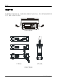
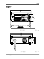
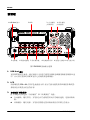
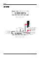
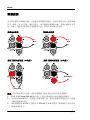
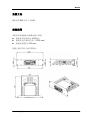
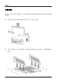
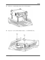
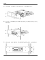
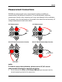
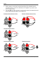
RIGOL 快速指南 DM3068 数字万用表 2014 年 2 月 RIGOL Technologies, Inc. RIGOL 保证和声明 版权 © 2010 北京普源精电科技有限公司版权所有。 商标信息 RIGOL 是北京普源精电科技有限公司的注册商标。 文档编号 QGC06002-1110 声明 本公司产品受已获准及尚在审批的中华人民共和国专利的保护。 本公司保留改变规格及价格的权利。 本手册提供的信息取代以往出版的所有资料。 对于本手册可能包含的错误,或因手册所提供的信息及演绎的功能,以及因使用 本手册而导致的任何偶然或继发的损失,RIGOL 概不负责。 未经 RIGOL 事先书面许可不得影印复制或改编本手册的任何部分。 产品认证 RIGOL 认证本产品符合中国国家产品标准和行业产品标准及 ISO9001:2008 标准和 ISO14001:2004 标准,并进一步认证本产品符合其它国际标准组织成员的相关标准。 联系我们 如您在使用此产品或本手册的过程中有任何问题或需求,可与 RIGOL 联系: 电子邮箱:[email protected] 网址:www.rigol.com DM3068 快速指南 I RIGOL 目 录 保证和声明 ................................................................................................. I 目 录 ........................................................................................................II 安全要求 ................................................................................................. III 一般安全概要 ......................................................................................... III 安全术语和符号 ...................................................................................... VI 保养与清洁 ............................................................................................ VII 环境注意事项 ....................................................................................... VIII 快速入门 .................................................................................................... 1 一般性检查 ...............................................................................................1 调整手柄 ..................................................................................................2 外观尺寸 ..................................................................................................3 前面板 .....................................................................................................4 后面板 .....................................................................................................7 用户界面 ................................................................................................ 10 首次使用万用表 ...................................................................................... 11 测量连接 ................................................................................................ 12 使用内置帮助 ......................................................................................... 15 使用机架 ................................................................................................ 16 故障处理 .................................................................................................. 21 II DM3068 快速指南 RIGOL 安全要求 一般安全概要 了解下列安全性预防措施,以避免受伤,并防止损坏本产品或与本产品连接的任何产 品。为避免可能的危险,请务必按照规定使用本产品。 使用正确的电源线。 只允许使用所在国家认可的本产品专用电源线。 将产品接地。 本产品通过电源电缆的保护接地线接地。为避免电击,在连接本产品的任何输入或输 出端子之前,请确保本产品电源电缆的接地端子与保护接地端可靠连接。 查看所有终端额定值。 为避免起火和过大电流的冲击,请查看产品上所有的额定值和标记说明,请在连接产 品前查阅产品手册以了解额定值的详细信息。 使用合适的过压保护。 确保没有过电压(如由雷电造成的电压)到达该产品。否则操作人员可能有遭受电击 的危险。 请勿开盖操作。 请勿在仪器机箱打开时运行本产品。 使用合适的保险丝。 只允许使用本产品指定规格的保险丝。 避免电路外露。 电源接通后,请勿接触外露的接头和元件。 怀疑产品出故障时,请勿进行操作。 如果您怀疑本产品出现故障,请联络RIGOL授权的维修人员进行检测。任何维护、调 整或零件更换必须由RIGOL授权的维修人员执行。 保持适当的通风。 通风不良会引起仪器温度升高,进而引起仪器损坏。使用时应保持良好的通风,定期 DM3068 快速指南 III RIGOL 检查通风口和风扇。 请勿在潮湿环境下操作。 为避免仪器内部电路短路或发生电击的危险,请勿在潮湿环境下操作仪器。 请勿在易燃易爆的环境下操作。 为避免仪器损坏或人身伤害,请勿在易燃易爆的环境下操作仪器。 请保持产品表面的清洁和干燥。 为避免灰尘或空气中的水分影响仪器性能,请保持产品表面的清洁和干燥。 防静电保护。 静电会造成仪器损坏,应尽可能在防静电区进行测试。在连接电缆到仪器前,应将其 内外导体短暂接地以释放静电。 注意搬运安全。 为避免仪器在搬运过程中滑落,造成仪器面板上的按键、旋钮或接口等部件损坏,请 注意搬运安全。 所有型号的干扰试验符合 A 类标准,基于 EN 61326:1997+A1+A2+A3 的标准, 但是不符合 B 类标准。 输入端子保护极限 保护极限是为输入端子定义的: 1. 主输入(HI 和 LO)端子。 HI 和 LO 输入端子用于电压、电阻、电容、连通性、频率和二极管测试测量。这 两个端子定义了以下两个保护极限: 1) HI 到 LO 保护极限。HI 到 LO 保护极限为 1000 VDC 或 750 VAC,这也是可 测量的最大电压。此极限也可表示为最大 1000 Vpk。 2) LO 到接地保护极限。LO 输入端子相对于地来说最大可以安全地“浮动”到 500 Vpk。 HI 端子的保护极限相对于地来说最大为 1000 Vpk。因此, “浮动”电压和测得 的电压之和不得超过 1000 Vpk。 2. 取样(HI Sense 和 LO Sense/200mA)端子。 HI Sense 和 LO Sense/200mA 端子用于四线电阻测试测量。这两个端子定义了以 下两个保护极限: 1) HI Sense 到 LO Sense/200mA 保护极限。HI Sense 和 LO Sense/200mA 保 IV DM3068 快速指南 RIGOL 护极限为 200Vpk。 2) LO Sense/200mA 到 LO 保护极限。LO Sense/200 mA 和 LO 保护极限为 0.5 Vpk,后面板电流输入保险丝对流过 LO Sense/200 mA 端子的电流提供最大 500mA 保护极限。 3. 电流输入(10 A 和 LO Sense/200 mA)端子。 10 A 和 LO 端子用于 2 A 和 10 A 量程电流测试测量,万用表内部保险丝对流过 10 A 端子的电流提供最大 10A 保护极限。 LO Sense/200 mA 和 LO 端子用于 200uA 至 200mA 量程电流测试测量,后面板电流输入保险丝对流过 LO Sense/200mA 端子的电流提供最大 500mA 保护极限。 注意: 为了避免保险丝熔断或损坏万用表,请务必遵循如下提示使用电流输入端子。 1) 10 A 和 LO Sense/200 mA 输入端子不允许同时被接入到电流测量回路中。 2) 如果被测电流 AC+DC 有效值介于 200 mA 至 10 A 范围内,测试测量只允许 使用 10 A 和 LO 端子。 3) 进行电流测试测量时,在接通万用表电源之前,请务必根据预期的电流大小 选择正确的电流输入端子。 4) 输入至 10 A 端子的电流最大不得超过 13.5 A,否则,万用表内部保险丝将 熔断;输入至 LO Sense/200 mA 端子的电流最大不得超过 650 mA,否则, 后面板电流输入保险丝将熔断。 IEC 测量类别 II 过压保护 为了避免电击危险,DM3068 数字万用表为同时满足以下两个条件的电力干线连接提 供过压保护: 1. HI 和 LO 输入端子在测量类别 II 条件下(如下所述)连接到电力干线。 2. 电力干线的最大线路电压为 300 VAC。 警告:IEC 测量类别 II 包括通过分支电路上的某一插座连接到电力干线的电气装置。 这些装置包括大多数小家电、测试设备以及插到支路插座上的其他设备。 DM3068 可用于进行这样的测量:HI 和 LO 输入端子连接到这些设备中的电力干线(最 高 300 VAC) ,或自身连接到支路插座。不过,DM3068 的 HI 和 LO 输入端子不能连 接到永久安装的电气装置中的电力干线,如主断路器配电盘、分配电盘断路盒或永久 连线的电机。这些装置和电路容易出现超过 DM3068 保护极限的过压现象。 注意:高于 300 VAC 的电压只能与电力干线断开的电路中测量。不过,与电力干线断 开的电路中也存在瞬态过电压。DM3068 可以安全地承受高达 2500 Vpk 的偶然瞬态 过电压。请勿使用该设备来测量瞬态过电压可能超出这一水平的电路。 DM3068 快速指南 V RIGOL 安全术语和符号 本手册中的术语。以下术语可能出现在本手册中: 警告 警告性声明指出可能会危害操作人员生命安全的条件和行为。 注意 注意性声明指出可能导致本产品损坏或数据丢失的条件和行为。 CAT I(1000V) IEC 测量类别 I。HI-LO 端最大可测量电压为 1000Vpk。 CAT II(300V) IEC 测量类别 II。在类别 II 过压情况下,输入可能连接到电力干线(高达 300 VAC)。 产品上的术语。以下术语可能出现在产品上: 危险 警告 注意 坏。 表示您如果进行此操作可能会立即对您造成危害。 表示您如果进行此操作可能会对您造成潜在的危害。 表示您如果进行此操作可能会对本产品或连接到本产品的其他设备造成损 产品上的符号。以下符号可能出现在产品上: 高电压 VI 安全警告 保护性接地端 壳体接地端 测量接地端 DM3068 快速指南 RIGOL 保养与清洁 保养 请勿将仪器放置在长时间受到日照的地方。 清洁 请根据使用情况经常对仪器进行清洁。方法如下: 1. 断开电源。 2. 用潮湿但不滴水的软布(可使用柔和的清洁剂或清水)擦试仪器外部的浮尘。清 洁带有液晶显示屏的仪器时,请注意不要划伤 LCD 保护屏。 注意 请勿使任何腐蚀性的液体沾到仪器上,以免损坏仪器。 警告 重新通电之前,请确认仪器已经干透,避免因水分造成电气短路甚至人身 伤害。 DM3068 快速指南 VII RIGOL 环境注意事项 以下符号表明本产品符合欧盟根据关于废弃电气、电子设备(WEEE)的Directive 2002/96/EC 所制定的要求。 设备回收 本产品中包含的某些物质可能会对环境或人体健康有害,为避免将有害物质释放到环 境中或危害人体健康,建议采用适当的方法回收本产品,以确保大部分材料可正确地 重复使用或回收。有关处理或回收的信息,请与当地权威机构联系。 VIII DM3068 快速指南 RIGOL 快速入门 一般性检查 1. 检查运输包装 如运输包装已损坏,请保留被损坏的包装或防震材料,直到货物经过完全检查且 仪器通过电性和机械测试。 因运输造成仪器损坏,由发货方和承运方联系赔偿事宜。RIGOL公司恕不进行 免费维修或更换。 2. 检查整机 若存在机械损坏或缺失,或者仪器未通过电性和机械测试,请联系您的 RIGOL 经销商。 3. 检查随机附件 请根据装箱单检查随机附件,如有损坏或缺失,请联系您的RIGOL经销商。 DM3068 快速指南 1 RIGOL 调整手柄 要调整数字万用表的手柄,请握住表体两侧的手柄并向外拉。然后将手柄旋转到所需 位置。操作方法如下图所示。 图 1 调整手柄 平放位置 移动位置 图 2 放置仪器 2 DM3068 快速指南 RIGOL 外观尺寸 图 3 正视图 图 4 侧视图 DM3068 快速指南 单位:mm 单位:mm 3 RIGOL 前面板 1.USB Host 接口 2.LCD 3. 自动触发 /读数保持 4.单次触发 /本地切换 MENU FUNC 5.电源键 6.测量功能键 7.菜单操作键 8.高级操作菜单 9.量程/方向键 10.信号输入端 图 5 DM3068 前面板示意图 1. USB Host 接口 支持 FAT 格式的 U 盘。通过该接口可以将当前的仪器状态或测量数据存储到 U 盘 中,并可以在需要时读取 U 盘中已存储的状态或数据。 2. LCD 高清晰度的 256 x 64 点阵单色液晶显示屏,显示当前功能的菜单和测量参数设置、 系统状态以及提示消息等内容。 3. 自动触发/读数保持 按下该键可切换选择“自动触发”和“读数保持”功能。 自动触发:键灯常亮。万用表会以当前配置所允许的最快速度,连续读取读 数。 读数保持:键灯闪烁。万用表获得稳定的读数并保持在屏幕上的显示。 4 DM3068 快速指南 RIGOL 4. 单次触发/本地切换 前面板操作时,按下该键选择单次触发,万用表产生一个读数或指定个数(采样 数)的读数,然后等待下一个触发。万用表处于远程模式时,按下该键将切换到 本地模式。 5. 电源键 按下该键可启动或关闭万用表。您可以设置该按键的使用状态。方法如下: 按 System 配置 前开关,选择“打开”或“关闭”。 6. 测量功能键 基本测量功能键: 直流电压测量(DCV) 。 交流电压测量(ACV) 。 直流电流测量(DCI) 。 交流电流测量(ACI) 。 电阻测量(OHM) 。 电容测量(CAP) 。 连通性测试(CONT) 。 二极管测试(DIODE) 。 频率/周期测量(FREQ/PERIOD) 。 任意传感器测量(SENSOR)。支持的传感器类型包括:DCV,DCI,2WR, 4WR,FREQ,TC(热电偶),RTD(热电阻),THERM(热敏电阻) 。 常用/实用功能键: 可快速存储或调用 10 组仪器设置。 第二功能键。 打开双显功能。 配合 快速保存当前仪器配置。 快速打开相对测量(REL)设置界面。 7. 菜单操作键 按下任一软键激活对应的菜单。 DM3068 快速指南 5 RIGOL 8. 高级操作菜单 提供各种测量功能下的测量参数设置。 对测量结果进行数学运算(统计、P/F、dBm、dB、相对)并提供实时 测量的“趋势图”和“直方图” 。 提供自动触发、单次触发、外部触发、电平触发;可设置读数保持; 可设置每次触发的采样数目、读数前的延迟时间和触发输入信号的边 沿;可设置触发输出。 支持对内部存储区和外部 USB 存储设备中的仪器参数文件和数据文件 进行存储、调用和删除。 可选择万用表支持的命令集;配置接口参数;设置系统信息;检测万 用表并查看错误消息。 提供常用操作的帮助信息以及如何使用在线帮助的方法。万用表提供 前面板任一按键和菜单软键的使用帮助。 9. 量程/方向键 按下该键启用自动量程。 配置测量参数。 参数输入时,用于选择光标位置。 按上(下)方向键手动增大(减小)测量量程。 参数输入时,用于输入不同的数值。 用于翻页。 10. 信号输入端 被测信号(器件)通过该输入端被接入万用表。不同测量对象的测量连接方法不 同,具体请参考“测量连接”中的说明。 6 DM3068 快速指南 RIGOL 后面板 1.电流输入保险丝 2. LAN 接口 SEL 6.外部触发输入 5.VMC 输出 3.GPIB 接口 ~Line(25VA Max) 4.电源插孔 Fuse 115 AC 100-120V 45-440Hz AC 250V T250mA 230 AC 200-240V 45-66Hz AC 250V T125mA 8.RS232 接口 7.USB Device 接口 10.电压选择器 9.电源保险丝 11.电源开关 图 6 DM3068 后面板示意图 1. 电流输入保险丝 万用表分别使用两种保险丝提供对小电流量程和大电流量程时的输入保护。万用 表内部保险丝对大电流量程输入提供最大10A保护极限,输入电流超过13.5 A时 保险丝熔断。后面板电流输入保险丝对小电流量程输入提供最大500mA保护极 限,流入电流超过650 mA时保险丝熔断。万用表在出厂时已安装了大电流输入保 险丝。如需更换小电流量程保险丝,请按照下面的方法进行更换: 1) 关闭万用表电源。 2) 使用一字螺丝刀沿图中所示方向旋转后用力拔出保险丝座。 3) 更换指定规格的保险丝。 4) 将保险丝座重新装入卡槽中。 注意,大电流输入的保险丝位于仪器内部,不允许用户更换。如需更换,需将万 用表返厂。 DM3068 快速指南 7 RIGOL 2. LAN接口 通过该接口将万用表连接至局域网中,进行远程控制。万用表符合LXI-C类仪器标 准,可与其他标准设备快速搭建测试系统,轻松实现基于LAN的系统集成。 3. GPIB接口 符合IEEE-488.2规范。 4. 电源插孔 本万用表可输入两种规格的交流电源。使用附件提供的电源线将交流电通过该插 孔接入万用表中。注意,连接交流电之前,请先选择正确的电压档位(使用电压 选择器) 。 图7 连接电源线 5. VMC输出 VM输出打开时( 输出 “打开” ) ,万用表在每次完成测量后,会从[VM Comp]连接器输出一个负脉冲(Low-True Pulse)。 6. 外触发输入 您可以将触发脉冲加到[Ext Trig]连接器来触发万用表。此时,需要选择外触发 源( 触发源 外部)。 7. USB Device接口 支持 USB-TMC 设备。可与计算机通信,通过上位机软件控制万用表。 8. RS232接口 可与计算机通信,通过上位机软件控制万用表。该接口还可用于输出P/F测试结果。 8 DM3068 快速指南 RIGOL 9. 电源保险丝 万用表在出厂时已安装了一个电源保险丝。如需更换保险丝,请按照下面的方法 进行更换: 1) 关闭万用表电源。 2) 使用一字螺丝刀按下卡舌(虚线箭头所指位置),之后拔出保险丝座。 3) 在电压选择器处选择正确的电压档位。 4) 更换指定规格的保险丝。 5) 将保险丝座重新装入卡槽中。 图 8 更换电源保险丝 注意 为避免电击或火灾,请使用指定规格的保险丝并确保保险丝支架没有短路。 10. 电压选择器 请根据您所使用的交流电规格选择正确的电压档位。 提供两种交流输入电压档位:115 V、230 V。 11. 电源开关 接通或切断电源的连接。如果前面板电源软开关已禁用(按 System 配 置 前开关 “关闭”),那么使用此开关接通电源后,将直接启动仪器。 DM3068 快速指南 9 RIGOL 用户界面 图 9 用户界面(单显) 数学 量程 测量参数 REL 打开 主显示测量功能 运行指示 主显示测量结果 统计 最大 最小 平均 P/F dBm dB 模式 LXI:LXI 连接成功 Rmt:远程控制 Local:本地控制 :USB 存储 副显示测量结果 副显示测量功能 操作菜单 图 10 用户界面(双显) 10 DM3068 快速指南 RIGOL 首次使用万用表 首次使用万用表时,请参考下面的步骤启动万用表。 1. 连接 AC 电源 1) 根据您的供电电压调节万用表后面板的电源电压选择器。 2) 使用附件提供的电源线将万用表连接至交流电源中。 2. 启动万用表 打开电源插孔下面的电源开关。此时,如果万用表中的“前开关”设置为“关闭” ( 键 System 配置 前开关 “关闭” ) ,仪器会直接启动。否则, 请按下前面板的电源键启动仪器。 3. 开机过程 1) 正常启动:开机过程中,仪器执行自检,自检结束后显示用户界面。 2) 带含升级文件的 U 盘启动:开机过程中,若仪器检测到升级文件,将直接升 级至该软件版本,然后启动仪器。 4. 若仪器没有正常启动,请按照下面步骤进行检查: 1) 检查电源线是否接触良好。 2) 检查后面板电源开关是否已经打开。 3) 如经检查无误后,仪器仍未启动,请检查电源保险丝是否已熔断,如有必要, 请更换保险丝。 4) 若经上述检查无误后,仪器仍未启动,请与 RIGOL 联系。 DM3068 快速指南 11 RIGOL 测量连接 本万用表提供多种测量功能。在选择所需的测量功能后,请按下图所示的方法将被测 信号(器件)接入万用表。测量过程中,请勿随意切换测量功能,否则可能损害万用 表。例如:当测量引线连接至电流插孔中时,请勿用其去测交流电压。 直流电压测量 直流/交流电流测量(小电流) 交流电压测量 + + DCV ACV - - 直流/交流电流测量(大电流) - DCI/ACI + + DCI/ACI - 注意:为了避免损坏万用表,请务必遵循如下提示进行直流/交流电流测量。 1. 10 A 和 LO Sense/200 mA 输入端子不允许同时被接入到电流测量回路中。 2. 进行电流测试测量时,在接通万用表电源之前,请务必根据预期的电流大小选择 正确的电流输入端子。 3. 如果被测电流 AC+DC 有效值介于 200 mA 至 10 A 范围内,测试测量只允许使用 10 A 和 LO 端子。 12 DM3068 快速指南 RIGOL 二线电阻测量 四线电阻测量 + + 2WR 4WR - - 电容测量 + Capacitance - 连通性测量 二极管测量 + Open or Closed Circuit - DM3068 快速指南 + Open or Closed Circuit - 13 RIGOL 任意传感器测量(适用于DCV、2WR、 频率/周期测量 FREQ、TC、2线RTD和THERM型传感器) + + AC Signal Sensor - - 任意传感器测量 任意传感器测量 (适用于DCI型传感器) (适用于4WR和4线RTD型传感器) + Sensor - + Sensor - 14 DM3068 快速指南 RIGOL 使用内置帮助 按 键,打开下图所示界面。提供常用操作的帮助信息以及如何使用在线帮助的 方法。万用表提供前面板任一按键和菜单软键的使用帮助。 图 11 帮助列表 表 1 帮助菜单 菜单 说明 选中 读取当前选中的帮助信息。 向上移动光标选择所需的帮助信息。 向下移动光标选择所需的帮助信息。 进入上一页帮助信息。 进入下一页帮助信息。 返回上一层操作菜单。 帮助主题列表: 1. 测试表笔连接 2. 基本测量 3. 数学测量 4. 任意传感器测量 5. 存储和读取 6. 设置 Utility 7. 输入输出接口 8. 在线帮助 9. 更换电力线保险丝 10. 技术支持 DM3068 快速指南 15 RIGOL 使用机架 DM3068 万用表可安装到 19 英寸标准机柜内。安装前,请拆除万用表的包装或防震材 料。 部件清单 表 2 机架连接套件清单 图标 名称 数量 零件编号 描述 1-1 前面板 1 RM-DM-3-01 - 1-2 底板 1 RM-DM-3-02 - 1-3 左侧板 1 RM-DM-3-03 - 1-4 右侧板 1 RM-DM-3-04 - 1-5 压脚 2 RM-DM-3-05 2-1 M4 螺钉 16 RM-SCREW-01 M4*8 十一字切沟盘头机械牙螺钉 2-2 M6 螺钉 4 RM-SCREW-02 M6*20 十一字切沟盘头机械牙螺钉 2-3 M6 螺母 4 RM-SCREW-03 M6*4 带定位锁片机械牙方螺母 2-1 16 2-2 2-3 DM3068 快速指南 RIGOL 安装工具 推荐使用 PH2 号头十字改锥。 安装空间 本机架安装到机柜内须满足如下要求: 机柜必须为 19 英寸标准机柜。 机柜至少有 3U 的空间(133.5 mm) 。 机柜内深度至少 400 mm。 仪器上架后的尺寸如下图所示: DM3068 快速指南 17 RIGOL 安装步骤 仅授权人员方可执行安装操作,不正确的操作可能导致仪器损坏或者不能正确安装到 机架内。 1. 拆卸手柄:握住表体两侧的手柄并向外拉,然后向上提。 2. 安装左右侧板:将左右侧板的卡位对准底板的豁口后插入底板,用 8 颗 M4 螺钉 固定。 18 DM3068 快速指南 RIGOL 3. 放置仪器:将仪器的垫脚对准相应的孔后将其放到底板上。 4. 固定仪器:用两个压脚将仪器紧扣在底板上,用 4 颗 M4 螺钉固定。 DM3068 快速指南 19 RIGOL 5. 安装前面板:将前面板开口对准仪器的前脸,用 4 颗 M4 螺钉固定。 6. 装入机柜:用 4 颗 M6 螺钉和 4 颗 M6 方螺母将固定好仪器的机架安装在 19 英寸 标准机柜内。 7. 安装后注意:机架占 3U 高度,箭头所指的孔为机架的安装孔,注意对准安装。 20 DM3068 快速指南 RIGOL 故障处理 下面列举了万用表在使用过程中可能出现的故障及排查方法。当您遇到这些故障时, 请按照相应的步骤进行处理,如不能处理,请与 RIGOL 联系,同时请提供您机器的 设备信息(获取方法:Utility 检测 信息) 。 1. 按下电源开关,万用表仍然黑屏,没有任何显示: (1) 检查电源插头是否接好。 (2) 检查背面的电源总开关是否已经打开。 (3) 检查背面的电源输入的保险管是否已经熔断。如果已经熔断,请按要求更换 保险管。 (4) 做完上述检查后,重新启动仪器。 (5) 如果仍然无法正常使用本产品,请与 RIGOL 联系。 2. 接入一个电流信号,读数没有任何改变: (1) 检查表笔是否正确插入电流插孔和 LO 插孔。 (2) 检查背面的电流档位保险管是否已经熔断。 (3) 检查测量档位是否已经正确切换到 DCI 或者 ACI 档位。 (4) 检查是否由于输入的是 ACI,而档位却是处于 DCI 档位。 3. 当接入一个 DC 信号,读数显示不正常: (1) 检查表笔是否正确插入电流插孔和 LO 插孔。 (2) 检查背面的电流档位保险管是否已经熔断。 (3) 检查测量档位是否已经正确切换到 DCI 或者 DCV 档位。 (4) 检查是否由于输入的是 DCI,而档位却处于 ACI 档位。 4. U 盘设备不能被识别: (1) 检查 U 盘是否可以正常工作。 (2) 确认使用的为 Flash 型 U 盘,本仪器不支持硬盘型 U 盘。 (3) 确认使用的 U 盘大小,推荐使用不大于 4G bytes 的 U 盘。 (4) 重新启动仪器,再插入 U 盘进行检查。 (5) 如果仍然无法正常使用 U 盘,请与 RIGOL 联系。 DM3068 快速指南 21 RIGOL Quick Guide DM3068 Digital Multimeter Feb. 2014 RIGOL Technologies, Inc. RIGOL Guaranty and Declaration Copyright © 2010 RIGOL Technologies, Inc. All Rights Reserved. Trademark Information RIGOL is a registered trademark of RIGOL Technologies, Inc. Publication Number QGC06102-1110 Notices RIGOL products are protected by patent law in and outside of P.R.C. RIGOL reserves the right to modify or change parts of or all the specifications and pricing policies at company’s sole decision. Information in this publication replaces all previously corresponding material. RIGOL shall not be liable for losses caused by either incidental or consequential in connection with the furnishing, use or performance of this manual as well as any information contained. Any part of this document is forbidden to copy or photocopy or rearrange without prior written approval of RIGOL. Product Certification RIGOL guarantees this product conforms to the national and industrial standards in China as well as the ISO9001:2008 standard and the ISO14001:2004 standard. Other international standard conformance certification is in progress. Contact Us If you have any problem or requirement when using our products or this manual, please contact RIGOL. E-mail: [email protected] Websites: www.rigol.com DM3068 Quick Guide I RIGOL Contents Guaranty and Declaration......................................................................... I Content ...................................................................................................II Safety Requirement............................................................................... III General Safety Summary.......................................................................... III Safety Terms and Symbols ...................................................................... VII General Care and Cleaning ..................................................................... VIII Environmental Considerations................................................................... IX Quick Start ............................................................................................... 1 General Inspection ....................................................................................1 Handle Adjustment....................................................................................2 Appearance and Dimensions ......................................................................3 The Front Panel ........................................................................................4 The Rear Panel .........................................................................................8 User Interface......................................................................................... 11 First-use of Multimeter............................................................................. 12 Measurement Connections ....................................................................... 13 Using the Built-in Help System.................................................................. 16 Using a Rackmount Kit............................................................................. 17 Troubleshooting ..................................................................................... 22 II DM3068 Quick Guide RIGOL Safety Requirement General Safety Summary Please review the following safety precautions carefully before putting the instrument into operation so as to avoid any personal injuries or damages to the instrument and any product connected to it. To prevent potential hazards, please use the instrument only specified by this manual. Use Proper Power Cord. Only the power cord designed for the instrument and authorized by local country could be used. Ground The Instrument. The instrument is grounded through the Protective Earth lead of the power cord. To avoid electric shock, it is essential to connect the earth terminal of power cord to the Protective Earth terminal before any inputs or outputs. Observe All Terminal Ratings. To avoid fire or shock hazard, observe all ratings and markers on the instrument and check your manual for more information about ratings before connecting. Use Proper Overvoltage Protection. Make sure that no overvoltage (such as that caused by a thunderstorm) can reach the product, or else the operator might expose to danger of electrical shock. Do Not Operate Without Covers. Do not operate the instrument with covers or panels removed. Use Proper Fuse. Please use the specified fuses. Avoid Circuit or Wire Exposure. Do not touch exposed junctions and components when the unit is powered. DM3068 Quick Guide III RIGOL Do Not Operate With Suspected Failures. If you suspect damage occurs to the instrument, have it inspected by qualified service personnel before further operations. Any maintenance, adjustment or replacement especially to circuits or accessories must be performed by RIGOL authorized personnel. Keep Well Ventilation. Inadequate ventilation may cause increasing of temperature or damages to the device. So please keep well ventilated and inspect the intake and fan regularly. Do Not Operate in Wet Conditions. In order to avoid short circuiting to the interior of the device or electric shock, please do not operate in a humid environment. Do Not Operate in an Explosive Atmosphere. In order to avoid damages to the device or personal injuries, it is important to operate the device away from an explosive atmosphere. Keep Product Surfaces Clean and Dry. To avoid the influence of dust and/or moisture in air, please keep the surface of device clean and dry. Electrostatic Prevention. Operate in an electrostatic discharge protective area environment to avoid damages induced by static discharges. Always ground both the internal and external conductors of the cable to release static before connecting. Handling Safety Please handle with care during transportation to avoid damages to keys, knob and, interfaces as well as other parts on the panels. The disturbance tests of all models conform to the P/F values of A based on the standard of EN 61326: 1997+A1+A2+A3 instead of P/F values of B. IV DM3068 Quick Guide RIGOL Input Terminal Protection Limit The protection limit applies to input terminals: 1. Main input (HI and LO) terminals HI and LO terminals are used for Voltage, Resistance, Capacitance, Continuity, Frequency and Diodes measurements and should be used under the following two conditions: 1) HI-LO protection limit: at most 1000 VDC or 750 VAC, this is also the maximum measurable voltage. The limit can be expressed as 1000 Vpk. 2) LO-ground protection limit: at most 500 Vpk (relative) is allowed to float at LO terminal with safety. Since the HI terminal holds a maximum protection of 1000 Vpk relative to the ground, the sum of the “float” and measured voltages cannot exceed 1000 Vpk. 2. Sampling (HI Sense and LO Sense/200 mA) terminals HI Sense and LO Sense/200 mA terminals are used for 4-Wire Resistance measurement and should be used under the following two conditions: 1) HI Sense-LO Sense/200 mA protection limit: 200 Vpk. 2) LO Sense/200 mA-LO protection limits: 0.5 Vpk. The current input fuse on the rear panel provides the current passing through LO Sense/200 mA up to 500 mA protection. 3. Current input (10 A and Sense/200 mA) terminals 10 A and LO terminals are used for current measurements of 2 A and 10 A. The maximum current which goes through the 10 A terminal is limited to 10 A by the internal fuse. LO Sense/200 mA and LO terminals are used for current measurements ranging from 200 µA to 200 mA. The maximum current which go through the LO Sense/200 mA terminal is limited to 500 mA by the internal fuse. NOTE: In order to prevent the fuse from blowing out and protect the multimeter, please use the current input terminals according to the following requirements: 1) Do not connect the 10 A and LO Sense/200 mA input terminals into the current measuring circuit at the same time. 2) Only use 10 A and LO terminals for measurements when the measured DM3068 Quick Guide V RIGOL current AC+DC RMS value goes within 200 mA and 10 A. 3) Select a proper current input terminal according to the estimated current magnitude before connect the multimeter to AC supplies if you want to use current measurement. 4) The current into 10 A cannot exceed 13.5 A, otherwise it will blow out the internal fuse; while the current into the LO Sense/200 mA terminal cannot exceed 650 mA, otherwise the current fuse from the rear panel may be blown out. IEC II Overvoltage Protection In order to prevent electric shock, DM3068 provides overvoltage protection for line-voltage mains connections meeting both of the following conditions: 1. The HI and LO input terminals are connected to the mains under Measurement Category II conditions, defined below. 2. The mains are limited to a maximum line voltage of 300 VAC. WARNING: IEC II includes electrical devices connected to mains at an outlet on a branch circuit. Such devices include most small appliances, test equipments and other devices that inserted into a branch socket. DM3068 may be used to make measurements with the HI and LO inputs connected to mains in such devices (up to 300 VAC), or to the branch socket itself. However, DM3068 may be used with its HI and LO inputs connected to mains from neither permanently installed electrical device such as a main circuit-breaker panel, sub-panel disconnected box nor wired motors. Such devices and circuits are readily to beyond the protection from DM3068. NOTE: Voltages above 300 VAC may be measured only in circuits that are isolated from mains. However, a transient overvoltage is also present in such circuits. DM3068 was designed to safely withstand occasional transient overvoltage up to 2500 Vpk. Do not use this device to measure circuits whose transient overvoltage may exceed this level. VI DM3068 Quick Guide RIGOL Safety Terms and Symbols Terms in this Manual. These terms may appear in this manual: WARNING Warning statements indicate the conditions or practices that could result in injury or loss of life. CAUTION Caution statements indicate the conditions or practices that could result in damage to this product or other property. CAT I (1000V) IEC Measurement Category I. The maximum voltage can be measured by HI-LO terminal is 1000Vpk. CAT II (300V) IEC Measurement Category II. Inputs may be connected to mains (up to 300VAC) in the case of overvoltage in Category II. Terms on the Product. These terms may appear on the product: DANGER indicates an injury or hazard may immediately happen. WARNING indicates an injury or hazard may be accessible potentially. CAUTION indicates a potential damage to the instrument or other property might occur. Symbols on the Product. These symbols may appear on the product: Hazardous Voltage DM3068 Quick Guide Safety Warning Protective Earth Terminal Chassis Ground Test Ground VII RIGOL General Care and Cleaning General Care: Do not store or leave the instrument in where the instrument will be exposed to direct sunlight for long periods of time. Cleaning: Clean the instrument regularly according to its operating conditions. To clean the exterior surface, perform the following steps: 1. Disconnect the instrument from all power sources. 2. Clean the loose dust on the outside of the instrument with a lint- free cloth (with a mild detergent and water). When clean the LCD, take care to avoid scarifying it. CAUTION To avoid damages to the instrument, do not expose them to liquids which are corrosive. WARNING To avoid injury resulting from short circuit, make sure the instrument is completely dry before reconnecting into a power source. VIII DM3068 Quick Guide RIGOL Environmental Considerations The following symbol indicates that this product complies with the applicable European Union requirements according to Directives 2002/96/EC on waste electrical and electronic equipment (WEEE) and batteries. Product End-of-Life Handling The equipment may contain substances that could be harmful to the environment or human health. In order to avoid release of such substances into the environment and harmful to human health, we encourage you to recycle this product in an appropriate system that will ensure that most of the materials are reused or recycled appropriately. Please contact your local authorities for disposal or recycling information. DM3068 Quick Guide IX RIGOL Quick Start General Inspection 1. Inspect the shipping container for damage Keep the damaged shipping container or cushioning material until the contents of the shipment have been checked for completeness and the instrument has passed both electrical and mechanical tests. The consigner or carrier shall be liable for the damage to the instrument resulting from shipment. RIGOL would not be responsible for free maintenance/rework or replacement of the unit. 2. Inspect the instrument In case of any damage, or defect, or failure, notify your RIGOL sales representative. 3. Check the accessories Please check the accessories according to the packing lists. If the accessories are incomplete or damaged, please contact your RIGOL sales representative. DM3068 Quick Guide 1 RIGOL Handle Adjustment To adjust the handle position of the multimeter, grip the handle in both sides and pull it outward, then rotate the handle to a desired position, see figure below. Figure 1 Handle Adjustment Viewing Position Carrying Position Figure 2 Locate the Multimeter 2 DM3068 Quick Guide RIGOL Appearance and Dimensions Figure 3 Front Elevation Figure 4 Side Elevation DM3068 Quick Guide Unit: mm Unit: mm 3 RIGOL The Front Panel 1.USB Host 2.LCD 3.Auto Trigger /Reading Hold 4.Single Trigger /Local Mode MENU FUNC 5.Power 6. Measurement Button Function Keys 7. Menu Operation 8.Advanced 9.Range 10.Signal Input Keys Menu Keys /Direction Keys Figure 5 Front Panel Overview 1. USB Host It supports all FAT-format USB flash devices. By using this interface, users can easily save the current instrument status and measured data into such device for future use. 2. LCD This is a 256 x 64 monochrome LCD that can display the current function menus, measurement parameters, system configuration and status and so on. 3. Auto Trigger/Reading Hold Continuously pressing this key can switch between auto trigger and reading hold functions. Auto Trigger: the backlight always on; the multimeter continuously takes readings at the fastest rate possible for the present configuration. 4 DM3068 Quick Guide RIGOL Reading Hold: the backlight blinks; the multimeter obtains a stable reading and displays. 4. Single Trigger/Local Mode Pressing this key during the front panel operation will cause the multimeter generate one reading or specified number of readings (S NO.) and then wait for the next trigger. Whatever, this key is also an access to local mode from remote control. 5. Power Button Turns on or off the multimeter. Users can enable or disable this key as required. Press 6. System Cfg Switch and select On or Off. Measurement Function Keys Basic Measurement Keys DC Voltage Measurement (DCV) AC Voltage Measurement (ACV) DC Current Measurement (DCI) AC Current Measurement (ACI) Resistance Measurement (OHM) Capacitance Measurement (CAP) Continuity Test (CONT) Diode Test (DIODE) Frequency/Period Measurements (FREQ/PERIOD) Any Sensor Measurements (SENSOR), such as DCV, DCI, 2WR, 4WR, FREQ, TC (thermoelectric couple), RTD (resistance temperature detectors), THERM (thermistor). Common Function Keys Quickly save or recall at least 10 groups of instrument settings. Secondary Function key Enables the dual display. Quickly saves the current instrument configuration in connection DM3068 Quick Guide with . Quickly enters the setting interface of relative measurement. 5 RIGOL 7. Operation Menu Keys Activates the corresponding menu. 8. Assistant Functions Sets all the measurement parameters. Performs math operations (statistic, P/F, dBm, dB, REL) for measured results and displays real-time measurements in trend graph and histogram. Provides auto, single, external and level trigger sources; enables to set the reading hold function, samples per trigger, delay time before reading and edge of the trigger input signal as well as the trigger output parameter. Saves, recalls and deletes data and parameter files from both internal memory and external USB devices. Sets the command set, interface parameters and system information, tests the multimeter and displays error messages. Provides common help information and the method to use built-in help. The multimeter allows users to quickly recall the help information about any front panel keys and menu softkeys. 9. Range/Direction Keys Enables auto range. 6 Configures the measurement parameters. Selects the digit position while entering a parameter. Increases or decreases the measurement range. Enters desired numeric value while setting a parameter. Pages up or down. DM3068 Quick Guide RIGOL 10. Signal Input Terminals The measured signal (device) will be connected into the multimeter through these terminals. Different measured objects have different connection methods. for details please see “Measurement Connections”. DM3068 Quick Guide 7 RIGOL The Rear Panel 1.Curr Input Fuse 2. LAN Port 3.GPIB Port SEL 6.Ext Trig Input 5.VMC Output 4.Power Socket ~Line(25VA Max) Fuse 115 AC 100-120V 45-440Hz AC 250V T250mA 230 AC 200-240V 45-66Hz AC 250V T125mA 8.RS232 Port 7.USB Device Port 10.Voltage Selector 9.Power Fuse 11.Power Switch Figure 6 Rear Panel Overview 1. 8 Curr Input Fuse The multimeter uses two kinds of fuses for protecting high and low currents and both fuses were already installed before leaving factory. The current into 10 A cannot exceed 13.5 A, otherwise it will blow out the internal fuse; while the current into LO Sense/200 mA terminal cannot exceed 650 mA, otherwise the current fuse from the rear panel may be blown out. To replace the low current fuse, please: 1) Cut off the power supply. 2) Pull out the fuse seat by turning a straight screwdriver counterclockwise as shown in the figure. 3) Place a new specified fuse. 4) Reinstall the fuse seat into the slot. NOTE: The high current fuse stands inside the multimeter and is not allowed to be replaced by users themselves. If such work must be done, send your multimeter back to the factory. DM3068 Quick Guide RIGOL 2. LAN Port Provides the multimeter an access to LAN for remote controlling. The multimeter conforms to LXI-C standards; it can be used in connection with other standard devices for a testing system built, easily approaching a LAN based system integration. 3. GPIB Port Conforms to IEEE-488.2 standards. 4. Power Socket The multimeter allows two types of AC supplies. Users should use the power cord that came with your multimeter to connect the multimeter to the AC power through this socket. Note a proper voltage scale must be first selected (through the Voltage Selector) before power connection. Figure 7 Connect the Power Cord 5. VMC Output Outputs a low-true pulse from [VM Comp] terminal after every measurement when VM output is enabled ( 6. VMC ON). Ext Trig Input Triggers the multimeter by connecting a trigger pulse through [Ext Trig] connector. Note the external trigger source must be selected ( Ext). 7. Source USB Device Port Communicates with a computer and controls your multimeter through PC software. It is available for USB-TMC devices. DM3068 Quick Guide 9 RIGOL 8. RS232 Port Provides an access for multimeter controlling through PC software and outputs P/F test result. 9. Power Fuse The multimeter is already installed a power fuse before leaving factory. To replace a new one, please: 1) Cut off the power supply. 2) Press down the block tongue using a straight screwdriver (in the direction of the dotted arrow in figure below) and pull out of the fuse seat. 3) Select a proper voltage scale. 4) Replace a specified fuse. 5) Reinstall the fuse seat into the slot. Figure 8 Replace the Power Fuse WARNING In order to avoid electric shock or fire, please just use the specified fuse and make sure the fuse holder is in good connection and not shorted. 10. Voltage Selector Select a proper voltage scale according to the used AC supply: 115 V or 230 V. 11. Power Switch Connect or disconnect the AC supply. If the front power button is disabled ( System Cfg Switch OFF), turning on this switch will directly start up the multimeter. 10 DM3068 Quick Guide RIGOL User Interface Single Display Figure 9 User Interface (Single Display) Dual Display Math Measurement parameter Range REL on Main Function Run Indication Main Reading STA MAX MIN AVG P/F dBm dB LXI: LAN Control Mode Rmt: Remote Control Local: Local Control : USB Storage Vice Reading Vice Function Operation Menus Figure 10 User Interface (Dual Display) DM3068 Quick Guide 11 RIGOL First-use of Multimeter Start your multimeter according to the following steps when first use. 1. Connect the AC Power Supply 1) Select an appropriate voltage scale according to the present AC power using the voltage selector on the rear panel. 2) Insert one end of the supplied power cord into the ac outlet and the other end into the power socket on the rear panel. 2. Turn On the Multimeter Turn on the power switch under the power socket and the power button on the front panel. Note the multimeter will directly start after you turning on the rear power switch if the front power button is disabled ( Switch OFF). System Cfg 3. Boot Process 1) Normal start: the multimeter executes self-test and then enters the user interface. 2) Start with a USB device having update file inserted: the multimeter directly updates if an update file is detected and then starts. 4. If the multimeter does not starts normally, please: 1) Make sure the power cord is in good connection. 2) Make sure the rear power switch is turned on. 3) Try to restart the multimeter, if it fails, check the power fuse and replace a new one when necessary. 4) If the problem still remains, contact RIGOL. 12 DM3068 Quick Guide RIGOL Measurement Connections DM3068 was designed with many measurement functions and different measurements have different connections. Do not discretionarily switch the measurement function when measuring as it may cause damage to the multimeter. For example, when the test leads are connected to the related current terminals, AC voltage measurement should not be taken. DCV Measurement ACV Measurement + + DCV ACV - - DCI/ACI Measurement (Low Current) DCI/ACI Measurement (High Current) - DCI/ACI + + DCI/ACI - NOTE: In order to protect the multimeter, please execute DC/AC current measurement following the requirements below: 1. Do not connect the 10 A and LO Sense/200 mA input terminals into the current measuring circuit at the same time. DM3068 Quick Guide 13 RIGOL 2. 3. Select a proper current input terminal according to the estimated current magnitude before connect the multimeter to AC supplies if you want to use current measurement. Only use 10 A and LO terminals for measurements when the measured current AC+DC RMS value goes within 200 mA and 10 A. Resistance Measurement (2-wire) Resistance Measurement (4-wire) + + 2WR 4WR - - Capacitance Measurement + Capacitance - Continuity Measurement + Open or Closed Circuit - 14 Diode Measurement + Open or Closed Circuit - DM3068 Quick Guide RIGOL Any Sensor Measurement (For DCV, 2WR, FREQ, TC, 2-wire RTD and Frequency/Period Measurement THERM sensors) + + AC Signal Sensor - Any Sensor Measurement (For DCI sensor) - Any Sensor Measurement (For DCV, 2WR, FREQ, TC, 2-wire RTD and THERM sensors) + Sensor - + Sensor - DM3068 Quick Guide 15 RIGOL Using the Built-in Help System The built-in help system provides information for users to quickly recall and use the basic functions of the instrument as well as how to use the built-in help system, including key (front panel) help and menu help. Press interface. to enter the following Figure 11 Help Topics Table 1 Help Menu Menu Description Select Go to the selected help topic Cursor up Cursor down Page up Page down Go to the previous menu Help Topics 1. The method of the test leads. 2. Common measurement. 3. Math. 4. Sensor. 5. Store and recall. 6. Utility. 7. I/O interface. 8. Online help. 9. To change the power fuse. 10. Support. 16 DM3068 Quick Guide RIGOL Using a Rackmount Kit DM3068 can be mounted in a standard 19-inch rack cabinet. Before any kit installations, please remove the package or cushioning material from the multimeter body. Kit Parts List Table 2 Kit Parts List No. Name Qty Part Number Description 1-1 Front Panel 1 RM-DM-3-01 - 1-2 Support Board 1 RM-DM-3-02 - 1-3 Left Plate 1 RM-DM-3-03 - 1-4 Right Plate 1 RM-DM-3-04 - 1-5 Fixed Finger 2 RM-DM-3-05 - 2-1 M4 Screw 16 RM-SCREW-01 M4*8 Phil-Slot Pan Head Machine Screw Nail 2-2 M6 Screw 4 RM-SCREW-02 M6*20 Phil-Slot Pan Head Machine Screw Nail M6 Nut 4 RM-SCREW-03 M6*4 Square Machine Female Screw with 2-3 Lock Blade 2-1 DM3068 Quick Guide 2-2 2-3 17 RIGOL Tool Requirements A PH2 cross screwdriver is recommended. Space Requirements The DM3068 should be mounted under the following spaces: The machine cabinet should be a standard 19-inch one. At least a 3U space (133.5 mm) should be provided by machine cabinet. The depth inside the machine cabinet should not be less than 400 mm. Dimensions after the rackmount kit on: 18 DM3068 Quick Guide RIGOL Procedure of Installation This operation should be executed only by authorized officer. Improper or incorrect operations may cause installation fails or damages to the multimeter. 1. Remove the handle from the multimeter: grip the handle in both sides and pull it outward. Then, push the unit upward to release it from the instrument. 2. Install left and right plates: aim the detents of right and left plates at the openings on support board and insert selectively, then fix them using eight M4 screws. DM3068 Quick Guide 19 RIGOL 3. Place the instrument: aim the parallels at the corresponding openings and then put the multimeter onto the support board. 4. Fix the instrument: fasten or fit the instrument tightly into the support board using two fixed fingers in connection with four M4 screws. 20 DM3068 Quick Guide RIGOL 5. Mount the front panel: aim the front panel opening at the front of instrument and fix them using four M4 screws. 6. Load into machine cabinet: mount the rack with instrument-fixed onto a standard 19-inch machine cabinet using four M6 screws and four M6 square nuts, respectively. 7. Note the rock holds a height of 3U, holes in compliance with the arrow direction are the mounting holes for rack. DM3068 Quick Guide 21 RIGOL Troubleshooting To help you solve commonly encountered problems, we have listed some typical issues with their respective solutions. If the problems persist, contact RIGOL and prepare your device information (Utility T/C Info). 1. (1) (2) (3) (4) (5) The screen still dark (no display) after power on: Check if the power cord is well connected. Check if the power switch on the rear panel is switched on. Check if the safety fuse has melted and replace a new one when necessary. Having done with the above steps, restart the instrument. If the problem persists please contact RIGOL for service options. 2. (1) (2) (3) (4) The reading is constant when a current signal is input: Check if the test lead is correctly inserted to the current and/or LO terminals. Check if the current fuse on the rear panel has melted. Check if the measurement function is switched to DCI or ACI. Check if the enabled measurement function matches with the actual input current. 3. (1) (2) (3) (4) The reading is abnormal when a DC signal is input: Check if the test lead is correctly inserted to the current and/or LO terminals. Check if the current fuse on the rear panel has melted. Check if the measurement function is switched to DCI or DCV. Check if the enabled measurement function matches with the actual input current. 4. (1) (2) (3) The USB flash device cannot be identified: Check if the USB flash device is in good condition. Make sure the USB device you used is a flash device. Check the capacity of your USB device. A USB flash device with less than 4G bytes capacity is recommended. (4) Restart the multimeter and insert the USB flash device. (5) If the problem persists please contact RIGOL for service options. 22 DM3068 Quick Guide