1
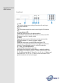
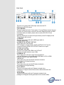
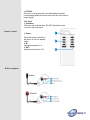
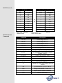
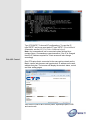
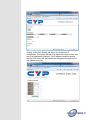
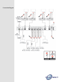
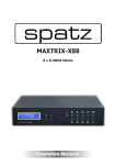
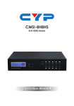
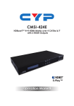
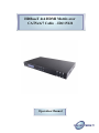
HDBaseT 4x4 HDMI Matrix over
CAT5e/6/7 Cable - ID# 15121
Operation Manual
Introduction
The 4x4 HDMI Matrix over 4 CAT5e/6/7 with 2 HDMI outputs supports
resolutions up to 1080p Full HD and 1920x1200@60Hz with multichannel
digital audio from up to four high definition sources to up to four CAT5e/6/7
output and 2 HDMI synchronized with 2 CAT5e/6/7 output ports. It supports
digital audio formats such as LPCM 7.1CH, Dolby TrueHD, Dolby Digital Plus
and DTS-HD Master Audio. Also, 3D content can be displayed when
connecting a 3DTV and 3D source. The Matrix allows the connection of
source equipment to output displays, over distances of up to 60 meters along
with IR and RS-232(includes telnet) control.
Features
•
•
•
•
•
•
•
•
•
•
•
•
HDMI, HDCP1.1 and DVI compliant
Supports HDMI 3D features
Supports resolutions to VGA ~ WUXGA and 480i~1080p follow by
output display’s EDID settings
Supports extension up to 60 meters through CAT5e/6/7
Supports 3D signal display follow by display TV’s EDID
Supports simultaneous HDMI output display on A and C CAT5e/6/7
output
Supports HDMI input up to 15 meters with 8bits resolution or 10
meters with 12bits resolution
Supports IR in/out from input and output locations
Supports RS-232 (include Telnet), remote control and on panel
controls
1U size design
Supports external and internal EDID setting
Supports LPCM 7.1CH, Dolby TrueHD, Dolby Digital Plus & DTS-HD
Master Audio transmission
Applications
•
•
•
•
•
•
HDMI System controls
Video/TV wall display and control
Security surveillance and control
Commercial advertising, displaying and control
Lecture room display and control
Hyper market demonstration and control
System Requirements
•
•
•
•
Input source equipments with HDMI connection cables
Industry CAT5e/6/7 cable.
HDMI over CAT5e/6/7 receivers with industrial CAT5e/6/7 cables
Output displays or audio receiver equipments with HDMI connection
cables.
Operation Controls
and Functions
Front Panel
1. LCM:
This monitor displays your setting information with each input
and output selection.
2. IR:
This IR window accepts the remote control signal of this device
only.
3. Power button LED:
Press this button to turn on the device and the
green LED will illuminate when the power is on. When the LED
illuminate in red it is in standby mode
4. LOCK:
Press this button to lock all the buttons on the panel and the
LED will illuminate. To unlock, just press it again.
5. Menu:
Press this button once to select EDID setting from STD
(internal) 1 or TV (external) 2 then press it again to confirm the
selection. Press this button every to confirm the selection.
6. 1 ~4 /A ~ D & OUT/IN button:
Press OUT/IN button first to select the
output/input then press the number button to make the selection
accordingly. For example, output A ~ B wish to select input 1 and
C ~ D wish to select input 2. Press Out →A→B →In→1→Menu, and
then press Out →C→D→In→2→Menu. If the menu button is not
press the selection will not be changed.
Back Panel
1. RS-232:
This slot is to connect with D-Sub 9pin cable from the PC/
NB device for RS-232 control.
2. IP CONTROL:
This port is also the link for Telnet system. For non Ethernet version this port
is the link for Telnet control, connect to an active Ethernet link with an RJ45
terminated cable (for details, please refer to section RS-232 & Telnet
commands).
Warning: Please do not connect this port directly to the PC/Laptop as the
Telnet function will not work
3. SERVICE:
This slot is to connect with mini USB B type cable for
firmware update only.
4. HDMI OUT & CAT5e/6/7 OUT A/C:
These slots are to connect with
HD TV/display for instant display. And the CAT5e/6/7 OUT can be
connected from the HDMI over CAT5e/6/7 Receiver for signal
extension up to 100m.
5. CAT5e/6/7 OUT B/D:
This slot is to connect with HDMI over CAT5e/67
Receiver for signal extension up to 100m.
6. HDMI IN 1~4:
These slots are to connect to input source equipment
such as DVD player or Set-Up-Box with HDMI cable or DVI to HDMI
converter cable for input signal sending.
7. IR IN 1~4:
These slots are to connect with IR extender included in
the package for IR signal receiving.
8. IR OUT 1~4:
These slots are to connect with IR blaster included in
the package for IR signal sending.
9. ALL IR OUT:
This slot is to connect with the IR blaster included in the
package for IR signal received from receiver sides and send to the
source side.
10. ALL IR IN:
This slot is to connect with the IR extender included in the
package for IR signal receiving and send out to receiver sides.
11. DC24V:
This slot is to plug the power cord with adaptor included
in the package and then connect them with AC wall outlet for
power supply.
Side Panel
1. Ventilator:
These are fan ventilator area, DO NOT block these area
or cover it with any object.
Remote Control
1. Power:
Press this button to switch on
the device or set it to standby
mode.
2. IN:
Input ports selection 1~4.
3. OUT:
Output ports selection A~D.
IR Pin Assignment
RS-232 Protocols
#ID 15120
Remote Control Console
PIN
Assignment
PIN
Assignment
1
NC
1
NC
2
Tx
2
Rx
3
Rx
3
Tx
4
NC
►
4
NC
5
GND
◄
5
GND
6
NC
6
NC
7
NC
7
NC
8
NC
8
NC
9
NC
9
NC
Baud Rate: 19200bps
Data bit: 8 bits
Parity: None
Flow Control: None
Stop Bit: 1
RS-232 & Telnet
Commands
Command
Description
A1~A4
Switch output A to 1~4
B1~B4
Switch output B to 1~4
C1~C4
Switch output C to 1~4
D1~D4
Switch output D to 1~4
AB... 1~CD...4
Switch output ABCD... to 1~4
SETIP<IP><SubNet><GW>
Setting IP. SubNet. GateWay (Static IP)
RSTIP
IP Configuration Was Reset to Factory
Defaults <DHCP>
IPCONFIG
Display the current IP config
P0
POWER OFF
P1
POWER ON
I1~I4
switch all the output to 1~4
ST
Display the current matrix status and F/W
version
RS
System Reset to A1, B2, C3 & D4
EM
Setting EDID MODE. 1-STD 2-TV
?
Display all the available commands
Quit
Exit (for telnet only)
Note: All the commands will not be executed unless followed with a
carriage return. All letters are case-insensitive.
Telnet Control
Before attempting to use the telnet control, please ensure that both
the Matrix (via the 'LAN /CONTROL' port) and the PC/Laptop are
connected to the active networks.
To access the telnet control in Windows 7, click on the 'Start' menu
and type "cmd" in the Search field then press enter.
Under Windows XP go to the 'Start' menu and click on "Run", type
"cmd" with then press enter.
Under Mac OS X, go to Go→Applications→Utilities→Terminal
See below for reference.
Once in the command line interface (CLI) type "telnet", then the IP
address of the unit and "23", then hit enter.
Note: The IP address of the Matrix can be displayed on the device's
LCM monitor by pressing the Menu button twice.
This will bring us into the device which we wish to control. Type "HELP"
to list the available commands.
Type “IPCONFIG” To show all IP configurations. To reset the IP,
type “RSTIP” and to use a set static IP, type ”SETIP” (For a full list of
commands, see the RS-232 & Telnet Commands above).
Note: Any commands will not be executed unless followed by a
carriage return. Commands are case-insensitive. If the IP is changed
then the IP Address required for Telnet access will also change
accordingly
Web GUI Control
On a PC/Laptop that is connected to the same active network as the
Matrix, open a web browser and type device's IP address on the web
address entry bar. The browser will display the device's status, control
and User setting pages.
Click on the 'Control' tab to control power, input/output ports, EDID
and reset mode
Clicking on the 'User Setting' tab allows you to reset the IP
configuration. The system will ask for a reboot of the device every time
any of the settings are changed. The IP address needed to access
the Web GUI control will also need to be changed accordingly on the
web address entry bar.
Connection Diagram
Specifications
Video Bandwidth
Input Ports
Output Ports
Power Supply
ESD Protection
225 MHz/6.75 Gbps
4 x HDMI,
5 x IR Extender,
1 x Control
1 x RS-232,
1 x Mini USB B type(for firmware update
only)
4 x CAT5e/6/7, 2 x HDMI, 5 x IR Blaster
24V/2.7A DC (US/EU standards,CE/FCC/
UL certified)
Dimensions
Weight
Chassis Material
Color
Operating Temperature
Storage Temperature
Power Consumption
Human body model:
±8kV (air-gap discharge)
±4kV (contact discharge)
436mm(W) x 255mm(D) x 48mm(H)
3372 g
Metal
Black
0 ̊C ~ 40 ̊C/32 ̊F ~ 104 ̊F
−20 ̊C ~ 60 ̊C / −4 ̊F ~ 140 ̊F
20 ~ 90 % RH (non-condensing
Relative Humidity
40W