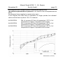
1
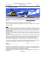
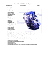
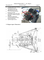
Manual
Smart M 160/1
Engine
Manufacturer: Ecofly GmbH, Germany
November 05
Manual Smart M160 / 1– UL- Engine
Ecofly GmbH
Page 0
Table of Contents
1.
2.
3.
4.
5.
6.
7.
Technical Concept .................................................................... 1
1.1.
Description....................................................................... 2
1.2.
Engine Layout / Dimensions .............................................. 3
Technical Data ......................................................................... 5
2.1.
Technical Data / Key Features ........................................... 5
2.2.
Performance and Torque Curve for 60KW Engine............... 6
2.3.
Performance and Torque Curve for 74KW Engine............... 7
2.4.
Fuels / Fuel System .......................................................... 8
2.5.
Lubricants ........................................................................ 9
2.6.
Cooling System / Coolant .................................................10
2.7.
Manifold Intake ................................................................10
2.8.
Propeller Gear .................................................................10
Operating Limits ......................................................................11
3.1.
Water / Oil.......................................................................11
3.2.
Height .............................................................................13
3.3.
Manifold Temperature ......................................................13
3.4.
Manifold Pressure............................................................13
3.5.
ECU / Relay Box..............................................................14
Engine Operation.....................................................................14
4.1.
Ignition / Warming-up .......................................................14
4.2.
Takeoff............................................................................15
4.3.
Flight ..............................................................................15
4.4.
Landing ...........................................................................15
4.5.
Switching off....................................................................15
Checks....................................................................................16
5.1.
Daily Checks ...................................................................16
5.2.
Checks after first 25hrs (in addition to 5.1.)........................16
5.3.
Checks after 100hrs / 1 year (in addition to 5.1.) ................16
5.4.
Checks after 300hrs / 3 years (in addition to 5.1. & 5.3.).....17
5.5.
Checks after 1500hrs or 15 years .....................................17
Maintenance............................................................................17
6.1.
Oil Circuit ........................................................................17
6.2.
Air intake / Air filter (Oil in intake system?).........................17
6.3.
Compression...................................................................17
6.4.
Spark Plugs .....................................................................17
6.5.
Belt Tension ....................................................................17
6.6.
Extending Engine Life ......................................................17
6.7.
Torque Table ...................................................................18
Document Version History ........................................................18
November 05
1.
Manual Smart M160 / 1– UL- Engine
Ecofly GmbH
page 1
Technical Concept
Our engine is a series-produced automobile engine from the smart car with belt
drive for use as a stationary engine or as an uncertified power train for sports
aircraft.
Engine RPM is reduced with the help of a toothed belt drive.
Car-like vibration damping is achieved by using a centrifugal clutch with soft
torsion coupling.
Note:
Since this engine is a variant of a serially produced stationary engine, it does not
meet the safety requirements of certified aircraft engines. The engine may
therefore only be used in aircraft types where sudden engine failure does not
endanger safety.
This means that the glide and landing characteristics of the aircraft must not be
affected by engine failure, proof of which must be produced during aircraft
certification.
Therefore, aircraft equipped with this engine must only be flown over such
terrain and at altitudes and speeds so that in the event of sudden engine failure,
safe landing is always possible, responsibility for which rests with the pilot.
Local regulations may apply. For Germany, see Civil Aviation Act (Luft VO) § 6.
The user acknowledges by signing below that engine failure is possible at any
time because the engine is used for a purpose other than designed.
Place.........................................
Date:....................................
Signature:..................................................................................................
Furthermore, any modifications to the engine and/or drive pose potential safety
risks. As such, distributors are advised to not undertake any changes prior to
qualified engineering analysis and exhaustive testing!
Any irregularities, anomalies and damage must be immediately reported to the
distributor!
Signature:....................................................
November 05
Manual Smart M160 / 1– UL- Engine
Ecofly GmbH
page 2
1.1. Description
o
o
o
o
o
o
o
o
o
o
o
o
o
o
o
o
o
3-cylinder series
engine with
turbocharger;
60KW / 74KW
Fully electronic
sequential
injection
Lambda sensor
controlled 3-way
catalytic
converter
integrated into
muffler (optional)
Electronic knock
control using
knock sensor
Power control
using redundant
potentiometer
and e-gas
Dual ignition for maximum smoothness (single-circuit)
Manifold pressure controlled by variable valve timing, intercooler
Water-cooled turbocharger housing with pressurised lubrication
Thermostat-controlled water cooling
Oil circuit with wet sump
Overhead camshaft with maintenance-free chain drive
Maintenance-free valve control with hydraulic valve-play compensators
All-aluminium crankcase
Belt-driven water pump and alternator
Electrical starter
Electrical fuel pump
Electronic engine control unit (ECU) with relays and 2 sets of cables
November 05
o
o
o
o
o
o
Manual Smart M160 / 1– UL- Engine
Ecofly GmbH
Flanged gearbox with bearingmounted drive shaft
Toothed belt drive with
adjustable belt tension
CNC machined propeller
bearing and shaft
Centrifugal clutch with metal
bushings to reduce torsional
vibration
Elastically suspended
mounting plate for sensors ,
relay box and ECU
4-point engine mount
1.2. Engine Layout / Dimensions
page 3
November 05
Manual Smart M160 / 1– UL- Engine
Ecofly GmbH
page 4
November 05
2.
Manual Smart M160 / 1– UL- Engine
Ecofly GmbH
page 5
Technical Data
2.1. Technical Data / Key Features
60 KW
Capacity (cm³)
Stroke / Bore (mm)
Compression ratio
Cylinders / Valves
Spark plugs (per cylinder)
Engine weight per DIN (kg)
Max. torque (Nm)
Max. power output (kW)
Max. continuous RPM
Max. short-time RPM
Max. manifold pressure (bar)
Charge air control
Oil pump
Ventilation
Fuel injection / injection
pressure
Fuel
Lambda sensor
Anti-knock control
Max. permissible
turbocharger RPM
Max. exhaust temperature
Engine Diagnostics
74 KW
698
68 / 66
9.5 (-0.4) : 1
3 cylinders; 2 valves per cylinder
2
57
110 at
130 at
2000 – 4750 RPM
2500 – 5300 RPM
60 at 5250 RPM
74 at 5600 RPM
(continuous running)
(continuous running)
5800 RPM
6000 RPM
0.9 (+ 0.1 / - 0.2)
1.3 (+ 0.1 / - 0.1)
Map-guided
Chain-driven, external gear pump; wet sump
Integrated full and partial load ventilation
Bosch EV6 / 3.8 bar via intake manifold
(max. 4.8 bar)
Min. RON 95 (super unleaded)
Bosch LSF4
Electronic, adaptive; 1 knock sensor
240 000
950°C (at turbocharger inlet),
short-time 980°C
Diagnostics module to read stored errors
November 05
Manual Smart M160 / 1– UL- Engine
Ecofly GmbH
2.2. Performance and Torque Curve for 60KW Engine
page 6
November 05
Manual Smart M160 / 1– UL- Engine
Ecofly GmbH
2.3. Performance and Torque Curve for 74KW Engine
page 7
November 05
Manual Smart M160 / 1– UL- Engine
Ecofly GmbH
page 8
2.4. Fuels / Fuel System
Use only unleaded, min. 95 octane fuel (unleaded Super = standard automotive
fuel). Do not use any fuel additives !
Remarks :
o Leaded fuels damage not only the catalytic converter but also the lambda
sensor! The general rule also for engines not fitted with a catalytic converter
is therefore: do not use leaded fuel!
o In case only Normal unleaded fuel is available, it can be used in exceptional
cases provided maximum power is reduced to 80% (the knock control
system automatically adjusts the ignition angle, minimising the risk of
engine damage).
o Recommended optionally:
o Unleaded Super – Plus (RON 98); at very high ambient
temperatures and limited cooling of charge air, this fuel grade might
even result in slightly higher performance.
o We also recommend sulphur-free fuels such as Shell Optimax
(RON 99) (very environment-friendly and extremely knock-resistant)
o All other fuels, even aviation-grade fuels will cause irreparable damage to
the engine sooner or later!
o Injection valves are susceptible to clogging due to fuel impurities , so use
only filtered fuel and check/replace fuel filter at regular intervals.
o A noisy fuel pump may be indicative of a clogged fuel filter: replace fuel
filter!
o Take special care when working with or checking the fuel system.
o Guide all fuel lines away from heat sources so as to protect them from
thermal fatigue. Insulate fuel lines against heat where necessary.
November 05
Manual Smart M160 / 1– UL- Engine
Ecofly GmbH
page 9
2.5. Lubricants
The oil tank has a capacity of about 3.2l.
Replace the oil filter when changing the oil. Use suction to withdraw spent oil
completely.
Ecofly will install an oil bleed screw upon request.
The difference between the maximum and minimum oil level amounts to about
0.5l.
Note: While topping up oil, ensure that the oil level NEVER exceeds the
max. level indicated on the dip stick.
Withdraw excess oil by suction if necessary.
The air-exhaust system of this engine is sensitive to excess oil; excessive oil
levels may even result in irreparable damage to the engine!
Minimum requirements :
Use only branded oils of API grade “SG” and higher.
Recommended:
Semi-synthetic or synthetic oils are recommended.
The best oils currently on the market are classified “SJ” (API).
The best oil you can use for this engine will meet the current Mercedes -Benz
Specification 229.3 (includes 229.1).
We cite an excerpt from MB Specification 229.3:
The viscosity class must be
selected according to the
temperature range:
15W – 40 should usually be
adequate for most
applications .
November 05
Manual Smart M160 / 1– UL- Engine
Ecofly GmbH
page 10
2.6. Cooling System / Coolant
The coolant is a 50:50 mixture of water and antifreeze/anticorrosive fluid.
A 50:50 mixture provides frost protection down to -37°C.
At temperatures as low as -45°C, increase the ratio of the antifreeze
/anticorrosive fluid to 55% but not higher, since otherwise heat drain will be
impeded.
Use only antifreeze/anticorrosive fluids recommended by Mercedes -Benz. For
further information, contact the nearest Mercedes -Benz or smart service station.
In the event of coolant loss, determine cause, correct and refill as necessary. At
the time of refilling, top up with the recommended ratio of water and antifreeze/anticorrosive fluid.
Completely replace the coolant every 2 years.
Since coolant temperature is thermostatically controlled, do not cover the cooler
in winter!
2.7. Manifold Intake
Ensure that the air taken in is as cool as possible.
If necessary, take special measures to ensure that air taken in is not
inadvertently preheated by the cooler or the exhaust.
Since carburettor icing cannot occur in this engine by design (being an injection
system) preheated air is not merely superfluous, it actually reduces engine
performance!
If the intake temperature is too high, the ECU will automatically reduce engine
power output, WHICH MAY GIVE RISE TO DANGEROUS SITUATIONS.
Use only suitable air filters. Check, clean or replace the air filter at regular
intervals.
Ensure that all water entering the air intake is drained completely ahead of the
air filter.
Ensure that no rubber particles from the belt drive are sucked in.
Optimum charge air cooling must be ensured whenever the engine is
operational. NEVER cover the intercooler fully or even partially in winter.
2.8. Propeller Gear
The transmission ratio is 2.1 : 1.
Toothed belt: HTD-(Powergrip GT2) 8M; 60mm width.
Check belt tension at regular intervals. When the engine is cold, the belt should
yield 5-10mm when pressed down at the centre of the exposed length.
If necessary, insert washers to adjust the distance of the propeller axle from the
drive shaft.
November 05
Manual Smart M160 / 1– UL- Engine
Ecofly GmbH
page 11
Note:
o Ensure that the drive axes are perfectly parallel.
o Misalignments will provoke damage
o NEVER assemble the propeller axle without locating pins .
o Do not insert any spacers to extend the engine-propeller distance: this will
increase the bending load on the gears beyond permissible limits !
Note that a new belt will initially lose some rubber; this is not indicative of
unusual wear.
Check for play on the bottom bearing by pressing the belt down with a finger (in
case of damage, the play can be felt).
The same applies to the front and rear propeller bearings. Push against the
propeller to check that there is no radial play.
To increase comfort, the engine is fitted with a centrifugal clutch (which engages
at 1600 – 2000 RPM) and a soft, metal torsion coupling.
Never get out of an aircraft when the engine is idling, not even when the
propeller has stopped turning! Always switch off the engine before getting
out of the cockpit!
3.
Operating Limits
While the engine is rated for maximum power output of 60/74KW, we
recommend that the engine power is suitably adjusted for cruise flight to
conserve fuel.
Note that the engine is completely unsuited for aerobatic manoeuvres! Do not
conduct stall exercises!
Aerobatic manoeuvres will damage the engine!
Avoid any critical RPM at which the natural frequency of the propeller and
cockpit cell resonate.
Maximum permissible engine rating amounts to 5800 RPM.
3.1. Water / Oil
Maximum permissible water temperature is 105°C.
Water temperature of 110°C is permissible for short times.
If the water temperature increases, the ECU will automatically reduce engine
power output.
Minimum water temperature for takeoff amounts to 60°C.
Maximum permissible oil temperature is 140°C.
Oil temperature of 150°C is permissible for short times.
Minimum oil temperature for takeoff amounts to 60°C.
November 05
Manual Smart M160 / 1– UL- Engine
Ecofly GmbH
page 12
The diagram below indicates normal temperatures against RPM.
The minimum permissible oil pressure is a function of the oil temperature and
RPM.
See diagram below (applies to engines when new)
In the engines that have been in operation for longer periods, the indicated
values can be lower by about 10%. For instance:
At 2000 RPM:
At 4000 RPM:
At 5500 RPM:
Min. oil pressure 2.0 bar (oil temperature 110°C); if oil
temperature is higher, oil pressure will be lower
Min. oil pressure 2.9 bar (oil temperature 125°C); if oil
temperature is higher, oil pressure will be lower
Min. oil pressure 3.3 bar (oil temperature 135°C); if oil
temperature is higher, oil pressure will be lower
November 05
Manual Smart M160 / 1– UL- Engine
Ecofly GmbH
page 13
3.2. Height
The turbocharger is configured such that the engine will deliver 60/74KW of
power up to 2500m height.
Reduce power setting above 2400m so that the turbocharger does not
exceed its maximum rotational speed.
As a thumb rule:
Reduce power by 50 RPM (i.e. by about 1%) for every 100m increase in height
above 2400m. For example, at 3000m, reduce power by 300 RPM (6*50=300).
We recommend that you reduce the RPM even further above a certain height.
3.3. Manifold Temperature
Maximum permissible manifold temperature is 45°C at 20°C ambient
temperature.
The lower the manifold temperature, the better will be engine performance due
to the more favourable ignition angle and higher air density.
Engine power output is lower at 45–55°C while at 60°C, the ECU will sharply
lower manifold pressure!
Use Super Plus (98 RON) fuel at very high ambient temperatures to prevent the
anti-knocking system from scaling back ignition.
If necessary, use an electric fan to support cooling (in cases where air flow is
poor, e.g. in trike applications).
In general, allow uniform air flow on the surface of the intercooler!
3.4. Manifold Pressure
Manifold pressure at full power setting must show between 0.7 and 1.0 bar (60
KW) or 1.2 and 1.4 bar (74 KW).
The SMART-MIP (engine monitoring unit) which shows total pressure, will
indicate at full load 1.7 to 2 bar (60 KW) and 2.2 to 2.4 bar (74 KW).
If pressure is not high enough, check system for leaks. If no obvious faults are
found, contact the service centre and have the turbocharger recalibrated.
If the manifold pressure exceeds 1.0 bar (60 KW) or 1.4 bar (74 KW), contact
the service centre and have the turbocharger recalibrated.
November 05
Manual Smart M160 / 1– UL- Engine
Ecofly GmbH
page 14
3.5. ECU / Relay Box
Install the ECU so that the rear of the ECU is ventilated by cool ambient air. This
arrangement is necessary to drain the heat from active components .
Max. temperature on ECU housing: 90°C.
Install the relay box and contacts such that they are protected from spray.
Moisture will cause contact problems!
4.
Engine Operation
Read the manual before operating the engine!
Note:
Always adjust engine RPM so that the engine runs smoothly.
Make sure that the centrifugal clutch does not “drag”. Avoid the 4100-4200 RPM
range as engine operation is not as smooth as at other speeds.
4.1. Ignition / Warming-up
Complete the daily check (see 5.1) before switching on the engine.
To start engine:
Fuel valve:
Open
Throttle:
Idle position (fuel/air mixture is controlled electronically)
Main switch:
On
Ignition:
On
Starter:
Operate
As soon as the engine starts, throttle up sufficiently so that the engine runs
smoothly in conjunction with the resonance frequency of the cell/propeller.
Never operate the engine for long periods at low RPM (with stationary
propeller) so as to provoke overheating situations.
If water temperature touches 100°C on ground, increase engine RPM to
2000 for better cooling!
Allow engine to warm up at about 2000 RPM.
After 2 minutes, engine RPM can be raised to 2500 RPM until all temperatures
have reached minimum operating temperatures (water: min. 60°C, oil min 60°C).
After taxying to the holding point, apply brakes and set the engine briefly to full
power. Check that manifold pressure increases to between 0.7-1 bar (60 KW) or
1.2 to 1.4 bar (74 KW). The SMART-MIP will indicate total pressure, so at the
time of this check, it should indicate 1.7 to 2 bar (60 KW) or 2.2 to 2.4 bar (74
KW).
If manifold pressure does not increase, abort takeoff immediately,
determine the cause of the fault and correct.
Monitor oil pressure at all times .
November 05
Manual Smart M160 / 1– UL- Engine
Ecofly GmbH
page 15
4.2. Takeoff
Always set full power for takeoff.
In addition to observing temperatures, monitor especially the indicated oil and
manifold pressure.
Leave engine at full power until you reach safe flying altitude; since the engine
regulates itself, it is not necessary to power down!
4.3. Flight
Set the desired engine RPM in flight, taking care to avoid as far as possible,
RPM ranges where engine running is not smooth.
Several sensors report engine status to the electronic controller for optimum
engine operation. If any critical value is exceeded, then the electronic controller
reacts by reducing power in order to protect the engine. In extreme cases, e.g. if
the ignition cable breaks, the electronic controller may even shut off the engine.
In such a case:
o Switch ignition OFF (to reset the engine controller)
o Switch ignition ON again
o Start engine
In the case of such a rare event, an engine diagnostics device must be used on
the ground to read, identify and correct the fault.
4.4. Landing
Set engine speed to 2000 RPM during landing approach. The centrifugal clutch
is fully engaged at this speed and the propeller will show better retarding
characteristics .
4.5. Switching off
After landing and taxi in, all engine components would have cooled down
sufficiently so that the engine can be switched off without taking any special
measures.
The turbocharger has a self-regulating thermosyphon to cool the exhaust
manifold in order to prevent oil coking.
After stationary full-load operation, it is sensible to allow the engine to run for
two minutes (with propeller engaged at about 2000 RPM) to allow it to cool
down.
November 05
5.
Manual Smart M160 / 1– UL- Engine
Ecofly GmbH
page 16
Checks
5.1. Daily Checks
o
o
o
o
o
o
o
o
o
o
Remove cowling completely (top and bottom halves )
Check engine frame and bearing seats (gearbox) for cracks
Check bearing washers for cracks, replace if necessary
Turn the drive belt around once and check for damage (outside and inside)
Check drive and coolant lines as well as connections for coolant loss;
correct as necessary
Check drive for oil leaks ; correct all leaks immediately
Ensure that oil level is between Min. and Max. markings on the dip stick; top
up oil if necessary. DO NOT OVERFILL!
Check fuel system for leaks
Check all cables for abrasion damage; check proper seating of plugs
Check proper functioning of the centrifugal clutch
(Clutch should engage at 1800 ± 200 RPM)
5.2. Checks after first 25hrs (in addition to 5.1.)
o
o
o
o
o
Check the entire power train for loose or missing nuts and screws. Replace
or tighten as necessary.
Check belt, belt tension, propeller drive and propeller bearings
Check air filter
Change oil, renew oil filter
Clean and renew fuel filter if necessary
5.3. Checks after 100hrs / 1 year (in addition to 5.1.)
o
o
o
o
o
o
o
o
o
Check the entire power train for loose or missing nuts and screws. Replace
or tighten as necessary
Coat engine bearing and other rubber components with a rubber-care fluid
Check belt, belt tension, propeller drive and propeller bearings
Check belt tension: must yield 5-10mm in a cold engine when pressed
down with a finger; adjust if necessary
Change oil, renew oil filter
Renew fuel filter
Carefully check fuel system and lines for signs of brittleness; check all
guides, joints and connectors, renew ageing components where necessary
Clean air filter; renew if necessary
Check for dirt in the interstices between cooling fins of the intercooler, clean
carefully
November 05
Manual Smart M160 / 1– UL- Engine
Ecofly GmbH
page 17
5.4. Checks after 300hrs / 3 years (in addition to 5.1. & 5.3.)
o
o
o
o
o
Renew spark plugs
Check compression
Renew coolant
Until and such time long-term tests are concluded, we strongly recommend
renewing the belt to be on the safe side.
Contact Ecofly GmbH.
after completion of long-term tests we expect a renewal of the belt every
600h (check in advance with Ecofly GmbH)
5.5. Checks after 1500hrs or 15 years
We recommend full engine overhaul after 1500hrs. Contact your engine service
station.
Since these engines are produced in large numbers, it may be cheaper to buy a
new engine (crankcase with power plant and cylinder head) and install it along
with a new e-gas unit and turbocharger.
If the belt pulleys are not severely damaged, you will only need to replace three
bearings in the gearbox.
6.
Maintenance
Contact Ecofly GmbH until long-term tests are concluded. If necessary, detailed
maintenance instructions can be obtained from any smart-center website.
6.1. Oil Circuit
In process
6.2. Air intake / Air filter (Oil in intake system?)
In process
6.3. Compression
In process
6.4. Spark Plugs
In process
6.5. Belt Tension
In process
6.6. Extending Engine Life
In process
November 05
Manual Smart M160 / 1– UL- Engine
Ecofly GmbH
page 18
6.7. Torque Table
All M6 in aluminium:
All M8 in aluminium:
Engine frame strut to cylinder head:
Alternator to aggregate frame:
Starter to crankcase / gearbox:
Mitnehmerscheibe to crankshaft (M10*1):
LU Turbocharger to cylinder head (stud):
LU Turbocharger to cylinder head (M6 nut):
Lambda sensor in turbocharger housing:
Knock-sensor to crankcase:
Fuel distributor on manifold (M6):
Pressure sensor on manifold:
E-Gas Drosselklappensteller an Saugrohr:
Oil line to Turbo (screw M8 * 1):
Water line to turbocharger (M12.5 * 1.5):
Spark plugs :
Drive wheel to crankshaft extension:
Slotted nut: drive wheel to propeller shaft:
7.
12 ± 1 Nm
20 ± 1,6 Nm
23 ± 2 Nm
28 ± 2 Nm
20 ± 1,6 Nm
47Nm ± 2Nm, angle of twist 90°
6 Nm ± 0,5 Nm
16 Nm ± 1 Nm
50 Nm ± 5 Nm
20 Nm ± 1,6 Nm
8,5 Nm ± 0,5 Nm
5,5 Nm ± 0,5 Nm
8,5 Nm ± 0,5 Nm
10 Nm ± 1 Nm
19 Nm ± 1 Nm
20 Nm ± 2 Nm
180 Nm + 20 Nm
200 Nm + 20 Nm
Document Version History
The current version of this document can be downloaded from www.ecofly.de.
First edition English version July 2005
Second edition English version November 2005