1
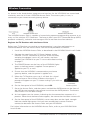
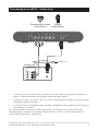
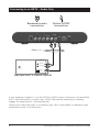
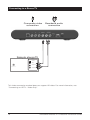
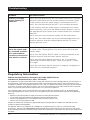
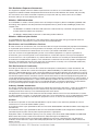
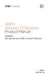
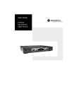
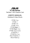
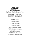
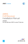
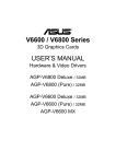
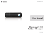
VIP2502W
Wireless IPTV Receiver
Installation Guide
TO REDUCE RISK OF ELECTRIC SHOCK,
DO NOT REMOVE COVER (OR BACK). NO
USER-SERVICEABLE PARTS INSIDE.
REFER SERVICING TO QUALIFIED SERVICE
PERSONNEL.
CAUTION
RISK OF ELECTRIC SHOCK
DO NOT OPEN
Graphical symbols and supplemental warning markings are located on the back and bottom
of the terminal.
WARNING
TO REDUCE THE RISK OF FIRE OR SHOCK, DO NOT EXPOSE THIS APPLIANCE TO RAIN
OR MOISTURE.
The lightning flash with arrowhead symbol within an equilateral triangle
is intended to alert the user to the presence of uninsulated dangerous
voltage within the product’s enclosure that may be of sufficient
magnitude to constitute a risk of electric shock to persons.
The exclamation point within an equilateral triangle is intended to alert
the user to the presence of important operating and maintenance
(servicing) instructions in the literature accompanying the appliance.
Product identification and supply rating are provided on the label found
on the bottom of the unit.
IMPORTANT SAFETY INSTRUCTIONS
•
Read these instructions.
•
Keep these instructions.
•
Heed all warnings.
•
Follow all instructions.
•
Do not use this apparatus near water.
•
Clean only with a dry cloth.
•
Do not block any ventilation openings. Install according to the manufacturer’s
instructions.
•
Do not install near any heat sources, such as radiators, heat registers, stoves, or other
apparatus (including amplifiers) that produce heat.
•
Protect the power cord from being walked on or pinched, particularly at plugs,
convenience receptacles, and the point where they exit from the apparatus.
•
Only use attachments/accessories specified by the manufacturer.
•
Unplug this apparatus during lightning storms or when unused for long periods of
time.
•
Refer all servicing to qualified service personnel. Servicing is required when the
apparatus has been damaged in any way, such as the power supply cord or plug
is damaged, liquid has been spilled or objects have fallen into the apparatus, the
apparatus has been exposed to rain or moisture, does not operate normally, or has
been dropped.
ii
VIP2502W Wireless IPTV Receiver Installation Guide
Follow these important safety guidelines when positioning and connecting your wireless
receiver:
•
Do not block the slots and openings
•
Do not place anything on top of the wireless receiver
•
Do not position the wireless receiver in a confined space, such as an enclosed
cabinet, that does not provide adequate ventilation.
•
Do not position the wireless receiver near any external heat source that could
raise the temperature around the unit. Do not place the wireless receiver on top
of another heat producing electronic device.
•
Allow for adequate ventilation around the wireless receiver to maintain normal
operating temperature. Do not place it in a sealed enclosure without providing
for adequate airflow.
•
Use only the power adapter and cord supplied to connect the VIP2502W to your
home AC power outlet.
•
Do not plug the AC power adapter into a switched power outlet.
•
Always transport the receiver in its original factory carton, or in an equally well-padded
container.
•
Whether installed or being transported, do not expose the receiver to temperature
extremes. The temperature range for operation is from 0° to +40°C. The non-operating
(transport or storage) temperature range is from -40° to +60°C.
•
If the wireless receiver is used outdoors (patio, balcony, etc.), it should be protected
from moisture, temperature extremes, and from prolonged exposure to direct
sunlight, any of which could cause damage. Note also that adequate ventilation must
be maintained, even if the wireless receiver is operated outdoors.
This manual includes the manufacturer’s recommended safeguards and all the information
needed to connect your receiver to both your in-home IP network and your entertainment
system. The safety and installation information was developed and provided primarily by
the receiver manufacturer, Motorola Mobility, LLC.
VIP2502W Wireless IPTV Receiver Installation Guide
iii
Contents
Introduction . . . . . . . . . . . . . . . . . . . . . . . . . . . . . . . . . . . . . . . . . . . . . . 1
Overview . . . . . . . . . . . . . . . . . . . . . . . . . . . . . . . . . . . . . . . . . . . . . . . . 2
Front Panel . . . . . . . . . . . . . . . . . . . . . . . . . . . . . . . . . . . . . . . . . . . . . . . 2
Rear Panel . . . . . . . . . . . . . . . . . . . . . . . . . . . . . . . . . . . . . . . . . . . . . . . 3
Wireless Connection . . . . . . . . . . . . . . . . . . . . . . . . . . . . . . . . . . . . . . . 4
Register the TV Receiver with the Access Point . . . . . . . . . . . . . . . . 4
Connecting Your TV Receiver . . . . . . . . . . . . . . . . . . . . . . . . . . . . . . . . . 5
Connection Options . . . . . . . . . . . . . . . . . . . . . . . . . . . . . . . . . . . . . 5
Common Cabling Examples . . . . . . . . . . . . . . . . . . . . . . . . . . . . . . . 6
Connecting to an HDTV – Video Only . . . . . . . . . . . . . . . . . . . . . . . . . . 7
Connecting to an HDTV – Audio Only . . . . . . . . . . . . . . . . . . . . . . . . . . 8
Connecting Audio to a Home Theater Receiver . . . . . . . . . . . . . . . . . . . 9
Connecting to a Stereo TV . . . . . . . . . . . . . . . . . . . . . . . . . . . . . . . . . . . 10
Troubleshooting . . . . . . . . . . . . . . . . . . . . . . . . . . . . . . . . . . . . . . . . . . . 11
iv
VIP2502W Wireless IPTV Receiver Installation Guide
Introduction
Congratulations on receiving your Motorola® VIP2502W Wireless IPTV Receiver.
The VIP2502W provides these extraordinary home entertainment features:
•
Wireless input via the VAP2500 Wireless Access Point lets you easily position or move
your video entertainment system anywhere in your residence -- or even outside -without network wires or cables
•
High Definition TV (HDTV), with up to twice the color resolution and up to six times
the sharpness of standard TV when connected to an HD-capable TV
•
A direct digital connection to consumer audio and video devices through multiple
interfaces
•
Video on Demand (VoD)
•
Commercial free, CD quality music
This installation manual introduces the basic features, outlines important safeguards, and
provides options for integrating your wireless receiver into your entertainment system.
Please take a few moments to read through this manual. Its configuration diagrams
and troubleshooting section will help you make the most of your home entertainment
experience.
Included in the carton:
•
VIP2502W Wireless High-Definition (HD) and Standard-Definition (SD) receiver
•
Power adapter and power cord
For more information about your TV service, refer to the other documentation from your
service provider.
VIP2502W Wireless IPTV Receiver Installation Guide
1
Overview
Front Panel
The illustration below and the table following it describe the front-panel features, controls
and indicator lights.
Key
Item
1
POWER
Function
Turns the Wireless Receiver on or off
If held for ten (10) seconds or longer, restarts the wireless
receiver
Lights green when the wireless receiver is on
2
2
USB
USB 2.0 connector
3
SIGNAL
QUALITY
4
LINK
5
HD
6
RECORD
7
MENU
Displays the VIP2502W menu on your TV screen
8
Up/Down
arrow keys
Changes the channel (channel up/channel down)
Left/Right
arrow keys
Use to navigate through on-screen program guide and menu
OK
center key
Use to select programs or accept menu options
The signal quality display lights green to indicate signal
strength from your wireless Access Point device. From one
to five bars are lit, depending on the strength of the received
signal. When signal strength is low the bar may display as
amber (weak) or red (unusable).
Lights green when receiving a video stream
Lights blue when receiving video resolution of 720p or 1080i
Lights red when a recording is in progress
VIP2502W Wireless IPTV Receiver Installation Guide
Overview
Rear Panel
The VIP2502W rear panel features are described in the following table.
Key
Item
1
NETWORK
2
Y
3
Pb
4
Pr
5
VIDEO OUT
6
L
R
Function
Ethernet 10/100Base-T RJ-45 port
RCA component video outputs to an HDTV
RCA standard-definition composite video output to a TV,
VCR, or other device
Left and right RCA stereo audio (analog) outputs
7
AUDIO OUT
8
OPTICAL
Toslink (S/PDIF) digital audio output
9
HDMI™
Connects to a High Definition TV or home theater receiver
with an HDMI input (for a DVI input, use an HDMI-to-DVI
adapter)
10
POWER
+12 VDC
Connector for the DC power adapter. Use only the adapter
specified for VIP2502W.
VIP2502W Wireless IPTV Receiver Installation Guide
3
Wireless Connection
As shown in the sketch below, programs and services for the VIP2502W are transmitted
wirelessly over the air from a VAP2500 Access Point. The access point, in turn, is
connected to your home network gateway device.
The VAP2500 Access Point is capable of transmitting separate programming streams to as
many as five wireless IPTV Receivers. The Access point uses Wi-Fi Protected Setup (WPS)
protocols to identify, authorize and manage traffic to and from the client devices.
Register the TV Receiver with the Access Point
Before your TV Receiver can receive any programming, it must be registered as an
authorized device with the Access Point. Run the WPS procedure as follows:
1. Install the VAP2500 Access Point as described in the VAP2500 Quick Install Guide.
2. Connect the cord from the DC Power Adapter to the
POWER +12VDC connector on the rear of the VIP2500,
and plug the adapter into an AC wall socket, and then
connect the VIP2502W to your TV set as described starting
on page 5.
3. The POWER button on the front of the VIP2502W lights
green to indicate power is applied. Ensure power is
applied to your TV, as well.
4. Ensure that the VAP2500 is connected to your home
gateway device, and that power is applied to it.
5. When the TV Receiver starts up, it will look for a signal
from an Access Point. When it detects the signal, a
prompt will appear on your TV screen asking if you wish to
connect.
6. On the front panel of the VIP2502W, touch OK.
VAP2500
Access point
7. Go to the Access Point, and then press and hold the WPS button on the front of
the VAP for two seconds, then release to activate the WPS process. The Access
Point’s WPS LED will blink orange.
8. An icon appears on the screen, indicating that the connection sequence is in
process. When three horizontal dots appear, the connection has been successful.
9. On the front panel of the VIP2502W, two or more bars on the signal strength
indicator should light green. You have now established a secure wireless
connection between the Access Point and your VIP2502W.
For further information on the VAP2500 Access Point, refer to your VAP2500 Quick
Install Guide.
4
VIP2502W Wireless IPTV Receiver Installation Guide
Connecting Your TV Receiver
This section describes alternative methods for connecting the VIP2502W to your home
entertainment system.
Instructions and diagrams are included for connections to:
•
High-Definition TV (HDTV)
•
Home Theater Receiver–Audio
•
Stereo TV
Before you move or change components on your entertainment system, always disconnect
power from the wireless receiver.
Connection Options
The VIP2502W offers the following video outputs:
HDTV
HDMI or Component video
Standard
Composite Video Out
To determine the available inputs on your TV, check the manual supplied with the TV or
on the TV itself. Use the following guidelines to determine the best connections for your
system. Use one of the following.
Connector
HDMI
HDMI
Description
HDMI offers higher video quality than component video. If your
HDTV has an HDMI input, use the HDMI connector.
HDMI provides both digital video and digital audio (including
Dolby® Digital 5.1 Surround Sound). No other connections are
necessary.
High-Definition
If your HDTV has a DVI input, you can use an HDMI-to-DVI
converter cable to connect to the VIP2502W HDMI connector.
Use a cable with an HDMI connector on one end and a DVI
connector on the other end. We do not recommend using an
HDMI-to-DVI or DVI-to-HDMI adapter. Because DVI does not
carry audio, a separate audio connection is required for a DVI
TV. If your TV has an optical S/PDIF audio connection, use the
OPTICAL connection. Otherwise, use the baseband AUDIO L
and R connections.
Component
Video
The Y Pb Pr connectors provide component video, the most
widely supported HDTV connection.
Component video provides a High-Definition analog video signal.
If your equipment supports an optical S/PDIF audio connection,
use the OPTICAL connection. Otherwise, use the baseband
AUDIO L and R connections.
VIP2502W Wireless IPTV Receiver Installation Guide
5
Connecting Your TV Receiver
Standard-Definition
Connector
Composite
Video
VIDEO
OUT
Description
To connect a Standard Definition TV, use the composite VIDEO
OUT connector.
Composite video provides a Standard-Definition analog video
signal. If your equipment supports an optical S/PDIF audio
connection, use the OPTICAL connection. Otherwise, use the
baseband AUDIO L and R connections.
Common Cabling Examples
The following cabling diagrams illustrate common sample audio/video (A/V) connections.
When connecting other components to your TV Receiver, refer to the other component
installation manuals for additional connection information.
6
VIP2502W Wireless IPTV Receiver Installation Guide
Connecting to an HDTV – Video Only
HDMI
Component video
connection
connection
HDMI
Either / or
Sample HDTV
Component
Video Input
HDMI
Y
Pb
Pr
CABLE/
ANTENNA IN
•
If your HDTV has an HDMI input, connect an HDMI cable to the HDMI connector as
shown. HDMI connection carries both video and audio signals.
•
If your HDTV has a DVI input, you can use an HDMI-to-DVI converter to connect to the
VIP2502W HDMI connector.
•
If your HDTV has component video, connect component video cables to the Y, Pb, and
Pr connectors as shown.
DVI and component video carry video signals only. To connect the audio, refer to the
following page. To connect to a home theater receiver, refer to “Connecting Audio to a
Home Theater Receiver – Audio Only.”
VIP2502W Wireless IPTV Receiver Installation Guide
7
Connecting to an HDTV – Audio Only
Baseband audio
connection
Optical S/PDIF
connection
HDMI
Either / or
INPUT
AUDIO LEFT
AUDIO RIGHT
CABLE/
ANTENNA IN
OPTICAL
SPDIF
Sample HDTV audio inputs
If your equipment supports it, use the OPTICAL S/PDIF output. Otherwise, use the AUDIO
OUT L and R connectors. In most cases, S/PDIF offers better audio quality, including
support for Dolby Digital 5.1 Surround Sound.
HDMI carries video and audio. If you connect your HDTV using HDMI, no additional audio
connections to the TV are necessary.
8
VIP2502W Wireless IPTV Receiver Installation Guide
Connecting Audio to a Home Theater Receiver
Baseband audio
connection
Optical S/PDIF
connection
HDMI
Either / or
AUDIO
R
L
VIDEO
VIDEO
S-VIDEO
DIGITAL INPUT
COAX
DVD
OPTICAL
CABLE/TV
VIDEO 2
TV/MONITOR
OUTPUT
SPEAKER
CONNECTORS
IN
VIDEO S-VIDEO
VCR
OUT
Sample home theater receiver
If your home theater receiver supports it, use the OPTICAL S/PDIF output. Otherwise,
use the AUDIO OUT L and R connectors. In most cases, S/PDIF offers better audio quality,
including support for Dolby Digital 5.1 Surround Sound.
VIP2502W Wireless IPTV Receiver Installation Guide
9
Connecting to a Stereo TV
Composite video
connection
Baseband audio
connection
HDMI
Sample stereoTV
INPUT
S-VIDEO
VIDEO
CABLE/
ANTENNA IN
AUDIO LEFT
AUDIO RIGHT
This video connection method does not support HD video. For more information, see
“Connecting an HDTV – Video Only.”
10
VIP2502W Wireless IPTV Receiver Installation Guide
Troubleshooting
Before calling your service provider, review this troubleshooting guide. If the suggestions
do not help you quickly solve a problem, contact your service provider.
Problem
Possible Solution
The wireless receiver
will not power on.
Verify that the power adapter is connected to the wireless
receiver and an AC outlet. Unplug the wireless receiver from
the outlet, plug it back in, and press the POWER button.
If the wireless receiver is connected to a switched outlet on a
wall or another unit, verify that the switch or unit is powered
on. Unplug the wireless receiver from the AC outlet, plug it
back in, and press the POWER button.
Press the POWER button on the wireless receiver front panel
instead of the remote control. The batteries in the remote
control may be depleted.
The remote control
does not work.
Verify that the TV is on.
Verify that the remote control is on STB mode.
Verify that there are no obstructions between the remote
control and the wireless receiver. Aim the remote control
directly at the wireless receiver front panel, not the TV or VCR.
The angle between the remote control and the wireless
receiver may be too large. Stand in front of the wireless
receiver and not too far to either side.
Press and release operation keys one at a time, firmly and
deliberately.
Try changing channels using the buttons on the wireless
receiver front panel.
Check the batteries in the remote control. Install new batteries
if needed.
Video or Audio
quality is poor or
missing.
Verify the signal strength from the wireless Access Point.
Signal strength is indicated by the number of illuminated bars
on the front panel indicator:
If signal strength is inadequate, try reorienting or relocating
the Wireless TV receiver or the Access Point for improved
reception.
VIP2502W Wireless IPTV Receiver Installation Guide
11
Troubleshooting
Problem
Possible Solution
There is no audio
when viewing TV
channels.
Verify that the Mute button on the remote control has not been
pressed. Press Mute on the remote control to restore sound.
If the wireless receiver audio output is connected to the TV,
verify that the Mute button on the TV has not been pressed.
If the wireless receiver audio output is connected to a home
theater receiver, verify that the home theater receiver is set to
the appropriate input source and its Mute button has not been
pressed.
Verify that you have the correct cables for the audio ports.
Verify that the audio cables are firmly connected between the
wireless receiver and the audio playback device (TV, home
theater receiver, etc.).
There is no audio
from the center and/
or surround speakers
of a home theater
receiver connected to
the wireless receiver.
Not all Dolby Digital programs feature full 5.1 surround sound.
In some cases, the programs may only contain left and right
stereo audio.
Verify that the Optical S/PDIF cable is firmly connected to the
wireless receiver and the home theater receiver.
Verify that the home theater receiver is set to a surround
sound audio mode (Dolby Digital, Dolby Pro Logic® II, Dolby
Pro Logic).
Verify that the home theater receiver is properly configured to
work with all connected speakers.
Regulatory Information
Federal Communications Commission Radio and Television
Interference Statement for a Class ‘B’ Device
This equipment has been tested and found to comply with the limits for a Class B digital device, pursuant to part 15
of the FCC Rules. These limits are designed to provide reasonable protection against harmful interference in the
residential installation. This equipment generates, uses, and can radiate radio frequency energy and, if not installed
and used in accordance with the instructions, may cause harmful interference to radio communications. However,
there is no guarantee that interference will not occur in a particular installation.
If the equipment does cause harmful interference to radio or television reception, which can be determined by
turning the equipment off and on, the user is encouraged to try to correct the interference by one of the following
measures:
•
•
•
•
Reorient or relocate the device and/or the antenna receiving the interference.
Increase the separation between the equipment and the affected receiver
Connect the equipment on a circuit different from the one the receiver is on
Contact your service provider for help.
Changes or modification not expressly approved by the party responsible for compliance could void the user’s
authority to operate the equipment.
For operation within 5.15 ~5.25GHz /5.25 ~5.35GHz/5.47 ~5.725GHz frequency range, it is restricted to indoor
environment. The band from 5600-5650MHz will be disabled by the software during the manufacturing and cannot
be changed by the end user. This device meets all the other requirements specified in Part 15E, Section 15.407 of the
FCC Rules.
12
VIP2502W Wireless IPTV Receiver Installation Guide
FCC Radiation Exposure Statement
This equipment complies with FCC radiation exposure limits set forth for an uncontrolled environment. This
equipment should be installed and operated with minimum distance 20cm between the radiator and your body.
This transmitter must not be co-located or operating in conjunction with any other antenna or transmitter.
Firmware setting is not accessible by the end user.
Wireless LAN Information
The V1P2502W is a wireless network product that use Orthogonal freguency-division multiplexing (OFDM) radio
technology. These products are designed to be interoperable with any other wireless OFDM type product that
complies with:
•
The IEEE 802.11 Standard on Wireless LANs (Revision A and Revision N), as defined and approved by the
Institute of Electrical Electronics Engineers.
•
The Wireless Fidelity (WiFi) certification as defined by the Wi-Fi Alliance.
Wireless LAN and your Health
The VIP2502W, like other radio devices, emit radio frequency electromagnetic energy, but operate within the
guidelines found in radio frequency safety standards and recommendations.
Restrictions on Use of Wireless Devices
In some situations or environments, the use of wireless devices may be restricted by the proprietor of the building
or responsible representatives of the organization. For example, using wireless equipment in any environment
where the risk of interference to other devices or services is perceived or identified as harmful.
If you are uncertain of the applicable policy for the use of wireless equipment in a specific organization or
environment, you are encouraged to ask for authorization to use the device prior to turning on the equipment.
The manufacturer is not responsible for any radio or television interference caused by unauthorized modification
of the devices included with this product, or the substitution or attachment of connecting cables and equipment
other than specified by the manufacturer. Correction of interference caused by such unauthorized modification,
substitution, or attachment is the responsibility of the user.
FCC Declaration of Conformity
According to 47 CFR, Parts 2 and 15 for Class B Personal Computers and Peripherals; and/or CPU Boards and
Power Supplies used with Class B Personal Computers, Motorola Mobility, LLC, 6450 Sequence Drive, San Diego,
CA 92121, 1 800 225 9446, declares under sole responsibility that the product identifies with 47 CFR Part 2 and 15 of
the FCC Rules as a Class B digital device. Each product marketed is identical to the representative unit tested and
found to be compliant with the standards. Records maintained continue to reflect the equipment being produced
can be expected to be within the variation accepted, due to quantity production and testing on a statistical basis as
required by 47 CFR 2.909. Operation is subject to the following condition: This device must accept any interference
received, including interference that may cause undesired operation. The above named party is responsible for
ensuring that the equipment complies with the standards of 47 CFR, Paragraphs 15.101 to 15.109.
Industry Canada statements:
This device complies with Industry Canada licence-exempt RSS standard(s). Operation is subject to the following
two conditions: (1) this device may not cause interference, and (2) this device must accept any interference,
including interference that may cause undesired operation of the device.
Cet appareil est conforme la norme d’Industrie Canada exempts de licence RSS. Son fonctionnement est soumis
aux deux conditions suivantes: (1) cet appareil ne peut pas causer d’interférences, et (2) cet appareil doit accepter
toute interférence, y compris les interférences qui peuvent causer un mauvais fonctionnement de l’appareil.
Caution:
The device for operation in the band 5150-5250 MHz is only for indoor use to reduce the potential for harmful
interference to co-channel mobile satellite systems;
The maximum antenna gain permitted for devices in the bands 5250-5350 MHz and 5470-5725 MHz shall comply with
the EIRP limit;
The maximum antenna gain permitted for devices in the band 5725-5825 MHz shall comply with the EIRP limits
specified for point-to-point and non point-to-point operation as appropriate.
High-power radars are allocated as primary users (i.e. priority users) of the bands 5250-5350 MHz and 5650-5850
MHz and that these radars could cause interference and/or damage to LE-LAN devices
Les dispositifs fonctionnant dans la bande 5 150-5 250 MHz sont réservés uniquement pour une utilisation à
l’intérieur afin de réduire les risques de brouillage préjudiciable aux systèmes de satellites mobiles utilisant les
mêmes canaux;
VIP2502W Wireless IPTV Receiver Installation Guide
13
Le gain maximal d’antenne permis pour les dispositifs utilisant les bandes 5 250-5 350 MHz et 5 470-5 725 MHz doit
se conformer à la limite de PIRE;
Le gain maximal d’antenne permis (pour les dispositifs utilisant la bande 5 725-5 825 MHz) doit se conformer à la
limite de PIRE spécifiée pour l’exploitation point à point et non point à point, selon le cas.
De forte puissance radars sont désignés comme utilisateurs principaux (c.-à-utilisateurs prioritaires) des bandes
5250-5350 MHz et 5650-5850 MHz et que ces radars pourraient causer des interférences et / ou des dommages à
dispositifs LAN-EL
IMPORTANT NOTE:
Canada Radiation Exposure Statement
This equipment complies with Canada radiation exposure limits set forth for an uncontrolled environment. This
equipment should be installed and operated with minimum distance 20cm between the radiator and your body.
Under Industry Canada regulations, this radio transmitter may only operate using an antenna of a type and
maximum (or lesser) gain approved for the transmitter by Industry Canada. To reduce potential radio interference
to other users, the antenna type and its gain should be so chosen that the equivalent isotropically radiated power
(EIRP) is not more than that necessary for successful communication.
NOTE IMPORTANTE: (Pour l’utilisation de dispositifs mobiles)
Déclaration d’exposition aux radiations
Cet équipement est conforme aux limites d’exposition aux rayonnements IC établies pour un environnement non
contrôlé. Cet équipement doit être installé et utilisé avec un minimum de 20 cm de distance entre la source de
rayonnement et votre corps.
En vertu de la réglementation de l’industrie au Canada, cet émetteur radio peut fonctionner uniquement à l’aide
d’une antenne d’un type et un maximum (ou moins) de gain approuvé pour l’émetteur par Industrie Canada. Pour
réduire le risque d’interférence aux autres utilisateurs, le type d’antenne et son gain doivent être choisis afin que
la puissance isotrope rayonnée équivalente (PIRE) ne dépasse pas ce qui est nécessaire pour une communication
réussie.
Software License
IMPORTANT: PLEASE READ THIS SOFTWARE LICENSE (“LICENSE”) CAREFULLY BEFORE YOU USE ANY SOFTWARE,
FIRMWARE, AND RELATED DOCUMENTATION (“SOFTWARE”) PROVIDED WITH MOTOROLA’S IP VIDEO RECEIVER
OR HOME THEATER SYSTEM (EACH SHALL BE REFERRED TO IN THIS LICENSE AS A “RECEIVER”). BY USING THE
RECEIVER AND/OR USING ANY OF THE SOFTWARE, YOU INDICATE YOUR ACCEPTANCE OF EACH OF THE TERMS
OF THIS LICENSE. UPON ACCEPTANCE, THIS LICENSE WILL BE A LEGALLY BINDING AGREEMENT BETWEEN
YOU AND MOTOROLA. THE TERMS OF THIS LICENSE APPLY TO YOU AND TO ANY SUBSEQUENT USER OF THIS
SOFTWARE.
IF YOU DO NOT AGREE TO ALL OF THE TERMS OF THIS LICENSE (I) DO NOT USE THE SOFTWARE AND (II)
RETURN THE RECEIVER AND THE SOFTWARE (COLLECTIVELY, “PRODUCT”), INCLUDING ALL COMPONENTS,
DOCUMENTATION, AND ANY OTHER MATERIALS PROVIDED WITH THE PRODUCT, TO YOUR POINT OF PURCHASE
OR SERVICE PROVIDER, AS THE CASE MAY BE, FOR A FULL REFUND.
The Software includes associated media, any printed materials, and any “on line” or electronic documentation.
Software provided by third parties may be subject to separate end user license agreements from the manufacturers
of such Software. The Software is never sold. Motorola licenses the Software to the original customer and to any
subsequent licensee for personal use only on the terms of this License. Motorola and its third party licensors retain
the ownership of the Software.
You may:
USE the Software only in connection with the operation of the Product.
TRANSFER the Software (including all component parts and printed materials) permanently to another person, but
only if the person agrees to accept all of the terms of this License. If you transfer the Software, you must at the
same time transfer the Product and all copies of the Software (if applicable) to the same person or destroy any
copies not transferred.
TERMINATE this License by destroying the original and all copies of the Software (if applicable) in whatever form.
You may not:
(1) Loan, distribute, rent, lease, give, sublicense, or otherwise transfer the Software, in whole or in part, to any
other person, except as permitted under the TRANSFER paragraph above. (2) Copy or translate the User Guide
included with the Software, other than for personal use. (3) Copy, alter, translate, decompile, disassemble, or
reverse engineer the Software, including but not limited to modifying the Software to make it operate on non
compatible hardware. (4) Remove, alter, or cause not to be displayed any copyright notices or startup message
contained in the Software programs or documentation. (5) Export the Software or the Product components in
violation of any United States export laws.
14
VIP2502W Wireless IPTV Receiver Installation Guide
The Product is not designed or intended for use in on line control of aircraft, air traffic, aircraft navigation, or
aircraft communications; or in design, construction, operation, or maintenance of any nuclear facility. MOTOROLA
AND ITS THIRD PARTY LICENSORS DISCLAIM ANY EXPRESS OR IMPLIED WARRANTY OF FITNESS FOR SUCH
USES. YOU REPRESENT AND WARRANT THAT YOU SHALL NOT USE THE PRODUCT FOR SUCH PURPOSES.
Title to this Software, including the ownership of all copyrights, mask work rights, patents, trademarks, and all
other intellectual property rights subsisting in the foregoing, and all adaptations to and modifications of the
foregoing, shall at all times remain with Motorola and its third party licensors. Motorola retains all rights not
expressly licensed under this License. The Software, including any images, graphics, photographs, animation,
video, audio, music, and text incorporated therein is owned by Motorola or its third party licensors and is protected
by United States copyright laws and international treaty provisions. Except as otherwise expressly provided in this
License, the copying, reproduction, distribution, or preparation of derivative works of the Software, any portion of
the Product, or the documentation is strictly prohibited by such laws and treaty provisions. Nothing in this License
constitutes a waiver of Motorola’s rights under United States copyright law.
This License and your rights regarding any matter it addresses are governed by the laws of the Commonwealth of
Pennsylvania, without reference to conflict of laws principles. THIS LICENSE SHALL TERMINATE AUTOMATICALLY
if you fail to comply with the terms of this License.
Motorola is not responsible for any third party software that is provided as a bundled application, or otherwise,
with the Software or that is downloaded to, or otherwise installed on, the Product.
# # #
U.S. Government Restricted Rights
The Product and documentation is provided with RESTRICTED RIGHTS. The use, duplication or disclosure by
the Government is subject to restrictions as set forth in subdivision (c)(1)(ii) of The Rights in Technical Data and
Computer Software clause at 52.227 7013. The contractor/manufacturer is Motorola Mobility, LLC, 101 Tournament
Drive, Horsham, PA 19044.
Copyright © 2013 Motorola Mobility, LLC. All rights reserved. No part of this publication may be
reproduced in any form or by any means or used to make any derivative work (such as translation,
transformation, or adaptation) without written permission from Motorola Mobility, LLC.
Motorola reserves the right to revise this publication and to make changes in content from time to time
without obligation on the part of Motorola to provide notification of such revision or change. Motorola
provides this guide without warranty of any kind, either implied or expressed, including but not limited
to the implied warranties of merchantability and fitness for a particular purpose. Motorola may make
improvements or changes in the product(s) described in this manual at any time.
MOTOROLA and the Stylized M Logo are registered trademarks of Motorola Trademark Holdings, LLC.
Dolby Digital manufactured under license from Dolby Laboratories. Dolby and the double D symbol are
registered trademarks of Dolby Laboratories. This product incorporates copyright protection technology
that is protected by U.S. patents and other intellectual property rights. Use of this copyright protection
technology must be authorized by Rovi Corporation, and is intended for home and other limited viewing
uses only unless otherwise authorized by Rovi Corporation. Reverse engineering or disassembly is
prohibited. Rovi is a protected trademark of Rovi Corporation. HDMI, the HDMI logo and High Definition
Multimedia Interface are trademarks or registered trademarks of HDMI Licensing LLC. All other product
or service names are the property of their respective owners.
This product is protected by certain intellectual property rights of Microsoft Corporation. Use or distribution of
such technology outside of this product is prohibited without a license from Microsoft Corporation or an authorized
Microsoft Corporation subsidiary.
VIP2502W Wireless IPTV Receiver Installation Guide
15
Visit our website at:
www.motorola.com
591850-001-b
05/13