1
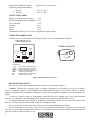
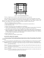
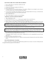
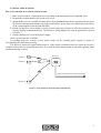
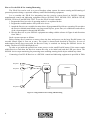
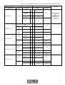
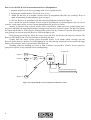
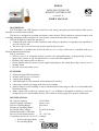
EFIR-K
ROLLING CODE UHF
REMOTE CONTROL SET
(version 2.2)
ISO 9001
USER’S MANUAL
DESCRIPTION
Efir-К Rolling Code UHF Remote Control Set is the strong encryption personal simplex radio system
intended to transmit control signals.
This device is designed as an alarm and remote control system. Efir-K enables to activate features such
as arming, disarming, utility and panic on your security system from the palm of your hand.
The Efir-К Remote Control Set consists of:
• 2-Button Keyfob, which is a RF transmitter with rolling (or dynamic, or hopping) code capability to
provide security, and
• Receiver, which is a wireless relay switch controlled by a Keyfob.
One transmitter is included into an Efir-K delivery set. A relay switch can be controlled with up to
fourteen additional transmitters.
Efir-К is useful to:
• Work as part of an integrated security systems (for arming/disarming, opening/closing of doors,
garage door openers or any movable barriers, or for notification appliances)
• Remote relay control of diverse devices
• Ensure human safety by means of panic signal transmitting to the Alarm Receiving Center in case of
intruder attack
• Provide a selected remote access
FEATURES:
•
•
Strong encrypted RF transmission
Remote control by up to 15 Keyfobs
•
•
•
•
Lost Keyfob disabling
LED indicating of relay actuation and learning mode entering
Choosing of suitable operating mode from four available
Built-in tamper switch enabling to detect unauthorized lid removing in order to avoid unauthorized
Keyfob operations
• Relay output with switch-over contacts (up to 3 A) enabling to manipulate remotely by such low
voltage devices as visual/audible alarms, video cameras, locks, garage door openers, and motors
SPECIFICATIONS
RF Carrier Frequency
433,92 MHz
Signal Encoding Technique
dynamic code
Receiver Working Range
up to 60 m
Number of Operating Modes
4
Keyfob RF Power Output
5,0 mW maximum
Maximum Number of Keyfobs
15
Receiver Power Requirements
10 ÷ 14,5 Vdc
Consuming Current (in case of 12 V voltage):
o for Non-Operating Relay 6 mA
o for Operating Relay
15 mA
1
Output NO/COM/NC Contacts
Operating Temperature Ranges:
o Keyfob
o Receiver
2А@120 Vac, 3A@24 Vdc
−10 C to +40 C
−30 C to +40 C
WHAT’S INCLUDED
Receiver (without power supply)
1 pcs
RF Keyfob with built-in accumulator 1 pcs
User’s Manual
1 pcs
Package
1 pcs
Screw
2 pcs
Dovel
2 pcs
Additional Keyfobs (up to 14) can be supplied in separate order.
OPERATING DIRECTIVES
The Receiver PC board layout and 2-Button Keyfob view are demonstrated in Figure 1.
Плата приемника
Receiver PCB
Радиобрелок
2-Button
Keyfob
Relay
LEARN
button
Large
Button1
кнопка
Receiver LED
Jumper J
Small
Button
кнопка
2
Tamper
switch
SC
12V+
1
2
Tamper
NO COM
3
1
4
2
NC
12V-
3
4
Light Indicator
индикатор
Terminals are:
−12 V
+12 V
Tamper
NO
COM
NC
SC
- Power supply negative pole input
- Power supply positive pole input
- Built-in tamper switch contacts
- Normally opened dry relay contact
- Common dry relay contact
- Normally closed dry relay contact
- reserved for use in future
Figure 1: Efir-K Remote Control Set
RECEIVER MOUNTING
Receiver overall and mounting dimensions in mm are represented in Figure 2.
Caution: The Receiver operating range is strongly dependent on its location, as well as on relative
receiver-transmitter position. Large building constructions and metal objects, power lines, vehicles as well as
humans can disturb RF propagation. Landscape details and surrounding vegetation can also attenuate the
signal.
In order to improve range of performance attach the Receiver upright away from strong thermal
sources, air conditioners, direct sunlight, places likely to cause water drops within the Receiver.
Technogenic/human factors should be minimized; particularly the RF sources other than signal from
Receiver. Avoid locations with constant strong electromagnetic fields.
Do not let the Receiver to touch metal objects or to be situated behind metal blinds.
Do not install the receiver close to concrete-steel constructions (less than 0,5 m apart). In case of fixing
to a concrete-steel wall use nonmetallic brackets or some other means so that there will be a distance between
a Receiver and a wall no less than 10 cm.
2
14
14
56
84
56
4 holes 3х8
84
Figure 2: Overall and Mounting Dimensions
The line of sight between a Receiver and a Keyfob should be free of obstacles.
Inspect the Receiver being placed at selected point detects the signals from all possible user locations.
In order to eliminate deadzones or to increase the operating range it can be possible to locate several
Receivers at various locations, the same Keyfobs being to be registered by each of them. In such a case
Receiver relay outputs can be connected either to the same or to diverse executive devices.
A Receiver mounting procedure is as follows.
1. Select the suitable location keeping in mind all recommendations mentioned above.
2. Take off the Receiver lid.
3. Firmly fix the Receiver base with supplied screws and dowels.
4. Wire the corresponding Receiver terminals to a power supply and an executive device in agreement
with required electrical scheme. Some typical application examples are specified below.
5. If necessary connect the Receiver tamper terminals to an available tamper alarm zone. The Receiver
tamper is brought into a scheme along with EOL resistor in series. The value of EOL resistor is
strongly dependent on specified connecting scheme and the equipment the tamper to be connected
to, so, this subject is beyond the scope of this manual.
6. Replace the Receiver lid.
7. Power up the Receiver and the executive device.
RECEIVER OPERATING MODES
A short pressing on the large Keyfob button activates the relay, while a short pressing on the small one
close the relay operation. The Keyfob light indicator lights up when a button is pressed (that is, the relay is
activated).
The relay can operate by four different ways (or modes) depending on the executive device required
behavior. The minimal relay actuating time shall not be less than 2 seconds irrespective of operating mode.
Mode #1: The relay is actuated by a large button pressing and remains on until the small Keyfob button
has not been pressed.
Mode #2: The relay is actuated by pressing on both large and small Keyfob buttons and remains on
until they have been released.
Mode #3: The relay is actuated by pressing on large Keyfob button and remains on until it has been
released.
Mode #4: The relay is actuated by a large button long pressing (more than 3 seconds) and remains on
until the small Keyfob button has not been pressed.
3
RECEIVER OPERATING MODE PROGRAMMING
1. Power off the Receiver and remove the Receiver lid.
2.
3.
4.
5.
Put on the jumper J.
Connect a 12 Vdc power supply to the Receiver.
Power on the Receiver.
Consider the Receiver periodically blinking. The number of flashes in sets (singly, by twos, in trees
or in fours) denotes the current operating mode number.
6. To increase the operating mode number press the large Keyfob button. Inversely, to decrement the
operating mode number press the small Keyfob button.
7. Power off the Receiver.
8. Take off the jumper J in order to save the changes.
ADDITIONAL KEYFOB PROGRAMMING
1. Take off the Receiver lid.
2. Connect the Receiver to a 12 ± 2 V direct power supply. Power on the Receiver.
3. Ensure there are no other operating RF transmitters closer than 50 meters.
4. Shortly (within no more than 2 seconds) press the LEARN button located on the Receiver PC board
to program a new Keyfob. The Receiver LED shall light up indicating programming mode initiating.
DCaution: Holding the LEARN button for more than 8 seconds will erase the Receiver memory so
that data about all Keyfobs programmed before will be lost.
5. Shortly press large or small Keyfob button and ensure the Receiver LED goes off. If the LED has no
gone off then the RF relationship between Receiver and Keyfob is not created.
DCaution: If the programming Keyfob button is not pressed within 30 second interval, having been
expired since Receiver programming mode initiating (pressing of the PC board LEARN button), the
programming mode will be prohibited. To resume the programming procedure return to the step 4.
6. In case of programming having been successful (the Receiver LED has gone off after pressing a
Keyfob button) press the Keyfob button once more.
7. To program another Keyfob (no more than 14 additional ones can be programmed) repeat the steps
from 4 to 6.
8. Bring the lid back onto the Receiver base.
9. Ensure all programmed Keyfobs are capable to operate properly having been located at the ordinary
places.
RECEIVER MEMORY CLEARING
Remove the Receiver lid and keep LEARN button pushed for more than 8 seconds. All Keyfobs data
having been already registered will be deleted.
4
TYPICAL APPLICATION
How to Use the Efir-K as a Panic Alarm System
1. Make your election of a required Receiver operating mode and program it as explained above.
2. Program the needful number of Keyfobs to be in use.
3. Attach the Receiver at a suitable location where all programmed Keyfobs are operating. Do not place
the Receiver behind metal blinds, near large metal objects, power lines, air conditioners and sources
of the electromagnetic, thermal and RF fields.
4. Include the Receiver into available security system connecting switch-over relay dry contacts to the
Security Station communication line. The Receiver wiring diagram for such an application is shown
in Figure 3.
5. Connect the Receiver to a usable power supply.
Such a system operates as follows.
As needing help any security system owner sends out an encoding panic signal by means of
corresponding Keyfob button pressing.
The Receiver detects the signal and decrypts it. If the signal is authentic Receiver opens the relay dry
contacts connected to the communication line. As a result Security Station alarm is activated signaling alarm
conditions having occurred.
Receiver
Keyfob 1
Keyfob 2
…………
Signal is transmitted to a Security Station
Keyfob 15
Figure 3: Using the Efir-K for Panic Signal Transmitting
5
How to Use the Efir-K for Arming/Disarming
The Efir-K Set can be used as a part of burglary alarm system for remote arming and disarming of
protected premises being co-operated with any control and indicating equipment.
Let us consider the Efir-K Set integrating into the security system based on BOLID Company
manufactured control and indicating equipment such as SIGNAL-VKA, SIGNAL-VK2, SIGNAL-VK-4P,
SIGNAL-VK4 iss.05 and SIGNAL-VK6. To use the Efir-K in such a manner:
1. Program the Receiver to be of operating mode #1 as explained before.
2. Program the needful number of Keyfobs to be in use.
3. Attach the Receiver at a suitable location where all programmed Keyfobs are operating. Do not place
the Receiver behind metal blinds, near large metal objects, power lines, air conditioners and sources
of the electromagnetic, thermal and RF fields.
4. Wire the Receiver to your SIGNAL equipment according with the scheme in Figure 4 and directions
from Table 1.
Such a system operates as follows.
Being coming out of premises an owner closes the door and presses on the large Keyfob button. An
encoded control signal is sent out at once. The signal is detected and decoded by Receiver. In case of
authorization having been successful, the Receiver relay is switched on forcing the SIGNAL device for
arming. The Receiver LED shall light by red.
In order to go inside the premises an owner presses on the small Keyfob button. If the owner stands
within Receiver reach then the Receiver returns the relay to its initial state and the LED goes down. The
SIGNAL device stops monitoring for protecting zones enabling entering inside object without any alarm.
Connecting of an Efir-K Receiver to a SIGNAL control and indicating equipment is specified in Table
1.
Receiver
Keyfob 1
SIGNAL
Keyfob 2
…………
Keyfob 15
12 VDC OUT
to NC
to COM
Figure 4: Using the Efir-K for Arming and Disarming
6
Burglary
Zone
Table 1: Connecting Efir-K Receiver to a SIGNAL Control and Indicating Equipment
Control and Indicating Equipment
Terminal
Model Name
Contact
Block
SIGNAL-VKA
SIGNAL-VK2
Efir-K Receiver
Terminal
Contact
Block
+12V
8
2
СОМ (common)
armed/
disarmed
11
3
NС (closed)
0V
7
4
-12V
+12V
8
2
+12V
Solder to the contacts 1 and 2 of
S3 switch
1
NO (opened)
ХТ2
ХТ2
ХТ2
-12V
12
2
СОМ (common)
ХТ2.3
+12V
11
2
+12V
ХТ1
ХТ2
-12V
12
4
-12V
ХТ2
Armed/
disarmed
11
2
СОМ (common)
Armed/
disarmed
12
3
NС (closed)
+12V
11
2
+12V
XT1
-12V
12
4
-12V
ХТ2
Crypto Device
-
1
NO (opened)
SIGNAL-VK-4P
ARMED/DISARMED
button
of SIGNAL-VKA
has to be set to
ARMED position,
that is
has to be pushed
ХТ1
ХТ2.3
ХТ3
Remarks
ХТ2
ХТ2
ХТ5
SIGNAL-VK4 iss. 05
ХТ2
ХТ21
SIGNAL-VK6
ХТ10
ХТ2
Crypto Device
-
2
СОМ (common)
+12V
9
2
+12V
XT1
-12V
10
4
-12V
ХТ2
Armed/
disarmed
1
3
NС (closed)
Armed/
disarmed
2
2
СОМ (common)
+12V
1
2
+12V
ХТ1
-12V
2
4
-12V
ХТ2
ХТ2
7
How to Use the Efir-K for Electromechanical Device Manipulation
1. Program the Receiver to be of operating mode #3 as explained before.
2. Program the needful number of Keyfobs to be in use.
3. Attach the Receiver at a suitable location where all programmed Keyfobs are operating. Keep in
mind all mounting recommendations given on page 3.
4. Wire the Receiver in accordance with the connecting diagram presented in Figure 5.
Let’s consider the specific example of such a system operating for an electromagnetic lock. In case of
sound or visual alarm, motor or video camera manipulations the process is similar.
Initially an entrance door is closed, and the lock is switched on. When an owner is about going away,
he presses and holds the large Keyfob button sending out an encrypted executive signal. The Receiver detects
the signal and decodes it. If the signal is authorized the switch-over dry contacts are opened following by the
lock opening. In such a process the Receiver LED shall light by red.
After having gone from the object the owner closes the door and releases the large Key button. The
Receiver LED shall go out. The lock switches on blocking the door.
Coming back the owner repeats actions described before. If he stands within coverage area the
Receiver opens the door, the Receiver LED lighting by red. After having entered the owner releases the large
button, after which the lock is closed and the LED goes out.
Dwelling within the building an owner in such a manner can provide a selective access control or
garage door opener (or any movable barrier) manipulating.
12 Vdc UPS
Receiver
Keyfob 1
−
+
Keyfob 2
COM NC
…………
End switch
To the electromagnetic lock
Keyfob 15
Figure 5: Using the Efir-K for Low Voltage Device Remote Control
8
WARRANTY
Manufacturer warrants its Efir-K Remote Control Set to be in conformance with specification under
normal transportation, storage, mounting and maintenance. The Efir-K Set average operating life is at least
10 years.
Manufacturer warrants its product to be free from defects in materials and workmanship for 12 months
since putting the Efir-K into operation, but no more then 18 months since production under normal use and
service.
Sending off the Efir-K to the manufacturer for repairing accompany those with a damage certificate
describing the defect. Send your complaints to the manufacturer at the following address:
ZAO NVP BOLID
#4, Pionerskaya street, Korolyov, Moscow Region, Russia, 141070
Tel./fax +7 495 777-40-20, +7 495 516-93-72.
E-mail: [email protected], Web-site: http://www.bolid.ru.
9
ACCEPTANCE CERTIFICATE
Efir-K Rolling Code UHF Remote Control Set
Product Designation
Serial Number
Produced, tested by quality control department in compliance with state standards and specifications, packed
by NVP BOLID Company and qualified as deliverable.
Q.C.
STAMP
10
_____________________
Name
____________________________
Date