1
BARCO PROJECTION SYSTEMS REALITY 6400 R9001760 R9001769 OWNER'S MANUAL Date : 04122000 Rev. : 03 Art. No. : R5976069 Federal communication commission (FCC statement) This equipment has been tested and found to comply with the limits for a class B digital device, pursuant to Part 15 of the FCC Rules. These limits are designed to provide reasonable protection against harmful interference when the equipment is operated in a commercial environment. This equipment generates, uses, and can radiate radio frequency energy and, if not installed and used in accordance with the instruction manual, may cause harmful interference to radio communications. Operation of this equipment in a residential area is likely to cause harmful interference in which case the user will be required to correct the interference at his own expense. Instructions to the user : if this equipment does cause interference to radio or television reception, the user may try to correct the interference by one or more of the following measures : Re-orientation of the receiving antenna for the radio or television. Relocate the equipment with respect to the receiver. Plug the equipment into a different outlet so that the equipment and receiver are on different branch circuits. Fasten cables connectors to the equipment by mounting screws. Note : The use of shielded cables is required to comply within the limits of Part15 of FCC rules and EN55022. Due to constant research, the information in this manual is subject to change without notice. Produced by BARCO NV, January 2000. All rights reserved. Trademarks are the rights of their respective owners. BARCO n.v./Projection Systems Noordlaan 5 B-8520 Kuurne Belgium Tel : +32/56/368211 Fax : +32/56/351651 E-mail : [email protected] Visite Barco at the web : http://www.barco.com Printed in Belgium Table of Contents TABLE OF CONTENTS --------------------------------------------------- I-1 UNPACKING AND DIMENSIONS -------------------------------------- 1-1 Projector dimensions ------------------------------------------------- 1-1 Unpacking --------------------------------------------------------------- 1-1 Battery installation in the RCU. ------------------------------------ 1-2 INSTALLATION GUIDELINES ------------------------------------------ 2-1 Installation Guidelines ------------------------------------------------ 2-1 Environment ------------------------------------------------------------ 2-1 Environment condition check -------------------------------------- 2-1 What about ambient light ? ----------------------------------------- 2-1 Which screen type? --------------------------------------------------- 2-2 What image size? How big should the image be? ---------- 2-2 Where to install the projector? ------------------------------------- 2-2 How to install a projection lens? ---------------------------------- 2-3 LOCATION AND FUNCTIONS OF CONTROL --------------------- 3-1 Front Panel Terminology -------------------------------------------- 3-1 Source & Power Connections -------------------------------------- 3-1 Communication Connections -------------------------------------- 3-2 Control Panel Terminology ------------------------------------------ 3-2 a. Local keypad -------------------------------------------------------- 3-2 b. Remote control ----------------------------------------------------- 3-3 INSTALLATION SET UP ------------------------------------------------- 4-1 Configuration ----------------------------------------------------------- 4-1 CONNECTIONS ------------------------------------------------------------- 5-1 Power connection ----------------------------------------------------- 5-1 AC Power (mains) cord connection ------------------------------ 5-1 Fuses --------------------------------------------------------------------- 5-1 Switching on ------------------------------------------------------------ 5-1 Lamp Run Time -------------------------------------------------------- 5-2 Lamp Run Time Warning ------------------------------------------- 5-2 Switching to Stand-by. ----------------------------------------------- 5-2 Switching Off ----------------------------------------------------------- 5-2 Input Connections ----------------------------------------------------- 5-2 5-cable Input Slot (slot 1) ------------------------------------------- 5-3 Computer input/Monitor output ------------------------------------ 5-4 Video Input -------------------------------------------------------------- 5-4 S-Video Input ----------------------------------------------------------- 5-5 Serial Digital Input / Serial Digital Output ----------------------- 5-5 IEEE 1394 Input ------------------------------------------------------- 5-6 Communication Connections -------------------------------------- 5-6 RS232 in / RS232 out ------------------------------------------------ 5-6 Communication port for communication with peripherals -- 5-7 Audio Connections ---------------------------------------------------- 5-7 CONTROLLING ------------------------------------------------------------- 6-1 How to use the RCU? ------------------------------------------------ 6-1 Projector address ----------------------------------------------------- 6-2 Displaying a Projector Address. ----------------------------------- 6-2 How to Program an Address into the RCU? ------------------- 6-2 Picture controls with direct access. ------------------------------ 6-2 Sound controls with direct access. ------------------------------- 6-3 The Pause key. -------------------------------------------------------- 6-3 The Selection key ----------------------------------------------------- 6-3 START UP OF THE ADJUSTMENT MODE ------------------------- 7-1 Adjustment Mode ------------------------------------------------------ 7-1 Color Temperature ---------------------------------------------------- 9-7 Gamma ------------------------------------------------------------------ 9-7 Decoding EBU/IRE ---------------------------------------------------- 9-7 Dynamic Color Depth ------------------------------------------------- 9-8 Noise Reduction ------------------------------------------------------- 9-8 Input Balance ----------------------------------------------------------- 9-8 Audio Tuning ----------------------------------------------------------- 9-9 Volume, Balance, Bass and Treble ------------------------------ 9-9 Mute ----------------------------------------------------------------------- 9-9 Fade ---------------------------------------------------------------------- 9-9 Mode [stereo]/[mono] ---------------------------------------------- 9-10 Video - Audio lock --------------------------------------------------- 9-10 Geometry -------------------------------------------------------------- 9-10 Shift --------------------------------------------------------------------- 9-11 Size --------------------------------------------------------------------- 9-11 Side Keystone -------------------------------------------------------- 9-11 Blanking ---------------------------------------------------------------- 9-12 Aspect Ratio ---------------------------------------------------------- 9-13 Options ----------------------------------------------------------------- 9-13 INSTALLATION MODE ------------------------------------------------- 10-1 Starting up the Installation Mode -------------------------------- 10-1 Input Slots ------------------------------------------------------------- 10-1 800 Peripherals ------------------------------------------------------ 10-2 Configuration --------------------------------------------------------- 10-2 OSD color (On-Screen Display) --------------------------------- 10-2 Internal Patterns ----------------------------------------------------- 10-3 No Signal -------------------------------------------------------------- 10-3 Lens Adjustments --------------------------------------------------- 10-3 Zoom/Focus/Shift --------------------------------------------------- 10-4 SERVICE MODE ---------------------------------------------------------- 11-1 Starting up the Service Mode ------------------------------------ 11-1 Identification ---------------------------------------------------------- 11-2 Change Password -------------------------------------------------- 11-3 How to enable or disable the password function ? --------- 11-3 How to change the password ? --------------------------------- 11-3 Change Language -------------------------------------------------- 11-3 Change Projector Address ---------------------------------------- 11-3 Change Baudrate PC ----------------------------------------------- 11-4 Reset Lamp Runtime ----------------------------------------------- 11-4 Lamp Run Time History ------------------------------------------- 11-4 Lamp Dimming ------------------------------------------------------- 11-4 Common Address --------------------------------------------------- 11-4 BARCO logo ---------------------------------------------------------- 11-4 Panel Adjustments -------------------------------------------------- 11-5 Uniformity -------------------------------------------------------------- 11-6 Preset Input Balance ----------------------------------------------- 11-6 I2C diagnosis. -------------------------------------------------------- 11-6 APPENDIX A : STANDARD SOURCE SET UP FILES ---------- A-1 APPENDIX B : LENSES ------------------------------------------------- B-2 Lens Cleaning Procedure ------------------------------------------ B-1 Lenses ------------------------------------------------------------------ B-2 APPENDIX C : SOURCE NUMBERS 81 - 86 AND 91 - 96 ----- C-1 Projector without any 800 peripheral connected. ------------ C-1 Projector with a 800 peripheral connected. ------------------- C-1 AUTO IMAGE ADJUSTMENT ------------------------------------------- 8-1 RANDOM ACCESS ADJUSTMENT MODE ------------------------- 9-1 Starting up the Random Access Adjustment Mode ---------- 9-1 File Service ------------------------------------------------------------- 9-2 Load File ----------------------------------------------------------------- 9-2 Edit File ------------------------------------------------------------------ 9-3 Rename ------------------------------------------------------------------ 9-5 Copy ---------------------------------------------------------------------- 9-5 Delete --------------------------------------------------------------------- 9-5 File Options ------------------------------------------------------------- 9-6 Picture Tuning ---------------------------------------------------------- 9-6 CTI ON/OFF ------------------------------------------------------------ 9-6 i-1 5976069 BARCOREALITY 6400 04122000 Unpacking and Dimensions 1 UNPACKING AND DIMENSIONS Unpacking To open the banding, pull on the clip as shown in the first drawing. Pull To open Take the projector out of its shipping carton and place it on a table. Save the original shipping carton and packing material, they will be necessary if you ever have to ship your projector. For maximum protection, repack your projector as it was originally packed at the factory. Contents of the complete unit (box) : 1 2 3 4 5 37 9 - 1 BARCOREALITY 6400 or 6400DLC (weight ± 17 kg or ± 37.4 lbs) - 1 remote control unit RCU + 2 batteries. - 1 power cable with outlet plug type CEE7 or ANSI 73.11 . - 1 owners manual - 1 safety manual Projector dimensions (units : mm) 25.4 mm = 1" 371.2 202.4 53.5 82.7 211.4 169.5 139.6 53.5 29.6 187.2 14 380.6 6 152.6 152.6 368.7 184.4 526.8 107.5 245.1 97.6 max 24 148.9 min 12 43 60 42 124.1 124.4 147.8 217.2 120.2 46 5976069 BARCOREALITY 6400 14032000 1-1 Unpacking and Dimensions Battery installation in the RCU. Two batteries are packed together with the RCU. Before using your RCU, install first these batteries. 1 2 3 4 Remove the battery cover on the backside by pushing the handle a little towards the bottom of the RCU. Lift up the top side of the cover at the same time. Insert the batteries as indicated in the RCU. Put the battery cover on its place. How to replace the batteries in the RCU ? To replace the batteries : 1 2 3 4 5 6 7 Remove the battery cover on the backside by pushing the handle a little towards the bottom of the RCU. Lift up the top side of the cover at the same time. Push on the + side of the battery towards the - side Lift up the battery at the same time. Repeat for the second battery. Insert the batteries as indicated in the RCU (battery type AA or LR6 or equivalent). Put the battery cover on its place. Note, only important if more than one projector is installed in the room : 1. the common address can be zero (0) or one (1). The standard RCU are setup for common address zero. To change the common address of the RCU, contact a BARCO service center. If it is necessary to program the projector address into the RCU, see chapter 'Controlling'. 2. projector address has to be reprogrammed everytime the battery is changed, the RCU will always switch to the default address. 1-2 5976069 BARCOREALITY 6400 14032000 Installation Guidelines 2 INSTALLATION GUIDELINES Installation Guidelines Careful consideration of things such as image size, ambient light level, projector placement and type of screen to use are critical to the optimum use of the projection system. Max. ambient temperature : 40 °C or 104 °F Min. ambient temperature : 0 °C or 32 °F The projector will not operate if ambient air temperature falls outside this range (0°C- 40°C or 32°F-104°F). * Environment Do not install the projection system in a site near heat sources such as radiators or air ducts, or in a place subject to direct sunlight, excessive dust or humidity. Be aware that room heat rises to the ceiling; check that temperature near the installation site is not excessive. * Environment condition check Warning: Harmful Environmental Contamination Precaution A projector must always be mounted in a manner which ensures the free flow of clean air into the projectors ventilation inlets. For installations in environments where the projector is subject to airborne contaminants such as that produced by smoke machines or similar (these deposit a thin layer of greasy residue upon the projectors internal optics and imaging electronic surfaces, degrading performance), then it is highly advisable and desirable to have this contamination removed prior to it reaching the projectors clean air supply. Devices or structures to extract or shield contaminated air well away from the projector are a prerequisite, if this is not a feasible solution then measures to relocate the projector to a clean air environment should be considered. Only ever use the manufactures recommended cleaning kit which has been specifically designed for cleaning optical parts, never use industrial strength cleaners on a projectors optics as these will degrade optical coatings and damage sensitive optoelectronic components. Failure to take suitable precautions to protect the projector from the effects of persistant and prolonged air contaminants will culminate in extensive and irreversible ingrained optical damage. At this stage cleaning of the internal optical units will be non-effective and impracticable. Damage of this nature is under no circumstances covered under the manufactures warranty and may deem the warranty null and void. In such a case the client shall be held solely responsible for all costs incurred during any repair. It is the clients responsibility to ensure at all times that the projector is protected from the harmful effects of hostile airborne particles in the environment of the projector. The manufacture reserves the right to refuse repair if a projector has been subject to wantful neglect, abandon or improper use. * What about ambient light ? The ambient light level of any room is made up of direct or indirect sunlight and the light fixtures in the room. The amount of ambient light will determine how bright the image will appear. So, avoid direct light on the screen. Windows that face the screen should be covered by opaque drapery while the set is being viewed. It is desirable to install the projection system in a room whose walls and floor are of non-reflecting material. The use of recessed ceiling lights and a method of dimming those lights to an acceptable level is also important. Too much ambient light will wash out of the projected image. This appears as less contrast between the darkest and lightest parts of the image. With bigger screens, the wash out becomes more important. As a general rule, darken the room to the point where there is just sufficient light to read or write comfortably. Spot lighting is desirable for illuminating small areas so that interference with the screen is minimal. 5976069 BARCOREALITY 6400 04122000 2-1 Installation Guidelines * Which screen type? There are two major categories of screens used for projection equipment. Those used for front projected images and those for rear projection applications. Screens are rated by how much light they reflect (or transmit in the case of rear projection systems) given a determined amount of light projected toward them. The GAIN of a screen is the term used. Front and rear screens are both rated in terms of gain. The gain of screens range from a white matte screen with a gain of 1 (x1) to a brushed aluminized screen with a gain of 10 (x10) or more. The choice between higher and lower gain screens is largely a matter of personal preference and another consideration called the Viewing angle. In considering the type of screen to choose, determine where the viewers will be located and go for the highest gain screen possible. A high gain screen will provide a brighter picture but reduce the viewing angle. Screen width For more information about screens, contact your local screen supplier. * What image size? How big should the image be? The projector is designed for projecting an image size (video) from 1.00m (3.3ft) to 6.00m (19.7ft) with a aspect ratio of 5 to 4. * Where to install the projector? Inputs and computer video format input compatibility : Only when the lens shift is in it's nominal position. Some examples : Definitions of the Abbreviation on drawings CD = Total distance between projector and ceiling or projector and floor. VIDEO and S-VIDEO COMPONENT VIDEO RGB ANALOG with STANDARD SYNC (SYNC ON GREEN or SEPARATE SYNC) RGB ANALOG with TRI-LEVEL SYNC (SYNC ON GREEN or SEPARATE SYNC) VGA : 640 x 480 pixels MAC : 640 x 480 pixels Super VGA : 800 x 600 pixels XGA : 1024 x 768 pixels S-XGA : 1280 x 1024 pixels sources up to 1600 x 1280 pixels Sources with pixel clock < 200 MHz SW = Screen width. Lens type selection. SH = Screen height (image height). a) Determine the required screen width. PD = Projector Distance, distance between screen and projector. b) Determine the approximate position of the projector in the projection room with regard to the screen and measure the projector-screen distance (PD). B = Distance between ceiling and top of the screen or between floor and bottom of the screen. A = Correction value, distance between bottom side of projector (without feet) and middle of the lens. Value to be subtracted from B to obtain the correct installation position. (A value is a constant value for all screen widths and type of lenses, A = 124.1 mm or 4.89 inch) c) Use the lens formulas in appendix B to find the best corresponding PD with regard to the measured projector-screen distance for the required screen width. The desired lens is determined (the order number is given in the tabel in the same appendix B). Start the installation procedure for the projector as described in the manual. 2-2 5976069 BARCOREALITY 6400 04122000 Installation Guidelines OFF-Axis installation ON-Axis installation CD = B - A Projector SIDE VIEW SH SIDE VIEW CD = B - A Screen Projector SH Screen Optical axis projection lens A’ PD Optical axis projection lens A PD B B CD CD Floor Floor SW SW Screen Screen TOP VIEW TOP VIEW SW SW SH SH Floor BACK VIEW Floor BACK VIEW * How to install a projection lens? The projector is supplied without any lens. The following lenses are available, or will become available (contact a Barco service center) as an option : QFD(1.27:1) R9840400 QFD(2.5:1) R9840290 QFD(1.4-2.1:1) R9840380 QFD(2.1-3.0:1) R9840390 QGD(3.5-4.5:1) R9840060 QFD(4.5-6.0:1) R9840100 QFD(7:1) R9840410 5976069 BARCOREALITY 6400 04122000 2-3 Installation Guidelines How to install the lens? 1. 2. 3. 4. 5. 6. 7. Take the lens out of its packing material. Open the lens cover of the projector by pivoting it up and take it off. Open both lens locks (B) by pulling them backwards. Unlock first by pulling clip (A) forwards. Put the lens on the lens holder. Fix the lens by closing both locks (B) until they are secured. Plug the wires of motor unit into the connector (C). Re-install the lens cover. Image 1 image 1 image 2 image 3 image 3 Image 2 Image 3 Image 4 2-4 5976069 BARCOREALITY 6400 04122000 Location and Functions of Control 3 LOCATION AND FUNCTIONS OF CONTROL Front Panel Terminology The front panel terminology can be divided into 'Source & power connections' and 'Communication connections'. Source & Power Connections 1 2 3 4 5 6 RC 3 VID EO R G S-V IDE O B 4 SDI H /C 7 SDO V 1 5 IEE E 1394 C OM PU T ER 8 6 T RIG 2 M ON ITO R M OU SE 9 R S232 IN A UD IO IN R S232 O UT A A UD IO IN B C OM M. PO R T AUDIO IN C 10 AUDIO OUT 11 1 Video input: 1cinch or 1 BNC connector, no loop through. 2 Power switch : 3 Power input : autoranging from 90 to 240 Vac. 4 S-Video 5 SDI and SDO : serial digital input and loop trough output. 2 x BNC terminals. 6 IEEE 1394 : not yet implemented. 7 5-cable input : can be software switched between Video, S-Video, RGB analog or Component Video. 8 Computer input 9 Monitor output : the monitor of your computer can be connected to this output if your computer is connected to the computer input. 10 Audio inputs : 3 audio inputs. Each audio input can be associated with arbitrary input. 11 Audio output '1' = on, '0' = off 5976069 BARCOREALITY 6400 21082000 3-1 Location and Functions of Control Communication Connections 1 2 3 4 5 6 8 9 10 7 RC 3 VIDE O R G S-VIDE O B 4 S DI H /C SDO V 1 5 IEEE 139 4 COMPU TER 6 TRIG 2 MONITOR MOUSE R S2 32 IN A UD IO IN RS2 32 O UT A AUDIO IN B C OMM. PO RT AUD IO IN C A UDIO OUT 1 TRIG : output voltage of 5 V when projector is on. 2 MOUSE : mouse output to be connect to the mouse input of a computer. The computer can now be controlled via the Executive Remote Control Unit. 3 RS232 IN : to allow communication with external computer, e.g. IBM PC or compatible, Macintosh ... 4 RS232 OUT : used to connect to next projector, RS232IN plug (communication link for PC or MAC to the next projector). 5 Communication port : allows communication with the 800 peripherals. 6 IR-Acknowledged : IR signals are recognized. IR-Received : IR signals are received but not recognized by the projector. 7 Projector mode indication : indicates the status of the projector. Light off : power switch is not pressed. Red light : power switch is pressed, projector in stand by mode. Green light : projector in operational mode. 8 Diagnostics code : a) source number b) error code : a two digit error code is displayed when something goes wrong inside the projector. 9 Remote : remote input for wired remote control. 10 IR receiver : receiver for control signals transmitted from the RCU. Control Panel Terminology The projector can be controlled by the local keypad or by the remote control unit. a. Local keypad The local keypad is located on the backside of the projector. 3-2 5976069 BARCOREALITY 6400 21082000 Location and Functions of Control b. Remote control This remote control includes a battery powered infrared (IR) transmitter that allows the user to control the projector remotely. This remote control is used for source selection, control, adaptation and set up. It includes automatic storing of : - picture controls (Brightness, Sharpness...) - settings Remote Control (RCU) Other functions of the remote control are : - switching between standby and operational mode. - switching to "pause" (blanked picture, full power for immediate restarting) - direct access to all connected sources. 18 1 2 F3 F2 F4 F5 F1 ADJ EXIT 3 16 4 15 14 ENTER 6 9 0 7 8 EXIT STANDBY 5 6 6 TEXT 3 4 SHARPN TINT BRIGHTN 1 2 PHASE COLOR CONTRAST TEXT 9 0 SHARPN 9 7 8 TINT 15 5 6 COLOR 5 3 4 BRIGHTN 14 1 2 CONTR 17 ENTER 5 PAUSE 7 8 16 17 PHASE 13 12 11 PAUSE 11 10 12 Local keypad TREBLE BALANCE BASS VOL 9 Terminology 1 Function keys : user programmable keys with functions for direct access. 2 ADJ. : to escape the adjustment mode. 3 Address key (recessed key), to enter the address of the projector (between 0 and 9). Press the recessed address key with a pencil, followed by pressing one digit button between 0 and 9. 4 Selection key : to direct access the zoom/focus/shift functions. 5 PAUSE : to stop projection for a short time, press 'PAUSE'. The image disappears but full power is retained for immediate restarting. 6 STBY : stand-by button, to start projector when the power switch is switched on and to switch off the projector without switching off the power switch. Attention : Switching to Stand-by. When the projector is running and you want to go to stand-by, press the stand-by key for 2 seconds until the message 'Saving data, please wait' is displayed. Do not press any longer on the stand-by key otherwise the projector will restart. 7 Mute : to interrupt the sound reproduction. 8 ? : Auto image, to center the image on the active LCD surface. 9 Digit buttons : direct input selection. 10 Audio controls : use these buttons to obtain the desired sound level (see also 'Controlling'). 11 Picture controls : use these buttons to obtain the desired picture analog level (see also 'Controlling'). 12 PHASE : used to remove the instability of the image. 5976069 BARCOREALITY 6400 21082000 3-3 Location and Functions of Control 13 FREEZ : press to freeze the projected image. 14 TEXT : when adjusting one of the image, e.g. controls during a meeting, the displayed bar scale can be removed by pressing 'TEXT' key first. To re-display the bar scale on the screen, press 'TEXT' key again. 15 ENTER : to start up the adjustment mode or to confirm an adjustment or selection in the adjustment mode. 16 Cursor Keys (on RCU) or '+' and '-' keys (cursor keys) on the local keypad : to make menu selections when in the adjustment mode or to zoom/focus when the direct access is active. Comparision between the cursor keys and the use of the '+' and '-' keys on the local keypad : RCU = local keypad cursor key up = '+' key up cursor key down = '-' key down cursor key right = '+' key right cursor key left = '-' key left Use the '+' and '-' keys (cursor keys) : to increase or decrease the analog level of the image controls when they are first selected. 3-4 17 EXIT : to leave the adjustment mode or to scroll upwards when in the adjustment mode. 18 RC operating indication : lights up when a button on the remote control is pressed. (This is a visual indicator to check the operation of the remote control) 5976069 BARCOREALITY 6400 21082000 Installation Set Up 4 INSTALLATION SET UP Configuration The projector can be installed to project images in four different configurations : front/table, front/ceiling, rear/table and rear/ceiling. Rear/Ceiling Front/Ceiling Rear/Table Front/Table Changing the configuration : To change the configuration of the projector, proceed as follow : 1 2 3 4 5 6 7 Press ENTER to start up the adjustment mode. Press the cursor key é or ê to select 'Installation'. Press ENTER to display the Installation menu. Press the cursor key é or ê to select 'Configuration'. Press ENTER to display the Configuration menu. The actual installed configuration will be highlighted. Press the cursor key é or ê to select the corresponding configuration. Press Adjust to leave the adjustment mode. ADJUSTMENT MODE Select a path from below : RANDOM ACCESS INSTALLATION SERVICE Source 01 Select with or then <ENTER> <EXIT> to return. INSTALLATION INPUT SLOTS 800 PERIPHERAL CONFIGURATION OSD COLOR INTERNAL PATTERNS NO SIGNAL LENS Select with or then <ENTER> <EXIT> to return. CONFIGURATION FRONT/TABLE FRONT/CEILING REAR/TABLE REAR/CEILING Select with or then <ENTER> <EXIT> to return. 5976069 BARCOREALITY 6400 21082000 4-1 Connections 5 CONNECTIONS Power connection AC Power (mains) cord connection Use the supplied power cord to connect your projector to the wall outlet. Plug the female power connector into the male connector at the front of the projector. The power input is auto-ranging from 90 to 240 VAC. RC 3 V ID EO G R S -V IDE O B 4 H/C S DI S DO 1 V 5 I EEE 1394 C OMPUTER 6 TRIG 2 MO NITO R 3 VIDEO RS2 32 IN M OUSE S-VIDEO AUDIO I N 4 RS23 2 O UT A AUDIO I N C OMM. PO RT B C A UD IO IN A UDIO IN 100-240 V 6-2.5 A 50-60 Hz SDI Fuses Warning For continued protection against fire hazard : - refer replacement to qualified service personnel - ask to replace with the same type of fuse. Fuse type : T10 AH/250V Switching on Use the power switch to switch on. F3 F2 Stand-by key When '0' is visible, the projector is switched off. When '1' is visible, the projector is switched on. When switching on with the power switch, the projector starts in the stand by mode. The projector mode indication lamp is red. To start image projection : a. press the 'Stand by' button once on the local keypad or on the remote control. The projector mode indication lamp will be green. b. press a digit button to select an input source. The projector mode indication lamp will be green. F4 F1 F5 ADJ EXIT ENTER 9 0 PAUSE EXIT STANDBY 7 8 5 6 TEXT 3 4 SHARPN 1 2 PHASE TEXT ENTER PHASE PAUSE 9 0 TINT BRIGHTN 7 8 TINT COLOR CONTRAST 5 6 COLOR 3 4 BRIGHTN 1 2 SHARPN CONTR TREBLE BALANCE BASS VOL Projector mode indication 5-1 5976069 BARCOREALITY 6400 14032000 Connections Lamp Run Time When the total run time of the lamp is X-30 hours or more, the following warning message will be displayed for 1 minute. This warning message will be repeated every 30 minutes. Press EXIT to remove the message before the minute is over. When the total run time of the lamp is 500 hours or more, the following warning message, with the exact run time is displayed on the screen. Lamp run time is X hours. Operating the lamp longer than X hours may damage the projector. Please replace the lamp. Remaining Lamp run time 20 h When OK (ENTER) is pressed to go on, the warning will be repeated every 30 min. The total lifetime of the lamp for a safe operation is X hours max. Do not use it longer. Always replace with a same type of lamp. Call a BARCO authorized service technician for lamp replacement. WARNING Lamp run time is X hours Operating the lamp longer than X hours may damage the projector. Please replace the lamp Lamp Run Time Warning Using a lamp for more than X hours is dangerous as the lamp could explode. <ENTER> to continue Switching to Stand-by. When the projector is running and you want to go to stand-by, press the stand-by key for 2 seconds until the message 'Saving data, please wait' is displayed. Do not press any longer on the standby key otherwise the projector will restart. Saving data, Please wait Switching Off To switch off: - First press STANDBY key for 2 seconds. When the message 'Saving data, please wait' is displayed, do not press any longer on the standby key otherwise the projector will restart. Let cool down the projector at least 10 min. - Switch off the projector with the power switch. Switching to Stand-by Warning When switching to standby, it is possible to restart within the first 5sec.. When not restarted within these first 5 sec., the projector waits for 1 min. to restart again. During this period the LED display will show a jumping square with a dash. After one minute, two dashes will be displayed and the projector can restart. Input Connections Input facilities : Video S-Video 5-cable input Computer Serial digital input IEEE 1394 (not yet active) Input Selection : This can be manually or automatically. When 'automatic' is selected in the Input slots menu, by starting up the projector, it searches for an input source by scanning the inputs one by one. If only one source is found, this source will be projected. If different sources are found, the priority is as follow : 1. Video 2. S-Video ADJUSTMENT MODE 3. 5 Cable input 4. Computer input Select a path from below : SDI input and IEEE input are never automatically selected. Note : When a RCVDS is connected to the projector, the 'Automatic' selection is disabled. Set up of the input selection : 1 2 3 4 5 6 7 8 Press ENTER to start up the adjustment mode. Press the cursor key é or ê to select 'Installation'. Press ENTER to display the Installation menu. Press the cursor key é or ê to select 'Input Slots'. Press ENTER to display the Input slots menu. Press the cursor key é or ê to select 'Input Slots'. Press ENTER to toggle between [Manual] or [Automatic]. Press EXIT several times to leave the adjustment mode. 5976069 BARCOREALITY 6400 14032000 RANDOM ACCESS INSTALLATION Select with or then <ENTER> <EXIT> to return. INSTALLATION INPUT SLOTS INPUT SLOTS Select with or thenSLOT <ENTER> SELECTOR [Automatic] <EXIT> to return. x 1. RGB [HS&VS] - 2. RGB [HS&VS] x 3. VIDEO - 4. S-VIDEO - 5. DIGITAL INPUT - 6. IEEE 1394 Select with or <ENTER> to toggle <EXIT> to return. 5-2 Connections Use of a RCVDS05 or VS05 : When using a RCVDS05, it is recommended to use a 5-cable output module in the RCVDS. The outputs of this module have to be connected to the 5 cable input (slot 1) of the projector. To switch the projector in the 5-cable mode see chapter 'Installation mode'. 5-cable Input Slot (slot 1) Slot 1 has 5 BNC input terminals. The following signals can be connected to these BNC connectors : Connector name R G B H V RGBHV R G B H V RGBS R G B S - RGsB R Gs B - - Composite Video - Video - - - Super Video - Y - - C Component Video - SS R-Y Y B-Y S - Component Video - SOY R-Y Ys B-Y - - Input signal 3 VIDEO R G 4 S-VIDEO B S DI H/C SDO V 1 5 IEE E 1394 C OM PUTER 6 TRIG 2 MONITOR M Slot 1 selection : Key in 1 on the RCU or the local keypad. Configuration of the 5-cable input : The configuration has to be done on the 'Input slot' menu. To change the signal format : 1 Press ADJUST or ENTER key to start up the Adjustment mode. Push the cursor key é or ê to select Installation Press ENTER. Press the cursor key é or ê to select 'Input Slots' Press ENTER. The internal system will scan the inputs and displays the result in the 'Input Slots' menu. Push the cursor key é or ê to select the first slot. Press ENTER key to toggle the input signal priority. 2 3 4 5 6 7 Possible indication : RGB [HS&VS] = RGB analog signals, separate sync is horizontal and vertical sync. RGB CS = RGB analog signals, separate sync is composite sync. RGB CV = RGB analog signals, separate sync is composite video or tri-level sync. RGB-SOG = RGB analog signals, sync on green is composite sync. COMPONENT VIDEO - CS = separate sync is composite sync. COMPONENT VIDEO = component video with composite sync on Y or composite tri-level sync on Y. VIDEO S-VIDEO ADJUSTMENT MODE Select a path from below : RANDOM ACCESS INSTALLATION SERVICE Select with or then <ENTER> <EXIT> to return. INSTALLATION INPUT SLOTS 800 PERIPHIRAL CONFIGURATION OSD COLOR INPUT SLOTS SLOT SELECTOR [Automatic] x x - 1. 2. 3. 4. 5. 6. RGB [HS&VS] RGB [HS&VS] VIDEO S-VIDEO DIGITAL INPUT IEEE 1394 Select with or <ENTER> to toggle <EXIT> to return. When using an RCVDS 05 with a 5 cable output module, connect these 5 cables to this 5-cable input slot (slot1) of the projector. All sources of the RCVDS can now be accepted by the projector. Audio connection : Connect the audio input to one of the 3 audio inputs. See 'audio configuration' in this chapter for more explanation. 5-3 5976069 BARCOREALITY 6400 14032000 Connections Computer input/Monitor output Connect the output of the graphical card of the computer to the Computer input of the projector (connection < 60 cm) or insert an interface between the output of the computer and the input of the projector. Connect the monitor of the computer to the monitor output of the projector. This monitor output is only available when the computer input is used as input. RC 3 VIDEO G R Pin configuration of the D15 connector : 9 1 RED 10 2 GREEN 11 3 BLUE 12 4 loop through to monitor 13 5 ground 14 6 ground 15 7 ground 8 ground S-V IDEO B 4 SDI 5 SDO H/C COM PUTER 1 V IEEE 1394 6 TRIG 2 M ONITO R M OUSE RS232 IN AUDIO IN COM M. PORT RS232 O UT A AUDIO IN B AUDIO IN C AUDIO IN loop through to monitor ground loop through to monitor loop through to monitor horizontal/composite sync vertical sync loop through to monitor Slot 2 selection : Key in 2 on the RCU or the local keypad. Video Input Input signal : Composite video signals from a VCR, OFF air signal decoder, etc... 1 x BNC or cinch 1.0Vpp ± 3 dB No loop through. Slot 3 Selection : Key in 3 on the RCU or the local keypad. RC 3 VID EO R G S-VIDEO B 4 SDI H/C SDO V 5 IEEE 1394 C OM PU TER 1 6 2 TRIG M ONITOR M OUSE RS232 IN AUDIO IN R S232 OUT A AUD IO IN B C OM M. PO R T AUD IO IN C AUD IO IN A, B or C or C o m p o site V id e o or T V tu n e r, e .g . M a rc o P o lo 5976069 BARCOREALITY 6400 14032000 VCR 5-4 Connections S-Video Input Input signal : Separate Y-luma/C-chroma signals for higher quality playback of Super VHS-signals. RC 3 VIDEO G R 4 S-VIDEO B SDI 5 SDO H/C 1 V IEEE 1394 6 T RIG 2 MONITO R COM PUTER M OUSE RS232 IN AUDIO IN COM M. PO RT RS232 O UT A B AUDIO IN AUDIO IN C AUDIO IN A, B or C Lum a/Chroma VCR S-VHS Pin configuration mini DIN plug : 1 2 3 4 ground luminance ground chrominance luminance 1.0Vpp ± 3 dB chrominance 282 mVpp ± 3 dB Slot 4 Selection : Key in 4 on the RCU or the local keypad. Serial Digital Input / Serial Digital Output Standard for the BarcoReality 6400DLC. Optional for the BarcoReality 6400. Full compatibility with digital Betacam, or digital video sources. This avoids the need for analog processing anywhere in the video production chain and guarantees the ultimate image quality. An active loop through of the SDI input signal is provided for monitoring or for double or triple stacking applications. RC 3 V IDEO R G S-VIDEO B 4 H/C SDI SDO V 1 5 IEEE 139 4 COM PUTER 6 TRIG 2 M ONITOR M OUSE RS23 2 IN A UDIO IN RS232 OUT A AUDIO IN B COM M. PORT AUDIO IN C A UDIO IN D ig ita l V id e o D IG IT A L V ID E O S O U R C E 5-5 5976069 BARCOREALITY 6400 14032000 Connections connections : 1 x BNC input and 1 x BNC output. The input is always 75 Ω terminated. The output impedance of the SDO is 75 Ω. Slot 5 Selection : Key in 5 on the RCU or the local keypad. Note : When a RCVDS05 is connected to the projector, the SDI input is available by keying in 85 on the RCU. IEEE 1394 Input Input not yet implemented. Communication Connections The following communication connections are available : RS232 in / RS232 out. Comm port for communication with peripheral (switchable between PPM and RC5) RC for remote cable connection with the RCU. MOUSE to control a PC with the projector remote control. TRIG : output voltage to control another device. RS232 in / RS232 out To connect a Computer, e.g. IBM PC (or compatible), Apple Macintosh to the RS 232 input of the projector to allow communicate between the computer and the projector. RC 3 VIDEO R G S-VIDEO B 4 SDI H/C SDO V 1 5 IEEE 1394 C OM PUTER 6 TRIG 2 MON ITO R MOU SE R S232 IN AUD IO IN RS232 OUT A AUDIO IN B C OMM. POR T AUD IO IN C AUD IO IN RS232 connection Applications : a) remote control : - easy adjustment of projector via IBM PC (or compatible) or MAC connection. - allow storage of multiple projector configurations and set ups. - wide range of control possibilities. - address range from 0 to 255. b) data communications : - sending data to the projector or copying the data from the projector to a hard memory device (hard disc, floppy, etc.). Set up of the Baud Rate for Communication with a Computer : See 'Change Baudrate PC' in chapter 'Service mode'. 5976069 BARCOREALITY 6400 14032000 5-6 Connections Communication port for communication with peripherals This port can be configured to accept PPM or RC5 coded signals. To change the port configuration see 800 Peripherals in Chapter Installation. Connecting a RCVDS 05 to the projector. - Up to 20 inputs with the RCVDS 05 and 90 inputs when RCVDS's are linked via the expansion module. Serial communication with the projector. Remote control buttons on the RCVDS to control the projector (source selection and analog settings). The selected source number will be displayed on a 2 digit display and the selected input module will be indicated with a LED on the rear. For more information about the use of the RCVDS 05, consult the owner's manual of the RCVDS05, order number : R5975765. Connecting a VS05 to the projector The VS05 can switch up to 5 Composite Video sources, 3 Super Video sources and 1 RGB analog or component video source to the projector. In addition, the audio signal proper to the source, can be switched to an audio amplifier or the audio input of the projector. Order number : R9827890 For more information about the use of the VS05, consult the VS05 owner's manual, order number : R5975245. TRIG Output 5 V output voltage to trigger an external device (max. 10mA). This voltage is available when the projector is on. MOUSE Mouse function is only available with the Executive Remote Control (Order number : R9829960). The computer can then be controlled via the projector. To activate this mouse function, handle as follow : 1 Start up your computer with the computer mouse plugged in. The mouse driver should be loaded. 2 Unplug the computer mouse without switching off the computer. 3 Plug the delivered cable between the mouse input of the computer and the mouse output of the projector. 4 Computer can now be controlled with the executive remote control. For more information about the mouse buttons or functions, consult the owner's manual of the Executive Remote Control. Warning : before swithing off, disconnect first the mouse cable. Mouse functions : Left click, right click or double click are the same as for a traditional mouse. For Click and drag : push for 2 seconds on the left (right) mouse button, the move the mouse arrow with the mouse navigator and click again very short on the left (right) mouse button to interrupt the drag function. Audio Connections Three audio inputs and one audio output are available. Each audio input can be associated with an input source using the control software of the projector. e.g. source 1 can be locked with audio input B. Locking an audio input to a source input : 1 2 3 4 5 6 7 8 9 Press ENTER to start up the adjustment mode. Press the cursor key é or ê to select 'Random Access'. Press ENTER to display the Random Access menu. Press the cursor key é or ê to select 'Audio Tuning'. Press ENTER to display the Audio Tuning menu. Press the cursor key é or ê to select 'Video-Audio lock'. Press the cursor key ç or è to select the desired source input. Press ENTER to toggle between [A], [B] or [C]. Press several times EXIT or ADJUST to return to the operational mode. See also 'Video - Audio lock' in chapter 'Random Access Adjustment Mode'. 5-7 5976069 BARCOREALITY 6400 14032000 Controlling 6 CONTROLLING The projector can be controlled with a. The RCU b. The hardwired RCU (cable is not included) c. The local keypad. Ceiling Controlling the projector with the RCU and the hardwired RCU is equal. How to use the RCU? a) Point the front of the RCU to the reflective screen surface. Screen IR sensor RCU b) RCU used in a hardwired configuration. RC 3 V IDE O R 4 S -VIDE O G B SDI H /C 6 TRIG 2 MON ITO R COMPUTER 1 V I EE E 13 94 5 SDO MO USE RS23 2 IN AUDIO IN RS232 O UT A AUDIO IN B CO MM. PO RT C A UD IO IN AUDIO IN Plug one end of the remote cable in the connector on the bottom of the RCU and the second side in the connector in the front panel of the projector labelled 'RC'. c) Point the front of the RCU directly at one of the IR sensors of the projector. RC 3 VI DE O R G S - VIDE O B 4 H/ C SDI SDO V 1 5 IE EE 1 39 4 6 COM PUT E R 2 T RIG M ONI TOR MO US E RS 2 32 I N A UDIO I N RS 2 32 OU T A AUD IO IN B COM M. P O RT A UDIO I N C AUDI O IN 45° When using the wireless remote control, make sure you are within the effective operating distance (30m, 100ft in a straight line). The remote control unit will not function properly if strong light strikes the sensor window or if there are obstacles between the remote control unit and the projector IR sensor. 45° F3 F2 45° 45° F5 ADJ F3 F2 F4 F1 EX IT F5 ADJ E XIT ENTE R ENTE R P AUSE PAUSE TEX T TEXT PHASE P HAS E 5976069 BARCOREALITY 6400 14032000 F4 F1 SHARPN SHARPN 9 0 TINT 7 8 COLOR 5 6 COLOR 3 4 BRI GHTN 1 2 CONT R 9 0 7 8 5 6 3 4 BRIGHTN 1 2 CONTR TREBLE BALANCE BASS VO L T INT TREBL E BALANCE BAS S VOL 6-1 Controlling Projector address a. Software set up of the projector address. See 'Change projector address' in chapter 'Service mode'. b. How to control the projector or projectors. The projector's address may be set to any value between 0 and 255. When the address is set, the projector can be controlled now : - RCU for addresses between 0 and 9. - computer, e.g. IBM PC (or compatible), Apple MAC, etc. for addresses between 0 and 255. Note : a projector will respond to a RCU set to the common address ('0' or '1') regardless of what address is set in the projector itself. c. Using the RCU. The RCU is default programmed with address 0 or 1, 'common address'. With that 'common address' programmed into the RCU, every projector, without exception will listen to the commands given by this RCU. If it is necessary to control a specific projector, than enter the projector address into the RCU (only when that address is between 0 and 9). The projector with the corresponding address will listen to that specific RCU. Common Address Every projector has a common address '0' or '1'. The choice between '0' and '1' can be selected in the Service mode. Displaying a Projector Address. Press the ADDRESS key (recessed key on the RCU) with a pencil. The projector's address will be displayed in a 'Text box'. This text box disappears after a few seconds. To continue using the RCU with that specific address, it is necessary to enter the same address with the digit buttons (address between 0 and 9) within 5 seconds after pushing the address key. For example : if the Address key displays projector address 003, then press "3" digit button on the RCU to set the RCU's address to match the projector's address. Do not press 003 digits. This will address the remote control to '0' and control all projectors in the room. If the address is not entered within 5 seconds, the RCU returns to its default address (zero address) and control all projectors in the room. PROJECTOR ADDRESS 001 How to Program an Address into the RCU? Press the ADDRESS key (recessed key on the RCU) with a pencil and enter the address with the digit buttons within 5 seconds after pushing the address key. That address can be any digit between 0 and 9. Picture controls with direct access. When an image control is pressed, a text box with a bar scale, icon and function name of the control, e.g. 'brightness...' appears on the screen (only if text is ON). See example screen. The length of the bar scale and the value of the numeric indication indicate the current memorized setting for this source. The bar scale changes as the control stick on the RCU is pressed or the + or - buttons on the local keypad. Brightness Control A correct 'brightness' setting is important for good image reproduction. Use the + button for a higher brightness. Use the - button for a lower brightness. BRIGHTNESS 0 127 Contrast Control A correct 'contrast' setting is important for good image reproduction. Adjust the contrast to the level you prefer, according to room lighting conditions. Use the + button for a higher contrast. Use the - button for lower contrast. Color Saturation Color saturation is only active for Video and S-Video. Adjust the color intensity of the picture. Use the + button for richer colors. Use the - button for lighter colors. 6-2 5976069 BARCOREALITY 6400 14032000 Controlling Tint Control Tint is only active for Video and S-Video when using the NTSC 4.43 or NTSC 3.58 system. Use the + button Use the - button. Sharpness Control. Use the + button for a sharper picture. Use the - button for a softer picture. Phase Control Use the control disc to adjust the phase. Freez key Press Freez to freeze the displayed image. Sound controls with direct access. When a sound control is pressed, a text box with a bar scale, icon and function name of the control, e.g. 'volume...' appears on the screen (only if text is ON). See example screen. The length of the bar scale indicates the current memorized setting for this source. The bar scale changes as the + or - buttons of the control are pressed. The picture controls can only be adjusted with the RCU. Volume Control Volume control adjusts the volume. Use the + button for a higher volume. Use the - button for a lower volume. Bass Control Bass control adjusts the bass level (low tones). Use the + button for more low tones. Use the - button for less low tones. Treble Control Treble control adjusts the treble level (high tones). Use the + button for more high tones. Use the - button for less hight tones. Balance Control Is only effective if a external amplifier with loudspeakers is connected to the audio output. The balance control adjust the sound level between the left and the right box. Use the + button for a higher sound level on the right box than on the left one. Use the - button for a higher sound level on the left box than on the right one. The Pause key. When the Pause key is pressed, the image projection is stopped, a blue screen will be displayed and the projector remains with full power for immediate restart. The sound is not interrupted. The display on front of the projector will show a "P". To restart the image : 1 2 3 press pause key, press exit key or select a source number. 5976069 BARCOREALITY 6400 14032000 6-3 Controlling The Selection key. When the Selection key is pressed, the zoom/focus/shift menu will be displayed inmediately. To focus or zoom the image : 1 2 Push the é or ê key to zoom and ç or è key to focus the image. When finished, press EXIT to return. To shift the image : 1 2 3 6-4 Press ENTER to switch to the shift menu Push the é or ê key to shift the image up or down and ç or è key to shift the image left or right. When finished, press EXIT to return Zoom/Focus Change with é,ê,ç,è <ENTER> to Shift <EXIT> to return 5976069 BARCOREALITY 6400 14032000 Start up of the Adjustment Mode 7 START UP OF THE ADJUSTMENT MODE Adjustment Mode All source parameters, picture and audio tuning, and geometry are made while in the 'Adjustment Mode'. Press the ADJUST or ENTER key to enter the 'Adjustment mode'. You are now in the 'Adjustment Mode'. 1 2 3 ADJUSTMENT MODE Select a path from below : AUTO IMAGE RANDOM ACCESS INSTALLATION SERVICE The cursor key (RCU) or '+ or '-' keys (local keypad) are used to make menu selections and also for adjustments. The ENTER and EXIT keys are used to move forward and backward through the menu structure. The ADJUST key can be used to terminate the adjustment mode while any path selection menu is displayed. Source 01 Select with or then <ENTER> <EXIT> to return. There are 4 possible paths to follow once in the Adjustment Mode. They are : Auto Image - Auto image will center the image on the LCD panel when a file is loaded. Installation - Installation should be selected if a new input module is installed or a new source is connected to an existing input module. Also when the projector is relocated in a new configuration. Random Access - Random Access should be selected to set up a new source. Service - Service should be selected if the user intends to change general settings such as password, language, address, etc.or some service actions as reset lamp run time, panel adjustments, etc. or get set-up information. Some items in the Adjustment mode are password protected. While selecting such an item, the projector asks to enter your password (Password protection is only available when the password strap on the controller module is ON, call an authorised service center to change the position of the password strap). Password : PASSWORD The password contains 4 digits. ENTER PASSWORD ---Use numeric keys Enter the digits with the numeric keys. Example : 2 3 1 9 <EXIT> to return The first digit position is highlighted. Enter with the numeric keys. The highlighted square jumps to the next position. Continue until all 4 digits are filled in. When your password is correct, you gain access to the selected item. When your password is wrong. The error message "Invalid password" is displayed on the screen. Press EXIT to continue and to return to the Service menu. Factory programmed password : 0000 Error Invalid password <EXIT> to return Once the password is correctly entered, all other password protected items are accessible without re-entering the password. When re-entering the Adjustment mode, it will be nessary to enter the password again when selecting a password protected item. Setting up your own password : See 'Changing password' in the Service mode. 5976069 BARCOREALITY 6400 14032000 7-1 Auto Image Adjust 8 AUTO IMAGE ADJUSTMENT Auto Image Adjustment Push the cursor key é or ê to highlight 'Auto Image' and press ENTER. With auto image, it is possible to switch the auto image function 'on' or 'off' and to adjust an existing image when the auto image function is off. ADJUSTMENT MODE Select a path from below : AUTO IMAGE RANDOM ACCESS INSTALLATION SERVICE Source 01 Select with or then <ENTER> <EXIT> to return. Adjust By selecting Adjust the image will be centered on the active area of the LCD surface. The centering will be done by adapting the values for 'pixel start', 'pixel end', 'line start' and 'line end'. To center the image : 1 Push the cursor key é or ê to highlight 'Adjust'. 2 Press ENTER to activate. The image will be centered on the LCD surface. This is the same function as the '?' key on the remote control when in operational mode. The menu is automatically exited. The adjustment values will be saved when switching to another source. ADJUSTMENT MODE Select a path from below : AUTO IMAGE RANDOM ACCESS INSTALLATION SERVICE Select with or then <ENTER> AUTO IMAGE <EXIT> to return. ADJUST ACTION : FULL AUTOMATIC Select with or then <ENTER> <EXIT> to return. Action The action function can be toggled between : - full automatic - on new file - manual [full automatic] : the best fitting file will be loaded automatically when a source is selected. At the same time the image will be automatically centered on the active surface of the LCD. The centering of the image will be disabled when : 1 The black edges of the image take more than 25% of the complete image. 2 The connected source is video, s-video, digital video or HDTV. 3 Custom file already exists. [on new file] : only on a new file, the image will be centered on the active surface of the LCD. [manual] : the auto image function is switched OFF, no centering, no file load. To setup the Action function : 1 Push the cursor key é or ê to highlight 'ACTION'. 2 Press ENTER to toggle between FULL AUTOMATIC, ON NEW FILE and MANUAL. The values of automatically adjusted sources will not be saved. 7-1 5976069 BARCOREALITY 6400 21082000 Random Access Adjustment Mode 9 RANDOM ACCESS ADJUSTMENT MODE Starting up the Random Access Adjustment Mode Push the cursor key é or ê to highlight 'Random Access' and then press ENTER. LOAD EDIT RENAME FILE SERVICE ADJUSTMENT MODE Select a path from below : AUTO IMAGE RANDOM ACCESS INSTALLATION SERVICE Source 01 Select with or then <ENTER> <EXIT> to return. COPY DELETE OPTIONS CTI COLOR TEMPERATURE RANDOM ACCESS ADJUSTMENT MODE GAMMA PICTURE TUNING DECODING DYNAMIC COLOR DEPTH NOISE REDUCTION INPUT BALANCE VOLUME BALANCE BASS TREBLE AUDIO TUNING MUTE FADE MODE STEREO/MONO VIDEO - AUDIO LOCK SHIFT SIZE SIDE KEYSTONE GEOMETRY BLANKING ASPECT RATIO OPTIONS 5976069 BARCOREALITY 6400 14032000 8-1 Random Access Adjustment Mode File Service Before using a new source, a correct file has to be installed. The projector's memory contains a list of files corresponding to the most used sources. When the new source corresponds with one of these files, the file can be loaded and saved for future use. When there is a little difference, the file can also be loaded and then edited until the source specs are reached. Note : file loading can be done automatically (see File Options, in this chapter). Files with a ~ in front of the file name are tempory files. These files will be deleted when switching to another source. File annotation : xxxxxxxx.xxx x xxxxXxxxxi i or blank : i = interlaced, blank = not interlaced xxxxXxxxx : active pixel rating x : source number xxx : file extension, first character is C (for custom made files) or S (for standard files). The second and third character is used for a following number (=file index) file index for custom files : 00 to 63. xxxxxxxx : base name, 8 characters. To enter the File Service, handle as follow : 1 2 Pushing the cursor key é or ê to highlight 'File Service'. Press ENTER to select. The File service menu will be displayed. Note : EXIT returns to the Path selection menu. ADJUST returns to operational mode. The following file manipulations are possible : - Load : installation of a file for a new source. - Edit : editing a loaded file to the source specs. - Rename : renaming a file. - Copy : copying a file to a new file. - Delete : deleting an existing file. - Options : way of sorting the files. RANDOM ACCESS ADJUSTMENT MODE FILE SERVICE PICTURE TUNING AUDIO TUNING GEOMETRY Select with or then <ENTER> FILE SERVICE <EXIT> to return. LOAD EDIT RENAME COPY DELETE OPTIONS Select with or then <ENTER> <EXIT> to return. Load File 1 2 Push the cursor key é or ê to highlight 'Load'. Press ENTER to select. The Load menu displays the corresponding files depending on the installed filter. This filter can be "Fit" or "All". To change the filter : 1 Push the cursor key è or ç highlight 'filter list'. 2 Press ENTER to toggle the annotation between brackets. "All" : all files that can be loaded will be displayed. "Fit" : only the best fitting files will be displayed (with a distinction of ± 2 lines and line duration distinction of ± 300 ns, if nothing is found within this small area, the projector continues searching until it finds something.) To load a file : 1 Push the cursor key é or ê to select the best fitting file. 2 Press ENTER to select. A confirm Load file menu will be displayed with the newly created file and the one on which the new file is based on. 3 Press ENTER to confirm the new creation or EXIT to return to the load file menu. Note: When scrolling through the files, the image will be adapted according to the settings of the selected file (on line adaptation). FILE SERVICE LOAD EDIT RENAME COPY LOAD FILE Select with or FILTER LIST [All] then <ENTER> Filename Src Resolution <EXIT> to return. ----------------------------------------------------Video525.s01 1 675x240i Video525.c01 1 675x240i Video525.c02 1 675x240i ----------------------------------------------------Active file : Video525.c50 Select with or , <ENTER> to accept <EXIT> to return. CONFIRM LOAD FILE Create file Video525.c02 based on file Video525.s01? <ENTER> to confirm <EXIT> to return If the displayed image is not correct after selecting the best fitting file, go to the Edit menu, select the active file and change the File settings. During a load file, the actual active file is displayed next to the indication 'Active file'. 8-2 5976069 BARCOREALITY 6400 14032000 Random Access Adjustment Mode Edit File The Edit file menu makes it possible to change the settings of the file according to the real settings of the connected source. Consult the source specification before entering the data. To start up the EDIT menu: 1 Push the cursor key é or ê to highlight 'Edit'. 2 Press ENTER to select. The Edit file adaptation menu will be displayed. 3 Select the file which must be edited (mostly the active file). 4 Press ENTER. The file name will be displayed in the upper right corner. The following items can be adjusted : Total quantity horizontal pixels Active quantity horizontal pixels Horizontal start in pixels Horizontal period in µs (is automatically adapted during the installation of a file with LOAD) Total vertical lines (is automatically adapted during the installation of a file with LOAD) Active vertical lines Vertical start in lines Interlaced : toggle on/off (is automatically set to its correct position during the installation of a file with LOAD) FILE SERVICE LOAD EDIT RENAME COPY EDIT FILE Select with or then <ENTER> Filename Src Resolution <EXIT> to return. ----------------------------------------------------Video525.s01 1 675x240i Video525.c01 1 675x240i Video525.c02 1 675x240i All settings can individually be changed. 1 Push the cursor key é or ê to select an item. The color of the selected item will change and follow one of the three methods to change the value. ----------------------------------------------------Active file : Video525.c50 Select with or , <ENTER> to accept <EXIT> to return. EDIT FILE HORIZONTAL TOTAL ACTIVE START PERIOD VERTICAL (FIELD) TOTAL ACTIVE START INTERLACED READ AMDS OPTIONS , , , xga.s30 1344 PIXELS 1024 PIXELS 296 PIXELS 20.678 µS 806 LINES 768 LINES 36 LINES [OFF] <ENTER>, <EXIT> a. method 1: 1 press ENTER to activate the digits 2 enter directly with the numeric keys on the RCU or local keypad the new value or b. method 2: 1 Press ENTER to activate the digits 2 Push the cursor key è or ç to select the changing digit. 3 Push the cursor key é or ê to scroll to desired digit. 4 When finished press ENTER to confirm. c. method 3 1 Counting up or down by pushing the cursor key è or ç . How to find the correct values for the displayed item? During the installation of a file with LOAD, the horizontal period, the total number of vertical lines and the interlaced mode are automatically measured and filled in in the menu table. These values will be available when starting up the EDIT procedure of an active file. (Caution : Do not adjust these settings on an active file, they are used to identify the input source file.) If the value for "Horizontal Total Pixels" is wrong, sampling mistakes (small vertical bars in the projected image) will be seen in the image. Select "Total" and adjust the pixel quantity. Adjust for zero bars (hint: if the number of bars increase, adjust in the other direction). The "Active Pixels" : determine the width of the window on the screen. This value is normally given in the source specifications. If not, adjust until full image is displayed (no missing pixels). "Horizontal Start" : number of pixels between the beginning of the input signal and the start of the video information in the signal. "Horizontal Period" : already filled in with the correct value when active file. (see caution above). The "Vertical Total Lines" are already filled when an active file is selected to be edited (see caution above). The "Active Lines" : number of horizontal lines determining the height of the projected image. This value is normally given in the specification of the source. If not, adjust until full image height is displayed (no missing lines) Vertical start : number of lines between the start of the input signal and start of the image on the screen. Interlaced [On] or [Off] : this selection is automatically filled when active file has to be edited. If the image is wrong due to mismeasurement, use the ENTER key to toggle between [On] and [Off]. (for interlaced images, 1 frame contains 2 fields). 5976069 BARCOREALITY 6400 14032000 8-3 Random Access Adjustment Mode Read AMDS AMDS = automatic mode detection & synchronisation During the installation of a file with LOAD, the system automatically measured the horizontal period, the total vertical lines and the interlaced mode. When selecting Read AMDS, the system remeasures the above indicated items. Options Source Number : The source number of a non-active source can be changed to any other source number. This makes it possible to create a file for future source numbers. EDIT FILE OPTIONS Source number 1 Clamp position [leading] Clamp delay 0 Clamp width 10 Field polarity [pos] Field select [both] Vertical refresh [sync] Vertical sync polarity [leading] Clamp Position : Clamping determines the black level of the signal. The clamp pulse can be related to the leading or the trailing edge of the sync pulse. Use the ENTER key to toggle between [leading] and [trailing]. Select with or <ENTER> to toggle or to change value <EXIT> to return Clamp Delay : The time between the leading edge of the clamp pulse and the locked edge of the sync pulse. Can be any value between 0 and 255. Change the value by pushing the cursor key è or ç. Field Select : Default [both] The field select is only used for interlaced images. One frame of an interlaced image contains two fields, an even and an odd field. The choice exists to project [both] fields on the screen or only the [even] or [odd] field. This can be useful for 3D projection. Use the ENTER key to toggle between [both], [even] and [odd]. trailing edge Field Polarity : The field polarity function is used for interlaced images. Both rasters of the image could be shifted in a wrong way (double lines are visible in the image). This can be corrected by forcing the field polarity to [neg] or [pos]. Use the ENTER key to toggle between [pos] and [neg]. xample for clamp position [trailing] leading edge Clamp Width : The width of the clamp pulse Can be any value between 0 and 255. Change the value by pushing the cursor key è or ç. Sync pulse Clamp pulse Clamp width Clamp delay Vertical Refresh [sync/async] : The way of updating the image information on the LCD panels. Not available for PAL-NTSC-SECAM sources. This option will be displayed in gray. * For sources with a vertical frequency up to 60 Hz : the vertical refresh rate is the same as the vertical frequency of the incoming source. This is a necessity to project moving images without 'motion artifacts'. For stationary images with a vertical frequency up to 60 Hz it is still possible to use asynchronous refresh. When loading Pal, Secam, NTSC-files the synchronous mode is default, for all other sources below 60 Hz asynchronous mode is default. * For sources with a vertical frequency higher that 60 Hz : the vertical refresh is different than the vertical frequency of the incoming source. Synchronous refresh cannot be used. Vertical Sync Polarity : [leading] or [trailing] The vertical refresh can be synchronised with the leading sync edge or trailing sync edge. Default on [leading]. Toggling to [trailing] is only necessary for special applications where the trailing edge of the sync signal has to be taken as a reference. Use the ENTER key to toggle between [leading] or [trailing] Press EXIT to leave the Edit File Option menu. A 'Confirm Edit File' menu will be displayed. Press ENTER to confirm and to save the new settings or EXIT to return without saving the new entered settings. CONFIRM EDIT FILE Save changes to file xga.c30? <ENTER> to confirm <EXIT> to return 8-4 5976069 BARCOREALITY 6400 14032000 Random Access Adjustment Mode Rename To change the name of a selected file: 1 Push the cursor key é or ê to highlight 'Rename'. 2 Press ENTER. The Rename selection menu will be displayed. 3 Push the cursor key é or ê to select a file name. 4 Press ENTER to select. FILE SERVICE LOAD EDIT RENAME COPY DELETE The Rename menu will be displayed with the selected file name already filled in, leave in the 'From file name :' area and in the 'To file name :' area. Select with or RENAME FILE then <ENTER> <EXIT> to return. Filename Src Resolution ----------------------------------------------------Video525.s01 1 675x240i Video525.c01 1 675x240i Video525.c02 1 675x240i ----------------------------------------------------Active file : Video525.c50 Select with or <ENTER> to accept <EXIT> to return. The first character is highlighted. 1 Push the cursor key ç or è to select the desired character. 2 Change that character by pushing the cursor key é or ê. Numeric characters can be entered directly with numeric keys on the RCU. 3 Press ENTER to confirm. The renamed file is entered in the list of files. 4 Press EXIT to return to the Rename menu selection. No changes are made. RENAME FILE Frome file name : Video525.s01 To file name : demo.c10 Select with or Reprogram with or or numeric keys <ENTER> to confirm <EXIT> to return Copy To copy a selected file into a new file : 1 Push the cursor key é or ê to highlight 'Copy'. 2 Press ENTER. The Copy selection menu will be displayed. 3 Push the cursor key é or ê to select a file name. 4 Press ENTER to select. The Copy menu will be displayed with the selected file name already filled in, in the 'From file name :' area and in the 'To file name :' area. The first character is highlighted. 1 Push the cursor key ç or è to select the desired character. 2 Change that character by pushing the cursor key é or ê. Numeric characters can be entered directly with numeric keys on the RCU. 3 Press ENTER to confirm. The renamed file is entered in the list of files. 4 Press EXIT to return to the Copy menu selection. No changes are made. FILE SERVICE LOAD EDIT RENAME COPY DELETE Select with or COPY FILE then <ENTER> <EXIT> to return. Filename Src Resolution ----------------------------------------------------Video525.s01 1 675x240i Video525.c01 1 675x240i Video525.c02 1 675x240i ----------------------------------------------------Active file : Video525.c50 Select with or <ENTER> to accept <EXIT> to return. COPY FILE Frome file name : xga_60.s03 To file name : xga_60.c14 Select with or Reprogram with or or numeric keys <ENTER> to confirm <EXIT> to return Delete To delete a selected file out of the list of files : 1 Push the cursor key é or ê to highlight 'Delete'. 2 Press ENTER. The delete selection menu will be displayed. 3 Push the cursor key é or ê to select a file name. 4 Press ENTER to select. If [All] is selected, your password has to be entered before all files will be deleted. FILE SERVICE LOAD EDIT RENAME COPY DELETE OPTIONS Select with or then <ENTER> <EXIT> to return. DELETE FILE Filename Src Resolution ----------------------------------------------------Video525.s01 1 675x240i Video525.c01 1 675x240i Video525.c02 1 675x240i ----------------------------------------------------Active file : Video525.c50 Select with or <ENTER> to accept <EXIT> to return. 5976069 BARCOREALITY 6400 14032000 8-5 Random Access Adjustment Mode A confirmation menu "Delete file 'file name'?" is displayed. When you want to delete the file, press ENTER. If you do not want to delete the file, press EXIT. Note : the active file cannot be deleted. CONFIRM DELETE FILE Delete file: Video525.c01? <ENTER> to confirm <EXIT> to return File Options 1 2 Push the cursor key é or ê to highlight 'File Options'. Press ENTER. The option selection menu will be displayed. File Sort Press ENTER to toggle between [name] and [index] [name] : The files in the file list will be sorted on the file name. [index] : The files in the file list will be sorted on the file extension. FILE SERVICE LOAD EDIT RENAME COPY DELETE OPTIONS Select with or then <ENTER> <EXIT> to return. FILE OPTIONS FILE SORT [NAME] Select with or then <ENTER> <EXIT> to return. Picture Tuning 1 2 Push the cursor key é or ê to highlight 'Picture Tuning'. Press ENTER to select. The Picture Tuning menu will be displayed. The next items are available : - CTI ON/OFF - color temperature - gamma - decoding EBU/IRE - dynamic color depth - noise reduction - input balance RANDOM ACCESS ADJUSTMENT MODE FILE SERVICE PICTURE TUNING AUDIO TUNNING PICTURE TUNING Select with or then <ENTER> CTI [ON] <EXIT> to return. COLOR TEMPERATURE GAMMA DECODING [EBU] DYNAMIC COLOR DEPTH NOISE REDUCTION INPUT BALANCE Select with or then <ENTER> <EXIT> to return. CTI ON/OFF CTI : Color Transient Improvement. To improve the transition from one color to another. 1 2 Push the cursor key é or ê to highlight 'CTI'. Press ENTER to toggle between ON and OFF. This function applies to PAL and NTSC video or S-video inputs only. 8-6 PICTURE TUNING CTI [ON] COLOR TEMPERATURE GAMMA DECODING [EBU] DYNAMIC COLOR DEPTH NOISE REDUCTION INPUT BALANCE Select with or then <ENTER> <EXIT> to return. 5976069 BARCOREALITY 6400 14032000 Random Access Adjustment Mode Color Temperature 1 2 Push the cursor key é or ê to highlight 'Color Temperature'. Press ENTER to select. The color temperature selection menu will be displayed. The next choices are possible : - Projector white Broadcast 3200 Film 5400 Video 6500 Computer 9300 Custom balance. K K K K PICTURE TUNING CTI [ON] COLOR TEMPARATURE GAMMA DECODING [EBU] DYNAMIC COLOR DEPTH COLOR TEMPERATURE PROJECTOR WHITE COMPUTER 9300K VIDEO 6500K FILM 5400K BROADCAST 3200K CUSTOM BALANCE Select with , then <ENTER> <EXIT> to return. Push the cursor key up or down to select a fixed color temperature or custom balance. Projector white will provide maximum projector light output. The calibrated 'Broadcast', 'Film', 'Video' and 'Computer' presets will provide optimum color tracking. Custom balance allows the user to set his own preferred color temperature. To adjust Custom Balance, handle as follow : 1 Push the cursor key é or ê to highlight 'Custom Balance'. 2 Press ENTER to select. 3 Push the cursor key é or ê to adjust red and push the cursor key ç or è to adjust blue (range 0 to 2.5) in comparison with the green color (value 1). GAIN RED 2.5 0 Gamma With the gamma correction adjustment, it is possible to accurately set the gamma of the projector image. To change the gamma value : 1 Push the cursor key é or ê to highlight 'Gamma'. 2 Press ENTER to select. 3 Change the gamma value by pushing the cursor key ç or è until the desired value is reached. 4 Press EXIT to return to the Picture Tuning menu. PICTURE TUNING CTI [ON] COLOR TEMPERATURE GAMMA DECODING [EBU] DYNAMIC COLOR DEPTH NOISE REDUCTION GAMMA = 2.2 3 Decoding EBU/IRE Only for NTSC signals. The possibility is offered to decode the NTSC video signals via the default American IRE standard or via the European EBU standard. Decoding a NTSC signal using the European EBU standard may result in a greenish tint. 1 2 3 Push the cursor key é or ê to highlight 'Decoding'. Press ENTER to toggle between EBU or IRE. Press EXIT to return. 5976069 BARCOREALITY 6400 14032000 PICTURE TUNING CTI [ON] COLOR TEMPERATURE GAMMA DECODING [EBU] DYNAMIC COLOR DEPTH NOISE REDUCTION INPUT BALANCE Select with or then <ENTER> <EXIT> to return. 8-7 Random Access Adjustment Mode Dynamic Color Depth PICTURE TUNING Increases color contrast for all video and data sources. To change the dynamic color depth value : 1 Push the cursor key é or ê to highlight 'Dynamic Color Depth'. 2 Press ENTER to select. 3 Change the value by pushing the cursor key ç or è until the desired color contrast is reached. Adjustment range : 0 ... 8 Default : 4 4 Press EXIT to return to the Picture Tuning menu. CTI [ON] COLOR TEMPERATURE GAMMA DECODING [EBU] DYNAMIC COLOR DEPTH NOISE REDUCTION INPUT BALANCE Select with or then <ENTER> <EXIT> to return. DYNAMIC COLOR DEPTH 4 8 0 Noise Reduction Reduces noise and pixel jitter in all video and data sources. To change the noise reduction value : 1 Push the cursor key é or ê to highlight 'Noise Reduction'. 2 Press ENTER to select. 3 Change the value by pushing the cursor key ç or è until the desired noise level is reached. Adjustment range : 0 ... 8 4 Press EXIT to return to the Picture Tuning menu. PICTURE TUNING CTI [ON] STILL VIDEO [ON] COLOR TEMPERATURE GAMMA DECODING [EBU] DYNAMIC COLOR DEPTH NOISE REDUCTION INPUT BALANCE Select with or then <ENTER> <EXIT> to return. NOISE REDUCTION 0 8 Input Balance Attention : Before starting the Input Balance function, generate a signal with dominant black and white areas. The default values are normally loaded when selecting a source. If the image is not as desired, adjust for this source as follow : Start with the Black Balance : 1 Push the cursor key é or ê to highlight 'Black Balance'. 2 Press ENTER to select. 3 Adjust the Brightness to a maximum value until there is just no green noise visible in the black areas. 4 Adjust with the cursor key é or ê or ç or è until there is no red or blue noise visible in the black areas. Continue with the White Balance : 1 Push the cursor key é or ê to highlight 'White Balance'. 2 Press ENTER to select. 3 Adjust the Contrast to a maximum value until the white areas are just white (without green noice) and return one step. 4 Adjust with the cursor key é or ê or ç or è until there is no red or blue noise visible in the white areas. 8-8 PICTURE TUNING CTI [ON] STILL VIDEO [ON] COLOR TEMPERATURE GAMMA DECODING [EBU] DYNAMIC COLOR DEPTH NOISE REDUCTION INPUT BALANCE Select with or then <ENTER> <EXIT> to return. INPUT BALANCE WHITE BALANCE BLACK BALANCE DEFAULT Select with or then <ENTER> <EXIT> to return. 5976069 BARCOREALITY 6400 14032000 Random Access Adjustment Mode Audio Tuning 1 2 Push the cursor key é or ê to highlight 'Audio Tuning'. Press ENTER to select. The Audio Tuning menu will be displayed. The following items are available : - Volume - Balance - Bass - Treble - Mute - Fade - Mode - Video - Audio lock RANDOM ACCESS ADJUSTMENT MODE FILE SERVICE PICTURE TUNING AUDIO TUNING GEOMETRY 1 [A] AUDIO TUNING VOLUME BALANCE BASS TREBLE MUTE [OFF] FADE MODE [STEREO] VIDEO - AUDIO LOCK 2 3 4 5 6 [C] [B] [A] [B] [A] Select with or then <ENTER> <EXIT> to return. Volume, Balance, Bass and Treble When a sound control is selected by highlighting the item with the cursor key, a text box with a bar scale, icon and function name of the control, e.g. 'Volume' appears on the screen (only when text is ON). The length of the bar scale indicates the current memory setting for this source. For more information about the sound controls, see 'Sound controls with direct access' in the Chapter 'Controlling'. Mute To stop the sound reproduction. 1 Push the cursor key é or ê to highlight 'Mute'. 2 Press ENTER to toggle between [on] or [off] 1 [A] AUDIO TUNING VOLUME BALANCE BASS TREBLE MUTE [OFF] FADE MODE [STEREO] VIDEO - AUDIO LOCK 2 3 4 5 6 [C] [B] [A] [B] [A] Select with or then <ENTER> <EXIT> to return. Fade Determine where the sound signals will be reproduced. Adjust the fade as follow : 1 Push the cursor key é or ê to highlight 'Fade'. 2 Press ENTER to select. 3 Adjust the desired fade level. The fade can be adjusted between -15 and 15. Fade on -15 : no sound reproduction on the external loudspeakers, max on the internal loudspreaker with the same volume level as adjusted with the volume control. 1 [A] AUDIO TUNING VOLUME BALANCE BASS TREBLE MUTE [OFF] FADE MODE [STEREO] VIDEO - AUDIO LOCK 2 3 4 5 6 [C] [B] [A] [B] [A] Select with or then <ENTER> <EXIT> to return. Fade on 15 : no sound reproduction on the internal loudspeakers but max on the external loudspeakers with the same volume level as adjusted with the volume control. 5976069 BARCOREALITY 6400 14032000 8-9 Random Access Adjustment Mode Mode [stereo]/[mono] The sound reproduction can be done in mono or stereo. To install the mode : 1 Push the cursor key é or ê to highlight 'Mode'. 2 Press ENTER to toggle between [stereo] or [mono]. 1 [A] AUDIO TUNING VOLUME BALANCE BASS TREBLE MUTE [OFF] FADE MODE [STEREO] VIDEO - AUDIO LOCK 2 3 4 5 6 [C] [B] [A] [B] [A] Select with or then <ENTER> <EXIT> to return. FADE -15 0 15 Video - Audio lock To lock an input source to an audio input, follow the next steps : 1 Push the cursor key é or ê to highlight the first input source. 2 Press ENTER to toggle the associated audio input between [A], [B] or [C]. 3 Push the cursor key ç or è to highlight another input source. 4 Press ENTER to toggle between [A], [B] or [C]. 5 Continue for the other inputs in the same way. 1 [A] AUDIO TUNING VOLUME BALANCE TREBLE MUTE [OFF] FADE MODE [STEREO] VIDEO - AUDIO LOCK 2 3 4 5 6 [C] [B] [A] [B] [A] Select with or then <ENTER> <EXIT> to return. Geometry To start up the Geometry functions : 1 Push the cursor key é or ê to highlight 'Geometry'. 2 Press ENTER to select. The geometry menu will be displayed. The following adjustments are possible : - horizontal and vertical image shift. - horizontal and vertical image size - side keystone (only necessary if the projector is mounted at a non standard projection angle). - blanking - aspect ratio - options The following ways are possible to adjust a geometry function : - using the cursor key to adjust or - entering the value with the digit keys. Therefore, press ENTER to select the indicated value and enter the desired value with the digit keys. Press ENTER to confirm the entered value. 8-10 RANDOM ACCESS ADJUSTMENT MODE FILE SERVICE PICTURE TUNING GEOMETRY Select with or then <ENTER> <EXIT> to return. GEOMETRY SHIFT SIZE SIDE KEYSTONE BLANKING ASPECT RATIO [5:4] OPTIONS Select with or then <ENTER> <EXIT> to return. 5976069 BARCOREALITY 6400 14032000 Random Access Adjustment Mode Shift The image can be shifted in a horizontal or vertical direction. To start up the shift action : 1 Push the cursor key é or ê to highlight 'Shift'. 2 Press ENTER to select. 3 Push the cursor key é or ê to shift the image in a vertical direction. Push the cursor key ç or è to shift the image in a horizontal direction. The default value for the shift is 0. Shifting in a vertical direction : when the shift value is positive, the image is shifted upwards, when the value is negative, the image is shifted downwards. Shifting in a horizontal direction : when the shift value is positive, the image is shifted to the right, when the value is negative, the image is shifted to the left. GEOMETRY SHIFT SIZE SIDE KEYSTONE BLANKING ASPECT RATIO [5:4] OPTIONS Select with or then <ENTER> <EXIT> to return. Size GEOMETRY SHIFT SIZE SIDE KEYSTONE BLANKING ASPECT RATIO [5:4] OPTIONS The size can be adjusted in a vertical or horizontal way. When adjusting the vertical size, The upper side of the image is fixed (table and ceiling mounted configurations) and only the lower side can be moved to its exact position. Select with or then <ENTER> <EXIT> to return. When adjusting the horizontal size, the left side of the image is fixed and only the right side can be moved to its exact position. To start up the size adjustment : 1 Push the cursor key é or ê to highlight 'Size'. 2 Press ENTER to select. 3 Push the cursor key é or ê to size the image in a vertical direction. Push the cursor key ç or è to size the image in a horizontal direction. Fixed sides Horizontal size adjustment Vertical size adjustment Side Keystone The side keystone adjustment is used to align the image if the projector is mounted at a nonstandard projection angle. To align the keystone : 1 Push the cursor key é or ê to highlight 'Side Keystone'. 2 Press ENTER to select. 3 Push the cursor key ç or è to adjust the keystone of the image. When the upper part of the image is wider than the lower part of the image, push the cursor key ç. The number indication below the bar scale will be negative. Example for table mount configuration GEOMETRY SHIFT SIZE SIDE KEYSTONE BLANKING ASPECT RATIO [5:4] OPTIONS Select with or then <ENTER> <EXIT> to return. When the upper part of the image is smaller than the lower part of the image, push the cursor key è. The number indication below the bar scale will be positive. 5976069 BARCOREALITY 6400 14032000 8-11 Random Access Adjustment Mode Blanking Blanking adjustments affect only the edges of the projected image and are used to frame the projected image on to the screen and to hide or black out unwanted information (or noise). A '0' on the bar scale indicates no blanking. To adjust the blanking : 1 Push the cursor key é or ê to highlight 'Blanking'. 2 Press ENTER to display the blanking menu. GEOMETRY SHIFT SIZE SIDE KEYSTONE BLANKING ASPECT RATIO [5:4] OPTIONS Select with or then <ENTER> <EXIT> to return. The following blanking corrections are possible : - top blanking - bottom blanking - left blanking - right blanking BLANKING TOP BOTTOM LEFT RIGHT RESET Top blanking Select with or then <ENTER> <EXIT> to return. Right blanking Left blanking Bottom blanking Adjustment of the blanking on the top of the image BLANKING TOP BOTTOM LEFT RIGHT Adjustment of the blanking on the bottom of the image Correct by pushing the cursor key up or down Select with or then <ENTER> <EXIT> to return. Adjustment of the blanking on the left side Adjustment of the blanking on the right side Correct by pushing the cursor key to the right or to the left 8-12 5976069 BARCOREALITY 6400 14032000 Random Access Adjustment Mode Aspect Ratio [5:4]/[4:3]/[16:9] To force the projector in a typical aspect ratio. E.g. projecting a 4:3 image in a 16:9 aspect ratio. GEOMETRY To install the desired aspect ratio : 1 Push the cursor key é or ê to highlight 'Aspect Ratio'. 2 Press ENTER to toggle between [5:4] or [4:3] or [16:9]. SHIFT SIZE SIDE KEYSTONE BLANKING ASPECT RATIO [5:4] OPTIONS Select with or then <ENTER> <EXIT> to return. Options To change the geometry options : 1 Push the cursor key é or ê to highlight 'Options'. 2 Press ENTER to display the Geometry options menu. The next question will be asked by the projector : 'Use the same side keystone correction for all files ? [YES] or [NO]. [YES] : the same keystone correction will be used for all installed files. [NO] : the keystone has to be adjusted file per file. 1 2 Push the ENTER key to toggle between [YES] or [NO]. Press EXIT to return to the Geometry menu. GEOMETRY SHIFT SIZE SIDE KEYSTONE BLANKING ASPECT RATIO [5:4] OPTIONS GEOMETRY OPTIONS Use the same side keystone correction for all files ? [YES] <ENTER> to toggle <EXIT> to return 5976069 BARCOREALITY 6400 14032000 8-13 Installation Mode 10 INSTALLATION MODE Starting up the Installation Mode Push the cursor key é or ê to highlight 'Installation Mode' and then press ENTER. The following item can be selected in the Installation mode : Input slots : to set up the input priority. 800 Peripheral : to select the type of output module used in the RCVDS05 and the type of communication code, PPM or RC05. Configuration : to set up the projector position. OSD color : to change the color of the highlighted item. Internal Patterns No signal : background color when no signal is available. Quick Access keys Lens : lens adjustments ADJUSTMENT MODE Select a path from below : AUTO IMAGE RANDOM ACCESS INSTALLATION SERVICE Source 01 INSTALLATION INPUT SLOTS NO SIGNAL LENS TEXT BOX POSITION QUICK ACCESS KEYS START UP MODE more ... Select with or then <ENTER> <EXIT> to return. INSTALLATION 800 PERIPHERALS CONFIGURATION OSD COLOR INTERNAL PATTERNS SWITCHING MODE : [BLANKING] more ... Select with or then <ENTER> <EXIT> to return. Input Slots The input configuration of the variable inputs is shown in the input slots menu. To view or to change the input configuration : 1 Push the cursor key é or ê to highlight 'Input Slots'. 2 Press ENTER to select. The internal system will scan the input slots and displays the result in the Input slots menu. The black indicated inputs are selectable and changeable. The gray indicated inputs are fix inputs and are not changeable. The indication in front of the digit means : x : valid signal connected to the input. - : no valid signal connected to the input. The indication in the source description can be : Source indication Video or S-Video Video S-Video RGB analog RGB-CV : separate sync is composite video signal on H/C input RGB-HS&VS : separate sync is horizontal and vertical sync RGB-CS : separate sync is composite sync RGB-SOG : sync on green Component video Component Video 10-1 INSTALLATION INPUT SLOTS NO SIGNAL LENS TEXT BOX POSITION QUICK ACCESS KEYS START UP MODE more ... INPUT SLOTS SLOT SELECTOR [Automatic] x x - 1. RGB-SS [CV or HS&VS] 2. RGB-SS [CV or HS&VS] 3. VIDEO 4. S-VIDEO 5. DIGITAL INPUT 6. IEEE 1394 Select with or <ENTER> to toggle <EXIT> to return. 5976069 BARCOREALITY 6400 21082000 Installation Mode If a RCVDS (switched on) or VS05 is connected to the projector, it will be also indicated on the menu by adding +800 peripheral. If no 800 peripheral indication is made on the menu, there are still two possibilities : - no RCVDS or VS05 connected or - RCVDS is switched off. When a 800 peripheral is connected to the projector, the input slots are not accessible with the cursor key to toggle their function. No Signal If there is no signal connect to the projector, the background color can be black or blue and the projector can shutdown after a certain time. INSTALLATION To change the background color handle as follow : 1 Push the cursor key é or ê to highlight 'No signal'. 2 Press ENTER to select. The 'No Signal' menu will be displayed. 3 Push the cursor key é or ê to highlight 'Color'. 4 Press ENTER to toggle between [blue] or [black]. To change the shutdown setting, handle as follow : 1 Push the cursor key é or ê to highlight 'No signal'. 2 Press ENTER to select. The 'No Signal' menu will be displayed. 3 Push the cursor key é or ê to highlight 'Shutdown'. 4 Press ENTER to toggle between [On] or [Off]. INPUT SLOTS NO SIGNAL LENS TEXT BOX POSITION QUICK ACCESS KEYS START UP MODE more ... NO SIGNAL COLOR [Blue] SHUTDOWN [Off] Shutdown time : 5 min The shutdown time can be set between 5 min and 60 min. To set up the shutdown time, handle as follow : 1 Push the cursor key é or ê to highlight 'No signal'. 2 Press ENTER to select. 3 Push the cursor key é or ê to highlight 'Shutdown time'. 4 Push the cursor key é or ê to change the digits or Enter the digits directly with the digits keys on the RCU. Lens Adjustments All lens adjustments are motorized and can be adjusted with the RCU. To adjust all lens functions such as zoom, focus and shift, handle as follow : 1 Push the cursor key é or ê to highlight 'Lens'. 2 Press ENTER to select. The Adjustment pattern will be displayed. With the TEXT key it is possible to toggle between the internal adjustment pattern or the connected source. The following items can be adjusted: - Zoom/Focus - Shift INSTALLATION INPUT SLOTS NO SIGNAL LENS TEXT BOX POSITION QUICK ACCESS KEYS START UP MODE more ... Select with or then <ENTER> <EXIT> to return. Zoom/Focus/Shift The Zoom/Focus function is only applied when a motorised zoom lens is mounted. To focus or zoom the image : 1 2 Push the cursor key é or ê to zoom and ç or è to focus the image. When finished, press EXIT to return to the installation menu or press ENTER to go to the shift function. Lens Adjustment Zoom/Focus Zoom with éorê Focus with çorè <ENTER> to Shift <EXIT> to return To shift the image : 1 2 3 Press ENTER to switch to the shift menu Push the cursor key é or ê to shift the image up or down and ç or è to shift the image left or right. When finished, press EXIT to return to the shift menu or press ENTER to go to the zoom/focus function. The lens can be shifted in a range of : - vertical direction : - 2 mm to + 20 mm - horizontal direction : - 5 mm to + 5 mm 5976069 BARCOREALITY 6400 21082000 Lens Adjustment Shift Horizontal with çorè Vertical with éorê <ENTER> to Zoom/Focus <EXIT> to return 10-2 Installation Mode Text Box Position With the align function, the text box position can be changed from bottom right to automatic or center. INSTALLATION 1 2 3 Push the cursor key é or ê to highlight 'Text Box Position'. Press ENTER to select. The 'Text Box Position' menu will be displayed. Align will be selected. Press ENTER to toggle between [Bottom Right], [Automatic] or [Center]. [Bottom Right] : text box will always be displayed in the bottom rigth corner. [Automatic] : the text box position depends on the aspect ratio. [Center] : the text box position will always be in the middle of the image. INPUT SLOTS NO SIGNAL LENS TEXT BOX POSITION QUICK ACCESS KEYS START UP MODE more ... Select with or then <ENTER> <EXIT> to return. TEXT BOX POSITION ALIGN : [CENTER] Select with or then <ENTER> <EXIT> to return. Quick Access Keys The function keys on top of the RCU can be associated with an adjustment item in one of the adjustment menus. Each item which is not password protected or does not have a key on the RCU can associated to a function key. The menu Quick Access keys gives an overview of the actual programmed functions. To get an overview, handle as follow : 1 Push the cursor key é or ê to highlight 'Quick Access Keys'. 2 Press ENTER to select. The Quick Access Keys menu will be displayed. The following functions are factory preprogrammed : F1 : dynamic color depth F2 : noise reduction F3 : configuration F4 : Lens adjust zoom/focus F5 : Lens adjust shift INSTALLATION INPUT SLOTS NO SIGNAL LENS TEXT BOX POSITION QUICK ACCESS KEYS START UP MODE more ... Select with or then <ENTER> <EXIT> to return. QUICK ACCESS KEYS F1 : DYNAMIC COLOR DEPTH F2 : NOISE REDUCTION F3 : CONFIGURATION F4 : LENS ADJUST ZOOM/FOCUS F5 : LENS ADJUST SHIFT Note : '?' : auto image adjust '*' : lens adjustments How to program the quick access keys (function keys) : 1 Scroll through the menus until the desired menu is active 2 Push the desired function key for 3 seconds. The message 'Quick access to this menu with Fx', where x is the digit of the selected function key. If the selected menu is not a valid menu for the quick access keys the next message will be displayed : "Quick access to this menu impossible". Start Up Mode During the start up, the projector can show first the identification screen or the projector starts with a blank screen. To change the start up mode, handle as follow : 1 Push the cursor key é or ê to highlight 'Start Up Mode'. 2 Press ENTER to select. The start up mode menu will be displayed. 3 Select 'Identification' with the cursor keys and press ENTER to toggle between [ON] and [OFF]. Identification [ON] : projector identification will be displayed during start up. Identification [OFF] : projector identification will not be displayed during start up. INSTALLATION INPUT SLOTS NO SIGNAL LENS TEXT BOX POSITION QUICK ACCESS KEYS START UP MODE more ... Select with or then <ENTER> <EXIT> to return. START UP MODE IDENTIFICATION : [ON] Select with or then <ENTER> <EXIT> to return. 10-3 5976069 BARCOREALITY 6400 21082000 Installation Mode 800 Peripheral Output module selection. When a RCVDS05 is connected to the projector, the type of output module of this RCVDS05 has to be defined in the 800 peripheral menu. The type of output module can be : - standard output module or - 5 cable output module. To define the output module : 1 Push the cursor key é or ê to highlight '800 Peripheral'. 2 Press ENTER to select. 3 Push the cursor key é or ê to highlight 'Output module'. 4 Press ENTER to toggle between 'Standard' or '5-cable'. Infrared Communication. INSTALLATION 800 PERIPHERALS CONFIGURATION OSD COLOR INTERNAL PATTERNS SWITCHING MODE more ... Select with or then <ENTER> <EXIT> to return. 800 PERIPHERAL OUTPUT MODULE [STANDARD] INFRARED [PPM] When a peripheral is connected to the 'Comm Port', the communication can be in PPM or RC5. The type of communication can be set to : - PPM - RC5 To define the communication : 1 Push the cursor key é or ê to highlight 'Infrared'. 2. Press ENTER to toggle between [PPM] or [RC5]. Configuration The configuration of the projector can be set up as follow : 1 Push the cursor key é or ê to highlight 'Configuration'. 2 Press ENTER to select. The Configuration menu will be displayed. For more information, see Projector configuration in chapter 4 : 'Installation Set Up'. INSTALLATION 800 PERIPHERALS CONFIGURATION OSD COLOR INTERNAL PATTERNS SWITCHING MODE more ... Select with or then <ENTER> <EXIT> to return. OSD color (On-Screen Display) The highlighted items on the menus can be displayed in red, green or yellow. To change this color setting: 1 Push the cursor key é or ê to highlight 'OSD color'. 2 Press ENTER to select. The OSD color menu will be displayed. 3 Push the cursor key é or ê to highlight a color. 4 Press ENTER to select. INSTALLATION 800 PERIPHERALS CONFIGURATION OSD COLOR INTERNAL PATTERNS SWITCHING MODE more ... Select with or then <ENTER> <EXIT> to return. OSD COLOR HIGHLIGHTED ITEM RED GREEN YELLOW Select with or then <ENTER> <EXIT> to return. 5976069 BARCOREALITY 6400 21082000 10-4 Installation Mode Internal Patterns IThe projector is equipped with different internal patterns which can be used for measurment purposes. To select an internal pattern, handle as follow : 1 Push the cursor key é or ê to highlight 'Internal Patterns'. 2 Press ENTER to select. The internal pattern menu will be displayed. 3 Push the cursor key é or ê to highlight the Internal Patterns. 4 Press ENTER to display the select internal pattern. The following patterns are available : Outline Hatch Color Bars Multiburst Checker Board Page Characters Alpha-numeric characters Character Sets INSTALLATION 800 PERIPHERALS CONFIGURATION OSD COLOR INTERNAL PATTERNS SWITCHING MODE more ... Select with or then <ENTER> <EXIT> to return. INTERNAL PATTERNS OUTLINE HATCH COLOR BARS MULTIBURST CHECKER BOARD PAGE CHAR ALPHA_NUMERIC CHAR CHARACTER SETS Select with or then <ENTER> <EXIT> to return. Switching Mode When switching from one source to another, the time between the switch off of the first source and the upcoming new source can be filled up with a blank image or with a freeze of the last projected image. To install the switching mode, follow the next procedure : 1 Push the cursor key é or ê to highlight 'Switching mode'. 2 Press ENTER to select. The switching mode menu will be displayed. 3 Select 'Switching' and press ENTER to toggle between [blanking] or [freeze]. [blanking] : by switching from one source to another the image will be blanked out and the installed color in the item 'No Signal' will be displayed. [freeze] : by switching from one source to another the last projected image will be frozen until the new source is displayed. 10-5 INSTALLATION 800 PERIPHERALS CONFIGURATION OSD COLOR INTERNAL PATTERNS SWITCHING MODE more ... Select with or then <ENTER> <EXIT> to return. SWITCHING MODE SWITCHING : [BLANKING] Select with or then <ENTER> <EXIT> to return. 5976069 BARCOREALITY 6400 21082000 Service Mode 11 SERVICE MODE Starting up the Service Mode ADJUSTMENT MODE Push the cursor key é or ê to highlight 'Service' and then press ENTER. Select a path from below : AUTO IMAGE RANDOM ACCESS INSTALLATION SERVICE Some items in the Service mode are password protected (when the password function is active). Enter the password to continue. All other password protected items are now available if you stay in the adjustment mode. Select with or then <ENTER> <EXIT> to return. SERVICE IDENTIFICATION CHANGE PASSWORD CHANGE LANGUAGE CHANGE PROJ. ADDRESS CHANGE BAUDRATE PC RESET LAMP RUNTIME LAMP RUNTIME HISTORY LAMP DIMMING The service menu is built-up in two parts which are connected together with the 'more' item. If the desired item is not in the list of the displayed menu, select 'more' with the cursor key and push ENTER to display the other items in the service menu. MORE... Select with or then <ENTER> <EXIT> to return. SERVICE BARCO LOGO PANEL ADJUSTMENTS UNIFORMITY RESET INPUT BALANCE I2C DIAGNOSIS MORE... Select with or then <ENTER> <EXIT> to return. SERVICE IDENTIFICATION CHANGE PASSWORD CHANGE LANGUAGE CHANGE PROJ. ADDRESS CHANGE BAUDRATE PC RESET LAMP RUNTIME LAMP RUNTIME HISTORY LAMP DIMMING MORE... Select with or then <ENTER> <EXIT> to return. BARCO REALITY 6400 Proj. address : 001 Soft. version : 3.0 Config : front/ ceiling Baudrate PC : 9600 text : ON Serial no.: 1010200 Run time : 100 h CHANGE PASSWORD CHANGE LANGUAGE Enter new password xxxx ENGLISH Confirm new password xxxx Select with or then <ENTER> <EXIT> to return. Select with or then <ENTER> <EXIT> to return. CHANGE PROJ. ADDRESS CHANGE BAUDRATE PC RESET LAMP RUN TIME Projector address 001 common address (RC5) 0 230400 115200 57600 38400 19200 9600 4800 1200 Select with or <ENTER> to accept <EXIT> to return. Enter the serial number of the new lamp 0000000 Select with or then <ENTER> <EXIT> to return. SERVICE BARCO LOGO PANEL ADJUSTMENTS UNIFORMITY PRESET INPUT BALANCE I2C DIAGNOSIS MORE... Select with or then <ENTER> <EXIT> to return. Select with or Reprogram with or or numeric keys <ENTER> to confirm <EXIT> to return Select with or Reprogram with or or numeric keys <ENTER> to confirm <EXIT> to return LAMP RUNTIME HISTORY DIMMING Serial No Runtime ----------------------------------------------------> 0111121 600 h 0110031 990 h 0110010 1000 h 0000000 0h 0000000 0h 0000000 0h ----------------------------------------------------<EXIT> to return 5976069 BARCOREALITY 6400 21082000 11-1 Service Mode SERVICE PANEL ADJUSTMENT PRESET INPUT BALANCE UNIFORMITY IDENTIFICATION CHANGE PASSWORD CHANGE LANGUAGE CHANGE PROJ. ADDRESS CHANGE BAUDRATE PC RESET LAMP RUNTIME LAMP RUNTINE HISTORY LAMP DIMMING MORE... Select the color temperature WHITE BALANCE BLACK BALANCE ADJUST PURITY DEFAULT PROJECTOR WHITE 6500 DEFAULT Select with or then <ENTER> <EXIT> to return. Select with or then <ENTER> <EXIT> to return. SERVICE BARCO LOGO BARCO LOGO PANEL ADJUSTMENTS UNIFORMITY PRESET INPUT BALANCE I2C DIAGNOSIS STATUS : [ON] BACKGROUND : [ON] SHIFT HOT KEY : [TEXT] MORE... Select with or then <ENTER> <EXIT> to return. Select with or <ENTER> to toggle/select <EXIT> to return. Select with or then press ENTER Select with or then <ENTER> <EXIT> to return. I2C DIAGNOSIS DECODER INPUT SELECT AUDIO MOTOR DRIVER LAMP DRIVER LCD DRIVER LCD DRIVER LCD DRIVER LCD DRIVER 12H 16H 18H 74H 78H C0H C4H C8H CCH DCA ### ### ### ### ### ### ### ### ### Identification To display the Identification screen: 1 Push the cursor key é or ê to highlight 'Identification'. 2 Press ENTER to display the Identification screen. The Identification screen gives an overview of : - type of projector - projector address - software version - installation configuration - baud rate - text ON - projector serial number - projector run time SERVICE IDENTIFICATION CHANGE PASSWORD CHANGE LANGUAGE CHANGE PROJ. ADDRESS CHANGE BAUDRATE PC RESET LAMP RUNTIME LAMP RUNTINE HISTORY LAMP DIMMING MORE... Select with or then <ENTER> <EXIT> to return. - type of projector : BARCOREALITY 6400 - software version - Proj. Address : to change the address of the projector, see Change Projector Address in this chapter. - Installation : possible installations : * Front/Ceiling * Front/Table * Rear/Ceiling * Rear/Table To change the installation configuration follow the instructions in chapter Installation Set Up. - Baud rate : transfer speed for communication with an IBM PC (or compatible) or MAC. The baud rate of the projector must be the same as the baud rate of the connected computer. When there is a difference, consult 'Change Baudrate PC' in this chapter. - Projector Run Time : gives the total run time since the first start up. All projectors leave the factory with a run time of approximately 24 hours. - Projector Serial number : indicates the fabrication number of the projector. This number can be useful when calling for technical assistance. 11-2 5976069 BARCOREALITY 6400 21082000 Service Mode Change Password This item is password protected when the password strap is installed. How to enable or disable the password function ? The password function is enabled when the password strap on the controller module is installed. Consult an authorised Barco service technician to change the strap position. How to change the password ? 1 2 3 4 5 Push the cursor key é or ê to highlight 'Change password'. Press ENTER to display the Change Password menu. 4 '_' characters are displayed. A new pasword can be entered with the digit keys of the RCU or local keypad. Everytime a digit is entered, a 'X' appears on the screen. The confirm new pasword is still grayed out. Press ENTER, the confirm new password item becomes active. Press EXIT if no changes have to be made. 4 'x' characters are displayed in the confirm new password area. Key in your password again with the digit keys of the RCU or local keypad. Press ENTER. If the confirm new password entery is the same as the entered new pasword, the pasword is changed. SERVICE IDENTIFICATION CHANGE PASSWORD CHANGE LANGUAGE CHANGE PROJ. ADDRESS CHANGE BAUDRATE PC RESET LAMP RUNTIME LAMP RUNTIME HISTORY DIMMING MORE... Select with or then <ENTER> <EXIT> to return. CHANGE PASSWORD Enter new password xxxx Confirm new password xxxx Select with or then <ENTER> <EXIT> to return. Change Language To change the language of the control software: 1 Push the cursor key é or ê to highlight 'Change Language'. 2 Press ENTER to display the Change Language menu. 3 Push the cursor key é or ê to highlight the desired language. 4 Press ENTER to change the language. Available languages : English SERVICE IDENTIFICATION CHANGE PASSWORD CHANGE LANGUAGE CHANGE PROJ. ADDRESS CHANGE BAUDRATE PC RESET LAMP RUNTIME LAMP RUNTINE HISTORY Select with or CHANGE LANGUAGE then <ENTER> English <EXIT> to return. Select with or then <ENTER> <EXIT> to return. Change Projector Address Projector Address Every projector requires an individual address between 0 and 255. This address can be software installed. To change that address: 1 Push the cursor key é or ê to highlight 'Change Projector Address''. 2 Press ENTER to display the Change Projector Address menu. The actual address will be filled in. 3 Push the cursor key é or ê to highlight 'Projector Address''. The actual address will be filled in. The first digit is highlighted. Enter the new projector address with : - the digit keys on the RCU or the local keypad or - push the cursor key ç or è to select a digit and change the value by pushing the cursor key é or ê until the new value is reached. Continue with the other digits on the same way. 5976069 BARCOREALITY 6400 21082000 SERVICE IDENTIFICATION CHANGE PASSWORD CHANGE LANGUAGE CHANGE PROJ. ADDRESS CHANGE BAUDRATE PC RESET LAMP RUNTIME LAMP RUNTINE HISTORY DIMMING MORE ... Select with or then <ENTER> <EXIT> to return. CHANGE PROJ. ADDRESS Projector address 001 Common address 0 Select with or Reprogram with or or numeric keys <ENTER> to confirm <EXIT> to return 11-3 Service Mode Common Address Every projector listens to a common address. This common address can be set to '0' or '1'. When the RCU is programmed with that common address, every projector with that same common address will follow up the commands given by that RCU. CHANGE PROJ. ADDRESS Projector address 001 Common address 0 To change the common address : 1 Push the cursor key é or ê to highlight 'Common Address'. 2 Press ENTER to toggle between '0' and '1'. Select with or Reprogram with or or numeric keys <ENTER> to confirm <EXIT> to return Change Baudrate PC The communication speed between projector and computer, e.g. PC or MAC, has 8 possible speeds. The baud rate speed can be software set. Handle as follow: 1 Push the cursor key é or ê to highlight 'Change Baudrate PC''. 2 Press ENTER to display the Change Baudrate PC menu. The actual baudrate will be highlighed. The following baud rates are available : 230400/115200/57600/38400/19200/9600/4800/1200 3 Push the cursor key é or ê to highlight the desired baudrate. 4 Press ENTER to select. SERVICE IDENTIFICATION CHANGE PASSWORD CHANGE LANGUAGE CHANGE PROJ. ADDRESS CHANGE BAUDRATE PC RESET LAMP RUNTIME LAMP RUNTINE HISTORY DIMMING COMMON ADDRESS : 0 MORE... Select with or then <ENTER> <EXIT> to return. Reset Lamp Runtime Reset lamp run time is only allowed when a new lamp is installed. SERVICE When Reset Lamp Run Time is selected in the Service Mode selection menu, the following warning will be displayed : Risk of electrical shock. Reset lamp run time is reserved to qualified service personnel. If you are not qualified, press EXIT to cancel the reset operation. IDENTIFICATION CHANGE PASSWORD CHANGE LANGUAGE CHANGE PROJ. ADDRESS CHANGE BAUDRATE PC RESET LAMP RUNTIME LAMP RUNTINE HISTORY LAMP DRIVE MODE MORE WARNING Select with or then <ENTER> ----------------------------------------------------<EXIT> to return. RISK OF ELECTRICAL SHOCK ______________________________________________________________ RESET LAMP RUN TIME is reserved to qualified service personnel <ENTER> to accept <EXIT> to return. Lamp Run Time History To get an overview of the different lamp run times: 1 Push the cursor key é or ê to highlight 'Lamp Run Time History'. 2 Press ENTER to display the Lamp Run Time overview. A listing with the lamp serial number and the corresponding run time will be displayed. The actual installed lamp will be marked. 3 Press EXIT to return to the service mode selection menu. SERVICE IDENTIFICATION CHANGE PASSWORD CHANGE LANGUAGE CHANGE PROJ. ADDRESS CHANGE BAUDRATE PC RESET LAMP RUNTIME LAMP RUNTINE HISTORY DIMMING COMMON ADDRESS : 0 MORE... Select with or then <ENTER> LAMP RUNTIME HISTORY <EXIT> to return. Serial No Runtime ----------------------------------------------------> 0111121 600 h 0110031 980 h 0110010 1000 h 0000000 0h 0000000 0h 0000000 0h ----------------------------------------------------<ENTER> for detail <EXIT> to return 11-4 5976069 BARCOREALITY 6400 21082000 Service Mode Dimming The lamp can be dimmed. Therefore: 1 Push the cursor key é or ê to highlight 'Lamp Dimming'. 2 Press ENTER to select. 3 Push the cursor key ç or è to dim the lamp. Remark : The projector starts always with full lamp power. SERVICE IDENTIFICATION CHANGE PASSWORD CHANGE LANGUAGE CHANGE PROJ. ADDRESS CHANGE BAUDRATE PC RESET LAMP RUNTIME LAMP RUNTINE HISTORY DIMMING MORE... Select with or then <ENTER> <EXIT> to return. BARCO logo The BARCO logo can be added to the image, in overlay or on a background, on any place on the screen. To add the BARCO logo or to change a setting in the BARCO logo menu: 1 Push the cursor key é or ê to highlight 'BARCO logo''. 2 Press ENTER to display the BARCO logo menu. The actual settings will be displayed. Within this menu, three toggle settings and a shift control are available. SERVICE BARCO LOGO PANEL ADJUSTMENTS UNIFORMITY PRESET INPUT BALANCE I2C DIAGNOSIS MORE... BARCO LOGO STATUS [ON/OFF] ON : BARCO logo will be displayed on the screen. OFF : No BARCO logo displayed on the screen. STATUS : [ON] BACKGROUND : [ON] SHIFT HOT KEY : [TEXT] BACKGROUND [ON/OFF] ON : BARCO logo will be displayed on a black background. OFF : BARCO logo will be displayed without any background. Select with or then <ENTER> <EXIT> to return. SHIFT By pushing the cursor key é, ê, ç or è, the BARCO logo can be positioned anywhere on the screen. HOT KEY [TEXT/OFF] OFF : no key on the RCU is used to display the BARCO logo. TEXT : the TEXT key on the RCU is used to display or to remove the BARCO logo with one single push on this key (only in operational mode). Panel Adjustments Changing these settings may seriously affect the performance of the projector. All panel adjustments are factory adjusted. If not really necessary, do not touch any of these adjustments. They are useful when a new panel is installed. When Panel Adjustments is selected in the Service Mode selection menu, the following warning will be displayed : Panel Adjustments is reserved to qualified service personnel. If you are not qualified, press EXIT to cancel the panel adjustments. SERVICE BARCO LOGO PANEL ADJUSTMENTS UNIFORMITY PRESET INPUT BALANCE I2C DIAGNOSIS MORE... Select with or then <ENTER> <EXIT> to return. WARNING PANEL ADJUSTMENTS is reserved to qualified service personnel <ENTER> to accept <EXIT> to return. 5976069 BARCOREALITY 6400 21082000 11-5 Service Mode Uniformity Changing these settings may seriously affect the performance of the projector. When Uniformity is selected in the Service Mode selection menu, the following warning will be displayed : Uniformity is reserved to qualified service personnel. If you are not qualified, press EXIT to cancel the uniformity. SERVICE BARCO LOGO PANEL ADJUSTMENTS UNIFORMITY PRESET INPUT BALANCE I2C DIAGNOSIS MORE... WARNING Select with or then <ENTER> <EXIT> to return. PRESET INPUT BALANCE is reserved to qualified service personnel <ENTER> to accept <EXIT> to return. Preset Input Balance Changing these settings may seriously affect the performance of the projector. When Preset Input Balance is selected in the Service Mode selection menu, the following warning will be displayed : Preset Input Balance is reserved to qualified service personnel. If you are not qualified, press EXIT to cancel the preset input balance. SERVICE BARCO LOGO PANEL ADJUSTMENTS UNIFORMITY PRESET INPUT BALANCE I2C DIAGNOSIS MORE... WARNING Select with or then <ENTER> <EXIT> to return. PRESET INPUT BALANCE is reserved to qualified service personnel <ENTER> to accept <EXIT> to return. I2C diagnosis. Gives an overview of the correct working of the I²C controlled IC's. Highlight I2C diagnosis by pushing the cursor key up or down and press ENTER to display the overview. SERVICE BARCO LOGO PANEL ADJUSTMENTS UNIFORMITY PRESET INPUT BALANCE I2C DIAGNOSIS MORE... I2C DIAGNOSIS Select with or DECODER then <ENTER> INPUT SELECT <EXIT>AUDIO to return. MOTOR DRIVER LAMP DRIVER LCD DRIVER LCD DRIVER LCD DRIVER LCD DRIVER 12H 16H 18H 74H 78H C0H C4H C8H CCH DCA ### ### ### ### ### ### ### ### ### <EXIT> TO RETURN 11-6 5976069 BARCOREALITY 6400 21082000 Appendix A : Standard Source Set Up Files A STANDARD SOURCE SET UP FILES NAME RESOLUTION FVERT FHOR FPIX Hz kHz MHz PTOT PACT LTOT LACT 1600_48V 1600 X 600I 48,040 62,500 135,000 2160 1600 651 1600_60V 1600 X 1200 60,000 75,000 162,000 2160 1600 1250 1200 1600_65V 1600 X 1200 65,000 81,250 175,500 2160 1600 1250 1200 1600_70V 1600 X 1200 70,000 87,500 189,000 2160 1600 1250 1200 8514_A 1024 X 384I 43,479 35,522 44,900 1264 1024 409 384 CGA 640 X 200 59,924 15,700 14,318 912 640 262 200 COMPUSC4 1024 X 480I 29,945 30,694 39,779 1296 1024 512 480 FPIX MHz : pixel frequency ED 735 X 480 59,943 31,470 28,638 910 735 525 480 PTOT : total pixels on one horizontal line EGA 640 X 350 59,702 21,851 16,257 744 640 366 350 EWS_50 1280 X 1024 50,000 52,350 87,948 1680 1280 1047 1024 EWS_60 1280 X 1024 60,000 63,900 107,352 1680 1280 1065 1024 EWS_60V 1280 X 1024 60,282 63,657 110,000 1728 1280 1056 1024 EWS_72 1280 X 1024 72,000 76,968 130,076 1690 1280 1069 1024 600 EWS_75 1280 X 1024 75,025 79,976 135,000 1688 1280 1066 1024 FMR 640 X 400I 42,323 36,440 28,570 784 640 431 400 FMTO_2 640 X 400 55,370 24,370 21,056 864 640 440 400 HD_1080I 1920 X 540I 30,000 33,750 74,250 2200 1920 562 540 HD720P 1280 X 720 60,000 45,000 74,250 1650 1200 750 720 HDMAC 1252 X 570I 25,020 31,250 39,125 1252 1024 625 570 INTER_GR 1184 X 886 67,170 61,796 92,941 1504 1184 920 886 MAC_2 640 X 480 66,667 35,000 30,240 864 640 525 480 MAC_3 512 X 384 60,147 24,480 15,667 640 512 407 384 MAC_4 560 X 384 60,147 24,480 17,234 704 560 407 384 MAC_5 512 X 342 60,158 22,259 15,670 704 512 370 342 MAC_6 832 X 624 74,546 49,722 57,280 1152 832 667 624 MAC_7 1024 X 768 74,907 60,150 80,000 1330 1024 803 768 MAC_LC 640 X 480 66,619 34,975 31,338 896 640 525 480 MAC_POR 640 X 870 74,996 68,846 57,280 832 640 918 870 MUSE 1172 X 518I 30,000 33,750 37,125 1172 1024 563 518 MXGA_60 1152 X 864 60,000 54,540 60,000 1456 1152 909 864 MXGA_70 1152 X 864 70,000 63,630 94,500 1480 1152 909 864 MXGA_75 1152 X 864 75,000 67,500 75,000 1600 1152 900 864 MXGA_80 1152 X 864 80,000 76,640 80,000 1440 1152 958 864 MXGA_85 1152 X 864 85,000 77,055 121,5 1576 1152 907 864 VIDEO525 1302 X 239I 29,970 15,734 32,207 1302 1024 263 239 VIDEO625 1024 X 278I 25,000 15,625 31,984 1310 1024 313 278 PAM500 640 X 400 60,000 26,400 22,810 864 640 440 400 5976069 BARCOREALITY 6400 210800 Name : name of file, contains the settings Resolution : image resolution, when followed by ...I means interlaced. FVERT Hz : vertical frame frequency of the source FHOR kHz : horizontal frequency of the source. PACT : active pixels on one horizontal line LTOT : total lines in one field LACT : active lines in one field A-1 Appendix A : Standard Source Set Up Files NAME A-2 RESOLUTION FVERT FHOR FPIX Hz kHz MHz PTOT PACT LTOT LACT PAM800 1120 X 375I 44,936 36,443 50,000 1372 1120 406 375 PC98_1 640 X 400 56,416 24,823 21,050 848 640 440 400 PC98_2 1120 X 375I 39,994 32,835 47,840 1457 1120 411 375 PC98_3 1120 X 750 60,000 50,000 78,569 1571 1120 833 750 S1152_66 1152 X 900 66,004 61,846 94,500 1528 1152 937 900 S1152_76 1152 X 900 76,637 71,809 108,000 1504 1152 937 900 SDI_625 675 X 2781 25,000 15,625 13,500 864 720 313 278 SDI_525 675 X 2401 29,970 15,734 13,500 858 720 263 240 SG_50 1600 X 1200 50,000 62,500 130,313 2085 1600 1250 1200 SG_60_1 1280 X 1024 60,000 63.900 107,352 1680 1280 1065 1024 SG_60_2 1024 X 768 60,000 48.780 64,390 1320 1024 813 768 SG_60_3 960 X 680 60,000 43,200 54,432 1260 960 720 680 SG_60_4 1600 X 1200 60,000 75,000 156,375 2085 1600 1250 1200 SUNEWS67 1280 X 1024 67,189 71,691 117,000 1632 1280 1067 1024 SUNEWS76 1280 X 1024 76,107 81,130 135,000 1664 1280 1066 1024 SUNXGA60 1024 X 768 59,984 48,287 64,125 1328 1024 805 768 SUNXGA70 1024 X 768 70,041 56,596 74,250 1312 1024 808 768 SUNXGA77 1024 X 768 77,069 62,040 84,375 1360 1024 805 768 SUP_MAC 1024 X 768 60,000 48,780 63,999 1312 1024 813 768 SVGA_56V 800 X 600 56,250 35,156 36,000 1024 800 625 600 SVGA_60V 800 X 600 60,317 37,879 40,000 1056 800 628 600 SVGA_72V 800 X 600 72,084 48,080 50,003 1040 800 667 600 SVGA_75 800 X 600 75,000 46,875 75,000 1056 800 625 600 SVGA_85 800 X 600 85,000 53,635 56,250 1048 800 631 600 SVGA_100 800 X 600 100,000 62,800 100,000 1056 800 628 600 VGA_72V 640 X 480 72,800 37,856 31,496 832 640 520 480 VGA_GR 640 X 480 59,941 31,469 25,175 800 640 525 480 VGA_TXT 720 X 400 70,087 31,469 28,322 900 720 449 400 VGA75ISO 640 X 480 75,000 39,375 31,500 800 640 525 480 XGA_60 1024 X 768 60,000 48,360 64,996 1344 1024 806 768 XGA_70 1024 X 768 70,000 57,050 78,044 1368 1024 815 768 XGA_70V 1024 X 768 69,705 56,182 74,610 1328 1024 806 768 XGA_72 1024 X 768 71,955 58,140 80,000 1376 1024 808 768 XGA_75 1024 X 768 75,781 61,080 86,000 1408 1024 806 768 XGA75_GS 1024 X 768 74,534 59,701 79,284 1328 1024 801 768 XGA_85 1024X768 85,000 68,680 94,500 1376 1024 808 768 XGA_100 1024X768 100,000 80,800 100,000 1368 1024 808 768 5976069 BARCOREALITY 6400 210800 Lenses B LENSES Lens Cleaning Procedure To minimize the possibility of damaging the optical coating or scratching exposed lens surface, we have developed recommendations for cleaning the lens. FIRST, we recommend you try to remove any material from the lens by blowing it off with clean, dry deionized air. DO NOT use any liquid to clean the lenses. A TorayseeTM cloth is included with the lens kit. Proceed as follows : 1. Always wipe lenses with a CLEAN TorayseeTM cloth. 2. Always wipe lenses in a single direction. Do not wipe back and forwards across the lens surface as this tends to grind dirt into the coating. 3. Do not leave cleaning cloth in either an open room or lab coat pocket, as doing so can contaminate the cloth. 4. If smears occur when cleaning lenses, replace the cloth. Smears are the first indication of a dirty cloth. 5. Do not use fabric softener when washing the cleaning cloth or softener sheets when drying the cloth. 6. Do not use liquid cleaners on the cloth as doing so will contaminate the cloth. Order number for a new TorayseeTM cloth : R379058. Other lenses can also be cleaned safely with this TorayseeTM cloth. 5976069 BARCOREALITY 6400 21082000 B-1 Lenses Lenses QFD(1.27:1) QFD(2.5:1) QFD(1.4-2.1:1) QFD(2.1-3.0:1) QFD(3.5-4.5:1) QFD(4.5-6.0:1) QFD(7:1) R9840400 R9840290 R9840380 R9840390 R9840060 R9840100 R9840410 Lens formulas to calculate the projector distance. QFG(1.27:1) Metric Inch PD = 1.29 x SW - 0.0195 + 0.00276/SW PD = 1.29 x SW - 0.77 + 42.78/SW QFG(2.5:1) Metric Inch PD = 1.324 x SW - 0.065 + 0.0297/SW PD = 1.324 x SW - 0.77 + 46.03/SW QFD(1.4-2.1:1) Metric PDmin=1.44 x SW + 0.0287 - 0.022/SW PDmax=2.20 x SW - 0.01 + 0.02/SW PDmin=1.44 x SW + 1.3 - 34.10/SW PDmax=2.20 x SW - 0.39 + 31.0/SW Inch QFD(2.1-3.0:1) Metric Inch QFD(3.5-4.5:1) Metric Inch QFD(4.5-6.0:1) Metric Inch PDmin = 2.13 x SW - 0.10 + 0.056/SW PDmax = 2.90 x SW + 0.10 - 0.0745/SW PDmin = 2.13 x SW - 0.39 + 86.80/SW PDmax = 2.90 x SW + 0.39 - 115.47/SW PDmin = 3.374 x SW - 0.115 + 0.0575/SW PDmax = 4.433 x SW - 0.133 + 0.0556/SW PDmin = 3.374 x SW - 4.53 + 89.12/SW PDmax = 4.433 x SW - 5.24 + 86.18/SW PDmin = 4.29 x SW - 0.02 + 0.0009/SW PDmax = 5.86 x SW + 0.15 + 0.0121/SW PDmin = 4.29 x SW - 0.79 + 1.395/SW PDmax = 5.86 x SW + 5.91 + 18.755/SW Lens program to calculate the projector distance is available on the BARCO webside : http://www.barco.com/projection_systems/customer_services/lens_program.asp B-2 5976069 BARCOREALITY 6400 21082000 Source Numbers 80 - 89 and 90 - 99 C SOURCE NUMBERS 81 - 86 AND 91 - 96 Projector without any 800 peripheral connected. The source numbers 81 - 86 and 91 - 96 do not correspond to physical inputs. An additional adjustment file can be created for these source numbers. This file can contain different settings. The relationship between sources 1 - 6 and 91 - 96 or between 1 - 6 and 81 - 86 is shown in the diagram below. source input 1 source input 2 file A file A' file A'' source number 2 source number 82 source number 92 file B file B' file B'' source number 3 source number 83 source number 93 file C file C' file C'' ○ ○ source input 3 source number 1 source number 81 source number 91 source input 6 file F file F' file F'' source number 6 source number 86 source number 96 Follow the steps below to create a second or a third file for sources 1 to 6 : 1. 2. 3. 4. Select the source between 1 and 6. Select the corresponding source number between 81 and 86 or 91 and 96 with the digit keys on the RCU. Enter the adjustment mode and load a corresponding file. Edit this file if necessary. Save the file and exit the adjustment mode. Projector with a 800 peripheral connected. Source numbers 91 - 99. The source numbers 91 - 99 do not correspond to physical inputs. An additional adjustment file can be created for these source numbers (source numbers of the 800 peripheral). This file can contain different settings. The relationship between sources 1 - 9 of the 800 peripheral and 91 - 99 is shown in the diagram below. source number 1 source number 91 file A file A' source input 2 source number 2 source number 92 file B file B' source input 3 source number 3 source number 93 file C file C' source input 9 source number 9 source number 99 ○ ○ source input 1 file I file I' Follow the same procedure as for a projector without a 800 peripheral connected. 5976069 BARCOREALITY 6400 251099 C-1 Source Numbers 80 - 89 and 90 - 99 Source numbers 81 - 86 Only valid if no input module is connected to slot 81 - 86 of a RCVDS05. The source numbers 81 - 86 correspond to the physical inputs 1 - 6 of the projector. e.g. When slot 1 of the projector has to be selected, key in source number 81. The relationship between the sources of slot 1 - 6 of the projector with 800 peripheral is shown in the table below. source source source source source source C-2 of of of of of of slot slot slot slot slot slot 1 2 3 4 5 6 source source source source source source number number number number number number 81 82 83 84 85 86 5976069 BARCOREALITY 6400 251099

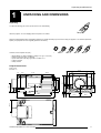
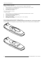

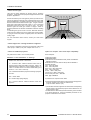

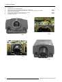
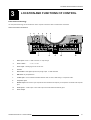


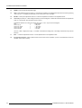
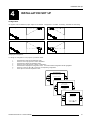
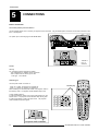
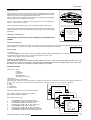
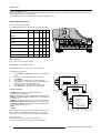
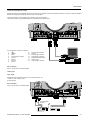

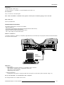


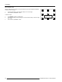
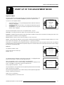
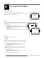
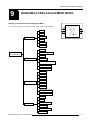
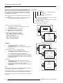
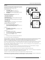

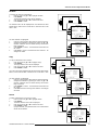
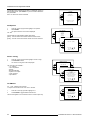
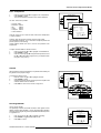
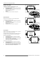
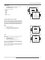
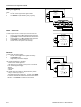
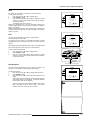
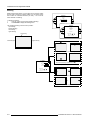
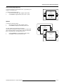
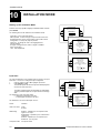

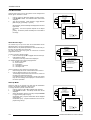
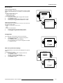
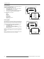


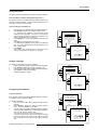
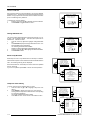
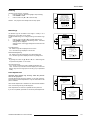
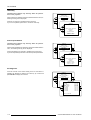
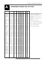
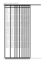


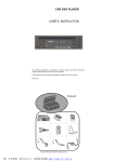
![Overview cPR67 and cPR84 [v00]](http://vs1.manualzilla.com/store/data/005648847_1-d158a5d3d4b92d14c7a3179652b88ffd-150x150.png)