1
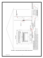
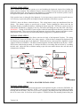
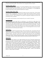
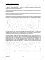
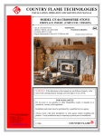
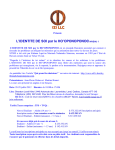
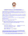
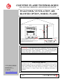
COUNTRY FLAME TECHNOLOGIES
INSTALLLATION, OPERATION, AND MAINTENANCE MANUAL
INGLENOOK VENTILATION AIR
BLOWER OPTION, MODEL IN-6200
INGLENOOK
CIRCUIT BREAKER
PANEL
RHEOSTAT
#1
#2
#4
#5
120V (BLACK WIRE)
#3
15A DUPLEX ELECTRICAL
RECEPTACLE
1. INSTALL RHEOSTAT ELECTRICAL BOX
PER CUSTOMER SPECIFIED LOCATION.
2. PULL WIRES FROM CIRCUIT BREAKER PANEL TO RHEOSTAT ELECTRICAL BOX.
GROUND (GREEN WIRE)
NEUTRAL (WHITE WIRE)
RHEOSTAT DETAIL
WIRES TO INGLENOOK
ELECTRICAL JUNCTION BOX
3. PULL BLACK WIRE BETWEEN INGLENOOK ELECTRICAL BOX & RHEOSTAT ELECTRICAL BOX.
4. INSTALL RHEOSTAT, COVER PLATE, RHEOSTAT CONTROL KNOB.
BLACK
BLACK
120V OUT
120V IN
120V, 15A (dedicated) CIRCUIT
FROM CIRCUIT BREAKER
PANEL
GROUND (GREEN WIRE)
NEUTRAL (WHITE WIRE)
5. WIRE INGLENOOK ELECTRICAL BOX/DUPLEX RECEPTACLE PER NATIONAL/LOCAL CODES.
6. CERTIFIED ELECTRICAN TO COMPLETE ALL ELECTRICAL WORK.
WARNING: If the Inglenook blower installation does not conform to
National Electrical Code, a shock hazard will result. This shock hazard
can be fatal under certain conditions. Use a certified electrician to
perform and ensure conformance to National and local codes.
FOR YOUR SAFETY
Country Flame Technologies
A Division of American Products, LLC
900 George Street
Marshfield, MO 65706
417-859-0990
417-859-0192
Installation and repair is to be performed by a qualified service person.
Improper installation and non-conformance to National and Local Codes can
create safety hazards and impact homeowner insurance. Contact a local
authorized dealer or Country Flame direct for additional information, if
required.
www.countryflame.com
© 2004
COUNTRY FLAME
TABLE OF CONTENTS
INTRODUCTION ..............................................................................................................................3
SAFETY INFORMATION ................................................................................................................3
INSTALLATION, GENERAL...........................................................................................................4
INSTALLATION, ELECTRICAL .....................................................................................................4
INSTALLATION, PREPARATION..................................................................................................4
INSTALLATION, STEP 1 .................................................................................................................7
INSTALLATION, STEP 2 .................................................................................................................7
INSTALLATION, STEP 3 .................................................................................................................7
INSTALLATION, STEP 4 .................................................................................................................8
INSTALLATION, FINAL STEP .......................................................................................................8
MAINTENANCE ...............................................................................................................................8
OPERATION......................................................................................................................................8
PROBLEMS .......................................................................................................................................8
PARTS ................................................................................................................................................9
LIMITED 1 YEAR WARRANTY ...................................................................................................10
Version 1.0b
2
INTRODUCTION
Congratulations on your purchase of an Inglenook fireplace system and thank you for purchasing the
optional IN-6200. Country Flame shares our customer’s concerns to protect the environment, obtain
value from their purchase, and we will be here to assist in any way possible over the coming years as
you enjoy the added benefits of the IN-6200 to your heating system.
This owner’s manual provides the necessary information to assure proper installation, proper
maintenance, and correct operation of an Inglenook IN-6200 blower option for the Inglenook fireplace.
The IN-6200 blower option was designed to enhance the operation of the Inglenook wood fuel system
or the Inglenook gas log system.
The IN-6200 enhances the natural convection design of the Inglenook by pulling cool room air into the
bottom of the Inglenook, increasing the temperature of this air, and then pushing this heated air back
into a home’s living space. By running the IN-6200 during normal Inglenook operation, room air
heating efficiency will be increased. Obviously, Inglenook users will benefit from the added warmth
and comfort whether it is the coldest winter day of the year or just when taking the chill off a room
during a cold rainy day.
Country Flame wishes you a lifetime of warmth and happiness.
SAFETY INFORMATION
-
Do not store or use gasoline or other flammables near any appliance.
-
Do not place clothing or flammable material on or near any heating appliance.
-
Children and adults should remain alert to the hazards of high surface temperatures, electrical
hazards, and moving parts associated with this appliance. Maintain safe clearances (stay away.)
-
Supervise young children playing in the same room wit an operating appliance.
-
INSTALLATION AND REPAIRS ARE TO BE COMPLETED BY A CERTIFIED
TECHNICIAN. A CERTIFIED PROFESSIONAL SHOULD INSPECT THIS APPLIANCE
BEFORE USE AND AT LEAST ANNUALLY.
-
The interior of a gas stove is subject to surface rust due to moisture in the combustion air as
well as condensation created during the initial warm up and firing of the gas appliance. At a
minimum, annually inspect this electrical device for any deterioration that may be due to
condensation.
-
WARNING: IMPROPER INSTALLATION, ADJUSTMENT, ALTERATION, SERVICE OR
MAINTENANCE CAN CAUSE INJURY OR PROPERTY DAMAGE. REFER TO THIS
MANUAL FOR ASSISTANCE OR FOR ADDITIONAL INFORMATION CONSULT A
QUALIFIED INSTALLER, SERVICE AGENCY, OR GAS SUPPLIER.
PLEASE KEEP THESE INSTRUCTIONS FOR FUTURE REFERENCE
Version 1.0b
3
INSTALLATION, GENERAL
Installation of the IN-6200 blower system is relatively simple, if a homeowner has planned for the
installation of the optional blower system during Inglenook installation. This means that a qualified
electrician should have already made all the necessary electrical connections between the home’s electrical
system and the Inglenook fireplace. The only thing left to do to install the IN-6200 is:
a)
install the dual blowers and electrical motor that is magnetically held in place,
b)
install the thermo disk provided with the kit that will be used to control the on/off cycles of
the blower system,
c)
install and make final connections to the wiring harness which have been greatly simplified
by the design of the wiring harness,
d)
finally, the last step is to plug the blower system into a properly grounded U.L. approved
duplex outlet that was provided for during the manufacturing of the Inglenook fireplace
system and should already be connected to the home’s electrical system.
INSTALLATION, ELECTRICAL
Installation of the IN-6200 blower system should take less than 30 minutes if a qualified electrician has
previously connected the Inglenook fireplace to the home’s electrical system. The Inglenook fireplace and
the Inglenook blower system must be electrically connected and grounded in accordance with local codes,
or in the absence of local codes, with the current NFPA 70 National Electric Code or in Canada, with CSA
C22.1 Canadian Electrical Code.
FIGURE 1 is a detailed drawing of the Inglenook electrical system installed in a typical home. A qualified
electrician should make all the necessary electrical connections during installation of the Inglenook
fireplace. Note that the IN-6200 blower speed control (rheostat) can be located on any wall that suits the
homeowner. Country Flame provides an electrical box for the rheostat; however, this part will not be
required if the electrician has already completed the wiring of the Inglenook as there should already be an
electrical box ready for the rheostat to be installed in. If all electrical connections to the fireplace are
complete, then installing the IN-6200 blower system is a “plug-n-operate” process.
INSTALLATION, PREPARATION
Unpack the IN-6200 kit and ensure that all parts have been included in the kit. Ensure that no shipping
damage has occurred. If shipping damage has occurred, notify the shipping agency immediately and notify
the local Country Flame Dealer where this product was purchased. The following items should be included
in the IN-6200 kit:
-
Blower motor with double squirrel cage blades and partial wiring harness
3 prong power cord (do not remove grounding pin), ready for connection to blower harness
1100F heat sensor
Rheostat, blower speed control
Rheostat control knob
Rheostat electrical box
Warning Label, (1) Caution, Electrical Hazard & (1) Warning, Inglenook Blower Only
Screws, (2) 12-24 by 3/8” Type F
Screws (2) 10-32 by 3/8” PMS
Screw (1) #6 by 3/8” PMS ground connection
Owner’s Manual; IN-6200 IOM Manual
The only tool that should be required for installation is a screwdriver or nut socket used to install the thermo
snap disk to the thermo snap disk mount and mount the rheostat.
Version 1.0b
4
FIGURE 1: HOUSE/INGLENOOK WIRING DIAGRAM
Version 1.0b
5
WOOD FRAMING
FRESH AIR INLET
ROMEX ELECTRICAL
CONNECTOR TO
ELECTRICAL BOX
LOCATED INSIDE
FIGURE 2: INGLENOOK ELECTRICAL CONNECTION
FIGURE 2 shows the proper location to bring electrical power to the Inglenook. Whether the Inglenook
blower system is to be immediately installed or planned as a later option, it is imperative that the electrical
supply be provided to the Inglenook fireplace during initial installation. Failure to install wiring during
installation will make future installation of a blower system more complex and expensive.
BLOWER
120 VOLT
AC 60HZ
21" BLACK WIRE
21" BLACK WIRE
MOLEX
PIN
FEMALE
FEMALE
SPADE
10" WHITE WIRE
EARTH
GROUND
MALE
SPADE
MALE
SPADE
110°F THERMO SNAP DISK
FIGURE 3: INGLENOOK BLOWER ELECTRICAL HARNESS
Version 1.0b
6
NEUTRAL
MALE
FEMALE
SPADE
GND
RIBBBED BLACK WIRE
GREEN WIRE
SMOOTH BLACK WIRE
MOLEX PIN PLUGS INTO MOLEX PLUG
INSTALLATION, STEP 1
Step 1 assumes that all electrical systems, up to and including the Inglenook electrical box holding the
duplex outlet are installed. This standard 15-ampere electrical outlet is located on the lower right side wall
behind the bottom grill. Previous pages of this manual cover installation of the electrical system or refer to
the Inglenook fireplace Owners Manual for additional information.
Fully open the lower air inlet grill of the Inglenook. It is not necessary to remove the lower grill; however,
it is necessary to protect the grill from damage during the installation of the blower system.
FIGURE 3 shows the blower electrical harness. This wiring harness comes pre-manufactured from the
factory. This harness requires no special tools to install. Before installing the blower unit into the
Inglenook fireplace, assemble the harness, including the thermo snap disk. The blower system can now be
tested before installation by plugging it into any wall outlet and heating the snap disk with a hair dryer.
WARNING: Testing of the blower system requires electrical knowledge that cannot be provided in this
instruction manual. There are moving parts and dangerous electrical voltages present in the blower system.
If the blower is to be tested, the power cord should only be plugged in by a qualified electrician.
INSTALLATION, STEP 2
FIGURE 4 shows how to install the blower unit into the body of the Inglenook Fireplace. The wiring
harness IS NOT shown in FIGURE 4 for clarity purposes. Slide the blower alongside the Inglenook Ash
Pan Housing towards the back of the Inglenook. Position the blower unit between the Inglenook’s frame
supports as shown in FIGURE 4. The blower unit has magnetic feet that will hold the unit in place. NOTE:
If the blower rattles during operation, it is because the blower is not sitting flat on the floor or is touching
the back wall. Adjust the unit to eliminate rattling or provide some cushion between the wall and unit to
eliminate noise vibration.
FIGURE 4: BLOWER INSTALLATION
INSTALLATION, STEP 3
Once the blower unit has been positioned at the back of the Inglenook fireplace as shown in FIGURE 4, the
snap disk can be mounted in its holder. NOTE: 2 sets of two screws each have been provided for mounting
the snap disk into its holder. Only one set of screws is required. Depending on the snap disk mount, either
the 10-32 screws or the 12-24 screws will be required. FIGURE 4 shows the mounting location along the
Version 1.0b
7
right side of the ash pan housing on the ceiling of the lower air inlet chamber. Utilize two of the screws
provided and mount the snap disk. All connections to the wiring harness should be complete.
INSTALLATION, STEP 4
Verify the wiring is not strained, damaged, or cut from the installation procedure. Ensure proper electrical
connections of all blower system components. Once verified, the 3-prong power cord can be plugged into
the electrical duplex outlet located on the right side of the lower air inlet chamber. It is recommended that
the main circuit breaker be turned off until all connections are complete.
INSTALLATION, FINAL STEP
Ensure that the blower circuit has been energized by turning on the main circuit breaker. Ensure that the
rheostat has been set to high speed. Using a hair dryer, heat the thermo snap disk up until the system has
energized. Once the Inglenook blower system test is complete, ensure all tools have been removed and
clean up the work area. Close the Inglenook lower grill unit verifying that no damage has occurred to the
grill during the blower installation.
Once installed, the IN-6200 blower system should provide years of trouble free operation.
MAINTENANCE
The IN-6200 blower system requires little or no maintenance. On a routine basis, a light wiping of the
lower compartment chamber will be required to remove dust that has been drawn into the chamber. On an
annual basis, the blower unit can be removed to clean the squirrel cage housings. Cleaning or light
vacuuming of the upper Inglenook chamber may be required on a semi-annual to annual basis. This will
require removing the screws from the upper grill in order to obtain access to the upper chamber. Cleaning
of the Inglenook will be a function of the amount of use, the amount of dust and debris in the home, and
depends greatly on the home’s main furnace filtration system. Clean the Inglenook as necessary to ensure
proper operation and avoid allowing dust to build up.
OPERATION
Electrical power is provided to the rheostat from the main circuit breaker panel. The rheostat controls the
Inglenook blower speed by controlling the amount of power delivered to the Inglenook blower motor.
Varying the rheostat control knob will increase or decrease the speed of the air being moved through the
Inglenook fireplace. The blower system will not operate until such time that a fire, in the Inglenook
firebox, has warmed the thermo snap disk above 1100F. Once the snap disk closes, the blower system
should begin to operate. The blower system will continue to operate, even after the Inglenook fire has gone
out. The blower continues to operate until the snap disk cools down and opens the electrical circuit.
PROBLEMS
The Inglenook blower system is a very simple electrical series circuit. This means electrical power
comes from the main circuit breaker panel to the rheostat, through the electrical duplex outlet,
through the snap disk, to the blower motor, and returns to the main circuit breaker panel. In the
event the blower system does not work, test the duplex outlet by plugging in a lamp, hair dryer,
vacuum cleaner or other household appliance that uses a standard 15-ampere outlet. If this
appliance works, then it tells the homeowner that the main circuit breaker panel, the rheostat, the
electrical outlet, and all wiring to these parts are good. If the household appliance fails to operate,
ensure that the main circuit breaker has not tripped. Whether the circuit breaker is or is not tripped
the remaining electrical circuit; snap disk and blower unit, will require a qualified electrician to
provide service in the event the system is still not operating properly. Contact a local authorized
dealer or Country Flame for assistance.
Version 1.0b
8
PARTS
The following list of parts is provided in the event service for the Inglenook blower system is required. All
parts listed in this manual may be ordered from an authorized local dealer or direct from Country Flame.
TABLE 1: BLOWER KIT, REPLACABLE PARTS LIST
PART
PART DESCRIPTION
PART NUMBER
Motor
Blower Unit w/partial wire harness
PP-1158
Cord
Power Cord, 3 prong harness
PP-04
Snap Disk
1100F Heat Sensor
PP-12
Rheostat
Speed Control Rheostat
PP-350
Knob
Rheostat Control Knob
PP-16
Box
Electrical Box
PP-05
Cover
Faceplate w/ 2 screws
PP-07
Label
Caution, Electrical Hazard
PP-486
Label
Warning, Inglenook Blower Only
PP-487
Screw
Screws, 2 each, 10-32 by 3/8” PMS
PP-142
Screw
Screws, 2 each 12-24 by 3/8” type F
PP-1310
Screw
Screw, 1 each #6 by 3/8” PMS Ground
PP-767
Manual
Owners Manual; In-6200 IOM Manual
PP-1168
Version 1.0b
9
LIMITED 1 YEAR WARRANTY
To establish the dates to which the Inglenook blower system’s limited 1-year warranty runs, the original
retail purchaser must mail a completed warranty card to Country Flame Technologies, 900 George Street,
Marshfield, MO 65706, within 60 days of the date of the blower system installation. If a homeowner fails
to mail in the warrant card, they will be required to prove the date of installation or the date of retail
purchase before warranty work can be performed.
The warranty exclusions and limitations of liability are effective upon installation of the blower system into
the Inglenook fireplace.
Subject to the conditions set forth herein, Country Flame Technologies extends the following warranty with
respect to Country Flame Inglenook blower system:
If Country Flame Technologies is reasonably satisfied that any part or portion of the Inglenook fireplace
blower system, covered by this Limited Warranty is defective in material or workmanship under normal use
and service as described in this operating instructions, Country Flame Technologies will take the following
action:
If the defect is reported during the first year from the date of installation, Country Flame
Technologies will replace or repair the defective components at its sole expense. The decision
whether to replace a component shall be made at Country Flame Technologies’ sole discretion.
This Limited Warranty does not cover components broken during shipping, misuse or careless
handling. Country Flame Technologies shall not be responsible for any indirect, incidental, or
consequential damages or for any costs other than those incurred by Country Flame Technologies
to repair or replace the defective component. If components other than factory-approved
components are used, all Country Flame Technologies warranty and liability on the Inglenook
blower system are immediately voided. Defects reported after the first year will not be
covered by warranty.
This Limited Warranty is the exclusive remedy available to the original retail customer. If Country Flame
Technologies cannot effectively resolve a warranty problem in an expedient and cost-effective manner, it
can discharge its entire warranty liability by refunding the price of the product to you.
This Limited Warranty, whether sold with the Inglenook fireplace or added thereafter, does NOT cover
products made by other manufacturers. The use of other unauthorized components immediately makes this
warranty null and void. This Limited Warranty is also void if a qualified installer in accordance with the
Installation Instructions does not install the Inglenook fireplace and blower system. Furthermore, the
Limited Warranty will be void if the Inglenook fireplace is not operated, at all times, according to the
Operating Instructions furnished with the fireplace. Authorized service representatives must perform
service work or the warranty is void.
EXCEPT TO THE EXTENT PROVIDED BY LAW, NO OTHER EXPRESS OR IMPLIED
WARRANTIES, INCLUDING WARRANTIES OF MERCHANTABILITY OR FITNESS FOR A
PARTICULAR PURPOSE, SHALL APPLY TO THIS FIREPLACE PRODUCT. In States that do not
allow limitations on how long an implied warranty lasts, or do not allow exclusion of indirect damages,
those limitations or exclusions may not apply. There may be additional rights not covered in this Limited
Warranty.
Country Flame Technologies reserves the right to make changes at any time, without notice, in design,
material, specifications and prices. Country Flame Technologies also reserves the right to discontinue
styles and products.
Version 1.0b
10