1
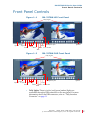
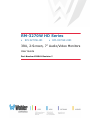
RM-3270W HD Series
•
RM-3270W-HD
• RM-3270W-2HD
3RU, 2-Screen, 7” Audio/Video Monitors
User Guide
Part Number 821041 Revision I
© 2013 Wohler Technologies, Inc. All rights reserved.
This publication is protected by federal copyright law. No part of this publication may be
copied or distributed, stored in a retrieval system, or translated into any human or computer
language in any form or by any means electronic, mechanical, manual, magnetic, or otherwise,
or disclosed to third parties without the express written permission of Wohler Technologies.
Reproduction
Licensed users and authorized distributors of Wohler Technologies, Inc. products may copy
this document for use with Wohler Technologies., Inc. products provided that the copyright
notice above is included in all reproductions.
Customer Support
Wohler Technologies, Inc.
31055 Huntwood Avenue
Hayward, CA 94544
www.wohler.com
Phone: 510-870-0810
FAX: 510-870-0811
US Toll Free: 1-888-596-4537
(1-888-5-WOHLER)
Web: www.wohler.com
Sales: [email protected]
Support: [email protected]
Disclaimers
Even though Wohler Technologies, Inc. has tested its equipment and software, and reviewed
the documentation, Wohler Technologies, Inc. makes no warranty or representation, either
express or implied, with respect to software, documentation, their quality, performance,
merchantability, or fitness for a particular purpose.
Wohler Technologies, Inc. reserves the right to change or improve our products at any time and
without notice.
In no event will Wohler Technologies, Inc. be liable for direct, indirect, special, incidental, or
consequential damages resulting from any defect in the hardware, software, or its
documentation, even if advised of the possibility of such damages.
Some states do not allow the exclusion or limitation for incidental or consequential damages, so
the above exclusion or limitation may not apply to you.
Printing
This document is intended to be printed on a duplex printer, such that the copy appears on
both sides of each page. This ensures that all new chapters start on a right-facing page.
This document looks best when printed on a color printer since some images may be indistinct
when printed on a black and white printer.
Last Update
October 17, 2013
ii
Par t N um b er :
D o c u m e nt T i t le U s e r G u id e
© 2 0 1 3 Wo h l e r Tec h n o l o g i e s , I n c. A l l r i g h t s r e s er ve d .
RM-3270W HD Series
User Guide
Introduction
Overview
The 3RU rack-mounted RM-3270W HD Series monitors set a new
standard in LCD monitors for broadcast and professional video
applications. It provides two 7”, 800 x 480 resolution, anti-glare TFT
screens. All video formats are scaled to fit on screen in the highest
quality using full, digital processing, precision scaling and gamma
correction to produce the best images available.
Topics
Topics
Introduction
Page
1
Safety Instructions
2
Installation Recommendations
3
FCC Compliance
3
Features
4
Specifications
5
Front Panel Controls
6
Rear Panel Connectors
9
On-Screen Display Features
11
Using the OSD Menu
12
Technical Functional Overview
19
8 2 1 7 0 4 : H D C C- 2 0 0 A ( 6 0 8 / 7 0 8 ) Us e r G u i d e
© 2 0 1 3 Wo h l e r Tec h n o l o g i e s, I n c. A l l r i g h t s r e s er ved .
1
RM-3270W HD Series User Guide
S a f e t y I n s tr u c ti o n s
Safety Instructions
I M P O R T AN T :
1.
Read, keep, and follow all of these instructions; heed all warnings.
2.
Do not use this equipment near water.
3.
Use only a dry cloth to clean the equipment.
4.
Do not block any ventilation openings. Install only in accordance
with the instructions in the section entitled, “Installation
Recommendations” on page 3.
5.
Do not install near any heat source such as a radiator, heat register,
amplifier, or stove.
6.
Do not expose the equipment to rain or moisture.
7.
Do not attempt to plug the unit into a two-blade outlet (with only
two prongs of equal width).
By design, these monitors will only plug into a three-prong outlet for
your safety. If the plug does not fit into your outlet, contact an
electrician to replace the obsolete outlet.
8.
Protect the power cord from being walked on or pinched,
particularly at plug’s source on the equipment and at the socket.
9.
Use only the attachments/accessories specified by the
manufacturer.
10. Unplug the equipment during lightning storms or when unused
for long periods of time.
11. Refer all servicing to qualified service personnel. Servicing will be
required under all of the following conditions:
2
Par t N um b er :
•
The equipment has been damaged in any way, such as when
the power-supply cord or plug is damaged.
•
Liquid had been spilled or objects have fallen onto the
equipment.
•
The equipment has been exposed to rain or moisture.
•
The equipment does not operate normally.
•
The equipment has been dropped.
D o c u m e nt T i t le U s e r G u id e
© 2 0 1 3 Wo h l e r Tec h n o l o g i e s , I n c. A l l r i g h t s r e s er ve d .
RM-3270W HD Series User Guide
I n s ta l la t i o n R e c o m me n d a t io n s
Installation Recommendations
Mounting
The unit is designed to install into a standard 19” rack. The unit should
be mounted at approximately eye level for optimum visual
observation.
Heat Dissipation
No special physical mounting considerations are necessary regarding
heat dissipation except under adverse conditions, provided the
ambient temperature inside the mounting enclosure does not exceed
40°C (104°F). Adjacent devices can be rack mounted (or stacked)
in proximity to the unit. If the temperature is above 40°C, allow
a 1RU (1.75”/44.45mm) space above and below the unit for air
circulation.
DC Power
Connect the unit to its external 100 to 240VAC (50 to 60Hz) to 12VDC
power supply (included).
FCC Compliance
This equipment has been tested and found to comply with the limits for
a Class A digital device, pursuant to part 15 of the FCC Rules. These
limits are designed to provide reasonable protection against harmful
interference when the equipment is operated in a commercial
environment. This equipment generates, uses, and can radiate radio
frequency energy and, if not installed and used in accordance with the
instruction manual, may cause harmful interference to radio
communications. Operation of this equipment in a residential area is
likely to cause harmful interference in which case the user will be
required to correct the interference at his own expense.
8 2 1 7 0 4 : HD C C- 2 0 0 A ( 6 0 8 / 7 0 8 ) U s e r G u i d e
© 2 0 1 3 Woh l er Te c h n o l o g i es , I n c . A ll r i g h t s r e se r ve d .
3
RM-3270W HD Series User Guide
Features
Features
The RM-3270W HD Series audio/video monitors are designed for
confidence monitoring of composite video broadcast signal video
sources. HD and 2HD models also monitor SDI signals. Input signals
are automatically detected and displayed. Four to eight audio channels
per screen may be selected for visual monitoring on bar graph style
level meters. A headphone jack allows audible stereo monitoring of the
left/right channels on all models. Both models have stereo speakers.
Each of the two high-resolution LCD screens display either 4:3 or 16:9
aspect ratio. Parameters are selected and adjusted using an On Screen
Display (OSD) MENU. A DB9 connector serves as the interface to the
two tally lights on the front panel.
Additional overlays can be added by the operator for safe area and safe
title markers, center mark, and display name.
The slim and light weight design provides two screens in a very
compact rack-size (3RU) while the chassis only has 2.5 inches of depth.
The feature-rich RM-3270W HD Series monitors provide all of the
following:
• Two LCDs, 7” diagonal each
• Selectable 16:9 or 4:3 screen aspects for on screen video
• Rack mount mechanical design with vertical tilt
• Audio level meter display for up to eight channels per display
• Monitor audio source from selected display on stereo headphones
• Visually monitor audio levels on meters assignable to any channel
• Level meters can display VU, PPM (PK) or both with assignable
-20db to -18db level
• Local control (via menu operation) for all functions including:
4
Par t N um b er :
•
Blue gun as mono
•
Safe area
•
Safe title
D o c u m e nt T i t le U s e r G u id e
© 2 0 1 3 Wo h l e r Tec h n o l o g i e s , I n c. A l l r i g h t s r e s er ve d .
RM-3270W HD Series User Guide
S p e ci f i c a t i o n s
•
Center markers
•
Monochrome display mode
•
Over/underscan
•
Display of input format
•
Waveform or vectorscope
•
Display of up to 10 characters of user-defined text
•
Red/green/yellow/white text color
•
Built in color bars 75% full field
•
User defined configuration
•
Auto sets at power up
Specifications
Table 1–1
RM-3270W-HD/2HD Specifications
Specification
HD
Number of Screens
Display
Aspect Ratios
Active Viewing
Area
Screen Treatments
Viewing Angles
(Tilt)
Screen Colors
Resolution
(Dots, H x V)
Dot Pitch
(H x V, mm)
Pixel Response (ms)
Luminance
Contrast
Chromacity
Color Temperature
2HD
2 active color matrix amorphous 7”
LCD TFT screens
7” diagonal
4:3 or 16:9
6” H x 3.46” V (152 mm H x 88 mm V)
Anti-glare 4H hardness
135°H x 110°V
16.7 million
800 x 480
0.1905 x 0.1905
<16 typical
350 cd/m2
700:1
72% CIE 1931 color gamut
D65
8 2 1 7 0 4 : HD C C- 2 0 0 A ( 6 0 8 / 7 0 8 ) U s e r G u i d e
© 2 0 1 3 Woh l er Te c h n o l o g i es , I n c . A ll r i g h t s r e se r ve d .
5
RM-3270W HD Series User Guide
S p e c if i c a ti o n s
Table 1–1
RM-3270W-HD/2HD Specifications
(Continued)
Specification
Space Required
Dimensions
(W x H x D)
Shipping Weight
Power
Consumption
Operating
Temperature
Video Format
Inputs (per screen)
Outputs (per
screen)
HD
3 RU
19.1” x 5.25” x 2.6” (486 x 133 x 67 mm)
9 lbs. (4.08 kg)
12VDC/10 watts (3.8 Amps max) CE & UL
power supply
0°C (32°F) to 40°C (104°F)
All HD/SD-SDI and CVBS
1 HD/SD-SDI, Analog 2 HD/SD-SDI, Analog
Composite (BNC)
Composite (BNC)
1 Pair Analog Audio
(RCA)
1 HD/SD-SDI
Re-clocked (BNC)
1 Pair Analog Audio
(RCA)
Supplied
Accessories
Note:
6
Par t N um b er :
2HD
2 Pair Analog Audio
(RCA)
None
AC power adapter
All of the specifications listed above are subject to change
without notice.
D o c u m e nt T i t le U s e r G u id e
© 2 0 1 3 Wo h l e r Tec h n o l o g i e s , I n c. A l l r i g h t s r e s er ve d .
RM-3270W HD Series User Guide
Front Panel Controls
Front Panel Controls
Figure 1–1
RM-3270W-HD Front Panel
Tally Lights
Power
Speaker Aspect
Scan
F Keys
Menu
Headphone Jack
Enter
Mute LCD Screen
Blue
Figure 1–2
Speaker
RM-3270W-2HD Front Panel
Tally Lights
Power
Speaker In A/B
User Keys
Menu
Scan
Headphone Jack
Enter
Mute LCD Screen
Blue
Speaker
• Tally Lights: These tri-color (red/green/amber) lights are
controlled through a DB9 connector on the rear panel. For more
information about the DB9 connector, refer to “Tally Interface
Connector” on page 11.
8 2 1 7 0 4 : HD C C- 2 0 0 A ( 6 0 8 / 7 0 8 ) U s e r G u i d e
© 2 0 1 3 Woh l er Te c h n o l o g i es , I n c . A ll r i g h t s r e se r ve d .
7
RM-3270W HD Series User Guide
Front Panel Controls
• Speakers: Audio may be selected for monitoring through the left
and right speakers.
Note:
The left LCD must be turned on for audio to function
from either the left or the right screen, because the
audio amplifiers are powered from the left LCD.
Therefore, if only one screen is to be used, be certain
that it is the left one.
• Power: Each of the two Power buttons turn the associated LCD
screen on and off; the LED glows green to indicate on. When the
indicator above the power switch is green then the unit is receiving
power. When the indicator is flashing, the unit is in stand-by mode.
• In A/B: These two buttons switch between signal inputs.
Note:
The In A/B buttons are only available on the 2HD.
• Scan: The Scan button toggles between the full video signal view
(underscan mode) to a typical display visible on a customer’s
monitor (normal mode). The LED glows green to indicate
underscan.
• Aspect: This button toggles the aspect ratio between 4:3 and 16:9
for the associated LCD screen. It has no affect on HD widescreen
formats.
Note:
The Aspect button is not available on the
RM-3270W-2HD.
• User 1 through User 3 or F1 though F3: The User/F buttons are
programmable as hot keys for parameter adjustments.
• Menu: Press this button to display the OSD MENU. See Using the
OSD Menu on page 12 for more details.
• Blue/Down: The Down function is on the same button as the
Blue function. When the OSD MENU is displayed, this button
navigates down through the menu and sub-menu selections. When
the OSD MENU is not displayed, pressing this button initiates Blue
mode.
8
Par t N um b er :
D o c u m e nt T i t le U s e r G u id e
© 2 0 1 3 Wo h l e r Tec h n o l o g i e s , I n c. A l l r i g h t s r e s er ve d .
RM-3270W HD Series User Guide
Front Panel Controls
• Mute/Up: The Up function is on the same button as the Mute
function.When the OSD MENU is displayed, this button navigates
up through the menu and sub-menu selections. When the OSD
MENU is not displayed, pressing this button controls audio
selection.
Note:
The left LCD must be turned on for audio to function
from either the left or the right screen, because the
audio amplifiers are powered from the left LCD.
Therefore, if only one screen is to be used, be certain
that it is the left one.
• Enter: When the OSD MENU is displayed, pressing this button
accepts selections in the menus and sub-menus. When the OSD
MENU is not displayed, the button cycles through volume and
image controls.
• Headphone Jack: Monitor the assigned left/right stereo audio
channels with stereo headphones from this mini-stereo connector.
• LCD Screen: The LCD screens display the audio meters, menus,
and OSD features over the video.
8 2 1 7 0 4 : HD C C- 2 0 0 A ( 6 0 8 / 7 0 8 ) U s e r G u i d e
© 2 0 1 3 Woh l er Te c h n o l o g i es , I n c . A ll r i g h t s r e se r ve d .
9
RM-3270W HD Series User Guide
R e a r P a n e l C o n n e ct o r s
Rear Panel Connectors
Rear Panel Connectors for the RM-3270W-HD
Figure 1–3
Video Input
HD/SD-SDI Output
RM-3270W-HD Rear Panel
Tally Lights Interface Power
RS-485 I/O
Audio Outputs (L & R)
Audio Inputs (L & R)
• Video Input: This auto-detecting, input connector accepts HD/SDSDI or analog CVBS video signals. The inputs comply with
SMPTE259M, SMPTE292M/ITU-R BT601. Composite video inputs
comply with SMPTE-170M.
• HD/SD-SDI Output: The system re-shapes and re-clocks an HD/
SD-SDI signal before outputting it to this female BNC connector.
• RS-485 I/O (on RJ-45): These two ports are used for system
software upgrades and dynamic IMD controls.
10
Par t N um b er :
D o c u m e nt T i t le U s e r G u id e
© 2 0 1 3 Wo h l e r Tec h n o l o g i e s , I n c. A l l r i g h t s r e s er ve d .
RM-3270W HD Series User Guide
Rear Panel Connectors
Figure 1–4
RS-485 I/O Pin-Out
Table 1–2
Pin
1, 2
3
4
5
6
7, 8
RS-485 Pin-Out
RS485 In terminal
GND
TxRx+
RxTx+
NC
RS485 Out Terminal
GND
TxRx+
RxTx+
NC
• Analog Audio Input: Input terminals for the analog audio signal.
L: left audio channel; R: right audio channel.
• Analog Audio Output: Output terminals of the analog audio signal.
L: left audio channel; R: right audio channel.
Rear Panel Connectors for the RM-3270W-2HD
Figure 1–5
Audio Inputs
Video Inputs
RM-3270W-2HD Rear Panel
RS-485 I/O
Power
Tally Lights Interface
8 2 1 7 0 4 : HD C C- 2 0 0 A ( 6 0 8 / 7 0 8 ) U s e r G u i d e
© 2 0 1 3 Woh l er Te c h n o l o g i es , I n c . A ll r i g h t s r e se r ve d .
11
RM-3270W HD Series User Guide
On-Screen Display Features
Common Connectors
• Power Connector: To provide power to the unit, attach the supplied
100 to 240VAC to 12VDC power supply to this connector.
• Tally Interface Connector: This DB9 connector controls the tally
lights on the front panel. Refer to Figure 1–6 below for the pin out.
Figure 1–6
Rear Panel DB9 Connector Pin Out
On-Screen Display Features
Figure 1–7
Display Features
Input Signal
Safe Areas
Center Marker
Audio Levels
IMD
Time Code
12
Par t N um b er :
D o c u m e nt T i t le U s e r G u id e
© 2 0 1 3 Wo h l e r Tec h n o l o g i e s , I n c. A l l r i g h t s r e s er ve d .
RM-3270W HD Series User Guide
Using the OSD Menu
• Input Signal: The input signal is automatically detected as vertical
active line count, (i)nterlaced or (p)rogressive, and frame rate in Hz.
• Audio Levels: Levels for the audio channels are displayed on up to
eight meters as left/right pairs: maximum of four meters on the left
side and four on the right.
• IMD: The OSD MENU provides settings to customize the IMD (In
Monitor Display) text area to show a line of characters, numbers,
and some symbols.
• Time Code: The de-embedded time code from the HD/SD-SDI
source displays in the bottom right corner.
Using the OSD Menu
A description of how to use the OSD MENU follows. Also refer to Table
1–3 on page 13 for typical values and domain ranges.
1.
Press the Menu button to display the menu.
Note:
If you do not press another button for approximately 30
seconds, the menu will disappear from the screen.
2.
Use the Up and Down buttons to navigate through the submenus.
3.
Press the Enter button to enter the parameter selections in the
chosen submenu.
4.
Use the Up or Down buttons to cycle through the submenu
selections.
5.
When the desired option is highlighted, press the Enter button to
select it.
6.
Use the Up or Down buttons to adjust the parameter value up or
down, make a selection, or turn a function on or off.
7.
Press the Menu button to back out of a parameter or submenu.
Press the Menu button again to remove the menu from the screen.
8 2 1 7 0 4 : HD C C- 2 0 0 A ( 6 0 8 / 7 0 8 ) U s e r G u i d e
© 2 0 1 3 Woh l er Te c h n o l o g i es , I n c . A ll r i g h t s r e se r ve d .
13
RM-3270W HD Series User Guide
U s i n g th e O S D M e n u
Table 1–3
RM-3270W-HD and RM-3270W-2HD OSD Menu
Structure
Menu
STATUS
Parameters
Default
Value
FORMAT
N/A
COLOR TEMP
D65
MON SOURCE
N/A
SCAN
UNDER
SCAN
SD ASPECT
4:3
MODEL
RM3270WHD
CONTRAST
VIDEO
Not configurable, signal dependent
-116 through 139
BRIGHTNESS
SATURATION
Domain Range
000
-128 through 127
SHARPNESS
000 through -15
HUE
-032 through 031
RESET
YES
COLOR TEMP
D65
Loads system defaults
• D65
•
D56
•
D95
•
USR
R GAIN
G GAIN
B GAIN
R OFFSET
128
0 through 255
YES
Loads system defaults
G OFFSET
B OFFSET
RESET
14
Par t N um b er :
D o c u m e nt T i t le U s e r G u id e
© 2 0 1 3 Wo h l e r Tec h n o l o g i e s , I n c. A l l r i g h t s r e s er ve d .
RM-3270W HD Series User Guide
Using the OSD Menu
Table 1–3
Menu
RM-3270W-HD and RM-3270W-2HD OSD Menu
Structure (Continued)
Parameters
AUDIO MON
MON SOURCE
AUDIO
Default
Value
ON
MET 1
Domain Range
ON
•
MET 1
•
MET 2
•
MET 3
•
MET 4
VOLUME
-30db
-30 db through 0 db
METER SIZE
SMALL
Not Configurable
000
000 through 255
-20 DB
-20DB or -18DB
• VU
METER H POS L
METER H POS R
TEST LEV
IN A:MET 1
IN A:MET 2
IN A:MET 3
IN A:MET 4
VU+PK
•
PK
•
VU+PK
•
NONE
8 2 1 7 0 4 : HD C C- 2 0 0 A ( 6 0 8 / 7 0 8 ) U s e r G u i d e
© 2 0 1 3 Woh l er Te c h n o l o g i es , I n c . A ll r i g h t s r e se r ve d .
15
RM-3270W HD Series User Guide
U s i n g th e O S D M e n u
Table 1–3
Menu
RM-3270W-HD and RM-3270W-2HD OSD Menu
Structure (Continued)
Parameters
Default
Value
IN A:MET 1-L
CH 1
IN A:MET 1-R
CH 2
IN A:MET 2-L
CH 3
IN A:MET 2-R
CH 4
IN A:MET 3-L
CH 5
IN A:MET 3-R
CH 6
IN A:MET 4-L
CH 7
IN A:MET 4-R
CH 8
Domain Range
EBD1 through EBD16
Note: The IN B options are only available on the 2HD model.
AUDIO
(Continued)
IN B:MET 1
IN B:MET 2
IN B:MET 3
VU+PK
IN B:MET 4
IN B:MET 1-L
CH 1
IN B:MET 1-R
CH 2
IN B:MET 2-L
CH 3
IN B:MET 2-R
CH 4
IN B:MET 3-L
CH 5
IN B:MET 3-R
CH 6
IN B:MET 4-L
CH 7
IN B:MET 4-R
CH 8
•
VU
•
PK
•
VU+PK
•
NONE
EBD1 through EBD16
ON or OFF; toggles audio enable
MARKER
16
Par t N um b er :
SAFE MARKER
OFF
CENTER
OFF
90%
OFF
80%
OFF
between the two monitors, (i.e.,
enabling the ON selection on one
turns the other OFF).
ON or OFF
D o c u m e nt T i t le U s e r G u id e
© 2 0 1 3 Wo h l e r Tec h n o l o g i e s , I n c. A l l r i g h t s r e s er ve d .
RM-3270W HD Series User Guide
Using the OSD Menu
Table 1–3
Menu
RM-3270W-HD and RM-3270W-2HD OSD Menu
Structure (Continued)
Parameters
Default
Value
Domain Range
• 2.35:1
Marker
(Continued)
AREA MARKER
OFF
STD DISP
WFM/VT DISP
OFF
•
1.85:1
•
15:9
•
14:9
•
13:9
•
4:3
•
•
OFF
AUTO OFF
•
ON
•
•
OFF
VECTOR
•
WFM
•
OFF
TC DISP
UMD (IMD: In
ON or OFF
Monitor Display)
OSD
DISP
OSD TLY DISP
OSD TLY MODE
LED TLY DISP
ON
RGY
ON
ON or OFF
• RG
•
GR
•
RGY
•
T1T2
•
T2T1
•
T1-
•
T2-
ON or OFF
8 2 1 7 0 4 : HD C C- 2 0 0 A ( 6 0 8 / 7 0 8 ) U s e r G u i d e
© 2 0 1 3 Woh l er Te c h n o l o g i es , I n c . A ll r i g h t s r e se r ve d .
17
RM-3270W HD Series User Guide
U s i n g th e O S D M e n u
Table 1–3
RM-3270W-HD and RM-3270W-2HD OSD Menu
Structure (Continued)
Menu
Parameters
—
COLOR
ALIGN
Default
Domain Range
Value
UMD FIXED SET UP
N/A
WHITE
A user-definable input string of up to
16 alphanumeric characters (also
includes some symbols)
•
RED
•
GREEN
•
YELLOW
•
•
WHITE
LEFT
CENTER •
CENTER
• RIGHT
UMD PROTOCOL
• LOCAL
—
OSD
(Continued)
•
IMAGE VIDEO
•
TSL V4.0
•
TSL V3.1,
UMD ID
000
000 through 255
UMD NAME (S/N)
—
N/A
UMD TLY MODE
T1T2
A user-definable input string of up to
16 alphanumeric characters (also
includes some symbols)
•
T2
•
T1
•
T2T1-
• T1T2UMD BAUD RATE
• 2400
—
18
Par t N um b er :
N/A
•
4800
•
9600
•
19200
•
38400
•
57600
•
115200
D o c u m e nt T i t le U s e r G u id e
© 2 0 1 3 Wo h l e r Tec h n o l o g i e s , I n c. A l l r i g h t s r e s er ve d .
RM-3270W HD Series User Guide
Using the OSD Menu
Table 1–3
RM-3270W-HD and RM-3270W-2HD OSD Menu
Structure (Continued)
Menu
Parameters
Default
Domain Range
Value
TALLY SOURCE
• STANDARD
OSD
(Continued)
USER
CONTROL
USER
CONFIG
—
N/A
SCAN
NORMA
L
SD ASPECT
4:3
H/V DELAY
OFF
•
TSL
•
STANDARD+IV422
•
IMAGE VIDEO 422
•
IMAGE VIDEO HW
NORMAL or UNDER SCAN
4:3 or 16:9
• OFF
•
H
•
V
•
H/V
COLOR BAR
DISABL
E
VECTOR REF
75% CB 75% CB or 100% CB
OSD CONTROL
ON
WFM/VT MODE
SOLID
USER1
USER2
USER3
DISABLE or “ON”
ON or OFF
• SOLID
•
75%
•
50%
• 25%
H/V
• MON SOURCE
DELAY
• OSD CONTROL
SD
ASPECT • AREA MARKER
WFM
DISPLAY
• SAFE MARKER
•
WFM DISPLAY
•
SD ASPECT
• H/V DELAY
8 2 1 7 0 4 : HD C C- 2 0 0 A ( 6 0 8 / 7 0 8 ) U s e r G u i d e
© 2 0 1 3 Woh l er Te c h n o l o g i es , I n c . A ll r i g h t s r e se r ve d .
19
RM-3270W HD Series User Guide
Technical Functional Overview
Technical Functional Overview
Figure 1–8 on page 19 and Figure 1–9 on page 20 illustrate the overall
functionality of the RM-3270W HD Series monitors.
Figure 1–8
RS-485
Out
RM-3270W-HD Block Diagram
LED
(UMD, OSD Tally,
Programming)
RS-485
In
Left
Speaker
L
R
Audio In
Audio Out
20
Par t N um b er :
D o c u m e nt T i t le U s e r G u id e
© 2 0 1 3 Wo h l e r Tec h n o l o g i e s , I n c. A l l r i g h t s r e s er ve d .
Stereo
Audio Amp
Right
Speaker
RM-3270W HD Series User Guide
T e c h n i c a l F u n c t i o n a l O v e r vi e w
Figure 1–9
RS-485
Out
RS-485
In
RM-3270W-2HD Block Diagram
(UMD, OSD Tally,
Programming)
Stereo
Audio Amp
8 2 1 7 0 4 : HD C C- 2 0 0 A ( 6 0 8 / 7 0 8 ) U s e r G u i d e
© 2 0 1 3 Woh l er Te c h n o l o g i es , I n c . A ll r i g h t s r e se r ve d .
21
RM-3270W HD Series User Guide
Technical Functional Overview
22
Par t N um b er :
D o c u m e nt T i t le U s e r G u id e
© 2 0 1 3 Wo h l e r Tec h n o l o g i e s , I n c. A l l r i g h t s r e s er ve d .