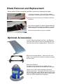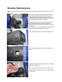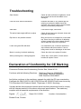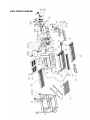
1
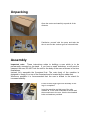
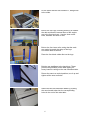
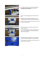
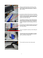
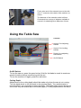
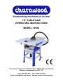
10” TABLE SAW
OPERATING INSTRUCTIONS
MODEL: W616
Charnwood, Cedar Court, Walker Road, Hilltop Industrial Estate,
Bardon, Leicestershire, LE67 1TU
Tel. 01530 516 926 Fax. 01530 516 929
email: [email protected] website: www.charnwood.net
1
GENERAL SAFETY RULES
WARNING: Do not attempt to operate the machine until you have read thoroughly
and understood completely all instructions, rules, etc. contained in this manual.
Failure to comply may result in accidents involving fire, electric shock, or serious
personal injury. Keep this owner's manual and review frequently for continuous safe
operation.
1. Know your machine. For your own safety, read the owner's manual
carefully. Learn its application and limitations, as well as specific
potential hazards pertinent to this machine.
2. Make sure all tools are properly earthed.
3. Keep guards in place and in working order. If a guard must be
removed for maintenance or cleaning, make sure it is properly
replaced before using the machine again.
4. Remove adjusting keys and spanners. Form a habit of checking to
see that the keys and adjusting spanners are removed from the
machine before switched it on.
5. Keep your work area clean. Cluttered areas and workbenches
increase the chance of an accident.'
6. Do not use in dangerous environments. Do not use power tools in
damp or wet locations, or expose them to rain. Keep work areas well
illuminated.
7. Keep children away. All visitors should be kept a safe distance
8. from the work area.
9. Make workshop childproof. Use padlocks, master switches
and remove starter keys.
10. Do not force the machine. It will do the job better and be safer at
the rate for which it is designed.
11. Use the right tools. Do not force the machine or attachments to do a job
for which they are not designed. Contact the manufacturer or distributor
if there is any question about the machine's suitability for a particular
task.
2
12. Wear proper apparel. Avoid loose clothing, gloves, ties, rings, bracelets,
and jewellery which could get caught in moving parts. Non-slip footwear is
recommended. Wear protective hair covering to contain long hair.
13. Always use safety glasses. Normal spectacles only have impact resistant
lenses. They are not safety glasses.
14. Do not over-reach. Keep proper footing and balance at all times.
15. Maintain the machine in good condition. Keep the machine clean for best and
safest performance. Follow instructions for lubrication and changing
accessories.
16. Disconnect the machine from power source before servicing and when
changing the blade.
17. Never leave the machine running unattended. Turn the power off. Do not
leave the machine until it comes to a complete stop.
18. Do not use any power tools while under the effects of drugs, alcohol or
medication.
19. Always wear a face or dust mask if operation creates a lot of dust and/or
chips. Always operate the tool in a well ventilated area and provide for proper
dust removal. Use a suitable dust extractor.
ADDITIONAL RULES FOR CIRCULAR SAWS
1. Ensure that the saw table is clear of off-cuts, tools or anything else that might
foul the work-piece.
2. If your saw has a dust extractor hose connected to the crown guard, ensure
that it is held clear of the table and will not foul the work-piece as it passes
over the table.
3. When cutting large sheets of material or long boards use one or more roller
stand(s) to support the work or have a competent helper to support it as it
feeds off the rear of the table.
4. Never use the saw without the riving knife and check that it is in line with the
blade before using the saw.
5. Always use a brush to clear the table of dust or debris. NEVER use your
hands, especially when the machine is running.
6. ALWAYS USE A PUSH STICK WHEN IT IS NECESSARY TO PUSH ANY
PIECE OF MATERIAL OF SUCH SIZE THAT IT WOULD BRING YOUR
HANDS WITHIN 30 CM OF THE BLADE.
3
7. Do not cut material that is badly warped or which has screws or nails in it
8. Be extra vigilant when cutting stock which has loose knots in it as these may
fly out of the saw.
9. NEVER remove the table insert when the saw is running.
10. To avoid exposure to hazardous dust, do not use this saw without connecting
it to a suitable dust extractor.
11. Always work with a sharp saw blade and feed the work at a rate suited to the
thickness and hardness of the material.
Note: This table saw has been designed and built solely as a woodworking machine.
Do not modify it in any way or use for anything other than its designated
purpose. Neither the manufactures nor the supplies are liable for any damage
or injury caused by incorrect assembly, operation or electrical connection of
this machine.
Important:
Risk of Injury!
Never reach into
the running saw blade.
Wear Eye
Protection
Wear Ear
Protection
Specification
Table size
Table size with extensions
Table height
Motor (carbon brush)
Blade diameter and bore
Blade rotation speed (no load)
Maximum depth of cut at 90o/45 o
Cutting width with table extension
Dust extractor hose connection
Noise emission LPA Idle
Weight
Manufacturers Free Warranty
Rating
440(w) x 660(d) mm
950(w) x 1060 (d) mm
830mm
1800W (2.5 hp), 240v single phase
254mm (10”) x 30mm
5700 rpm
75/60mm
450mm (17”)
40mm
93.2dB(A)
39 kg
1 year
Hobby
Rating Description
Hobby: Suitable for Weekend DIY'ers and woodworking enthusiasts.
Generally lighter weight machines with lower power ratings and smaller tooling capacities.
Typically only ever used by one person for short periods of time or longer periods of time
infrequently. Machinery should be well maintained in a clean, dry environment such as a
home workshop, garage or timber shed. Expected maximum use of 100 hours annually.
Please Note: Using a product in excess of its rating will void the manufacturers free
warranty.
4
Unpacking
Open the carton and carefully unpack all of the
contents.
Familiarise yourself with the parts and take the
time to sort out the various types of nuts and bolts.
Assembly
Important note: These instructions relate to building a saw which is to be
permanently mounted on its stand. If you have a small workshop, or will need to
transport the saw, DO NOT bolt the rails to the body of the saw as shown in first two
illustrations.
Instead, fully assemble the floorstand first. The main body of the machine is
designed to simply fit on top of the floorstand and is located by the rubber feet.
Whenever possible it is recommended that the saw is bolted to the stand for
increased stability.
Leave all bolts finger tight until assembly of the
legs is completed.
Invert the machine and bolt one of the rails
marked ‘B’ to the front underside as shown and
the second one to the rear. Use the hex headed
bolts and washers provided.
5
Do the same with the rails marked ‘A’, fitting these
to the sides.
Bolt on the four legs, ensuring that they fit outside
the rails and that the narrow faces of the angles
are to the front and rear. Use the short coach
bolts, washers and nuts for this.
Bolt on the four lower rails, noting that the ends
are angled to match the splay of the legs.
Use coach bolts as before.
Place the four black rubber feet on the legs.
Bolt the two stabilisers to the back legs. These
prevent the possibility of the table tipping if a
heavy board is resting on the rear extension table.
Return the saw to a vertical position, true it up and
tighten all the nuts and bolts.
Attach the two side extension tables by pushing
the round metal tubes into the corresponding
holes in the end of the main table.
6
The side extensions are locked in place with the
four large, black knobs which screw into the
underside of the main table.
Bolt the two blue support arms to the back of the
saw.
Loosely screw two bolts with washers into the
threaded holes in the back edge of the main table.
Loosely fit bolts, washers and nuts into the top end
of the blue support arms.
Fit the slots in the rear extension table over the
heads of the bolts.
Use a straight edge or the fence extrusion to level
the rear extension table. The surface should be
flush to the main table.
Put the push stick in its holder, on the right hand
side of the saw but please do not leave it there!
Use it whenever a cut will bring your fingers closer
than 30cm from the blade.
7
Remove the bolt and wing nut from the crown
guard and fit the guard over the top of the riving
knife. Replace the bolt and wing nut. Tighten
them securely.
Lay the blue section of the rip fence on the table.
Using two long coach bolts, fit the thin metal guide
bar to it, as shown and then slide the aluminium
section over the guide bar. Screw a wing nut with
washer onto each coach bolt.
The aluminium extrusion is shown fitted with the
taller side facing the blade. When cutting narrow
and thin timber, the extrusion can be rotated 90
degrees clockwise to avoid it fouling on the saw
guard.
Fit the fence to the guide rail which runs along the
front of the table. It can be locked in place with
the locking handle.
There is a magnifier to assist you with setting the
fence.
The sliding mitre fence is assembled in a similar
manner, using the remaining guide bar and two
short coach bolts and wing nuts.
Fit one end of the hose to the crown guard.
8
Fit the other end of the extractor hose to the side
of the T connector at the back of the machine, as
shown.
The diameter of the extraction outlet is 40mm.
Charnwood has a range of adaptors available to
convert it for attaching other diameters of hose.
Using the Table Saw
Controls
Angle of Cut Adjusting
Handle
T
Angle of Cut Locking
Handle
Depth of cut adjusting
Hand wheel
On/Off Switch
On/Off Switch
To turn the saw on, press the green button. Wait for the blade to reach its maximum
speed of rotation before commencing with the cut.
To turn the machine off again, press the red button.
Cutting Depth
Adjustments to the cutting depth should be made only when the saw is not running.
Turn the hand wheel to set the blade to the required depth. Turn anticlockwise to
raise the blade, turn clockwise to lower the blade. The blade height should always be
set so that only the carbide tips of the blade (approx. 5mm) projects above the wood.
9
Cutting Width
The rip fence is used to make longitudinal (with the grain) cuts. The fence can be
fitted on either side of the saw blade. Set the fence to the required dimension with
the help of the magnifier and scale. Clamp the fence in place by firmly pressing down
the eccentric lever.
To avoid kickback, the far end of the fence extrusion should be set correctly.
The fence extrusion should be set so that the end is level with the centre of the saw
blade. This allows the timber space to expand into, after the cut has been made.
When cutting wider pieces the fence extrusion can be moved further towards the
back of the blade, in a line projecting at roughly at 45 degrees out from the centre of
the blade.
Mitre Fence
To cut across the grain, use the sliding mitre fence. Insert the fence into one of the T
shaped slots in the table.
To set 90 degrees or any other angle, undo the locking knob and rotate the quadrant
to the desired angle. Lock the angle setting with the plastic knob. The mitre fence
can be used on either side of the blade.
If a longer fence is required, you can fit the extrusion from the rip fence onto the
mitre fence. When setting the fence, take care to ensure the fence will not contact
the blade.
Angle of Cut
Adjustments to the angle of cut should be made only when the saw is not running.
To set the angle, turn the locking handle anticlockwise and then rotate the adjusting
handle. Use the scale to set the desired angle the turn the locking handle clockwise.
Making a cut
Ensure there is enough space around the table for the work piece before starting the
cut.
Position your feet in a stable and balanced stance.
When feeding the timber, place your hands on the section of timber being kept.
Never hold the waste part of the timber.
Never force timber through the saw, always let it cut at its own speed.
When cutting narrow pieces - use the push stick.
10
Blade Removal and Replacement
Always switch off and unplug the saw before removing or replacing the blade.
A section of the table, to the right of the blade is
removable to allow access to the interior of the saw.
Remove the two screws (no. 2 Phillips) and lift out
the panel.
Use a 10mm spanner to hold the spindle stationary
whilst using the 24mm spanner supplied, to unlock
the securing nut. The blade can now be removed.
Reverse this procedure to fit the new blade.
Optional Accessories
W616ET Right hand Extension Table - An additional
extension table which fits onto the standard table and
increases the maximum ripping width to 700mm (28").
W520 Universal Wheel Base – Allows the saw to be
easily moved around the workshop, simply by pressing
the foot pedals.
W680 Dust Extraction
It is highly recommended that a suitable Vacuum
extractor or Dust collector is used with this Table Saw.
Failure to do so will result in blockages inside the
guarding and hoses. If blockages and built up dust are
not removed it may cause damage and excessive wear
to the saw blade and ultimately the failure of the motor.
This will void the manufacturer’s warranty.
11
Routine Maintenance
After every 20 hours of running, it is necessary to check the carbon brushes in the motor for
wear.
The carbon brushes must be replaced when the
carbon block has less than 5mm of material
remaining. Failure to replace them in time may
cause damage to the motor armature, which can
be expensive and difficult to replace.
Remove the hose and the saw guard. Wind the
blade down below the surface of the table.
Invert the saw and remove the plastic cover from
the base.
Tilt the blade over to the 45 degree bevel position
to gain better access to the brush cover.
Use a flat screwdriver to remove the plastic cap.
Use a small screw driver or pliers to pull out the
brush.
Check for wear, anything less than 5mm in length
should be replaced.
Push the new brush into place and refit the cap.
Repeat for the second brush on the opposite side
of the motor.
12
Troubleshooting
Saw vibrates
Check all nuts and bolts for tightness, check
tilt is locked and check that blade is not
damaged.
Cuts are slow, wood is blackened
Examine the blade. If any carbon tips are
missing or broken the blade should be
replaced. If the tips are blunt, the saw blade
may be professionally sharpened.
Saw stalls
Feed rate too high, slow down.
Tilt and/or blade height difficult to adjust
Check tilt lock has been released, clean and
lubricate mechanism.
Rip fence is not parallel to blade
Bring the fence to a straight line on the table
top. Use a Hex key to undo the 2 adjusting
screws, located in the blue painted section,
and re-align the fence so it is parallel.
Lower saw guard fills with dust
It is essential to use a vacuum extractor or
chip collector with this machine. If one is
being used, check for blockages in the hose.
Motor is running, but blade stationary
Check the drive belt, replace if broken
When pressing start, nothing happens
Check fuse, check switch, Check carbon
brushes & replace if worn
Declaration of Conformity for CE Marking
Charnwood Declare that Woodworking Circular Saw, Model W616
Conforms with the following Directives:
Machinery Directive 2006/42/EC
Low Voltage Directive 2006/95/EC
EMC Directive 2004/108/EC
And further conforms to the machinery example for which the EC type examination
Certificate No. BM 50166724, AN 50166720 and AE 50243515 have been issued by
TUV Rheinland LGA Products GmbH, Tillystrasse 2, 90431, Nurnberg.
I hereby declare that equipment named above has been tested and found to comply
with the relevant sections of the above referenced specifications. The machinery
complies with all essential requirements of the directive.
Signed:
Dated: 26/11/2009
Richard Cook, Director
13
Location: Leicestershire
EXPLODED DIAGRAM
14
Parts List
Item
01
02
03
04
05
06
07
08
09
10
11
12
13
14
15
16
17
18
19
20
21
22
23
24
25
26
27
28
29
30
31
32
33
34
35
36
37
38
39
40
41
42
43
44
45
46
47
48
49
50
Part
Blade retaining nut
Washer
Saw blade
Washer
Blade housing
Screw
Spring
Riving knife support
Shaft
Hex. self locking nut
Hex. nut, thin
Threaded shaft
Mounting plate
Pointer
Support plate
Motor bracket
Hex. nut
Rack
Hex. headed bolt
Gear
Screw
Hex. nut
Washer
Large washer
Front panel
Angle scale
Screw
Angle adjustment knob
Washer
Locking knob
Hand wheel, rise and fall
Screw
NVR switch
Switch box
Cable gland nut
Shaft
Circlip
Screw
Trunnion
Bracket
Cap head screw
Motor
Riving knife
Riving knife mounting plate
Hex. nut
Side panel, left
Panel, back
Plug and cable
Extraction connector
Dust extractor hose
QTY
1
1
1
1
1
4
1
1
1
4
4
1
1
1
1.
1
3
1
1
1
1
2
1
1
1
1
3
1
1
1
1
2
1
1
1
1
2
4
1
1
4
1
1
1
1
1
1
1
1
1
Item
51
52
53
54
55
56
57
58
59
60
61
62
63
64
65
66
67
68
69
70
71
72
73
74
75
76
77
78
79
80
81
82
83
84
85
86
87
88
89
90
91
92
93
94
95
96
97
98
99
15
Part
Side panel, right
Push stick retainer, front
Push stick
Push stick retainer, rear
Cover plate, bottom
Foot, machine
Washer, large
Screw
Table extension, right
Support rail, rear
Washer
Hex. nut
Rubber foot, stand
Bottom rail, short
Coach bolt
Bottom rail, long
Top rail, short
Top rail, long
Rear table support
Hex. headed bolt
Table extension, rear
Hex. headed bolt
Crown guard
Table
Locking knob
Access panel
Screw
Table extension, left
Mitre gauge
Rip fence support rail
Rip fence extrusion
Guide bar
Hex. head bolt
Cap head screw
Rip fence base
Pin
Rip fence sliding base
Spring plate
Screw
Locking handle
Wing nut
Leg
Internal dust hose
Hex. headed bolt
Gasket
Locking knob
Slider bar
Pivot pin
Magnifier
QTY
1
1
1
1
1
4
4
12
1
1
32
32
4
2
32
2
2
2
2
4
1
2
1
1
4
1
2
1
1
1
1
2
2
2
1
1
1
1
1
1
2
4
1
1
2
1
1
1
1
Charnwood, Cedar Court, Walker Road, Hilltop Industrial Estate,
Bardon, Leicestershire, LE67 1TU
Tel. 01530 516 926 Fax. 01530 516 929
email: [email protected] website: www.charnwood.net
16