1
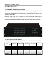
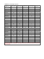
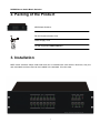
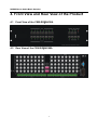
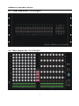
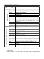
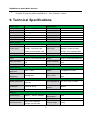
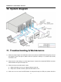
PTN
m
Electronics
CSW-RGBHV88A Matrix Switchers System
User Manual
Notice:
This RGBHV Matrix Switchers User Manual takes example of the Matrix model
MRG88A. It can be use d as user ’s manual of other RGBHV matrix switcher
models.
This manual is only an instruction for operators, not for any maintenance u sage.
The functions described in this version are updated till Jan 2010. Any changes of
functions and parameters sin ce then will be informed separat ely. Please refer to
the dealers for the latest details.
This manual is copyright PTN Electro nics Limited. All rights reserved. No p art of
this publication may be copied or reproduced without the prior written consent of
PTN Electronics Limited.
All product function is valid till 2010-1-1
RGBHV/Stereo Audio Matrix Switcher
! Safety Operation Guide
SAFETY PRECAUTIONS
Please read all instructions before attempting to unpack, install or operate this
equipment and before connecting the power supply.
Please keep the following in mind as you unpack and install this equipment:
• Always follow basic safety precaution to reduce the risk of fire, electrical shock
and injury to persons.
• To prevent fire or shock hazard, do not expose the unit to rain, moisture or install
this product near water.
• Never spill liquid of any kind on or into this product.
• Never push an object of any kind into this product through any openings or
empty slots in the unit, as you may damage parts inside the unit.
• Do not attach the power supply cabling to building surfaces.
• Use only the supplied power supply unit (PSU). Do not use the PSU if it is damaged.
• Do not allow anything to rest on the power cabling or allow any weight to be
placed upon it or any person walk on it.
• To protect the unit from overheating, do not block any vents or openings in
the unit housing that provide ventilation and allow for sufficient space for air
circulate around the unit.
ii
RGBHV/Stereo Audio Matrix Switcher
Contents
1. INTRODUCTION ................................................................................................................................ 1
1.1
1.2
About MRG Matrix Switcher System ...................................................................................... 1
MRG Matrix Switcher Models .................................................................................................. 1
2. PACKING OF THE PRODUCT ........................................................................................................... 3
3. INSTALLATION .................................................................................................................................. 3
4. FRONT VIEW AND REAR VIEW OF THE PRODUCT ....................................................................... 4
4.1
4.2
4.3
4.4
Front View of the 5*%+9$ ................................................................. 4
Rear View of the 5*%+9$ .................................................................. 4
Front View of the5*%+9$ ................................................................................ 5
Rear View of the 5*%+9$ ................................................................................. 5
4.5
4.6
Front View of the 5*%+9$.................................................................................................. 6
Rear View of the 5*%+9$ ................................................................................................... 6
5. EXTERNAL CONNECTION ............................................................................................................... 7
5.1 Introduction of the Input and Output Connectors ................................................................. 7
5.2 Connection of RS-232 Communication Port .......................................................................... 7
5.2.1 Connection with Control Systems ........................................................................................ 8
5.2.2 Connection with Computer .................................................................................................. 8
5.3
How to Connect with the Input and Output Terminals ................................................................ 8
6. OPERATION OF THE CONTROL PANEL.......................................................................................... 9
6.1
6.2
6.3
Front Panel Description ........................................................................................................... 9
Command Format of the Switching Operation .................................................................... 10
Examples of Operation ............................................................................................................ 10
7. USAGE OF THE REMOTE CONTROLLER ..................................................................................... 10
8. COMMUNICATION PROTOCOL AND COMMAND CODES ............................................................ 11
9. TECHNICAL SPECIFICATIONS....................................................................................................... 14
10. SYSTEM DIAGRAM ....................................................................................................................... 14
11. TROUBLESHOOTING & MAINTENANCE ..................................................................................... 15
iii
RGBHV/Stereo Audio Matrix Switcher
1. Introduction
1.1 About MRG Matrix Switcher System
MRG series Matrix switcher is a high-performance professional computer and audio signal switcher that
can be used for cross switching of multi computer and audio signal. Independent RGBHV component
and balanced/unbalanced I/O terminals make each component signal transmit and switch separately;
this design can reduce attenuation of signal transmission to minimum and output the image and audio
signal in high-fidelity quality.
MRG series switcher mostly apply in broadcasting TV engineering, multi-media meeting room, big
screen display engineering, television education, command control center etc. It provides power-fail
locale protection function, LED indicating, A/V timing & separating switching function. With RS232
interface, it can be worked with PC, remote control system and any other far-end control system
devices. The user manual takes MRG88A as example, other models can take reference from it too.
F 1-1
1.2 MRG Matrix Switcher Models
According to different situation and users, the MRG series can be classified into the following models:
Video Inputs
Video Outputs
Audio Inputs
Audio Outputs
RS232
Interface
MRG82
8
2
×
×
√
MRG82A
8
2
8
2
√
MRG84
8
4
×
×
√
MRG84A
8
4
8
4
√
MRG88
8
8
×
×
√
MRG88A
8
8
8
8
√
MRG164
16
4
×
×
√
MRG164A
16
4
16
4
√
Specifications
Models
1
RGBHV/Stereo Audio Matrix Switcher
Video Inputs
Video Outputs
Audio Inputs
Audio Outputs
RS232
Interface
MRG168
16
8
×
×
√
MRG168A
16
8
16
8
√
MRG1616
16
16
×
×
√
MRG1616A
16
16
16
16
√
MRG248
24
8
×
×
√
MRG248A
24
8
24
8
√
MRG2416
24
16
×
×
√
MRG2416A
24
16
24
16
√
MRG2424
24
24
×
×
√
MRG2424A
24
24
24
24
√
MRG328
32
8
×
×
√
MRG328A
32
8
32
8
√
MRG3216
32
16
×
×
√
MRG3216A
32
16
32
16
√
MRG3224
32
24
×
×
√
MRG3224A
32
32
32
24
√
MRG3232
32
32
×
×
√
MRG3232A
32
32
32
32
√
Specifications
Models
All modules above are for combined case design.
MRG4824
48
24
×
×
√
MRG4832
48
32
×
×
√
MRG4848
48
48
×
×
√
MRG6424
64
24
×
×
√
MRG6432
64
32
×
×
√
MRG6448
64
48
×
×
√
MRG6464
64
64
×
×
√
MRG9664
96
64
×
×
√
MRG9696
96
96
×
×
√
MRG12864
128
64
×
×
√
MRG12896
128
96
×
×
√
MRG128128
128
128
×
×
√
All modules above are for separated case design, audio case is the optional accessory. There will be
wider bandwidth.
RGBHV/Stereo Audio Matrix Switcher
2. Packing of the Product
MRG Matrix Switcher
RS-232 Communication Cord
Power Supply Cord
CD with Application SWITCHER 2.0
3. Installation
MRG matrix switchers adopt metal shell and can be stacked with other device. Moreover, they are
rack-mountable enclosure and can be installed in the standard 19 inches case.
3
RGBHV/Stereo Audio Matrix Switcher
4. Front View and Rear View of the Product
4.1
Front View of the CSW-RGBHV88A
、
4.2
Rear View of the CSW-RGBHV88A
、
4
RGBHV/Stereo Audio Matrix Switcher
4.3
Front View of the CSW-RGBHV88A
4.4
Rear View of the CSW-RGBHV88A
5
RGBHV/Stereo Audio Matrix Switcher
4.5 Front View of the CSW-RGBHV88A
4.6 Rear View of the CSW-RGBHV88A
6
RGBHV/Stereo Audio Matrix Switcher
Some more models:
MRV 24 channels series
MRV 32 channels series
MRV 48 channels series
MRV 64 channels series
MRV 96 channels series
MRV128 channels series
5. External Connection
5.1 Introduction of the Input and Output Connectors
According to different type of matrix, computer signal I/O interface are make up of Channel 8,
Channel 16,Channel 24,Channel 32,Channel 48,Channel 64,Channel 96, Channel 128 BNC
female terminals, audio signal I/O terminals are make up of Channel 2,Channel 4,Channel 8,
Channel 16,Channel 24,Channel 32,Channel 48,Channel 64,Channel 96,Channel 128 3.8mm
captive screw connectors. The channel number of MRG16X16 computer signal I/O terminals are
form Channel 1 to Channel 16(form left to right, display in two rows), The interfaces are R,G,B,
H,V signal terminals of the computer(form up to down),the channel number of audio signal I/O
terminals are form Channel 1 to Channel 16(from left to right).Please refer to shell silk-screen
figure about other types of interface.
5.2 Connection of RS-232 Communication Port
Except the front control panel, the MRG matrix switcher can be control by far-end control system
(Such as PC,CRESTRON control system, AMX control system) or through the Ethernet control
via the RS-232 communication port.
This RS-232 communication port is a female 9-pin D connector. The definition of its pins is as the
table below.
Pin No.
Name
Function
1
N/u
Unused
2
Tx
Transmit
3
Rx
Receive
4
N/u
Unused
5
Gnd
Ground
6
N/u
Unused
7
N/u
Unused
8
N/u
Unused
9
N/u
Unused
7
RGBHV/Stereo Audio Matrix Switcher
5.2.1 Connection with Control Systems
With the RS-232 port, the MRG matrix switchers can be control by several kinds of control
systems.
5.2.2 Connection with Computer
When the switcher connects to the COM1 or COM2 of the computer with control software, users
can control it by that computer.
To control the switcher, users may use the RS232 software
F 5-1
Connection between MRG matrix switcher and the computer
5.3 How to Connect with the Input and Output Terminals
The MRG matrix switchers may take DVD players, computers, graphic workstations and digital showing
platform as their input signal source, and projectors, video recorders, displayers and amplifiers as their
output signal destinations according to different situation.
RGBHV connection:
The MRG matrix switchers support the Composite Video, Component Video (YPbPr), Super Video (YC)
and VGA signal source. RGBHV signal output terminals or YC output terminals are needed in AV device;
RGBHV signal output terminals are needed in VGA device.
The BNC connector is shown as the figure below.
Tip (+)
Sleeve ( )
BNC Connector
If the VGA device doesn’t with RGBHV output terminals, please convert the signals with a VGA to
RGBHV switcher for getting high quality MRG output effects.
Please use the special five core RGBHV signal cord to connect the input and output devices and
connect the BNC connector R(red)、G(green)、B(blue)、H(horizontal)、V(vertical)carefully.
Attention:
Please make sure the RGBHV connectors from the source and to the destination should be in the same
order, otherwise it world cause color loss or no output signal at all.
Audio signal connection:
“AUDIO INPUT”, “AUDIO OUTPUTS” audio network interface in RGBHV matrix switchers can be
connected to the audio signal and amplify of the DVD player.
8
RGBHV/Stereo Audio Matrix Switcher
Audio connection is complicated than video. It has two kinds of connection: balanced and unbalanced.
The balanced connection transmits a pair of balanced signals with two signal cords. Because
interferences will have the same intensity and the opposite phases on the two signal cords, it will be
counteracted in the end. For the low frequency extent of the audio signal, it would be easily interfered
under long distance transmission. Therefore,as an anti-interference connection , it is mostly used in
audio connection of special device.
The unbalanced connection transmits signals only with a signal cord. Without counteraction, it can be
interfered more easily. Accordingly, it is adopted for household appliance or some cases with low
technical demand.
Take the audio signal line for example: 1.Unbalanced: pin “G” connect to SLEEVE, pin “+” connect to
TIP, pin “–” connect to pin “G”; 2.Balanced: pin “G” connect to SLEEVE, pin “–” connect to RING, pin “+”
connect to TIP. As shown in the F 6-3:
F 5-3 Balanced/unbalanced connection on captive screw connector
To select which connection is up to the interface of the device. When available, the balanced
connection is the first choice. Before connection, please read the command or relevant demand in the
user manual carefully. In some cases, maybe there is balanced in source signal end but unbalanced in
the destination end. If in a nonstandard case, it is done to connect balanced for the balanced end and
unbalanced for unbalanced end. But if in a standard one, the converter must be used to switch the
signals as the same, balanced or unbalanced.
6. Operation of the Control Panel
6.1 Front Panel Description
“AV”
“VIDEO”
“AUDIO”
“1,2,3,4”
AV synchronal button: To transfer video and audio signal synchronously by the switcher
Example: To transfer both the video and the audio signals from input channel No.3 to
output channel No.4.
Operation: Press buttons in this order “AV”,“3”,, “4””.
Video button: To transfer only video signals from input channel to output channel
Example: To transfer video signals from input channel No.3 to output channel No.4.
Operation: Press buttons in this order “VIDEO”, “3”, “4”.
Audio button: To transfer only audio signals from input channel to output channel
Example: To transfer audio signals from input channel No.2 to output channel No.3.
Operation: Press buttons in this order ““AUDIO”, “2”, “3””.
I/O Keypads: Keys to select I/O channels.
Example: To transfer input channel No.3 to output channel No.1
Operation: Press buttons in this order : “3” in INPUT area, “1” in OUTPUT area.
9
RGBHV/Stereo Audio Matrix Switcher
6.2 Command Format of the Switching Operation
With the front control panel, the switcher could be control directly and rapidly by pressing the buttons
under below format.
“Menu” +“Input Channel” +“Output Channel 1”
“Menu”: “AV”, “Audio”, “Video”
“Input Channel”: Fill with the number of input channel to be controlled
“Output Channel”: Fill with the number of output channels to be controlled
6.3 Examples of Operation
Example 1:To transfer video and audio signals from input channel No.1 to output channel
No.3,4
AV
1
Video
2
Audio
3
4
1, Press the button for switching mode “AV” for the switching mode of video
and audio (“Audio” for the switching mode of audio only; “Video” for the
switching mode of video only)
2, Press the button for input channel number“1”
2
3
4
3,Press the button for the first output channel number “3”
2
3
4
4, Press the button for the second output channel number “4”
Then, switching OK !
audio/video switching from “1” to “3” and “4”
7. Usage of the Remote Controller
With the infrared remote controller, the matrix switcher could be control remotely. Because the function
buttons on the remote controller are the same with the ones on the front control panel, the remote
controller shares the same control operation and command format with the control panel.
10
RGBHV/S
Stereo Audiio Matrix Sw
witcher
The inputs
s
channels, from
0~9, and
plusing “10+”
for more
Menu, for
switching
source and
function
s
The outputs
channels, from
f
0~9, and
0+”
plusing “10
for more
8. Comm
C munica
ation Proto
ocol and Comm
mand
d
Code
es
With this command
c
syystem, the RS232
R
softw
ware is able to control & operate the
e MRG Matriix remotely.
Commun
nication pro
otocol:
11
RGBHV/Stereo Audio Matrix Switcher
Baud rate: 9600
Command
Types
Data bit: 8
Stop bit: 1
Command
Codes
Parity bit: none
Functions
System Command
Operation Command (PTN2.0 Command System)
/*Type;
Inquire the models information.
/%Lock;
Lock the keyboard of the control panel on the Matrix.
/%Unlock;
Unlock the keyboard of the control panel on the Matrix.
/^Version;
Inquire the version of firmware
/:MessageOff;
Turn off the feedback command from the com port. It will only show
the “switcher OK”.
/:MessageOn;
Turn on the feedback command from the com port.
Undo.
To cancel the previous operation.
Demo.
Switch to the “demo” mode, 1->1, 2->2, 3->3 … and so on.
[x1]All.
Transfer signals from the input channel [x1] to all output channels
All#.
Transfer all input signals to the corresponding output channels
respectively.
All$.
Switch off all the output channels.
[x1]#.
Transfer signals from the input channel [x1] to the output channel
[x1].
[x1]$.
Switch off the output channel [x1].
[x1] V[x2].
Transfer the video signals from the input channel [x1] to the output
channel [x2].
[x1]
V[x2],[x3],[x4].
Transfer the video signals from the input channel [x1] to the output
channels [x2], [x3] and [x4].
[x1] A[x2].
Transfer the audio signals from the input channel [x1] to the output
channel [x2].
[x1]
A[x2],[x3],[x4].
Transfer the audio signals from the input channel [x1] to the output
channels [x2], [x3] and [x4].
[x1] B[x2].
Transfer both the video and the audio signals from the input channel
[x1] to the output channel [x2].
[x1]
B[x2],[x3],[x4].
Transfer both the video and the audio signals from the input channel
[x1] to the output channels [x2], [x3] and [x4].
Status[x1].
Inquire the input channel to the output channel [x1].
Status.
Inquire the input channel to the output channels one by one.
Save[Y].
Save the present operation to the preset command [Y]. [Y] ranges
from 0 to 9.
Recall[Y].
Recall the preset command [Y].
Clear[Y].
Clear the preset command [Y].
Note:
1. [x1], [x2], [x3] and [x4] are the symbols of input or output channels ranged according to the
model of the matrix switcher. If the symbols exceed the effective range, it would be taken as a
wrong command.
2. In above commands, “[”and “]” are symbols for easy reading and do not need to be typed in
12
RGBHV/Stereo Audio Matrix Switcher
actual operation.
3. Please remember to end the commands with the ending symbols “.” and “;”.
Detail Examples:
1、 Transfer signals from an input channel to all output channels: [x1]All.
Example: To transfer signals from the input channel No.3 to all output channels.
“3All.”
Run Command:
2、 Transfer all input signals to the corresponding output channels respectively: All#.
Example: If this command is carried out on an MVG1616-A matrix switcher, the status of it will be:
1->1, 2->2, 3->3, 4->4……16->16.
3、 Switch off all the output channels: All$.
Example: After running this command, there will be no signals on all the output channels.
4、 Check the version of the firmware: /^Version;
To check the version of the firmware.
5、 Switch off the detail feedback command from the COM port: /:MessageOff;
Switch off the detail feedback information from the COM port. But, it will leave the “switch OK” as
the feedback, when you switch the matrix.
6、 Switch on the detail feedback command from the COM port: /:MessageOn;
Switch on the detail feedback information from the COM port. it will show the detail switch
information when it switch. Example: when switch 1->2 for Audio, it will feedback “A0102”.
7、 Transfer signals from an input channel to the corresponding output channel: [x]#.
Example: To transfer signals from the input channel No.5 to the output channel No.5. Run
Command: “5#.”
8、Switch off an output channel: [x]$.
Example: To switch off the output channel No.5. Run Command: “5$.”
9、Switch video signals command: [x1] V[x2].
Example: To transfer the video signals from the input channel No.3 to the output channel No.5.
Run Command: “3V5.”
10、Switch audio signals command: [x1] A[x2].
Example: To Transfer the audio signals from the input channel No.10 to the output channel
Run Command: “10A2.”
11、Switch both video and audio signals synchronously: [x1] B[x2].
Example: To transfer both the video and the audio signals from the input channel No.120 to the
output channel No.12,13,15. Run Command: “120B12,13,15.”
12、Inquire the input channel to the output channel [x]: Status[x].
Example: To inquire the input channel to the output channel No.23. Run Command: “Status23.”
13、Inquire the input channel to the output channels one by one: Status.
Example: To inquire the input channel to the output channels one by one. Run Command:
“Status.”
14、Save the present operation to the preset command [Y]: Save[Y].
Example: To save the present operation to the preset command No.7. Run Command: “Save7.”
15、Recall the preset command [Y]: Recall[Y].
Example: To recall the preset command No.5. Run Command: “Recall5.”
13
RGBHV/Stereo Audio Matrix Switcher
16、Clear the preset command [Y]: Clear[Y].
Example: To clear the preset command No.5.
Run Command: “Clear5.”
9. Technical Specifications
Video Input
Video Output
Input
8 RGBHV
Output
8RGBHV
Input Connector
Female BNC
Output Connector
Female BNC
Return Loss
<-30dB@5MHz
Return Loss
-30dB@5MHz
Input Level
0.5 ~ 2.0Vp-p
Output Level
0.5 ~ 2.0Vp-p
Input Impedence
75Ω
Output Impedence
75Ω
DC Offset
1.5V
Switching Type
Vertical interval
0 dB
Bandwidth
450MHz (-3dB), fully load
Video General
Gain
RGBHV, RGBS, RGsB,
Video Signal
RGBHV, RGBS, RGsB,
RsGsBs, component video,
Video Type
S-video, and composite video.
Switching Speed
S-video, and composite video .
200ns (Max.)
Crosstalk
Audio Input
Input
Input Connector
Input Impedance
RsGsBs, component video,
<-80dB@5MHz
Audio Output
8 stereo, balanced/unbalanced
Captive screw connectors, 5
Output
Output Connector
pole
8 stereo, balanced/unbalanced
Captive screw connectors, 5
pole
>10KΩ
Output Impedance
50Ω
20Hz ~ 20KHz
CMRR
>90dB@20Hz~20KHz
>80dB@1KHz
THD + Noise
Audio General
Frequency
Response
Stereo Channel
Separation
0.03%@1KHz at nominal
level
Control Parts
Serial Control Port
RS-232, 9-pin female D
Pin Configurations
connector
Front Panel
2 = TX, 3 = RX, 5 = GND
IR Remote
Default IR remote
Options
TCP/IP control by PTNET(PTN's programmable interface)
Control
Buttons
General
Power Supply
100VAC ~ 240VAC, 50/60Hz
Temperature
-20 ~ +70℃
Case Dimension
Power
Consumption
W483 x H87 x D260mm
(2U high, full rack wide)
14
30W
Humidity
10% ~ 90%
Product Weight
4.5Kg
RGBHV/Stereo Audio Matrix Switcher
10. System Diagram
11. Troubleshooting & Maintenance
1)
When the output image in the destination device connected to the MRG Matrix has ghost, such as
the projector output with ghost, please check the projector’s setting or try another high quality
connection cord.
2)
When there is a color losing or no video signal output, it may be the unmatched RGBHV connector
order between the input and output end.
3)
When the remote controller doesn’t works:
A. Maybe the battery is run out of, please change a new one.
B. Maybe the controller is broken, please ask the dealer to fix it.
4)
When user can not control the MRG Matrix by computer through its COM port, please check the
15
RGBHV/Stereo Audio Matrix Switcher
COM port number in the software and make sure the COM port is in good condition.
5)
If there is not “beep” sound when switching the I/O signal, please make sure the beeper is switched
on. If so, the beeper inside the matrix may be broken. Please send it to the dealer for fixing.
6)
When switching , the beeper beeps but without any output image:
A. Check with oscilloscope or multimeter if there is any signal at the input end. If there is no
signal input, it may be the input connection cord broken or the connectors loosen.
B. Check with oscilloscope or multimeter if there is any signal at the output end. If there is no
signal output, it may be the output connection cord broken or the connectors loosen.
C. Please make sure the destination device is exactly on the controlled output channel
D. If it is still the same after the above checking, it may be something wrong in the switcher.
Please send it to the dealer for fixing.
7)
If the output image is interfered, please make sure the system is earthed well.
8)
If the static becomes stronger when connecting the BNC connectors, it may be due to the incorrect
earthing of the power supply, Please earth it again correctly, and otherwise it would bring damage
to the switcher or shorten its natural life.
9)
If the Matrix can not be controlled by the keys on the front panel, RS232 port or remote controller,
the host may has already been broken. Please send it to the dealer for fixing.
16