1
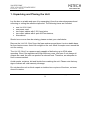
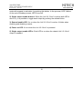
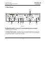
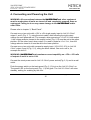
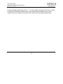
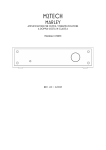
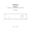
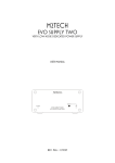
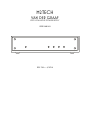
M2TECH
VAN DER GRAAF
VERY LOW NOISE POWER SUPPLY
USER MANUAL
REV. PrA – 6/2014
M2Tech
VAN DER GRAAF
VERY LOW NOISE POWER SUPPLY
www.m2tech.biz
REVISION PRA – JUNE 2014
Copyright © 2014, M2Tech Srl
2
M2Tech
VAN DER GRAAF
VERY LOW NOISE POWER SUPPLY
www.m2tech.biz
REVISION PRA – JUNE 2014
Warning!
Changes or modifications not authorized by the manufacturer can invalidate
the compliance to CE regulations and cause the unit to be no more suitable to
use. The manufacturer refuses every responsibility regarding damages to
people or things due to the use of a unit which has been subject to
unauthorized modifications or to misuse or to malfunction of a unit which has
been subject to unauthorized modifications.
This unit is compliant with the following CE regulations: CEI EN 55022:2009 Class B (Radiated
Emissions), CEI EN 55024:1999, CEI EN 55024:A2/2003, CEI EN 55024:IS1/2008 (Radio Frequency
Electromagnetic Fields, 50Hz Magnetic Field Immunity Test and Electrostatic Discharges – ESD).
For a proper operation of this unit, all connections to other equipment in the system must be
done when all equipment are off. Failing to comply with this advice may lead to damage to the
Van Der Graaf.
Copyright © 2014, M2Tech Srl
3
M2Tech
VAN DER GRAAF
VERY LOW NOISE POWER SUPPLY
www.m2tech.biz
REVISION PRA – JUNE 2014
The label above, printed on the product case, indicates that the product, when no more usable, can’t
be treated as generic garbage, but must be disposed of at a collection point for recycling of electrical
and electronic equipment, in compliance with the WEEE regulation (Waste of Electrical and Electronic
Equipment).
By making sure that this unit is correctly recycled, you will help preventing potential damages to
environment and human health, which could be caused by a wrong treatment of this product as
generic garbage. Materials’ recycling helps saving natural resources. For more in-depth information
about recycling this product, please contact M2Tech Srl.
WARNING: the information contained in this manual are considered to be reliable and accurate.
M2Tech reserves the right to change or modify the information any time, without prior advice.
It’s up to the customer to ensure that the manual being consulted is the latest version.
Copyright © 2014, M2Tech Srl
4
M2Tech
VAN DER GRAAF
VERY LOW NOISE POWER SUPPLY
www.m2tech.biz
REVISION PRA – JUNE 2014
Dear customer,
Thank you for purchasing VAN DER GRAAF. You are the owner of a very high quality
power supply with many unique features, designed to obtain the best performance in
conjunction with every M2Tech product.
VAN DER GRAAF implements a specific set of technological and functional solutions,
from the ultra-low noise, discrete components regulators, to the ability of selecting the
voltage at some outputs, to the sequence activation of used outputs.
VAN DER GRAAF is provided with a comprehensive set of outputs which allow for
powering any M2TECH product, from Evo series units to the Marley.
We’re sure that your expectations will be fulfilled by purchasing VAN DER GRAAF: your
M2Tech products will exhibit an incredible increase of their sonic performance, so you
can now prepare for a whole new listening experience!
Nadia Marino, CEO
Please note here your VAN DER GRAAF serial number and purchase info for future
reference:
S/N: _______________________ Date of Purchase: _________________________
Place of Purchase__________________________
Note: Proof of retail purchase, such as your purchase receipt, will be required in the unlikely
event that any warranty service will be required
Copyright © 2014, M2Tech Srl
5
M2Tech
VAN DER GRAAF
VERY LOW NOISE POWER SUPPLY
www.m2tech.biz
REVISION PRA – JUNE 2014
Copyright © 2014, M2Tech Srl
6
M2Tech
VAN DER GRAAF
VERY LOW NOISE POWER SUPPLY
www.m2tech.biz
REVISION PRA – JUNE 2014
TABLE OF CONTENTS
1. Unpacking and Placing the Unit.............................................................................. 9
2. Front Panel ........................................................................................................... 11
3. Back Panel............................................................................................................ 13
4. Connecting and Powering the Unit ....................................................................... 15
5. Cleaning the Unit .................................................................................................. 17
6. Outputs Toggle ..................................................................................................... 18
6.1. Setting and changing the activation sequence ............................................... 19
7. Overload and Protection ....................................................................................... 21
8. Specifications........................................................................................................ 22
Copyright © 2014, M2Tech Srl
7
M2Tech
VAN DER GRAAF
VERY LOW NOISE POWER SUPPLY
www.m2tech.biz
REVISION PRA – JUNE 2014
Copyright © 2014, M2Tech Srl
8
M2Tech
VAN DER GRAAF
VERY LOW NOISE POWER SUPPLY
www.m2tech.biz
REVISION PRA – JUNE 2014
1. Unpacking and Placing the Unit
Lay the box on a table and open it by separating it from the external paperwork and
removing or cutting the adhesive tape seal. The following items are included:
•
•
•
•
•
one VAN DER GRAAF;
one power cord;
two output cables with 5.5/2.1mm jacks;
two output cables with 4-pole XLR connectors;
this manual.
Should one or more item be missing, please contact your retail dealer.
Remove the VAN DER GRAAF from the foam enclosure and place it onto a stable base,
far from heat sources. Avoid full sunlight on the unit. Allow for ample room around the
unit for venting.
The VAN DER GRAAF is a power supply capable of delivering up to 60VA when
operating. Even if its regulators are high efficiency ones, and even if not always all
outputs are used, the unit can produce a relevant heat. Therefore, an adequate air
flow is recommended.
Avoid smoke, moisture, dirt and liquids from reaching the unit. Please note that any
signs of abuse will void warranty coverage.
Do not place the unit on thick carpets or inside a box or piece of furniture, not even
close to curtains.
Copyright © 2014, M2Tech Srl
9
M2Tech
VAN DER GRAAF
VERY LOW NOISE POWER SUPPLY
www.m2tech.biz
REVISION PRA – JUNE 2014
Copyright © 2014, M2Tech Srl
10
M2Tech
VAN DER GRAAF
VERY LOW NOISE POWER SUPPLY
www.m2tech.biz
REVISION PRA – JUNE 2014
2. Front Panel
3
4
5
1
2
Figure 1
1) Global enable button. Push this button to activate the VAN DER GRAAF when it’s in
standby (LED 4 on and LED 3 off). Following the operation of this button, all outputs
previously enabled by the user with their buttons (item 2, Fig. 1) will activate, in the
same sequence as the user manually activated them, with 1 second intervals. The
related LED’s will turn on to indicate activation. During the process, LED 3 blinks. At
the end of activation process, LED 3 glows steadily. When the VAN DER GRAAF is
active, user may put the VAN DER GRAAF in standby, disabling the outputs in reverse
Copyright © 2014, M2Tech Srl
11
M2Tech
VAN DER GRAAF
VERY LOW NOISE POWER SUPPLY
www.m2tech.biz
REVISION PRA – JUNE 2014
order with regards to activation, by pushing this button. In the process, LED 3 blinks.
At the end of disable process, LED 3 turns off.
2) Single output enable buttons. When the VAN DER GRAAF is active (both LED 4
and 3 on), it is possible to toggle each output by pushing the related button.
3) General enable LED. It’s on when the VAN DER GRAAF is active. It blinks when
enabling and disabling outputs.
4) Power on LED. It’s on when the VAN DER GRAAF is powered.
5) Single output enable LED’s. Each LED is on when the related VAN DER GRAAF
output is enabled.
Copyright © 2014, M2Tech Srl
12
M2Tech
VAN DER GRAAF
VERY LOW NOISE POWER SUPPLY
www.m2tech.biz
REVISION PRA – JUNE 2014
3. Back Panel
11
WARNING!
ELE CTRIC SHOCK HAZARD! DO NOT OPEN!
S/N:
NO USER SERVICEA BLE PARTS INSIDE
REFER ALL SERVICING TO QUA LIFIED PERSONNEL
M2TECH
!
RATING: 100-240VAC - 50/60 HZ
POWER CONSUMPTION: 60VA
FUSE: 2 x 2.5A Slow BLOW
VAN DER GRAAF
LOW NOISE POWER SUPPLY
15V
OUT 3
OUT 4
6
OUT 2
9V
OUT 1
7 8 7
MADE IN ITALY
9
10
Figure 2
6) Composite outputs. Connect M2Tech units provided with input for composite
supply +5V/+15V/-15V (e.g. the Marley) to this outputs using the stock cables.
Female 4-pole XLR sockets.
7) Single voltage outputs. Connect M2Tech units provided with input for single 15V
or 9V supply and maximum current sink 500mA (e.g. the Young DSD) to this outputs,
using the stock cables. Female 5,5/2,1mm jack.
Copyright © 2014, M2Tech Srl
13
M2Tech
VAN DER GRAAF
VERY LOW NOISE POWER SUPPLY
www.m2tech.biz
REVISION PRA – JUNE 2014
8) Output voltage selectors. Allow for choosing the voltage provided by outputs 1
and 2. Select voltage before connecting the units.
9) Power cord socket. Connect the stock power cord to this socket.
10) Power switch. Push this switch to toggle VAN DER GRAAF power. When powering
the unit, LED 4 (Fig. 1, Pag. 11) will glow and the VAN DER GRAAF will enter standby.
11) Fuse holder. It holds 2 slow blow 2.5A fuses.
Copyright © 2014, M2Tech Srl
14
M2Tech
VAN DER GRAAF
VERY LOW NOISE POWER SUPPLY
www.m2tech.biz
REVISION PRA – JUNE 2014
4. Connecting and Powering the Unit
WARNING: All connections between the VAN DER GRAAF and other equipment
must be made when all units are turned off and completely powered down or
unplugged. Failing to do so may cause damage to the VAN DER GRAAF and/or
other units.
Please refer to chapter 3, “Back Panel”.
Connect one or two units with +15V or +9V single supply input to VAN DER GRAAF
output 1 and 2 (Fig. 2, 7), using the stock cable, after selecting the right output
voltage for each powered unit. For example, when powering a Young DSD with output
1, the voltage selector closest to the output socket (Fig. 2, 8) must be set to the upper
position. On the other hand, when output 2 is used to power a hiFace Evo, then the
voltage selector closet to it must be set to the lower position.
Connect one or two units with composite supply input (+5V/+15V/-15V) to VAN DER
GRAAF output 3 and 4 (Fig. 2, 6), using the stock cables. One such unit is, for
example the Marley.
WARNING: VAN DER GRAAF total maximum current capability on +15V e -15V rails
of outputs 3 and 4 is set to 1.5A.
Connect the stock power cord to VAN DER GRAAF power socket(Fig. 2, 9) and to a wall
outlet.
Push the power switch on the back panel (Fig. 2, 10) to turn the VAN DER GRAAF on.
The power LED on the front panel (Fig. 1, 4) will glow. The VAN DER GRAAF will enter
standby, waiting for enabling by the user.
Copyright © 2014, M2Tech Srl
15
M2Tech
VAN DER GRAAF
VERY LOW NOISE POWER SUPPLY
www.m2tech.biz
REVISION PRA – JUNE 2014
Push the global enable button (Fig. 1, 1). At first enable, this action will have no effect
on outputs. At following enables, if the user has previously enabled one or more
outputs, they will activate in the same order as the user manually enabled them..
Copyright © 2014, M2Tech Srl
16
M2Tech
VAN DER GRAAF
VERY LOW NOISE POWER SUPPLY
www.m2tech.biz
REVISION PRA – JUNE 2014
5. Cleaning the Unit
The VAN DER GRAAF should be cleaned with a soft, slightly damp cloth. Do not use
alcohol or any other types of cleaning fluids as they could damage the unit.
Avoid fluids from dropping or leaking inside the unit. Fluids of any type poured into
the unit will void your warranty.
Be careful not to scratch the Plexiglas front screen.
Copyright © 2014, M2Tech Srl
17
M2Tech
VAN DER GRAAF
VERY LOW NOISE POWER SUPPLY
www.m2tech.biz
REVISION PRA – JUNE 2014
6. Outputs Toggle
When the VAN DER GRAAF is in standby (only LED 4 on), it is possible to activate it
pushing the global enable button (Fig. 1, 1). Immediately after this button operation,
the global enable LED (Fig. 1, 3) starts blinking and the previously enabled outputs
are activated in the order chosen by the user, at one second intervals. At the end of
the activation process, the active outputs are indicated by the related LED, which is
on, and the global enable LED glows steadily.
When VAN DER GRAAF is active, it can be put in standby pushing the global enable
button once more. Following this action, the global enable LED starts blinking and the
active outputs are shut down in the reverse order with respect to the activation order.
For example: if the activation sequence is: OUT3-OUT1-OUT2, the outputs will be
shut down in the following order: OUT2-OUT1-OUT3. At the end of the process, the
enable indication LED’s of all outputs are off and the global enable LED stops
blinking and remains off.
NOTE: the outputs activation sequence is stored by the VAN DER GRAAF when it
enters standby. If the power switch (Fig. 2, 10) is used to shut down the VAN DER
GRAAF,
GRAAF then the sequence, even if changed from the previous standby, is not
stored and the VAN DER GRAAF will use the last stored sequence upon following
activation, not the latest one.
The ability to activate the outputs in a chosen order is very useful whenever the units
in the chain powered by the VAN DER GRAAF need to be turned on in a given order.
Copyright © 2014, M2Tech Srl
18
M2Tech
VAN DER GRAAF
VERY LOW NOISE POWER SUPPLY
www.m2tech.biz
REVISION PRA – JUNE 2014
6.1. Setting and changing the activation sequence
Please refer to the VAN DER GRAAF as it is right after delivery from the dealer, turn
it on and push the global enable button. The global enable LED turns on. No output is
active (all output enable LED ‘s are off).
Enable the first output pushing its enable button.
NOTE: the first output to be enable must not necessarily be the one labelled as
‘OUT 1’. More simply, it will be the first one that the user wishes or needs to
activate.
As well, enable other outputs (all the available outputs or a part of them) in the
desired order.
NOTE: the order of activation chosen by the user will be stored by the VAN DER
GRAAF when it goes in standby. Should the unit, after outputs order setup be
turned off toggling the power switch while it’s active, it will not store the
sequence.
If an output is disabled, it will be deleted from the enable sequence. Any output
activated while a sequence is already set, will be added to the sequence as the last
output to be enabled. Therefore, if the present sequence is: OUT2-OUT1-OUT3 and
output 1 is disabled to be enabled again shortly after, the new sequence becomes:
OUT2-OUT3-OUT1.
Copyright © 2014, M2Tech Srl
19
M2Tech
VAN DER GRAAF
VERY LOW NOISE POWER SUPPLY
www.m2tech.biz
REVISION PRA – JUNE 2014
Copyright © 2014, M2Tech Srl
20
M2Tech
VAN DER GRAAF
VERY LOW NOISE POWER SUPPLY
www.m2tech.biz
REVISION PRA – JUNE 2014
7. Overload and Protection
All Van Der Graaf outputs are protected against unwanted overloads by solid state,
automatically resettable fuses. Anyway, continuous short-circuits may damage the
unit and must always be avoided.
In case of overload or short-circuit at one output, the behaviour of the unit is such that
other outputs may be affected.
Whenever an overload condition is detected, it’s recommended that user turns the
VAN DER GRAAF off and detaches all powered units. Each unit must then be checked
with its stock wall adaptor to find out which unit is defective.
Then working units may be connected back to the VAN DER GRAAF.
Copyright © 2014, M2Tech Srl
21
M2Tech
VAN DER GRAAF
VERY LOW NOISE POWER SUPPLY
www.m2tech.biz
REVISION PRA – JUNE 2014
8. Specifications
Output voltage: ................................. 9VDC or 15VDC (outputs 1 and 2)
+5VDC/+15VDC/-15VDC (output 3 and 4)
Output current:.................................. 500mA (outputs 1 and 2)
500mA (+5V, output 3 and 4)
1A (+/-15V, output 3 and 4)*
Noise:................................................ 2.9uVrms (20Hz-20kHz, A weighted, rated load
Outputs: ............................................ 5.5/2.1mm jacks, positive on tip (outputs 1 and 2)
female 4-poles XLR (outputs 3 and 4)
Input voltage: .................................... 90-260VAC, 50/60Hz
Power consumption: ......................... 60VA
Fuse:................................................. slow blow 2.5A
Input:................................................. IEC socket with fuse holder and EMI filter
Output voltage selection: .................. by DIP-switches on back panel
Outputs activation: ............................ sequence set by user
Output reset: ..................................... inverse sequence with regards to activation
Size:.................................................. 200x50x200mm (w x h x d)
Weight............................................... 2.2kg (device only)
3.5kg (packed)
* maximum total current available on each of the two outputs rails is 1,5A
Copyright © 2014, M2Tech Srl
22