1
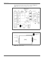
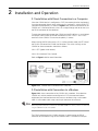
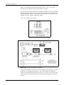
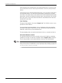
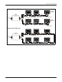
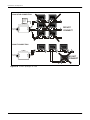
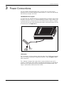
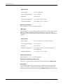
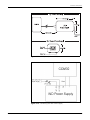
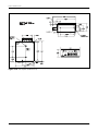
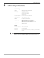
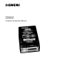
COM32
Installation & Operation Manual
DANGER
ElectricaI equipment contains hazardous voltages and high
speed moving parts.
Can cause death, serious injury or property damage.
See safety instruction contained herein. Restrict use to qualified
personnel.
The use of unauthorized parts in the repair of the equipment
or tampering by unqualified personnel will result in dangerous
conditions that can cause death, serious injury or property
damage.
IMPORTANT
The information contained herein is general in nature and not
intended for specific application purposes. It does not relieve
the user of responsibility to use sound practices in application, installation, operation, and maintenence of the
equipment purchased. Siemens reserves the right to make
changes at any time without notice or obligations. Should a
conflict arise between the general information contained in
this publication and the contents of drawings or supplementary material or both, the latter shall take precedence.
QUALIFIED PERSONNEL
For the purposes of this manual and product labels, "qualified
personnel" is one who is familiar with the installation,
construction, or operation of the equipment and the hazards
involved. In addition, s/he has the following qualifications:
(a) is trained and authorized to energize, de-energize,
clear, ground, and tag circuits and equipment in accordance
with established safety practices.
(b) is trained in the proper care and use of protective gear
equipment such as rubber gloves, hard hat, safety glasses or
face shields, flash clothing, etc., in accordance with established safety procedures
(c) is trained in rendering first aid.
SUMMARY
These instructions do not purport to cover all details or variations in equipment, nor to provide for every possible
contingency to be met in connection with installation, operation, or maintenence. Should further information be
desired or should particular problems arise which are not covered sufficiently for the purchaser’s purposes, the
matter should be referred to the local the sales office.
THE CONTENTS OF THIS INSTRUCTION MANUAL SHALL NOT BECOME PART OF OR MODIFY ANY PRIOR OR
EXISTING AGREEMENT, COMMITMENT OR RELATIONSHIP. THE SALES CONTRACT CONTAINS ALL OBLIGATIONS OF SIEMENS ENERGY & AUTOMATION, INC. THE WARRANTY CONTAINED IN THE CONTRACT
BETWEEN THE PARTIES IS THE SOLE WARRANTY OF SIEMENS ENERGY & AUTOMATION, INC.
ACCESS, ISGS, Isolated Multi-Drop, S7-I/O, SBwin, SAMMS-LV, SAAMS-MV,SEAbus,SIEServe, Static Trip III,
Wisdom, and WinPM are trademark, Sensitrip and Sentron are registered trademarks of Siemens Energy &
Automation, Inc. SIEMENS is a registered trademark and Windows is a trademark of Microsoft Corporation. All
other product names mentioned herein are used for identification purposes only and may be the trademarks or
registered trademarks of their respective companies.
Contents
1 COM32 Features . . . . . . . . . . . . . . . . . . . . . . . . . . . . . . . . . . . . . . . . . . . . . . 5
1.1 Introduction . . . . . . . . . . . . . . . . . . . . . . . . . . . . . . . . . . . . . . . . . . 5
2 Installation and Operation . . . . . . . . . . . . . . . . . . . . . . . . . . . . . . . . . . . . . . 7
2.1 Installation with Direct Connection to a Computer . . . . . . . . . . . . . 7
2.2 Installation with Connection to a Modem . . . . . . . . . . . . . . . . . . . . 7
2.3 RS-485 Connections . . . . . . . . . . . . . . . . . . . . . . . . . . . . . . . . . . . . 9
General Bus Wiring Considerations . . . . . . . . . . . . . . . . . . . . . . 9
Recommended Topologies . . . . . . . . . . . . . . . . . . . . . . . . . . . . 9
Straight-Line Topology . . . . . . . . . . . . . . . . . . . . . . . . . . . . . . . . 9
Loop Topology . . . . . . . . . . . . . . . . . . . . . . . . . . . . . . . . . . . . . 10
Connection Methods to Avoid . . . . . . . . . . . . . . . . . . . . . . . . . 10
3 Power Connections . . . . . . . . . . . . . . . . . . . . . . . . . . . . . . . . . . . . . . . . . . . 13
-NOPWR (No Power) Option . . . . . . . . . . . . . . . . . . . . . . . . . .
-UNI Option . . . . . . . . . . . . . . . . . . . . . . . . . . . . . . . . . . . . . . .
Standards Compliance . . . . . . . . . . . . . . . . . . . . . . . . . . . . . .
-IND Option . . . . . . . . . . . . . . . . . . . . . . . . . . . . . . . . . . . . . . .
Standards Compliance . . . . . . . . . . . . . . . . . . . . . . . . . . . . . . .
Mechanical and Mounting Dimensions . . . . . . . . . . . . . . . . . .
Connections . . . . . . . . . . . . . . . . . . . . . . . . . . . . . . . . . . . . . . .
13
13
14
14
14
14
14
4 Technical Specifications . . . . . . . . . . . . . . . . . . . . . . . . . . . . . . . . . . . . . . . 17
COM32 INSTALLATION & OPERATION MANUAL
iii
Siemens maintains control of all specifications for the SEAbus and SEAbus Plus protocols. A modification to a
protocol for any type of device must be approved by Siemens Energy & Automation, Inc. to guarantee compatibility.
Any changes made must be backward compatible so that existing products can coexist on the communications bus
without having to support the newer features of the protocol
Siemens continuously strives to ensure backward compatibility, reliability, and easy implementation of both protocols
to meet current market communications requirements. Siemens therefore reserves the right to make improvements
including changes to specifications at any time without notice or obligation.
ACCESS, ISGS, Isolated Multi-Drop, Power Monitor, Power Monitor PC, SAMMS, SAMMS-LV, SAMMS-MV, SCOR,
SEAbus, SEAbus Plus, SIEServe, Static Trip III,WinPM, and Wisdom are trademarks, Sensitrip and Sentron are registered trademarks of Siemens Energy & Automation, Inc.
Quattro Pro is a registered trademark of Borland International, Inc.
CROSSTALK is a registered trademark of Digital Communications Associates, Inc.
iv
COM32 INSTALLATION & OPERATION MANUAL
COM32 Features
1
COM32 Features
!
1200, 2400, 4800 or 9600 baud operation.
!
Full electrical isolation between RS-485 and RS-232 to 500V.
!
Works directly with Siemens SCADA software or with other proprietary software.
!
Compact, attractive package.
!
May be used with direct computer connection or with modems — switch
allows enabling of the receive by carrier detect option.
!
RS-485 transmit enable may be controlled automatically or by the RS-232 RTS
line.
!
Powered from AC adapter (included).
1.1 Introduction
When an RS-232 communications line is connected to an RS-485 communications
bus, there are several basic problems:
1.
RS-232 is fundamentally a duplex standard. Separate signals can be
transmitted and received simultaneously. RS-485 is strictly simplex. Signals
can only be transmitted in one direction at a time. When interfacing between
an RS-232 device and an RS-485 device, there must be some method of
controlling whether the RS-232 device listens or transmits onto the bus. The
COM32 provides two ways of doing this. The first is the standard approach of
using the RS-232 RTS signal to provide directional control for the COM32
module. This works fine provided that the RTS signal is available, and the
computer software being run on the PC supports this method of operation. In
many cases, these conditions are not met.
The COM32 is unique in that it also supports an “automatic” mode which
allows it to detect the change of RS-232 devices from a listen mode to
transmit mode. All the timing functions required to do this are handled
automatically for rates of 1200 to 9600 baud.
2.
RS-485 loops are generally quite long, and they often run through electrically
noisy environments. The risk of exposure to transient voltage surges and
spikes on an RS-485 line is substantially higher than on an RS-232 line. The
COM32 module uses isolation between the RS-232 and RS-485 sections to
protect the computer equipment from damage.
COM32 INSTALLATION & OPERATION MANUAL
5
COM32 Features
The operational block diagram for the COM32 is provided in Figure 1.1.1.
Figure 1.1.2 shows the physical features of the COM32.
Figure 1.1.1 COM32 Operational Block Diagram
Figure 1.1.2 COM32 Features
6
COM32 INSTALLATION & OPERATION MANUAL
Installation and Operation
2
Installation and Operation
2.1 Installation with Direct Connection to a Computer
Since the COM32 device is configured as DCE (data communications equipment)
it may be connected directly to the serial port of a standard PC, which will be DTE
(data terminal equipment). As shown in Figure 2.1.1, the DB-23 connector on the
COM32 unit is connected directly (wires run straight through and do not cross) to
the DB-23 connector of the computer.
To make the connection between the COM32 and the RS-485 bus, use a shielded
twisted-pair cable. Make the RS-485 connections to the “Data +” and “Data -”
terminals of the COM32. Ensure that the polarity is correct.
When running WinPM software on a PC, in a direct connect mode, the RTS line of
the RS-232 will control the RS-285 data direction. The switch settings on the
COM32 for direct connection should be as follows:
SW-1: OFF (ignore carrier detect)
SW-2: ON (Automatic Flow Control)
Refer to Figure 2.1.1 for more information.
Figure 2.1.1 COM32 Direct Connection to a Computer
2.2 Installation with Connection to a Modem
Figure 2.2.1 shows connection of the COM32 with a modem. Since both the
COM32 unit and the modem are configured as DCE (data communications
equipment) the interface between the two must be done using a null modem
cable. A null modem cable swaps certain pins between the two ends.
NOTE
When using a dial-up modem to communicate with 4000 or 9000-series meters, Siemens recommends
using the COM128 instead of the COM32.
The DB-25 connector on the COM32 converter is connected to the DB-25
connector of the modem using the null modem cable. A shielded twisted-pair
COM32 INSTALLATION & OPERATION MANUAL
7
Installation and Operation
cable is used to make the RS-485 connections to the “Data +” and “Data -”
terminals of the COM32. Ensure that the polarity is correct.
If the converter is being used to allow the modem to monitor an active RS-485 data
loop, the converter must be set to pass data to the modem only after the carrier
has been detected, otherwise the modem will not answer. For connection with a
modem the switch settings should be as follow:
SW-1: ON (wait for carrier detect)
Figure 2.2.1 COM32 Configuration
Figure 2.2.2 COM32 Connection to a Modem
Switch SW-2 controls whether the RTS signal controls the RS-485 bus, or if the
RS-485 bus is controlled automatically. If the software does not support RTS
control, or the modem being used does not pass this signal, SW-2 must be sent
to the automatic internal timing mode. The two possible settings of SW-2 are as
follows:
8
COM32 INSTALLATION & OPERATION MANUAL
Installation and Operation
SW-2: OFF (RTS controls the RS-485 bus)
SW-2: ON (RTS is not available: the converter uses internal timing to control the
RS-485 bus)
Refer to Figure 2.2.1 for more information.
2.3 RS-485 Connections
RS-485 communications allows multiple devices to be connected on the same
bus. Up to 32 devices can be connected on a single RS-485 bus, which consists
of a shielded twisted pair cable. The overall length of the RS-485 cable connecting
all devices cannot exceed 4000 ft. (1219 m).
A COM32 is required in order to connect an RS-485 communications bus to a
computer or other RS-232 equipped device.
General Bus Wiring Considerations
Devices connected on the bus, including the COM32 and other instrumentation,
must be wired as follows:
1.
Use a good quality shielded twisted pair cable for each RS-485 bus. It is
recommended that AWG 22 (0.6 mm) or larger conductor size be used.
2. Ensure that the polarity is correct when connecting to the RS-485 port (+) and
(-) terminals of each device.
3. The shield of each segment of the RS-485 cable must be connected to ground
at one end only.
C AUTION
Do not connect ground to the shield at both ends of a segment. Doing so allows ground loop currents
to flow in the shield, inducing noise in the communications cable.
4. Cables should be isolated as much as possible from sources of electrical noise.
Recommended Topologies
Devices on an RS-485 bus are connected in a point-to-point configuration, with the
(+) and (-) terminals of each devices connected to the associated terminals on the
next device. This is illustrated in Figure 2.3a.
While there are many topologies that can be used to connect devices on an RS485 communication bus, the two recommended methods are the straight-line and
loop topologies.
Straight-Line Topology
The straight-line wiring method is illustrated in Figure 2.3a.
COM32 INSTALLATION & OPERATION MANUAL
9
Installation and Operation
Each end point of the straight-line bus must be terminated with a 1/4 watt resistor.
These termination resistors reduce signal reflections which may corrupt data on
the bus.
Termination resistors are connected between the (+) and (-) terminals of the device
at each end of the bus. This device can include either a converter or any other
instrument. The value of the resistor should match the line impedance of the cable
being used. For AWG 22 shielded twisted pair cable, values between 150 and 300
ohms are typical. Consult the cable manufacturer’s documentation for the exact
impedance of your cable.
Loop Topology
The loop wiring method is illustrated in Figure 2.3a. The COM32 can exist at any
position on the RS-485 bus.
One advantage of the loop topology is that a single-open circuit fault condition
anywhere on the loop will not result in the loss of communication between the
computer station and any of the remote devices.
The loop topology does not require termination resistors at any point on the bus.
Connection Methods to Avoid
Any device connection that causes a branch in the main RS-485 bus should be
avoided This includes star and tee (T) methods. Refer to Figure 2.3b for examples.
These wiring methods cause signal reflections that may cause interference.
NOTE
At any connection point on the RS-485 bus, no more than two (2) cables should be connected. This
includes connection points on instruments, converters, and terminal strips. Following this guideline ensures that star and tee connections are avoided.
10
COM32 INSTALLATION & OPERATION MANUAL
Installation and Operation
RS-485 STRAIGHT-LINE TOPOLOGY
Last
RS-485 Device
(End Point)
RS-485 PORT
COM32
RS-485 PORT
RS-485 PORT
SHLD
SHLD
SHLD
RS-232C to RS-485 Converter
SHLD
RS-485 Cable
RT
AWG 22 shielded twisted pair. Overall length: 4000 ft. maximum.
RS-485
RS-232C
Computer
or Modem
Termination Resistor
See Section 3.2.3.
Last
RS-485 Device
(End Point)
RS-485 PORT
RS-485 PORT
RS-485 PORT
SHLD
SHLD
SHLD
RT
Termination Resistor
See Section 3.2.3.
RS-485 LOOP TOPOLOGY
RS-485 PORT
COM32
RS-485 PORT
RS-485 PORT
SHLD
SHLD
SHLD
SHLD
RS-232C to RS-485 Converter
RS-232C
RS-485
SHLD
Computer
or Modem
RS-485 Cable
AWG 22 shielded twisted pair. Overall length: 4000 ft. maximum.
RS-485 PORT
SHLD
RS-485 PORT
SHLD
RS-485 PORT
SHLD
Figure 2.3a RS-485 Straight-Line and Loop Topologies
COM32 INSTALLATION & OPERATION MANUAL
11
Installation and Operation
RS-485 STAR CONNECTION
3-way star
connection
point not
allowed
RS-485 PORT
RS-485 PORT
SHLD
SHLD
COM32
RS-232C to RS-485 Converter
RS-485 PORT
RS-485 PORT
SHLD
RS-485
RS-232C
Computer
or Modem
DO NOT
CONNECT
SHLD
RS-485 PORT
RS-485 PORT
SHLD
SHLD
RS-485 T-CONNECTION
RS-485 PORT
SHLD
COM32
RS-485 PORT
RS-485 PORT
SHLD
SHLD
SHLD
RS-232C to RS-485 Converter
RS-232C
Computer
or Modem
RS-485
SHLD
RS-485 PORT
DO NOT
CONNECT
SHLD
Figure 2.3b RS-485 Topologies to Avoid
12
COM32 INSTALLATION & OPERATION MANUAL
Power Connections
3
Power Connections
The wall adapter should be plugged into a standard 120 VAC outlet. When
powered, the TXD and RXD indicators should come on. As data is passed through
the converter, the lights will flicker.
-NOPWR (No Power) Option
A COM32 with the -NOPWR option must be powered by an external source rated
between 7VDC and 12VDC. It is recommended that a power supply adapter with
an output of 9VDEC at 500mA be used. The COM32 with this option is supplied
with a pair of leads with spade connector terminations which extend form the side
of the enclosure (see Figure 3.1.1).
Figure 3.1.1 -NOPWR Option
-UNI Option
The -UNI option is a universal power supply that allows the COM32 to be powered
from any standard international voltage and frequency. Refer to Figure 3.1.4 for
more information.
The “table-top” design of the supply allows it to be positioned a top any flat
surface. A standard IEC 3-pin socket is provided for connection of an appropriate
power cord (not supplied) to match the configuration of the power outlet. The
supply is permanently connected to the COM32.
COM32 INSTALLATION & OPERATION MANUAL
13
Power Connections
Specifications
Input Voltage:
90 VAC to 264 VAC
Input Frequency Range:
47 Hz to 440 Hz
Protection:
Internal Fuse
Operating Temperature:
0°C to 40°C (32°F to 104°F)
Storage Temperature:
-40°C to 85°C (-40°F to 185°F)
Standards Compliance
The UNI option is CSA, UL, and VDE approved.
-IND Option
The -IND option is a universal power supply that allows the COM32 to be powered
from any standard international voltage and frequency. The power supply is
designed for industrial applications where it can be mounted on the wall or door of
a cabinet.
Specifications
Input Voltage:
85 VAC to 264 VAC (110 VDC to 340 VDC)
Input Frequency Range:
47 Hz to 440 Hz
Protection:
Internal Fuse
Operating Temperature:
0°C to 50°C (32°F to 122°F) relative humidity,
non-condensing
Storage Temperature:
-20°C to 75°C (-4°F to 167°F)
Standards Compliance
The IND option is CSA, UL, and VDE approved.
Mechanical and Mounting Dimensions
Dimensions in inches except where otherwise indicated. Refer to Figure 3.1.4.
Connections
The IND power supply must be connected to a dedicated fused feed voltage
source. The COM32 is connected to the IND supply using the bare-end wires
extending from the COM32 enclosure. Refer to Figure 3.1.3 for more information.
14
COM32 INSTALLATION & OPERATION MANUAL
Power Connections
Figure 3.1.2 -UNI Option (Universal P/S)
Figure 3.1.3 Connecting the -IND Power Supply
COM32 INSTALLATION & OPERATION MANUAL
15
Power Connections
Figure 3.1.4 -IND Option (Industrial P/S)
16
COM32 INSTALLATION & OPERATION MANUAL
Technical Specifications
4
Technical Specifications
Electrical Ratings
Isolation:
500 V between RS-232 and RS-485 ports
Power Supply:
Standard 9VDC @ 500 mA
(120 VAC adapter supplied)
Alternate: 9 VDC @ 500 mA
(220 VAC adapter)
Operating Temperature:
0°C to 50°C (32°F to 122°F) ambient air
Storage Temperature:
-30°C to 70°C (-22°F to 158°F)
Humidity:
5 to 95 percent, non-condensing
Shipping Weight:
COM32: 0.24 kg; 8 oz.
COM32 with standard power supply: 0.47 kg; 1lb.
COM32 with alternate power supply: 0.63 kg; 1 lb. 6 oz.
Shipping Carton:
30 cm x 25 cm x 15 cm
(11.8” x 9.8” x 5.9”)
Features
Baud Rates Supported:
1200, 2400, 4800, 9600
RS-232 Ports:
One (Female DB-25)
RS-485 Ports:
One screw-down terminal blocks, each with (+), (-), and shield (SHLD)
terminals
NOTE
RS-485 port terminals all pass ANSI/IEEE C37.90A-1989 surge withstand and fast transient tests.
COM32 INSTALLATION & OPERATION MANUAL
17
Technical Specifications
Figure 4.1.1 COM32 Mechanical Dimensions
18
COM32 INSTALLATION & OPERATION MANUAL
Siemens Energy & Automation, Inc.
Power Management Technologies
3333 Old Milton Parkway
Alpharetta, GA 30005
For Nearest Sales Office
1.800.964.4114
© Siemens Energy & Automation, Inc.
Windows is a trademark and Microsoft is a registered
trademark of Microsoft Corporation.
All others are of Siemens AG.
Siemens is a registered trademark of Siemens AG.
Specifications are subject to change without notice.
www.sea.siemens.com
sales/salesoffices.html
For More Information Visit
www.sea.siemens.com/access
Order No. XXOM-104-0101
PDF 0101Printed in the U.S.A.