1
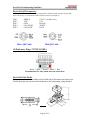
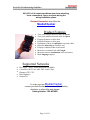
DeviceNet Troubleshooting Guidelines DeviceNet will not function correctly if design rules are not followed. Even a Network previously thought to be functioning correctly may begin to exhibit abnormal or anomalous operation due to incorrect system design. The following are tips to help locate and correct these abnormalities. For specific DeviceNet system installation information. Please refer the "DeviceNet Planning and Installation Manual". Manuals can be ordered via the Internet at http://www.theautomationbookstore.com/ Verify that all devices on the network have been certified by ODVA and carry the DeviceNet Conformance check on their name plate. Termination Resistors: A termination resistor equal to 121 Ohms 1% , 1/4W must be attached at each end of the Trunk cable. The resistors must be connected across the Blue & White wires of the DeviceNet cable. Resistor connection can be verified by disconnecting DeviceNet power and measuring the resistance across the Can_H & Can_L lines (Blue & White Wire). This can be measured with an Ohm meter. The reading should be approximately 60 Ohms. Very Important: The DeviceNet network will not operate correctly without terminating resistors. Termination resistors can be ordered from your local Allen-Bradley Distributor using the part number 1485A-C2. Page 1 of 15 DeviceNet Troubleshooting Guidelines Network Grounding: The DeviceNet cable must by grounded at only one location. This should be done closest to the center of the network. Connect the network Shield and Drain wire to an earth ground using #8 AWG wire up to a maximum 3m ( 10Ft ) in length.Also connect the Vconductor ( Black Wire) of the network trunk cable and the DC ground of the power supply to this ground connection. Power Supply Discussion: DeviceNet requires 24VDC. Use a power supply rated 24VDC (+/- 1% ). Make sure the power supply has it's own current limit protection. Provide fuse protection for each segment of the cable system. DeviceNet requires a power supply to have a rise time of less then 250mS to within 5% of its rated output voltage. The power supply must be sized correctly to provide each device with its required power. 1. The thin wire trunk line can only handle 3 amps and the thick wire trunk line can physically handle 8 amps. However, in North America the current is limited to 4 amps. Multiple power supplies can be installed on a DeviceNet network, but no section of cable should have more current flowing than the appropriate rating. An important note is that when putting multiple power supplies on a network; break the Red V+ wire between the power supplies. This effectively isolates the power supplies from each other. 2. Common mode voltage can sometimes be an issue on DeviceNet networks which have trunk lines that are extra long and/or have devices on them, drawing large currents at longer distances. If the voltage on the Black V- wire ever gets more than 4.65 volts different from one point of the network to another, then communication problems could occur. On an existing network, if the voltage between the Red V+ wire and the Black Vwire ever gets below 15 volts, then common mode voltage could be adversely affecting network communications. Adding an additional power supply or moving an existing power supply closer to the heavier current loads will normally cure common mode voltage problems. Important: It is recommended that the DeviceNet power supply should be used to power the DeviceNet network only. When multiple power supplies are required, verify that the V+ connection is broken between the supplies. Please refer to the " DeviceNet Planning and Installation Manual " for more specific installation procedures. Page 2 of 15 DeviceNet Troubleshooting Guidelines Verify Network Voltages It needs to be understood that DeviceNet is actually a three wire Differential Voltage network communication is accomplished by switching the CAN-H (White wire) and CAN-L (Blue wire) signals relative to the V- line ( Black Wire ). The CAN-H swings between 2.5 VDC (Recessive State) and 4.0 VDC (Dominant State) while the CAN-L swings between 1.5 VDC (Dominant State) and 2.5 VDC (Recessive State) Without a network master connected to the DeviceNet, the CAN-H and CAN-L lines should read between 2.5 VDC and 3.0 VDC relative to V- and the voltages should be identical. (Recessive State). Measure these voltages right at the SDN scanner. Use a voltmeter in DC mode. With a network master connected and polling the network, the CAN-H to V- voltage will be around +3.2 VDC. The CAN-L to V- voltage will be around 2.4 VDC. The reason these values appear a little different than the ranges shown on the scope trace, is that the signals are switching, which slightly affects the DC value being read by the VOM. If Can-H to V- and Can_L to V- are too low; less than 2.5 V dc and 2.0 V dc respectively the issue is probably a bad transceiver or bad wiring. To find a bad transceiver remove one node at a time measuring Can-H and Can-L to V- each time a device is removed. To check a transceiver (rough test) with everything removed from a device use an ohm meter to measure resistance between V+ and Can-H V+ and Can-L V- and Can-H V- and Can-L. These impedances should all be greater than 1 M ohm. Page 3 of 15 DeviceNet Troubleshooting Guidelines Examine the System Design of the Installation Walk the network if possible to determine the actual layout. ( Make a sketch of the network ) Check number of nodes Check cumulative drop length Check individual drop lengths Check branched drop length Check total trunk length, including long drop near the ends Check the termination location and measure the terminators Check the power supply cable length and gauge Check for one, and only one, earth ground of the V- and shield Break the combination shield/V- connection to frame ground and verify >1.0 Mohm to frame ground Check for one and only one V- to shield connection Break the shield/V- connection at the power supply and verify >1.0 Mohm shield to V- with 24VDC off Check for shorts of CAN- and/or CAN+ to shield or V- verify with an OHM meter Check the length and gauge of the earth ground connection Check total power load and its distribution points Check the Power Check trunk and drop current limits Check type (size and length) of cable bringing power into the trunk Measure the 24V supply at the middle and ends of the network Consider spot checking the power for noise with an oscilloscope It is recommended but not required that the 24 VDC Network Power for DeviceNet should be used for the DeviceNet network only to aid in eliminating noise issues. Check the Wiring Check lead dress in junction boxes Check that connectors are screwed together tightly Check that glands are screwed tightly Check for foreign material (electrical tape, RTV, etc.) in glands Check that nodes are not touching extremely hot or cold surfaces Check that cables are kept a few inches away from power wiring Check that cables are not draped on electric motors, relays, contactors or solenoids Check that cables are not constrained so as to place excessive tension on connectors Wiggle connectors to provoke intermittent failures Page 4 of 15 DeviceNet Troubleshooting Guidelines Check the Scanner Configuration Verify the scanlist Baud Rate Node Address Series/Revision of the 1747/1771-SDN scanner Refer to Knowbase for documents on factory defaulting DeviceNet Scanners Check the Nodes Cycle power to the 24V supply, this will reset the scanner to initialize the network Examine the scanner display codes to identify problem nodes. ( Reference the SDN manual for a description of these codes ) At problem nodes Blinking GREEN means the node is not being allocated by the scanner Check that the node is in the scan list Check that the scanner is not bus off Check if connection is timing out Blinking RED means no communication Check for missing power on all nodes Check if all other nodes are disconnected Check node baud rate ( Bad baud rate does not always cause buss off ) Check scanner, if a code 91 is displayed then the communications connection with the node has timed out. Recycle 24V supply and then reset scanner. Page 5 of 15 DeviceNet Troubleshooting Guidelines If scanner goes bus off again, The problem is some combination of • • • • • • • • Defective node Node baud rate Bad topology Bad connections Bad scanner Bad power Bad grounding Bad electrical noise A Solid RED light at power-up means two nodes have the same address. A Solid RED after allocation means bus off Check baud rate. If the problems persist: • • • Replace T-Tap Check topology Check power for noise with oscilloscope or power disturbance analyzer Finally if the problem remains after all else has been tried replace the node. ( Be sure to set the node address and baud rate on the replacement node, if applicable ) Page 6 of 15 DeviceNet Troubleshooting Guidelines Points to Remember • • • • • • • • • Pressing the reset button on the scanner does not reset the network Cycling the rack power does not reset the network When using a DeviceLink a bus off (solid RED) condition can only be cleared by cycling the 24V power Cycling power on the network will cause the scanner to go bus off DeviceNet 9000 bus off (solid RED) condition can be cleared by cycling the 24V power or by pressing the program button for several seconds Extreme care must be given to the task of setting initial addresses and baud rates because one incorrect node address or incorrect baud rate will cause other nodes to appear to be bad (solid RED). If the scanner is bus off (code 91), nodes will not re-allocate (flashing GREEN or RED) even if they are functioning correctly RSNetworx for DeviceNet and a 1770-KFD/1784-PCD can be used to identify the functioning nodes on the network. If a node goes bus off (solid RED for DeviceLink), and is replaced and still goes bus off, the problem is not the node but rather the setting of the address or baud rate or a network wide problem related to topology, grounding, electrical noise or an intermittent node MORE TROUBLESHOOTING TIPS • • • Try to distinguish, as soon as possible, a device problem from a media problem. Try to reduce the system to the smallest size, which still exhibits the problem. This can be done by removing nodes, drops, taps, or lengths of trunk can do this. Use substitution where possible to rule things out, but be careful! Actual Field Case: Product A works with Product B and not with Product C. We conclude that the problem is with Product C -- WRONG!! The problem was with product A., Product C was operating correctly, But just happened to be Susceptible to the fault in the product A. Always remember do not assume too much! If you suspect a media problem, inspection is always a good first step. Verify lengths, topology, and proper termination ( VERY IMPORTANT ). Always. Always, ALWAYS!!........... Check all Connections. Page 7 of 15 DeviceNet Troubleshooting Guidelines Opens or shorts may be the biggest problem. On an idle bus (without traffic) voltages can indicate problems. CAN_L and CAN_H should be about 2.5 to 3.0 volts relative to V-. If there is traffic, CAN_L will be a little lower, CAN_H a little higher. Use an OHM meter to check resistance between CAN_H and CAN_L when idle. This should be about 60 ohms (two 120 ohm terminators in parallel). This value may be as low as 50 ohms if there are many nodes attached. Make sure all wires are well attached to the right places. The V+ level, relative to V-, should always be between 11 to 25 volts. One common problem people run across is incorrect setting of baud rates and node addresses. Always verify the nodes address and baud rate before installing it on a network. And try not to change a nodes baud rate while on the network. Do all baud changes on a point-to-point only connection. Ground Loops Before trying this make sure the shield is grounded in only one place. Use the oscilloscope to determine if there are ground loops in your system. You should NOT see 60 Hz or Harmonics in your signal. Assuming you use DC coupling on the oscilloscope you should see.... 2.8 VDC offset on both Can_High & Can_Low NO Sinusoidal signal; ie 60 Hz components. DeviceNet Cable (Color Codes and Signals) BLACK BLUE-Uninsulated WHITE RED GREEN Common Signal Low Shield Signal High Power Supply Chassis Ground -- COM -- CAN_L -- SHIELD -- CAN_H -- VDC+ -- EARTH GROUND Page 8 of 15 DeviceNet Troubleshooting Guidelines DeviceNet QD Connectors Examining the connector with the keyway pointing down. Number the pins starting at the pin right most to the keyway (1) and continue counter clockwise until you reach pin (5). PIN 1 PIN 2 PIN 3 PIN 4 PIN 5 SHIELD VDC+ COM CAN_HIGH CAN_LOW Micro QD Cable GREEN ( or Bare wire ) RED BLACK WHITE BLUE Mini QD Cable 10-Pin Linear Plug ( 1787-PLUG10R ) Black * Blue * Shield * White * Red Recommended for daisy-chain network connections DeviceNet Flat Media Flat media connectors are available in Micro/Mini Quick Disconnect and Open Style. Flat Media helps speed up network installation as well eliminating wiring mistakes. Page 9 of 15 DeviceNet Troubleshooting Guidelines DeviceNet Scanner Status / Error Codes The bicolor (GREEN/RED) module status indicator displays device status. It indicates whether the device has power and is functioning properly. Indicator is Then Take this action ------------------|---------------------------------------------|-----------------------| Off Green | There is no power applied to the device. | Apply power. | | | The device is operating in normal condition.| Do nothing. | Flashing Green Flashing Red Red | | The device needs configuring. | Configure the device. | | | There is an invalid configuration. | Verify dip switch | | settings. | | Check configuration | | setup. | | | The device has an unrecoverable fault. | Replace the module. ------------------|---------------------------------------------|-----------------------| The network status indicator is a bicolor (GREEN/RED) LED. The following table provides troubleshooting information about communication links. Indicator is Then Which Indicates Take this action -------------|-----------------------------|--------------------|-----------------------| Off | The device has no power or | | the channel is disabled for | | communication due to bus off| The channel is |Power-up the scanner, disabled for |provide network power DeviceNet communication |to channel, and make | condition, loss of network | | power, or has been | |sure channel is |enabled in both the | intentionally disabled. | |scanner configuration | | |table and module command | | |word. -------------|-----------------------------|--------------------|-----------------------| Flashing |The two-digit numeric display| The channel is Green |for the channel indicates an | enabled but no |error code that provides more| communication is |information about the | |condition of the channel | occurring |Configure scan list |table for channel |to add devices | | -------------|-----------------------------|--------------------|-----------------------| Solid Green | There's normal operation |All slave devices in| | |the scan list table | | |are communicating | | |normally with the | | |scanner | Do Nothing -------------|-----------------------------|--------------------|-----------------------| Page 10 of 15 DeviceNet Troubleshooting Guidelines -------------|-----------------------------|--------------------|-----------------------| Solid Red |The communications channel |The scanner may be |Reset module. If |has failed.The two digit |defective. |failures continue, |numeric display for the | |replace module. |channel displays an error | | |code that provides more | | |information about the | | |condition of the channel | | -------------|-----------------------------|--------------------|-----------------------| Flashing Red |The two-digit numeric display|At least one of the |Examine the failed |for the channel display an |slave devices in the|device and check the |error code that provides more|scanner's scan list |scan list table |information about the |table has failed to |for accuracy. |condition of the channel. |communicate with the| | |scanner.The network | | |has faulted. | -------------|-----------------------------|--------------------|-----------------------| Your 1747/1771-SDN Scanner Module has a node address/status indicator that uses numeric displays to indicate diagnostic information about your module. The display flashes at approximately 1 second intervals, depending on network traffic. The following table summarizes the meanings of the numeric codes. Numeric Code Description Take this action ---------------|-----------------------------------------|------------------------------| Network Address|Normal operation. The numeric display Displays 0 - 63 | Do nothing |matches the scanner's node address on the| |DeviceNet network | ---------------|-----------------------------------------|------------------------------| 70 |Scanner failed Duplicate Node Address |Change the scanner channel |check |address to another available | |one. The node address you | |selected is already in use on | |that channel. ---------------|-----------------------------------------|------------------------------| 71 |Illegal data in scan list table |Reconfigure scan list table |(node number alternately flashes). |and remove any illegal data. | | ---------------|-----------------------------------------|------------------------------| 72 |Slave device stopped communicating |Inspect the field devices and |(node number alternately flashes). |verify connections. | | ---------------|-----------------------------------------|------------------------------| 73 |Device's identity information does not |Verify that the correct device |match electronic key in scan list table |is at this node number. |entry (node number alternately flashes). |Make sure that the device at | |the flashing node address | |matches the desired electronic | |key (vendor, product code, | |product type). ---------------|-----------------------------------------|------------------------------| Page 11 of 15 DeviceNet Troubleshooting Guidelines ---------------|-----------------------------------------|------------------------------| 74 | |Modify your configuration and |Data overrun on port detected. |check for invalid data. | |Check network communication | |traffic. ---------------|-----------------------------------------|------------------------------| 75 |No network traffic at all has been |Verify connections. |detected. | | | ---------------|-----------------------------------------|------------------------------| 76 |No direct network traffic for scanner |None. The scanner hears other |detected. |network communication. | | ---------------|-----------------------------------------|------------------------------| 77 |Data size expected by the device does |Reconfigure your module for |not match scan list entry |the correct transmit and |(node number alternately flashes). |receive data sizes. ---------------|-----------------------------------------|------------------------------| |Slave device in scan list table does not |Add the device to the network, 78 |exist (node number alternately flashes). |or delete the scan list entry | |for that device. ---------------|-----------------------------------------|------------------------------| |Scanners duplicate node check 79 |Make sure that your module is |was not acknowledged or module failed to |connected to a valid network. |transmit a message. |Check for disconnected cables. | |Verify baud rate. ---------------|-----------------------------------------|------------------------------| 80 | |Enable RUN bit in SDN module |Scanner is in IDLE mode. |command register. | |Put PLC/SLC in RUN mode. ---------------|-----------------------------------------|------------------------------| 81 |Scanner is in FAULT mode. |Check ladder program for | |fault bits being set in SDN. ---------------|-----------------------------------------|------------------------------| |Error detected in sequence of fragmented |Check scan list table entry for 82 |I/O messages from device |slave device to make sure that |(node number alternately flashes). |input and output data lengths | |are correct. Check slave | |device configuration. ---------------|-----------------------------------------|------------------------------| |Slave device is returning error responses|Check accuracy of scan list 83 |when scanner attempts to communicate with|table entry. Check slave device |it (node number alternately flashes). |configuration. Slave device may | |be in another master's scan | |list. Reboot slave device. ---------------|-----------------------------------------|------------------------------| 84 |Scanner is initializing the DeviceNet |None. This code clears itself |channel. |once scanner attempts to | |initialize all slave devices | |on the channel. ---------------|-----------------------------------------|------------------------------| Page 12 of 15 DeviceNet Troubleshooting Guidelines ---------------|-----------------------------------------|------------------------------| 85 |Data size larger than 255 bytes |Configure the device for a | |smaller data size. |OR a run time data size error received. |slave has a variable | OR the |connection size which AB | |scanners do not support. ---------------|-----------------------------------------|------------------------------| 86 |Device is producing zero length data |Check device configuration |(idle state) |and slave node status. while channel is in |Run Mode. | ---------------|-----------------------------------------|------------------------------| 88 |Shared inputs error also appears at |Check connection of master to |power-up and reset, the module displays |slave that is configured for |all 14 segments of the node address and |shared inputs - it may be |status display LEDs. |powered down or disconnected. ---------------|-----------------------------------------|------------------------------| 89 |This is an ADR error. The Device does |Check configuration or disable |not support the Auto-Device Recovery |the ADR function for this |or is not configured properly. |device. ---------------|-----------------------------------------|------------------------------| 90 |User has disabled communication port |Reconfigure your module. | |Check Module Command Register. | | ---------------|-----------------------------------------|------------------------------| |Bus-off condition detected on comm port. |Check DeviceNet connections and 91 |Scanner is detecting communication errors|physical media integrity.Check | |system for failed slave devices | |or other possible sources of | |network interference. ---------------|-----------------------------------------|------------------------------| 92 |No network power detected on comm port. |Provide network power. | |Make sure that scanner drop | |cable is providing network | |power to scanner comm port. ---------------|-----------------------------------------|------------------------------| 95 |Application FLASH update in progress. |None. Do not disconnect the | |module while application FLASH | |is in progress. You will lose | |any existing data in the | |scanner's memory. ---------------|-----------------------------------------|------------------------------| 97 |Scanner halted by user command. |Check ladder program for cause | |of fault bits. | | ---------------|-----------------------------------------|------------------------------| 98 |Unrecoverable firmware failure. |Service or replace your module | | | | ---------------|-----------------------------------------|------------------------------| 99 |Unrecoverable hardware failure. |Service or replace your module. | | | | ----------------------------------------------------------------------------------------| Page 13 of 15 DeviceNet Troubleshooting Guidelines ---------------|-----------------------------------------|------------------------------| E2 | | | RAM Test Failure | Return/Replace module | | ----------------------------------------------------------------------------------------| E4 | | | Lost Power During FLASH Upgrade | Return/Replace module | | ----------------------------------------------------------------------------------------| E5 | | | No Boot or Main Code | Return/Replace module | | ----------------------------------------------------------------------------------------| E9 | | | The 1747-SDN scanner has been flushed | Cycle Power on SDN to recover | From the command register. | | | ----------------------------------------------------------------------------------------| Page 14 of 15 DeviceNet Troubleshooting Guidelines 80%-90% of all network problems stem from miswiring, loose connections, opens or shorts during the wiring installation phase. Rockwell Automation now offers the.... MediaChecker • • • • • • • • • • • • • • • Product Features Tests your installed network cable for Shorts Tests your installed network cable for Opens Displays distance to cable short Displays distance to cable open Determines if there are split pairs in twisted cables Identifies miswiring at connector end Displays conductors that are miswired Measures overall network cable length Measures network termination value (resistance) Multi language support Supported Networks DeviceNet - Thick, Thin & KwikLink Flat Media ControlNet- RG6 Coax cable, DS3/4 cable (Tap) Ehternet- STP, UTP Data Highway + Remote I/O To order your own MediaChecker contact your local Rockwell Automation / Allen-Bradley distributor or sales office and request Catalog Number 1788-MCHKR Page 15 of 15