1
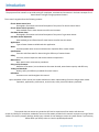
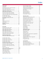
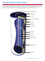
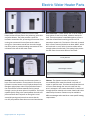
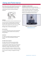
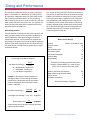
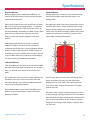
Residential
Water Heater
Training
www.university.hotwater.com
February 2015
Introduction
The purpose of this manual is to provide training for employees, associates and consumers in the basic concepts of residential electric and gas storage type water heaters.
This manual is organized into the following sections:
Electric Water Heater Parts
Photographs, illustrations and a brief description of the parts of an electric water heater.
Electric Water Heater Operation
How standard electric water heaters transfer heat into water.
Gas Water Heater Parts
Photographs, illustrations and a brief description of the parts of a gas water heater.
Gas Water Heater Operation
How standard gas and Flame Guard® water heaters transfer heat into water.
Applications
Types of water heaters available and their application.
Water
Common potable water sources and how water impurities affect a water heater.
Specifications
Formulas and information for determining the efficiency of a water heater.
Safety
Corrosion, thermal expansion and excessive water temperatures.
Maintenance
Basic water heater maintenance procedures.
Sizing and Performance
Definition of hot water, how to determine hot water demand, water heater capacity and efficiency.
Testing and Standards
Quality, safety and efficiency standards for water heaters.
Definitions
Common terms used throughout this manual.
Upon completion of this manual, the reader should have a basic understanding of electric and gas water heater
operations, applications, performance, service issues, safety issues and industry standards.
This manual does not assume any particular skill level or experience of the reader. AOS does not
accept any liability for incomplete, outdated or incorrect information provided in this manual. Improper servicing of water
heaters can result in property damage, bodily injury or death. Do not attempt to service any water heater if you have any
doubt about your ability to do so. Consult a qualified professional.
Copyright© by AOS 2015. All rights reserved.
Index
Section Index
Introduction ................................................................
Standard Electric Water Heater Illustration ................
Electric Water Heater Parts .........................................
Energy Smart II Water Heater Illustration ..................
Energy Smart II Heater Parts ......................................
Electric Water Heater Operation .................................
Standard Gas Water Heater Illustration ......................
Flame Guard® Water Heater Illustration .....................
Flame Guard® Water Heater Series 100 Illustration ..
Gas Water Heater Parts...............................................
Gas Water Heater Operation ......................................
Gas and Electric Water Heater Parts ..........................
Applications .................................................................
Water ..........................................................................
Safety...........................................................................
Sizing and Performance ...............................................
Specifications ..............................................................
Testing and Standards .................................................
Definitions ...................................................................
Topic Index. .................................................................
2
4
5
7
8
9
12
13
14
15
18
24
26
30
32
36
39
40
42
45
Photo Index:
Standard Electric Water Heater ..................................
Electric Water Heater Jacket .......................................
Electric Water Heater Insulation .................................
Electric Water Heater Tank .........................................
Electric Water Heater Element....................................
Electric Water Heater Control Circuit ..........................
Energy Smart II Electric Water Heater ........................
Standard Gas Water Heater ........................................
Flame Guard® Water Heater .......................................
Flame Guard® Water Heater Series 100 .....................
4
5
5
5
5
6
7
12
13
14
Gas Water Heater Jacket .............................................
Gas Water Heater Insulation .......................................
Gas Water Heater Tank and Flue ................................
Gas Water Heater Burner ............................................
Gas Water Heater Venting ..........................................
Gas & Electric Water Heater Dip Tube ........................
Gas & Electric Water Anode Rod .................................
Gas & Electric Water Heater T&P Valve ......................
Gas & Electric Water Heater Drain Valve ....................
Heat Traps ...................................................................
Flames on Flame Trap .................................................
Flame Guard® Thermal Cutoff Switch .........................
Flame Guard® Lint Shedding .......................................
Lowboy Water Heater .................................................
Table Top Water Heater ..............................................
Tiny Titan® Water Heater ............................................
Mobile Home Water Heater ........................................
15
15
15
16
16
25
25
25
25
24
20,22
21,23
22
26
26
27
27
Copyright© by AOS 2015. All rights reserved.
Direct Vent Water Heater .......................................
Power Vent Water Heater .......................................
Power Direct Vent Water Heater ............................
Suspended Solids in Water ......................................
Milky Water .............................................................
Scale on Elements ...................................................
Depleted Anode Rod ...............................................
Electric Reset Button ...............................................
Flame Guard® Lint Filter ..........................................
28
29
29
30
30
31
32
34
36
Illustration Index:
How an Electric Water Heater Works ..................... 9
Standard Gas Valve Front View ............................... 21
Standard Gas Valve Side View ................................. 21
How a Gas Water Heater Works ............................. 21
Flame Guard® Gas Valve ......................................... 21,23
Honeywell Gas Valve Front View…………………………. 23
Honeywell Gas Valve Side View .............................. 23
Heat Traps ............................................................... 24
Atmospheric Venting ............................................... 27
Venting Types .......................................................... 28
Direct Venting .......................................................... 28
Power Venting ......................................................... 29
Power Direct Venting .............................................. 29
Lime Deposit Chart .................................................. 31
Galvanic Corrosion .................................................. 32
Collapsed Flue ......................................................... 33
Expansion Tanks ...................................................... 33
Common Water Temperatures by Application ....... 35
Scald Warning Label ................................................ 35
T&P Valve Operation ............................................... 36
Residential Water Heater Sizing Guide ................... 38
Standby Heat Loss ................................................... 39
Energy Guide Label .................................................. 41
Formula Index:
Gas Recovery Capacity ............................................
Electric Recovery Capacity ......................................
Percentage of Hot Water Required .........................
Water Use Per Activity ............................................
38
38
38
38
3
Standard Electric Water Heater
This section provides an overview of electric water heaters. The first part of this section has illustrations, photographs and a brief
description of each part. The second part of this section describes the operation of standard electric water heaters. When this section
is completed, the reader should have a basic understanding of how an electric water heater transfers heat into water.
Hot Water Outlet
Cold Water Inlet
Junction Box
Non-CFC Foam Insulation
T&P Valve
Reset Button
Thermostat
Outer Jacket
Dip Tube
Anode Rod
Glass Lined Tank
Heating Element
Drain Valve
Copyright© by AOS 2015. All rights reserved.
Electric Water Heater Parts
Outer Jacket - The outer jacket of an electric water
heater consists of three pieces: the jacket top, jacket skirt
and jacket bottom. The jacket provides a space for
insulation around the tank, preventing the consumer from
coming into contact with hot surfaces and to reduce
energy loss. Connections extend from the tank through
the outer jacket to provide plumbing connections for the
cold water inlet and the hot water outlet.
Glass Lined Tank - A water heater tank is constructed of
three pieces of steel: a top head, a bottom head and a
shell. These three pieces are welded together to form a
tank that will withstand a working pressure of 150
pounds per square inch. The interior of the tank is coated
with a ceramic material, baked on at about 1600°F, which
will not break or crack, unless it receives a blow severe
enough to dent the steel tank. This coating helps protect
the tank from the corrosive effects of hot water.
Incoloy Element
Polyester
Foam Dam
Plated Copper Element
Insulation - Between the tank and the outer jacket is a
layer of thermal insulation. Three materials are used as
insulation in water heaters: non-CFC polyurethane foam,
fiberglass and polyester. Non-CFC polyurethane foam is
the more efficient of these materials and is injected
through a port in the outer jacket in liquid form. This liquid
expands quickly filling in the space between the tank and
jacket and then dries. Polyester or fiber-glass is used
around all openings and controls to ensure that the
non-CFC polyurethane foam does not cover these devices.
Copyright© by AOS 2015. All rights reserved.
Element - The element consists of an inner wire
surrounded by filler material enclosed in a sheath of
copper or stainless steel. The thermostat allows electrical
current to flow through the inner wire and from the
wire’s resistance it also creates heat which is transferred
through the filler material to the outer sheath and is then
absorbed by the water. Elements may be available in
different wattages and materials to meet specific heating
requirements.
5
Standard Electric Water Heater Parts
Control Circuit - The standard single-phase control circuit consists of a high limit control switch with a reset button,
upper thermostat, lower thermostat, two heating elements and wires. The upper thermostat first sends electrical
energy to the upper element until the water temperature in the upper third of the tank reaches the thermostat
setting. Power is then transferred to the lower element until the remaining water reaches the lower thermostat
setting. If the water temperature exceeds 170°F the high limit control switch will trip shutting off power to the
elements. Single element water heaters have one element mounted at the bottom of the tank controlled by a single
thermostat and high limit switch.
TOD Wiring Diagram
APCOM Wiring Diagram
Lower
Thermostat
Lower
Element
Black
Black
Yellow
Upper
Element
Yellow
Yellow
Upper
Element
Blue
Blue
Yellow
Blue
Red
Black
Reset
Button
Black
Red
Reset
Button
Upper
Thermostat
&
High Limit
Control
Lower
Element
Copyright© by AOS 2015. All rights reserved.
Blue
Upper
Thermostat
&
High Limit
Control
Energy Smart II Electric Water Heater
Nipple
Heat Trap
Heat Trap
Nipple
Smart Grid
Anode Rod
Dip
Tube
Electronic
Thermostat (ET)
Element
Energy Smart
Module (ESM)
T&P Valve
Thermistor Sensor
Element
Copyright© by AOS 2015. All rights reserved.
Drain Valve
7
Energy Smart Water Heater Parts
Energy Smart® Electric Operation - The Energy Smart® electric water heater includes an Energy Smart Module (ESM) user interface which allows homeowners to easily adjust the temperature, operating mode, and view diagnostic information without requiring any tools or removal of water heater components. The ESM is connected to an Electronic Thermostat (ET) above the upper element. Additionally, the SmartPort located at the top of the water heater on the electrical
junction box is connected and ready for future utility demand response.
Fused Disconnect
or Circuit Breaker
L1
L2
On Junction Box
Cover
Red
Energy Smart Module (ESM)
Black
Black
Red
Green
Smart Grid
Wire Harness
L1
L3
Electronic
Thermostat (ET)
T2
L4
T4
Reset
Button
Element
Black - 2 wires
Yellow
Blue
Temperature Sensor
Electronic Thermostat (ET)
Black
Black - 5 wires
Blue
Element
Energy Smart Module (ESM)
Ground
Screw
Electrical Service
Ground
Copyright© by AOS 2015. All rights reserved.
Electric Water Heater Operation
Standard Electric
The standard residential electric water heater control
circuit consists of a manual reset high limit switch, an
upper thermostat, lower thermostat, two heating
elements and wires.
When the upper third of the tank is heated to the
temperature set on the upper thermostat, power is
switched to the lower heating element. The lower element
continues to heat until the water temperature in the lower
portion of the tank is heated to the lower thermostat
setting.
Copyright© by AOS 2015. All rights reserved.
When power is initially turned on to the unit, the upper
element is energized and heats the water in the upper
third of the tank.
As hot water is drawn from the top of the tank, the dip
tube delivers cold water to the bottom of the tank.
9
Electric Water Heater Operation
When installing a new electric water heater or following
draining the tank for maintenance purposes, the tank
should be completely re-filled before applying power to
the elements. Energizing a heating element that is not fully
submerged in water is referred to as "dry firing," and will
cause the element to immediately burn out.
New element
Dry Fired
Eventually the cold water mixes with the hot lowering the
temperature to below the lower thermostat setting and
the bottom element is energized. If enough water is drawn
to cool the upper third of the tank, the upper thermostat
will send power to the upper element first. When the
upper third of the tank is heated, power will again be
switched to the lower element.
If the upper element burns out, the water heater will
cease to function because the upper thermostat will never
be satisfied and power will never be switched to the lower
element.
If water temperature in the tank reaches 170°F, the
manual reset high limit switch will be tripped. This switch
can be reset by firmly pushing the red button above the
upper thermostat. (See photo and wiring diagram on page
7.)
Single element water heaters have one element mounted
at the bottom of the tank controlled by a single
thermostat and high limit switch.
Copyright© by AOS 2015. All rights reserved.
Notes
Copyright© by AOS 2015. All rights reserved.
11
Standard Gas Water Heater
This section provides an overview of gas water heaters. The first part of this section has illustrations, photographs and a
brief description of each part. The second part of this section describes the operation of standard gas water heaters and
Flame Guard® gas water heaters. When this section is completed, the reader should have a basic understanding of how a
gas water heater transfers heat into water.
Cold Water Inlet
Draft Hood
Hot Water Outlet
(Not shown)
T&P Valve
Outer Jacket
Glass Lined Tank
Flue
Flue Baffle
Dip Tube
Anode Rod
Non-CFC Foam
Insulation
Gas Valve
Drain Valve
Pilot
Thermocouple
Burner
Copyright© by AOS 2015. All rights reserved.
Flame Guard® Water Heater
Cold Water Outlet
(Not Shown)
Draft Hood
Hot Water Inlet
(Not shown)
T&P Valve (Outside not shown)
Outer Jacket
Non-CFC Foam Insulation
Glass Lined Tank
Flu Baffle
Baffle
Dip Tube
Anode Rod
Piezo Igniter
Gas Valve
Drain Valve
Burner
Thermal Sensor
Thermocouple
Pilot
Flame Trap
Copyright© by AOS 2015. All rights reserved.
13
Flame Guard® Water Heater Series 100
Heat
Trap
Heat Trap
T&P Valve
Dip
Tube
Gas Valve
Flue
Baffle
Anode Rod
Copyright© by AOS 2015. All rights reserved.
Gas Water Heater Parts
Outer Jacket - The outer jacket of a gas water heater
consists of three pieces: the jacket top, jacket skirt and
jacket base assembly. The jacket provides a space for
insulation around the tank. The jacket base assembly is
where combustion takes place, and it is designed to shield
the floor from excessive temperatures.
Tank and Flue - In addition to the top head, bottom head
and shell, the gas water heater also has a flue running
through the center. As combustion occurs below the
bottom head, heat rises into the flue. The flue contains a
baffle which is designed to increase the transfer of heat
along the flue pipe and decrease the temperature of
gasses as they exit. Both the tank and the flue are glass
coated to prevent corrosion. On Flame Guard® water
Heaters, the flue is coated on both the inside and outside.
Insulation - Gas water heaters are foam insulated to
prevent heat loss. A fiberglass blanket is used around the
combustion chamber due to the high temperatures
radiated through the combustion chamber walls during
burner operation. Foam insulation could not withstand
these high temperatures. Non-CFC polyurethane foam is
injected through a port in the outer jacket in liquid form
to insulate the remainder of the water heater. This liquid
expands quickly, filling the space between the tank and
jacket when cured, to reduce standby heat loss.
Copyright© by AOS 2015. All rights reserved.
15
Gas Water Heater Parts
Honeywell Gas Valve
Gas Valve– the gas valve has 2 functions. The first function
is to regulate the gas pressure down to a usable level for a
controlled and safe burn. The second function is to regulate the water temperature based on the set point.
Venting - The combustion process creates by-product
gasses such as carbon dioxide, carbon monoxide and
nitrogen oxide. These gasses are harmful to breathe and
need to be vented outside of the home. On standard gas
models a draft hood is positioned at the top of the flue.
The draft hood prevents the backflow of air, called a back
draft, into the flue. A back draft could interfere with
proper venting of harmful gasses and could blow out the
pilot light or burner. Some models use direct, power or
power direct venting to exhaust flue gasses. See page
21-23 for details. Water heaters can be vented in
combination with gas furnaces, heaters and boilers but not
with gas cooking appliances, clothes dryers or
incinerators.
Standard Gas Burner
Flame Guard® Burner
Burner - The burner is centered under the bottom head
and flue. Gas is ignited at the burner by the pilot light. The
resulting combustion transfers heat to the water through
the bottom head and the flue. Gas water heaters burn
either natural gas or propane (also known as L.P., for
Liquid Propane) fuel.
Copyright© by AOS 2015. All rights reserved.
Notes
Copyright© by AOS 2015. All rights reserved.
17
Gas Water Heater Operation
The heat from the pilot flame creates an electrical
current in the thermocouple circuit that operates a small
spring-loaded electromagnet in the gas valve. The
Electromagnet holds the main gas supply line
interrupter open allowing gas to flow to the pilot and
main burner. If the pilot goes out, the electromagnet will
no longer receive a current and the spring loaded
interrupter will shut off the gas supply.
If the pilot is lit, the gas valve’s thermostat controls gas
flow to the main burner. The thermostat’s sensor is a
probe about 6 inches long. It is mounted to the back side
of the gas valve and is inserted inside the water heater
when the gas valve is installed. A knob on the front of the
gas valve allows the user to adjust the temperature.
Standard Gas Water Heaters
In order for a standard gas water heater to operate, the
pilot must be lit.
An energy cut off (ECO) switch is mounted inside the
probe attached to the back of the gas valve and extends
inside the water heater. The ECO functions as a high limit
switch. If water temperature inside the tank reaches about
180°F, the ECO disables the water heater. The entire gas
valve must be replaced if this happens
Copyright© by AOS 2015. All rights reserved.
Gas Water Heater Operation
Air for combustion passes through
the bottom of the water heater
into the combustion chamber. Gas
flows into the burner and is ignited
by the pilot flame.
As the heated water rises, cooler
water sinks to the bottom of the
tank.
Copyright© by AOS 2015. All rights reserved.
Heat from combustion rises
and contacts the tank bottom
head being transferred through
the steel into the
water.
The flue pipe carries away
combustion by product gasses
as well as acting as a heat
transfer surface. At the center
of the flue is a baffle. The baffle
helps transfer heat by
deflecting hot combustion
gasses against the sides of the
flue where the heat is
transferred into the water.
19
Gas Water Heater Operation
Flame Guard® Water Heaters
Spills of gasoline or the presence of other flammable vapors near a standard gas water heater can be very dangerous. The American National Standards Institute (ANSI)
now requires all residential water heaters to be flammable vapor ignition resistant (FVIR). All American Flame
Guard® Water Heaters are fully compliant with ANSI
FVIR standards.
Flame Guard® water heaters have a sealed combustion
chamber. Combustion air and flammable vapors can only
enter through a specially designed flame trap. The flame
trap is located in the bottom of the combustion chamber,
under the main burner and pilot flame. If flammable
vapors are present, the pilot or main burner immediately
ignites them inside the combustion chamber. The vapors
burn on top of the flame trap and are prevented from
escaping back into the room. When the vapors become
too rich or too lean to burn, they snuff themselves out.
A second part of the ANSI Standard concerns resistance
to lint, dust, and other debris build- up on the flame trap.
If the flame trap were to become clogged, combustion air
would be reduced, starving the burner of oxygen. This
may increase the amount of carbon monoxide and create
a health hazard. Flame Guard® water heaters are
designed to reduce lint build-up. The small pressure wave
created by lighting the burner during normal operation
helps blow accumulated lint off the flame trap. If lint does
build up, the thermal cutoff switch will shut down the
heater, so the flame trap and the filter may be cleaned.
Copyright© by AOS 2015. All rights reserved.
Gas Water Heater Operation
The control circuit for a Flame Guard® water heater is
similar to a standard gas water heater. The main
difference is the addition of a resettable thermal cutoff
switch to the thermocouple circuit.
If flammable vapors are ignited they will trigger the
thermal switch, cutting off the gas supply to the pilot and
burner. This prevents the vapors from being reignited
after they have self-extinguished.
Copyright© by AOS 2015. All rights reserved.
Insufficient combustion air supply or blocked ventilation
can also activate the thermal cutoff switch. When these
conditions have been corrected, the thermal switch can
be reset.
21
Gas Water Heater Operation
Series 100 Flame Guard® Water Heaters
Spills of gasoline, or the presence of other flammable
vapors, near a standard gas water heater can be very
dangerous. The American National Standards Institute
(ANSI) now requires all residential water heaters to be
flammable vapor ignition resistant (FVIR). All American
Flame Guard® Water Heaters are fully compliant with
ANSI FVIR standards.
Series 100 Flame Guard® water heaters have a sealed
combustion chamber. Combustion air and flammable
vapors can only enter through a specially designed flame
trap. The flame trap is located in the bottom of the
combustion chamber under the main burner and pilot
flame. If flammable vapors are present, the pilot or main
burner immediately ignites them inside the combustion
chamber. The vapors burn on top of the flame trap and
are prevented from escaping back into the room. When
the vapors become too rich or too lean to burn, they
snuff themselves out.
A second part of the ANSI Standard concerns resistance
to lint, dust, and other debris build-up on the flame trap.
If the flame trap were to become clogged, combustion air
would be reduced starving the burner of oxygen. This
may increase the amount of carbon monoxide and create
a health hazard. Flame Guard® water heaters are
designed to reduce lint build-up. The small pressure wave
created by lighting the burner during normal operation
helps blow accumulated lint off the flame trap. If lint does
build up, the thermal cutoff switch will shut down the
heater, so the flame trap and the filter may be cleaned.
Copyright© by AOS 2015. All rights reserved.
Gas Water Heater Operation
In order for a Series 100 Flame Guard® water heater to
operate, the pilot must be lit. The heat from the pilot
flame creates an electrical current in the thermopile. The
thermopile generates the power needed to operate the
electronic gas control without requiring an external power
source.
A temperature limit switch or ECO (Energy Cut Off) sensor
located in the gas control valve is used to shut off the
water heater if the water temperature exceeds 189°F
(87°C) for 155°F models or 199°F (93°C) for 180°F models.
The electronic gas control incorporates an LED status
indicator with advanced self diagnostic features. The electronic Gas Valve monitors the operation of the heater and
will flash an error code if it identifies an issue.
Insufficient combustion air supply or blocked ventilation
can also activate the thermal cutoff switch. When these
conditions have been corrected, the thermal switch can
be reset.
Copyright© by AOS 2015. All rights reserved.
23
Gas and Electric Water Heater Parts
Heat Traps
In some models, a heat trap is installed at the hot water outlet and cold water inlet to reduce standby heat loss.
The heat trap saves energy by preventing hot water in the tank from rising into the plumbing lines.
Heat traps can be installed internally or externally.
Bottom
Top
Heat Trap Installed on Cold Water Inlet
External Flap-Type Heat Trap Fitting
External Flap-Type Heat Trap Fitting
Tank
Tank
Exterior fittings have a rubber flap that settles in place
to stop hot water from rising into the lines. The flaps
are forced open when hot water is drawn from the
tank.
Interior silicone baffles are slit, with four flaps that
settle into place to stop hot water from rising into the
lines. The flaps are forced open when hot water is
drawn from the tank.
Copyright© by AOS 2015. All rights reserved.
Gas and Electric Water Heater Parts
Anode Rod - The anode rod is a sacrificial part installed to
reduce tank corrosion. A tank full of hot water acts very
much like a battery with small electrical currents flowing
between the different types of metals. The anode rod is
made of aluminum or magnesium which is more
conductive than the steel of the tank. The electrical
currents corrode the anode rod rather than the tank.
Dip Tube - The dip tube moves incoming cold water to the
bottom of the tank. This process sometimes causes
condensation of flue gasses to occur which can cause a
sizzling sound when water droplets fall onto the burner
below. This occurrence is not detrimental to the operation
of the water heater.
T&P Valve - The T&P, or
temperature and pressure relief
valve, is a safety device designed to
relieve excessive pressure on the
tank preventing it from bursting.
This valve also activates to cool the
tank by discharging water if the
temperature inside the tank reaches 210°F. The T&P valve
must never be altered, restricted, or blocked as this
creates a hazardous situation where the tank could build
up pressure and possibly burst.
Drain Valve - The child-resistant drain
valve is located near the bottom of the
water heater and provides a way to
drain the water from the heater for
maintenance purposes.
Copyright© by AOS 2015. All rights reserved.
Combination Dip Tube - The combination dip tube combines the Dip tube and nipple into one part The combo dip
tube moves incoming cold water to the bottom of the
tank. This process sometimes causes condensation of flue
gasses to occur which can cause a sizzling sound when water droplets fall onto the burner below. This occurrence is
not detrimental to the operation of the water heater.
25
Applications
Selecting the right type of water heater depends on the
application. The amount of electrical power available, the
ability to run vent pipe, as well as the size and shape of
the installation area should be considered when selecting
a water heater.
Electric Water Heaters
For an electric water heater it is important to know the
voltage available. This is usually 240 Volts or 120 Volts.
Connecting a 120 Volt water heater to a 240 Volt power
supply will result in the elements burning out
immediately. Connecting a 240 Volt water heater to a 120
Volt power supply will result in very little hot water being
generated. When replacing an existing water heater,
replace it with one of the same voltage and wattage.
The diameter and height of the installation area must also
be considered. Some models are specifically designed for
space constrained areas.
Lowboy models are designed for installation in areas with
height restrictions such as under stairs or counter tops or
in crawl spaces.
For kitchen installations, a 24” wide Table Top model can
be installed as part of a standard 36” high counter top.
Copyright© by AOS 2015. All rights reserved.
Applications
Gas Water Heaters
Failure to properly vent a gas water heater can cause an
explosion, fire or carbon monoxide poisoning. All gas
water heaters must be vented according to the National
Fuel Gas Code. Venting decisions will depend on the
location inside the house where the water heater is to be
installed. If replacing an existing unit, the vent diameter of
the new unit must not exceed the vent diameter of the old
unit, or new venting must be installed. Atmospheric
venting, direct venting, power venting and power direct
venting are all options to be considered.
Point of use models, like the Tiny Titan®, are small
capacity models designed for installation under the sink or
counter top. They provide small amounts of hot water for
hand washing or other small capacity needs. The 2.5
gallon Tiny Titan uses a standard 120 Volt line cord which
can be plugged into any standard grounded outlet.
Atmospheric venting is the most common type used. It is
terminated into a chimney or through the roof. Double
wall pipe is recommended and should be installed in a
manner that avoids unnecessary bends which create
resistance to the flow of vent gasses.
The buoyancy of hot combustion gas rising through the
flue, draft hood and vent pipe allows the water heater to
be vented without mechanical assistance.
Mobile Homes
Mobile homes require a model that is specifically designed
and HUD approved for that type of installation. Some
mobile home models have side-located water connections
in order to connect to water lines located under the floor.
Copyright© by AOS 2015. All rights reserved.
27
Applications
Direct vent water heaters also depend on the buoyancy of
hot combustion gasses for proper venting but are
generally used where vertical venting is not possible or
desirable. Because they draw their combustion air from
outside the structure, they do not waste conditioned air
from inside. The most important consideration with direct
venting is that the water heater must be located very
close to an exterior wall.
Direct Vent
All combustion air is drawn from
outside the home and exhaust
gas is vented to outside using a
concentric vent.
Power Vent
All combustion air is drawn from
inside the home and exhaust gas
is power vented to the outside
using PVC pipe.
Direct vent water heaters use concentric venting.
Combustion air is drawn from outside through a
5” diameter vent pipe. Combustion gasses are vented to
outside through a 3” diameter pipe.
Power Direct Vent
All combustion air is drawn from
outside the home, and exhaust
gas is vented outside, often via
PVC pipe. A concentric vent or
separate pipes can be used.
Atmospheric Vent
All combustion air is drawn from
inside the home and exhaust gas
is vented using metal pipe.
Copyright© by AOS 2015. All rights reserved.
Applications
Power venting is used when the water heater has to be
installed in an interior location of the structure and a long
horizontal vent pipe must be used. The vent pipe can run
from 40 feet to as much as 120 feet, depending upon the
vent pipe diameter, Btu output of the water heater, and
the number and type of bends in the vent pipe. Power
vent water heaters have a motorized blower located at
the top of the flue that forces combustion by-products to
outside the home. Electricity is required to operate the
blower motor.
Power direct venting combines the best features of
power venting and direct venting. Power direct vented
water heaters pull combustion air from outside, but
because they use a motorized blower to exhaust
combustion by-products, they can be installed in interior
locations using long runs of pipe. They can be concentric
vented, or two separate pipes can be used.
The PV and PDV models may be vented with PVC, ABS, or CPVC pipe.
Copyright© by AOS 2015. All rights reserved.
29
Water
The two main sources of water are surface water and
ground water. Surface water comes from lakes, streams
and reservoirs. Ground water comes from wells. Water
sources usually contain some impurities. Most are
harmless to people, but some can damage a water heater
over time.
0 Seconds
Suspended Solids
Surface water is more likely to contain suspended solids,
such as sand, dirt, silt, clay, algae and decaying vegetation.
These suspended solids can make water appear murky, or
they can be microscopic and not easily visible. Suspended
solids will cause staining of sinks, fixtures and clothing. A
mechanical filtering system can be installed to remove
suspended solids.
Dissolved Gasses
Ground water is more likely to contain dissolved gasses
such as hydrogen sulfide. When water containing
hydrogen sulfide is heated, it produces conditions
favorable to the growth of sulfate reducing bacteria. This
bacteria is harmless but will cause a distinct “rotten egg”
smell which is particularly noticeable with the first hot
water usage of the day such as a morning shower. This
problem can usually be eliminated by replacing the anode
rod with one made of a slower acting material and
flushing the water heater with chlorine bleach to kill the
bacteria.
5 Seconds
Other dissolved gasses, such as oxygen and chlorine may
cause water discoloration. This condition is usually
referred to as milky water because the hot water has a
whitish color when initially drawn from the tap. When
left standing for a few minutes, the water will become
clear as the gas bubbles dissipate. This condition is
harmless but can be improved by installing aerated
faucets.
When the hot water system has not been used for an
extended period of time, such as while away on vacation,
hydrogen gas may be produced. Hydrogen gas is
extremely flammable and will ignite when exposed to a
spark or flame. To prevent the possibility of injury, the hot
water faucet at the kitchen sink should be opened for
several minutes before using any electrical appliance in
the immediate vicinity. If hydrogen gas is present, there
will be an unusual sound such as air escaping through
the faucet as water begins to flow.
Copyright© by AOS 2015. All rights reserved.
Water
Hard Water
Hard water contains dissolved calcium and magnesium
and is harmful to all water heaters. Calcium and
magnesium combine with other elements in the water and
form salts which build up as scale. Scale is sometimes
referred to as lime deposits. Hard water is most noticeable
as a hard-to-remove soap scum on tubs and other
bathroom fixtures or as very low sudsing when using
detergents. When water is heated, it becomes less dense
allowing scale to deposit at a higher rate.
In gas water heaters, scale builds up on the tank bottom
head causing small pockets of water and air to be trapped
which promotes corrosion. During the heating process,
water between the layer of accumulated scale and the
bottom head will superheat flashing to steam and causing
popping noises. Accumulated scale acts like insulation on
the inside of the bottom head resulting in overheating. The
stress of being repeatedly overheated will eventually
cause the tank bottom head to leak.
A chemical water softener can be installed to correct hard
water problems, but chemical water softeners substitute
sodium ions for calcium and magnesium ions making the
water more corrosive. This will also shorten the life of the
tank.
In electric water heaters, scale builds up on the heating
elements reducing their ability to transfer heat to the
water. This causes the elements to repeatedly overheat
stressing the element’s outer sheath and causing it to
crack or split
Copyright© by AOS 2015. All rights reserved.
Iron and Manganese
Some water sources may contain iron and manganese.
When iron comes in contact with oxygen it turns red or
brown. When manganese oxidizes it turns black or brown.
Iron and manganese will stain clothing, bathtubs and
plumbing fixtures. Both substances can cause water to
taste and smell foul. Iron and manganese also combine
with bacteria to create a slimy, gelatinous substance that
can clog pipes and filter screens. Iron and manganese
problems can be improved by installing a mechanical
filtering system.
31
Safety
As water is heated, it becomes more corrosive and
expands. These two conditions can create safety issues,
but modern water heaters are designed with features to
insure safe operation. These concepts and other safety
issues will be covered in this section.
Galvanic Corrosion
A water heater is very much like a large battery. Water is
conductive allowing electrical current to pass through it.
High concentrations of dissolved minerals and an acidic pH
can increase water conductivity.
A water heater tank is made from different types of metal
with the tank being steel, the elements being copper, and
fittings which may be brass, steel, galvanized steel or
plastic
The material that the current flows from is called the
anode. The material that the current flows to is called the
cathode. The anode’s surface will corrode. This process is
called galvanic corrosion.
The inside of the tank is lined with a glass coating to
prevent galvanic corrosion. The coating is sprayed on in a
liquid form, dried at about 300°F, then fired at about
1,600°F to fuse the glass to the steel. Although the glass
lining provides excellent protection from galvanic
corrosion, small unprotected areas may still exist such as
the inside of fittings welded to the tank.
To protect any vulnerable areas of the tank, an anode rod
is installed. The anode rod is a sacrificial part made of aluminum or magnesium. Electrical current will flow from the
anode rod to the tank providing cathodic.
Over time the anode rod will corrode away and will need
to be replaced.
Small electrical currents flow between these different
types of materials using the water as a conductor.
Another way to help protect the tank against galvanic
corrosion is by installing dielectric water connections.
Dielectric connections break the electrical circuit between
the tank and the home piping. Dielectric connections
provide the most benefit in older homes where galvanized
pipes were installed. Newer homes usually have copper or
plastic pipes which are less susceptible to galvanic
corrosion.
Copyright© by AOS 2015. All rights reserved.
Safety
Thermal Expansion
Water expands as it is heated. For example, 30 gallons of
water expands to 30 ½ gallons as it is heated from 40°F to
120°F. Water cannot be compressed, so it will cause
pressure to build up in the tank if no expansion area is
provided.
In older water systems, expanding water flows from the
heater back into the supply line preventing pressure build
up. But due to new code restrictions, many areas now
require a check valve between the residence and the
incoming municipal water supply. The check valve blocks
the flow of water back into the supply line causing
pressure to build up. This is called a closed water system.
A weeping T&P valve or faucets that drip intermittently
indicate a closed water system.
The best solution for closed water systems is the
installation of an expansion tank. Expansion tanks are
designed to absorb expanding water and relieve pressure
on the water heater tank.
The expansion tank has a rubber bladder with one side of
the tank containing air. The air pressure in the tank should
be equal to the incoming cold water pressure.
The T&P valve is designed to be an emergency safety valve
only and should not be used as an operating pressure
relief valve in a closed water system.
As the water is heated and expands, it is forced back into
the expansion tank, compressing the air.
In a gas water heater, excessive pressures can cause the
flue to collapse creating a potentially hazardous
condition. In both gas and electric models, excessive
pressures will eventually cause the tank to fail.
Copyright© by AOS 2015. All rights reserved.
As hot water is used, the compressed air pushes the
expanded water out of the tank. This process repeats as
water is heated and used.
33
Safety
Excessive Temperatures
The T&P valve will also activate when the water
temperature exceeds 210°F. Activation of the T&P valve
for excessive temperatures will result in a large amount of
water being discharged and could indicate a problem with
the control circuit. This problem should be corrected at
once in order to prevent scalding injuries.
Gas water heaters are equipped with an energy cutoff
(ECO) switch. It is designed to shut off the gas supply to
the unit if the water temperature exceeds about 190°F.
The ECO is a single use switch and requires complete
replacement of the entire thermostat if activated.
Electric water heaters are not as subject to stacking as gas
water heaters because, on short draws all the heat
produced by the heating element is transferred to the
water in the bottom 1/3 of the tank and mixes with the
surrounding water. For this reason, electric water heaters
usually do not stack more than about 5°F.
Gas water heaters can stack up to 30°F. Heat from the
burner is transferred through the flue at the top of the
water heater as well as through the bottom head.
Repeated short draws accompanied by short heating
cycles allow the flue to overheat water in the top of the
tank without the thermostat sensing it.
Stacking increases the chance of scald injuries. A mixing
valve greatly reduces the chance of a scalding injury due to
stacking by automatically adjusting the proportion of cold
to hot water as water is drawn from the tank. In homes
where children, elderly people or the disabled are present,
a mixing valve is recommended for general use fixtures.
Electric water heaters have a high limit control switch,
shown above, which will shut off power to the elements if
water temperatures exceed about 170°F. This switch can
be reset by firmly pushing the red reset button located on
the thermostat.
Submerged Water Heaters
When a water heater has been submerged in water, such
as during a flood, it must be replaced. The operating
controls can no longer be considered functionally safe. The
insulation surrounding the unit will have become
saturated and cannot be fully dried out. This will cause the
outer surface of the tank to corrode creating
potentially unsafe operating conditions.
When a series of short draws of hot water are used
from the tank, usually 3 gallons or less, it can artificially
increase the number and frequency of heating cycles. With
each draw, cool water enters the bottom of the tank. The
lower thermostat senses a change in temperature
activating the lower element or burner. Since a short draw
of water does not completely remove all the hot water in
the top of the tank, increasing the number of heating
cycles adds more temperature to water in the top of the
tank. This is called stacking.
Copyright© by AOS 2015. All rights reserved.
Safety
Defining Hot Water
Hot water can be defined in many ways. The most
common way to define hot water is by the application.
Water temperature that is considered hot for one
application may be only warm in a different application
and vice versa.
The following chart shows common temperatures used for
various applications. Two of the most common
temperatures used for residential applications are 105°F
for showers and baths and 120-140°F for laundry
Commercial applications often use much higher
temperatures than residential applications. For example,
when using hot water for sanitizing dishes, the National
Sanitation Foundation (NSF) requires that water be 180°F
Copyright© by AOS 2015. All rights reserved.
Although hot water is defined by its application, it is
important to remember that with higher water
temperatures comes an increased risk of a scalding injury.
Water that is 120°F takes more than 5 minutes to cause a
scald injury. Water that is 160°F can scald in less than one
second. Small children, elderly people and the disabled are
most at risk of scalding injuries. Hot water to general use
fixtures, such as lavatories, showers and bathtubs, should
be limited to 120°F or less. If water of a higher
temperature is required for some applications, a mixing
valve should be installed. The mixing valve, or tempering
valve, mixes cold water with the hot water supplied to
general use fixtures lowering the temperature to within
safe limits.
Hot water can produce first-degree burns within:
120°F (49°C) – more than 5 minutes
130°F (54°C) – in 20 seconds
140°F (60°C) – in 3 seconds
150°F (66°C) – in 1½ seconds
160°F (71°C) – in less than 1 second
35
Sizing and Performance
Water heaters require routine maintenance to ensure they
remain in efficient operating condition. The following
components should be periodically checked, and any
noted maintenance issues should be immediately
addressed.
T&P Valve
The T&P valve should be manually operated at least once a
year to insure that it is working properly. Stand clear of
the outlet and slowly lift and release the lever handle.
Allow the valve to operate freely and return to its closed
position. If the valve fails to reset and continues to
discharge water, it will need to be replaced.
Lint Buildup - Gas Water Heaters
Lint buildup reduces the amount of combustion air
available starving the burner of oxygen. This condition can
increase the amount of carbon monoxide released,
creating a potential health hazard. It is a good idea to
inspect the filter at regular intervals and clean it as
necessary to promote good air flow to the unit.
Maintenance videos are located at
www.Hotwater101.com
Drain and Flush
It is recommended that the tank be drained and flushed
periodically to remove sediment which may build up
during operation.
Anode Rod
The anode rod should be visually inspected every three
years. If it is more than 50% depleted it should be
replaced.
Gas Water Heater Inspection
Gas water heaters should be inspected periodically
according to instructions in the installation manual.
A visual inspection should be made of the venting system,
piping systems, main burner and pilot burner. Look for
obstructions, damage or deterioration of the venting
system. The pilot and main burner should be free of soot
and carbon. Verify that the burner is producing a soft blue
flame. Also look for leaking or damaged water and gas
piping.
Copyright© by AOS 2015. All rights reserved.
Sizing and Performance
Determining Efficiency
To determine how much hot water the heater can produce
and how fast it can produce it, recovery capacity, recovery
efficiency, tank draw efficiency and standby efficiency will
have to be considered.
Recovery Capacity
Recovery capacity is the number of gallons of incoming
cold water per hour the water heater can heat to a specific
temperature. The difference between the incoming cold
water temperature and the hot water produced is called
the temperature rise.
The following formula is used to calculate the recovery
capacity of gas water heaters. Input is measured in BTUs.
A BTU (British Thermal Unit) is the amount of energy
required to heat one pound of water by 1°F.
Input is the rated input of the water heater, as shown on
the rating plate. In this example it is 40,000 BTUs.
Efficiency is the water heater’s recovery efficiency; 75% in
this example. The weight of one gallon of water is 8.25
pounds. A 90°F temperature rise is used in this example:
Calculating Recovery Capacity
in Gallons per Hour for
Gas Water Heaters
Recovery =
(Input x Efficiency)
(8.25 x Rise
Example: A 40,000 BTU gas water heater
that has a 75% recovery efficiency with a
90 degree rise.
Recovery =
(40,000 x .75)
=
(8.25 x 90)
= 40.4 gallons per hour
Copyright© by AOS 2015. All rights reserved.
30,000
742.5
The following formula is used to calculate the recovery
capacity of electric water heaters. Electric water heaters
are considered to be 100% efficient when calculating
recovery capacity.
KW represents kilowatts. The number of BTUs in one KW is
3412. The weight of one gallon of water is 8.25 pounds.
Calculating Recovery Capacity
in gallons per Hour for
Electric Water Heaters
Recovery =
(KW x 3412)
(8.25 x Rise)
Example 1: A 4.5KW electric water heater
at 100% efficiency with a 90 degree rise.
(4.5 x 3412)
15,354
Recovery =
=
(8.25 x 90)
742.5
= 20.7 gallons per hour
Example 2: A 5.5KW electric water heater
at 100% efficiency with a 90 degree rise.
Recovery =
(5.5 x 3412)
(8.25 x 90)
=
18,766
742.5
= 25.3 gallons per hour
The top example shows that 4.5KW at a 90°F rise will heat
20.7 gallons per hour. The bottom example shows that
5.5KW at a 90°F rise will heat 25.3 gallons of water per
hour.
When comparing the results of the previous examples, you
might notice that the gas water heater is capable of
heating water about twice as fast as the electric model.
Gas water heaters have much faster recovery rates due to
their higher BTU input. Higher BTU inputs and higher
wattages decrease recovery time
37
Sizing and Performance
An improperly sized water heater can result in cold bath
water, a cold shower or a dishwasher full of dirty dishes.
An improperly sized water heater can force users to alter
their lifestyles to accommodate it, such as by spacing
shower times farther apart. In order to make sure that the
water heater selected is the correct one, it is important to
know how much hot water will be needed and how fast
the water heater can produce it.
Determining Demand
A simple formula can be used to determine how much hot
water the water heater will be required to produce for a
specific application. After determining the amount of
mixed water required, use the formula to calculate the
percentage of hot water that must be provided. Divide the
amount of hot water required by the tank draw efficiency.
The water heater’s storage must be greater than or equal
to the final number.
Percentage of Hot Water Required
(M-C)
(H-C)
M = Mixed Water Temperature
C = Cold Water Temperature
H = Hot Water Temperature
Hot Water Percentage =
Example: A whirlpool tub holds 62 gallons of
105 degree water. If the incoming cold water
temperature is 40 degrees and the hot water is
store at 140 degrees, what size electric water
heater is required?
Hot Water Percentage =
The number of family members, how many bathrooms,
the number of appliances that use hot water and usage
patterns will need to be determined in order to select
the correct water heater. Appliances such as whirlpool
tubs, dishwashers and washing machines need to be
considered, as well as how many people will be taking
showers and how closely shower times will be spaced.
All of this information goes into calculating peak hour
demand, the amount of hot water used during the
busiest usage time of the day.
Water Use Per Activity
Activity
Shower or Bath
Shave
Wash hands or face
Hand wash dishes
Automatic Dishwasher
Prepare Meal
Wash laundry
Gallons of Hot Water Used
20
2
4
4
14
5
32
Example: The following activities take place
between 7:00 and 8:00 a.m. in order to get a
family of four ready for work and school
Mother and father take showers
Both children wash face and hands
Father shaves
Breakfast preparation
Peak Hour Demand = 55 gallons
(105-40) 65
=
= .65
(140-40) 100
Hot Water from Storage = 62 x .65 = 40 gallons
40
= 50 gallons
.8
A water heater with a 50 gallon capacity would be
required in this example.
Water Heater Size =
Copyright© by AOS 2015. All rights reserved.
40
8
2
5
Specifications
Recovery Efficiency
Recovery efficiency, also called thermal efficiency, is a
measure of the total amount of heat produced that gets
transferred into the water.
Standby Efficiency
Standby efficiency is a measure of how much heat is lost
from the stored water while the water heater is not
heating water .
Electric water heaters have a recovery efficiency of about
98%. This is because the heating element is completely
submerged inside the tank which means that almost all
the heat produced is absorbed by the water. Electric water
heaters are not 100% efficient because a very small
amount of heat may escape through the head of the
element.
Although water heater tanks are surrounded by a layer of
insulation, both electric and gas models will lose a small
amount of heat through their outer jacket. Insulation is
rated in terms of thermal resistance, called R-value, which
indicates the resistance to heat flow. A higher R-value
means better insulating effectiveness.
Standard gas water heaters usually have a recovery
efficiency of 70-85%. Gas water heaters need air for
combustion which takes place in the combustion chamber
below the bottom head. Only about 70-85% of the heat
created by the burner is transferred to the water. The rest
is lost as radiant heat loss or escapes up the flue helping
the water heater vent combustion by-products.
Tank Draw Efficiency
Tank draw efficiency is a measure of the amount of usable
hot water that can be drawn from the tank. As hot water is
used, it is replaced at the bottom of the tank by cold
water.
The temperature of the hot water stored is reduced as the
cold water mixes with it. Water that is 30°F below the
thermostat setting is not considered usable because the
temperature has dropped too much.
Electric water heaters usually have a draw efficiency of
80-90%, while gas water heaters usually have a draw
efficiency of 70-80%.
Copyright© by AOS 2015. All rights reserved.
Electric water heaters primarily lose heat through their
water connections and piping, around thermostats,
heating elements, drain valves, T&P valves and anode
rods. Electric water heaters have less than 1% standby
heat loss per hour.
Gas water heaters mainly lose heat through their flues as
air flows through it picking up heat from the stored water.
Heat will also be lost from the combustion chamber which
must be open to provide air for the combustion process.
Standby heat loss for gas water heaters is typically about
2-4% per hour.
39
Testing and Standards
In addition to high internal quality standards, both gas and
electric water heater models are subject to safety and
efficiency standards set by consumer and government
agencies.
Quality
Quality auditors randomly pull finished water heaters
from the assembly line for examination. The auditor has a
checklist of 88 possible defects which range from minor to
critical. If a critical defect is found, two heaters
immediately before and two heaters immediately after the
audited unit will be pulled and inspected. If any of these
four heaters have defects, four more units will be pulled
and inspected. If any of the second group of four show
defects, the entire lot will be pulled and inspected.
The Engineering Department also randomly pulls units for
testing. These tests are more performance based. They
test first hour rating, BTU output, burner reliability and
other performance issues.
Safety
The American National Standards Institute (ANSI) sets
safety standards for gas water heaters. The Canadian
Standards Association (CSA), formerly known as the Gas
Standards Association (GSA), certifies performance of gas
water heaters to the ANSI standard.
California and Texas have regulations requiring lower
nitrogen oxide (NOx) emissions for natural gas water
heaters than required by federal standards.
Efficiency
The National Appliance Energy Conservation Act
(NAECA) of 1987 was enacted by congress to set national
minimum efficiency standards for gas and electric
appliances. Before 1987 some states were setting
individual efficiency standards. Now the Department of
Energy (DOE) regulates efficiency standards for
residential water heaters.
The yellow Energy Guide label is displayed on each
model and compares that model’s estimated annual
operating cost to other similar models. The DOE has a
standardized test that measures the overall efficiency of
the water heater and translates it into the estimated
annual operating cost shown on the yellow label.
The DOE tests combine tank draw efficiency, recovery
efficiency and standby efficiency. The result is called an
Energy Factor. The DOE also measures First Hour Rating,
which is the amount of usable stored water that is
available combined with how much water can be heated
in one hour. Both the Energy Factor and the First Hour
Rating information is available on the Internet at
http://www.ahrinet.org/
The Underwriter’s Laboratory (UL) sets safety standards
for electric water heaters and certifies performance of
electric water heaters to the standard.
The government department of Housing and Urban
Development (HUD) approves water heaters
manufactured for use in mobile homes.
Copyright© by AOS 2015. All rights reserved.
Testing and Standards
First Hour
Rating
Model
Estimated
Annual
Operating
Cost
Estimated
Yearly
Energy
Use
National
Average
Cost
Per KWH
Copyright© by AOS 2015. All rights reserved.
41
Definitions
American National Standards Institute (ANSI) - Agency
that set standards for safety of gas water heaters.
Anode - Material that current flows from inside a battery.
Anode Rod - Sacrificial part made of aluminum,
magnesium or other compounds that is corroded by
electrical currents in order to protect the inside of the
tank.
Back Draft - The back flow of air into the flue. Usually
caused by negative air pressure in the home or improper
vent termination.
BTU - (British Thermal Unit) The amount of energy
required to heat one pound of water by 1°F.
Carbon Monoxide - Poisonous gas that is a by-product of
incomplete combustion. Carbon monoxide is harmful or
fatal to breathe and has to be vented to the outdoors.
Excessive carbon monoxide is an indication of poor
combustion. The cause must be investigated and
immediately eliminated.
Condensation - Water droplets formed as the temperature
drops below the dew point. The amount of condensation
is affected by the amount of humidity in the air. A
common example is water droplets that form inside the
flue and on the bottom tank head when very cold water is
introduced into a gas water heater. Condensation may
cause a sizzling sound to be heard as the water droplets
fall onto the burner below.
Control Circuit - Parts that measure tank temperature,
direct the unit to begin heating and provide safety controls
to prevent overheating or other unsafe operating
conditions.
Dielectric Connections - Water connectors that stop the
flow of electricity from the house piping to the water
heater.
Dip Tube - Tube that moves incoming cold water to the
bottom of the tank to prevent it from mixing with stored
hot water at the top of the tank.
DOE - (Department of Energy) Government agency that
regulates water heater efficiencies.
Cathode - Material that current flows to inside a battery.
Cathodic Protection - Protection supplied by a
sacrificial anode to prevent corrosion of other parts.
Check Valve - A one-way valve installed to prevent reverse
flow of water in a piping system.
Closed Water System - A water system where a check
valve prevents the flow of expanding water back into the
municipal water supply and includes no provision for
thermal expansion.
Cold Water Inlet Temperature - The temperature of the
water coming from the water supply to the water heater.
Combustion Chamber - Part of the gas water heater,
located in the jacket base assembly, where the burner is
located and combustion takes place.
Drain Valve - Child-resistant valve located near the bottom
of the water heater to provide a way to drain the water
heater for maintenance purposes.
Dry Firing - Energizing a heating element before it is
completely covered in water. Dry firing will cause the
standard heating element to burn out immediately.
Energy Cutoff Switch - (ECO) Gas water heater safety
device that shuts off gas supply to the unit if water
temperature exceeds 180°F. The ECO is a single-use switch
and requires complete replacement of the entire
thermostat if activated.
Energy Factor - Overall efficiency of a water heater
calculated by testing tank draw efficiency, recovery
efficiency and standby efficiency using the DOE protocol.
Copyright© by AOS 2015. All rights reserved.
Definitions
Energy Guide Label - Yellow label displayed on every
water heater that compares that model’s energy use to
similar models.
Expansion Tank - A tank installed on the incoming water
line that absorbs expanding water and prevents pressure
buildup inside the tank.
First Hour Rating - A measure of the amount of usable
stored water that is available combined with the quantity
of water that can be heated in one hour.
Flammable Vapors - Ignitable vapors from liquids such as
gasoline, solvents, liquid propane or butane.
Flue - The vertical pipe in the center of a gas water heater
designed to conduct rising heat into the water and direct
combustion by products out the vent.
Flue Baffle - A device located in the center of the flue that
slows the rising heat and gasses produced by the
combustion process, enabling the water to absorb more
heat.
Galvanic Corrosion - The erosion resulting from electrical
current flow from a noble metal (anode) to a less noble
metal (cathode).
High Limit Control Switch - Electric water heater safety
device that shuts off power to the elements if water
temperature exceeds 170°F. This switch can be reset by
firmly pushing on the red reset button.
Hydrogen Sulfide - Dissolved gas that is sometimes found
in water supplies. When water containing hydrogen sulfide
is heated, it promotes the growth of sulfate reducing
bacteria that produce a “rotten egg” smell.
Insulation - Polyurethane foam, polyester and fiberglass
installed between the tank and jacket that prevent
standby heat loss.
Jacket - Outer covering of the water heater that provides
space for insulation and prevents consumers from
touching hot tank surfaces.
Kilowatt - (KW) Measure of electric power.
1KW = 1,000 Watts.
Milky Water -Water that has small gas bubbles when first
drawn from the tap. The bubbles dissipate when the water
is left standing for a few minutes.
Mixing Valve - (Tempering Valve) Device that mixes cold
water with hot water supplied to general use fixtures in
order to help prevent scalding injuries.
Ground Water - Water that comes from wells.
Hard Water - Water that contains dissolved calcium and
magnesium. Hardness is measured in grains.
National Sanitation Foundation – (NSF) Organization that
sets sanitation standards for the food preparation
industry.
Heat Trap - Devices installed on the incoming, and
sometimes outgoing, water lines to prevent heat from
escaping from the stored hot water.
Nipple -Threaded fittings provided on some models for
incoming and outgoing water pipe connections. Most
models utilize 3/4” water connections.
Heating Element - Part of the electric water heater that
transfers heat to the water, made up of an inner wire
surrounded by filler material enclosed in a copper or
stainless steel sheath.
Nitrogen Oxide - Gas by-product of combustion that is
harmful to the earth’s atmosphere.
Copyright© by AOS 2015. All rights reserved.
43
Definitions
Pilot Light - A small flame that stays lit all the time and
ignites the burner flame.
Potable Water - Water that is suitable for drinking
because it contains nothing harmful.
Radiant Hydronic Heating - Home heating system that
circulates hot water through tubes in the floor or through
baseboard heaters.
Recovery Capacity - The number of gallons of
incoming cold water per hour the water heater can heat to
a specific temperature.
Recovery Efficiency - (Thermal Efficiency) A measure of
the total amount of heat produced by the water heater
that is transferred to the water.
Scale - Salts formed and deposited inside the water
heater or on fixtures. Sometimes referred to as lime
deposits.
Tank - Part of the water heater that holds the stored hot
water. Constructed of welded steel and glass lined to
prevent corrosion.
Tank Draw Efficiency - A measure of the amount of usable
hot water that can be drawn from the tank.
Temperature Rise - The difference between the incoming
cold water temperature and the hot water produced.
Thermal Expansion - Expansion of water as it is heated.
Thermistor - Electronic device used in place of a
mechanical thermostat that measures water
temperature.
Thermocouple - Safety device that generates a small
electrical current used to energize a safety magnet inside
the gas valve.
Thermostat - Device that measures water temperature.
Smelly Water – Usually ground water that contains
hydrogen sulfide gas. The smell is caused by
sulfate-reducing bacteria that thrive under conditions
found inside a water heater.
Usable Hot Water - Water that is less than 20°F below the
thermostat setting.
Stacking - Very high temperatures at the top of the tank
caused by increased cycling of the burner or heating
elements during short draws of water.
Working Pressure - The maximum daily pressure the
water heater is rated for, usually 150psi.
Watt - Measure of electric power. 1,000 Watts = 1 Kilowatt
Standby Efficiency - A measure of how much heat is lost
from the stored water while the water heater is not
heating water.
Surface Water - Water that comes from lakes, streams and
reservoirs.
Suspended Solids - Small particles of sand, dirt, silt, clay,
algae or decaying vegetation that are suspended in water.
T&P Valve - (Temperature and Pressure Relief Valve)
Safety device that releases hot water when
temperatures inside the tank reach 210°F, or when
pressure exceeds 150psi.
Copyright© by AOS 2015. All rights reserved.
Top Index
American National Standards Institute (ANSI) - 22, 40, 42
Anode Rod - 4, 7, 12, 13, 14, 25, 30, 32, 36, 39, 40,42
Atmospheric Venting - 27
Back Draft - 16, 42
Burner - 12, 13, 15-16, 18, 20-26, 34, 36, 39, 40, 42
Calcium - 21, 43
Canadian Standards Association (CSA) - 40
Cathode - 32, 42, 43
Cathodic Protection - 42
Closed Water System - 33, 42
Condensation - 25, 42
Demand - 2, 8, 38
Department of Energy (DOE) - 40, 42
Dielectric Water Connections - 32
Dip Tube - 4, 7, 9, 12-14, 25, 42
Direct Venting - 16, 27-29
Dissolved Gasses - 30
Draft Hood - 12, 13, 16, 27
Drain Valve - 4, 7, 12, 13, 25, 39, 42
Element - 4-10, 26, 31, 32, 34, 39, 42-44
Energy Cutoff (ECO) Switch - 34, 42
Energy Factor - 40,42
Excessive Temperatures - 15, 34
Expansion Tank - 33, 43
First Hour Rating - 40, 43
Flame Guard® Water Heaters - 12-16, 20-23
Flue - 12, 14-16, 19, 29, 33, 34, 39, 42
Flue Baffle - 12, 43
Galvanic Corrosion - 32, 43
Gas Water Heater Inspection - 36
Ground Water - 30, 43
Hard Water - 31, 43
Housing and Urban Development (HUD) - 27, 40
Hydrogen Gas - 30
Hydrogen Sulfide - 28, 41
Insulation - 4, 5, 12, 13, 15, 31, 34, 39, 43
Iron - 31
Lime Deposits - 31
Lint - 20, 22, 36
Lowboy Water Heaters - 26
Magnesium - 25, 31, 32, 42, 43
Manganese - 31
Manual Reset High Limit Switch - 9, 10
Milky Water - 30, 41, 43
Mixing Valve - 34, 35, 43
National Sanitation Foundation (NSF) - 35, 43
Nitrogen Oxide (NOx) - 16, 40, 43
Peak Hour Demand - 38
Percentage of Hot Water Required - 38
Pilot - 12, 13 16, 18, 20, 21-23, 36,44
Power Venting - 27, 29
Recovery Capacity - 37, 44
Copyright© by AOS 2015. All rights reserved.
Recovery Efficiency - 35, 39, 40, 44
R-Value - 39
Scalding - 34, 35, 43
Scale - 31, 44
Single Element Water Heaters - 6, 10
Stacking - 34, 44
Standby Efficiency - 37, 39, 40, 42, 44
Submerged Water Heater - 34
Sulfate Reducing Bacteria - 30, 43, 44
Surface Water - 30, 44
Suspended Solids - 30, 44
T&P Valve - 4, 7, 12-14, 25, 33, 34, 36, 39, 44
T&P Valve Inspection - 36
Table Top Water Heaters - 26
Tank Draw Efficiency - 37-40, 42, 44
Temperature Rise - 37, 44
Thermal Cutoff Switch - 20-23
Thermal Expansion - 33, 42, 44
Thermistor - 7, 44
Thermocouple - 12, 13, 18, 21, 44
Tiny Titan® - 27
Underwriter’s Laboratory (UL) - 40
Venting - 16, 27, 28, 29, 30, 36
Voltage - 26
Water Use Per Activity - 38
45