1
PNC-950
USER'S MANUAL
ROLAND DG CORPORATION
For the USA
FEDERAL COMMUNICATIONS COMMISSION
RADIO FREQUENCY INTERFERENCE
STATEMENT
This equipment has been tested and found to comply with the
limits for a Class B digital device, pursuant to Part 15 of the
FCC Rules.
These limits are designed to provide reasonable protection
against harmful interference in a residential installation.
This equipment generates, uses, and can radiate radio
frequency energy and, if not installed and used in accordance
with the instructions, may cause harmful interference to radio
communications.
However, there is no guarantee that interference will not
occur in a particular installation.
If this equipment does cause harmful interference to radio or
television reception, which can be determined by turning the
equipment off and on, the user is encouraged to try to correct
the interference by one or more of the following measures:
- Reorient or relocate the receiving antenna.
- Increase the separation between the equipment and
receiver.
- Connect the equipment into an outlet on a circuit different
from that to which the receiver is connected.
- Consult the dealer or an experienced radio/TV technician
for help.
Unauthorized changes or modification to this system can void
the users authority to operate this equipment.
The I/O cables between this equipment and the computing
device must be shielded.
Grounding Instructions
Do not modify the plug provided - if it will not fit the outlet,
have the proper outlet installed by a qualified electrician.
Check with qualified electrician or service personnel if the
grounding instructions are not completely understood, or if in
doubt as to whether the tool is properly grounded.
Use only 3-wire extension cords that have 3-prong
grounding plugs and 3-pole receptacles that accept the tool’s
plug.
Repair or replace damaged or worn out cord immediately.
Operating Instructions
KEEP WORK AREA CLEAN. Cluttered areas and benches
invites accidents.
DON’T USE IN DANGEROUS ENVIRONMENT. Don’t
use power tools in damp or wet locations, or expose them to
rain. Keep work area well lighted.
DISCONNECT TOOLS before servicing; when changing
accessories, such as blades, bits, cutters, and like.
REDUCE THE RISK OF UNINTENTIONAL STARTING.
Make sure the switch is in off position before plugging in.
USE RECOMMENDED ACCESSORIES. Consult the
owner’s manual for recommended accessories. The use of
improper accessories may cause risk of injury to persons.
NEVER LEAVE TOOL RUNNING UNATTENDED.
TURN POWER OFF. Don’t leave tool until it comes to a
complete stop.
For Canada
CLASS B
NOTICE
NOTICE
This digital apparatus does not exceed the Class B limits for
radio noise emissions set out in the Radio Interference
Regulations of the Canadian Department of Communications.
CLASSE B
AVIS
Cet appareil numérique ne dépasse pas les limites de la
classe B au niveau des émissions de bruits radio électriques fixés dans le Réglement des signaux parasites
par le ministère canadien des Communications.
KEEP HANDS AWAY WHEN CUTTING TOOL IS IN MOTION.
REGARDEZ BIEN OU` VOUS METTEZ LES MAINS LORSQUE
L' OUTIL DE DECOUPE FONCTIONNE.
CAUTION
1) Unauthorized copying or transferral, in whole or in part, of this manual is prohibited.
2) The contents of this operation manual and the specifications of this product are subject to change without notice.
3) The operation manual and the product have been prepared and tested as much as possible. If you find any misprint or error, please
inform us.
4) We cannot in any way assume any responsibility whatsoever with regard to whatever consequences that may happen subsequent
to the making of changes or alterations to this product. We also cannot in any way assume responsibility for whatever may result
when this product is operated, or with regard to whatever results from making use of any explanatory documentation.
ROLAND DG CORPORATION
1227 Ohkubo-cho, Hamamatsu-shi, Shizuoka-ken, JAPAN 432
MODEL NAME
: See the MODEL given on the rating plate.
RELEVANT DIRECTIVE : EC MACHINERY DIRECTIVE (89/392/EEC)
EC LOW VOLTAGE DIRECTIVE (73/23/EEC)
YEARS OF MANUFACTURE
1995
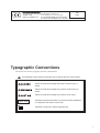
Typographic Conventions
This manual uses certain typographic symbols, outlined below.
This indicates a point requiring particular care to ensure safe use of the product.
: Failure to heed this message will result in serious injury or
death.
: Failure to heed this message may result in serious injury or
death.
: Failure to heed this message may result in minor injury.
NOTICE
: Indicates important information to prevent machine breakdown
or malfunction and ensure correct use.
: Indicates a handy tip or advice regarding use.
i
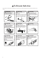
To Ensure Safe Use
If you find some abnormality, immediately turn off the power switch and check the user's manual to find out what is
wrong.
WARNING
Never disassemble or
modify this product.
CAUTION
Handle the power cord
with care.
Do not step on or damage the power
cord, or allow heavy objects to be
placed atop it. Failure to heed this
may result in electrocution or fire.
CAUTION
Do not allow liquids, metal
objects or flammables
inside the machine.
Fire or breakdown may result.
CAUTION
Ensure the safety of the
area around the platen
before switching on the
power.
The carriage moves simultaneously
when the power is switched on.
ON
ii
CAUTION
Do not install in an
unstable or high location.
CAUTION
When pulling the power
cord from an electrical
socket, be sure to grip the
plug.
CAUTION
Handle the blade with care.
Do not installation the machine on
the edge of a table, or it may fall.
CAUTION
Do not inadvertently allow
the hands, hair, or necktie
near the carriage while in
operation.
CAUTION
Do not allow the hands
near the platen while in
operation.
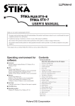
About the Labels Affixed to the Unit
These labels are affixed to the body of this product. The following figure describes the location and content of these
messages.
Do not allow the hands near
the platen while in operation.
Rating plate
iii
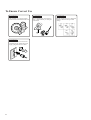
To Ensure Correct Use
NOTICE
NOTICE
This product is a precision instrument and must be handled with care.
NOTICE
When the unit is not in use for an
extended period, detach the power
supply plug from the AC outlet.
3
2
iv
1
Do not install in an area subject to
dust or high humidity or with poor
ventilation.
NOTICE
Do not connect to an AC outlet that
supplies other than the specified
voltage.
Thanks and Best Wishes
Thank you very much for purchasing the CAMM-1 PNC-950.
Since we wish you many years of productive use of your PNC-950, we ask you to read this manual
and make yourself familiar with the PNC-950’s operational procedures and requirements before
running it.
If something seems abnormal, turn OFF the power and reference this manual for answers, tips and
procedures to solving the problem.
TABLE OF CONTENTS
1
2
3
PRECAUTIONS IN USE ................................................................................................................... 2
CHECKING SUPPLIED ITEMS ..................................................................................................... 2
PART NAMES AND FUNCTIONS
• Front View ............................................................................................................................................... 3
• Rear View ................................................................................................................................................ 3
• Operation Panel ....................................................................................................................................... 4
4
BASIC OPERATION
4-1 Setting Up and Connection .................................................................................................................... 5
• Setting Up ................................................................................................................................................ 5
• Connection ............................................................................................................................................... 5
4-2 DIP Switch Settings ............................................................................................................................... 6
4-3 Installing the Blade ................................................................................................................................ 7
4-4 Loading the Sheet - SETUP Key ........................................................................................................... 8
• Turning on the Power .............................................................................................................................. 8
• Loading the Sheet .................................................................................................................................... 8
• Removing the Sheet ............................................................................................................................... 11
• About the Cutting Area ......................................................................................................................... 12
4-5 Setting the Origin Point -
,
,
,
, and ORIGIN SET Keys .......................................... 12
,
,
,
, and TEST Keys ....................................... 13
4-6 Cutting Test to Check Blade Force 4-7 Downloading Cutting Data .................................................................................................................. 14
• Software Settings ................................................................................................................................... 14
• Pausing Cutting Operations - Pause Key, Pause LED and SETUP Key ............................................... 14
• Continuing Cutting ................................................................................................................................ 15
• Cutting a Thick Sheet ............................................................................................................................ 15
4-8 Applying the Completed Cutout .......................................................................................................... 15
4-9 When Cutting Is Completed ................................................................................................................. 16
Performing a Self-test ................................................................................................................................. 16
5
SETTINGS FOR EACH FUNCTION
• Using the Sheet Effectively (Rotate Function) - ROTATE key and ROTATE LED ........................... 17
• Plotting on Paper Media - PEN MODE Key and PEN MODE LED .................................................... 18
6
7
8
9
10
11
12
ABOUT THE BLADE ........................................................................................................................ 19
WHAT TO DO IF... ............................................................................................................................ 20
LIST OF CAMM-GL III INSTRUCTIONS .................................................................................. 22
LIST OF DEVICE CONTROL INSTRUCTIONS ..................................................................... 24
CHARACTER SETS ........................................................................................................................ 26
LIST OF OPTIONS ........................................................................................................................... 27
SPECIFICATIONS OF PNC-950 ................................................................................................ 28
Copyright © 1994 ROLAND DG CORPORATION
1
1 PRECAUTIONS IN USE
• Ensure that the power supply voltage in within +/-10% of the machine's rated voltage.
• Always be careful whenever the unit is in operation, so as not to risk getting fingers or hair caught in its mechanisms.
• Never take apart, or alter the construction of this device.
• Never allow any liquids, metallic objects, or flammable material to get inside the unit.
• When the machine is not in use for an extended period, remove the power supply plug from the AC outlet.
• When pulling the power cord from an electrical socket, be sure to grip the plug to prevent damage to the cord or cause
electrical shorts.
• Handle the power cord carefully to prevent damage. Never step on or place heavy objects on the cord.
• Never move the tool carriage by hand. Damage and performance inaccuracy may result.
• When the unit is not in use, keep the pinch rollers raised. The pinch rollers may be deformed if left engaged.
• Do not subject the machine to bumps, or other severe shocks.
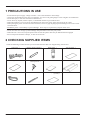
2 CHECKING SUPPLIED ITEMS
Check the following to make sure that you received all the items that were shipped along with the unit.
Power Cord : 1
Blade for Sheet (Carbide) : 1
Blade Holder : 1
Test-use Sheet : 1
Test-use Application Sheet : 1
Test-use Water-based
Fiber-tipped Pen : 1
User's Manual : 1
Sheet Base : 1
Separate Cutter : 1
2
Tweezers : 1
Test-use High-quality Paper
(A3 size) : 1
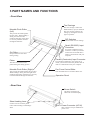
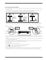
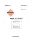
3 PART NAMES AND FUNCTIONS
• Front View
Tool Carriage
Movable Pinch Roller
(Left)
This presses the media against
the grit roller. When loading a
sheet, place the left roller
inside the left edge of the sheet
to correctly track the material
through the machine.
The tool carriage is where the
blade holder (or pen) is mounted.
The tool carriage performs the
cutting by moving the tool left/
right or up/down.
DIP Switches
Used to make various settings.
Serial (RS-232C) Input
Connector
Grit Roller
Grasps and moves the sheet
during cutting.
Platen
In a serial configuration, this
connector is where you need to
connect the serial cable that is
used to communicate with your
computer.
Parallel (Centronics) Input Connector
The sheet is moved over the
platen during the cutting process.
In a parallel configuration, this connector is
where you need to connect the parallel cable in
order to communicate with your computer.
Movable Pinch Roller (Right)
Pen Force Control Slider
This presses the media against the grit roller.
When loading a sheet, place the right roller
inside the right edge of the sheet to correctly
track the material through the machine.
Sets the blade force to be used with the tool.
Operation Panel
• Rear View
Power Switch
ON when switched to [I].
OFF when switched to [O].
Sheet Loading Lever
Used to raise or lower the pinch
rollers when loading or unloading a
sheet.
Power Connector (AC IN)
This connector accepts standard AC
power cord.
3
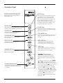
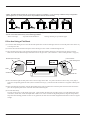
• Operation Panel
* The TEST key and the cursor keys function
only when the SETUP LED is lighted, and
the ROTATE key functions only when the
SETUP LED is not lit.
SETUP Key
After the sheet has been loaded, press this
key to determine the width of the sheet
automatically. Also, pressing this key
after using the PAUSE key to temporarily
stop a cutting operation in progress
thereby deletes the data that has been sent
to the PNC-950 from the computer. This
key must be pressed in order to cut.
SETUP LED
This lights up when the SETUP key is pressed.
Cutting can be performed when this is lit.
PAUSE LED
This lights up when the PAUSE key is
pressed to pause the PNC-950.
PEN MODE LED
This lights up when the PEN MODE
key is pressed.
PAUSE Key
When pressed once, this temporarily halts
cutting in progress. Pressing this key again
releases the paused state.
PEN MODE Key
Press this to perform plotting with a pen on
paper. (Be sure to load a pen in the tool
carriage.)
ROTATE LED
ROTATE Key
This lights up when the ROTATE
key has been pressed.
Pressing this key sets the origin point
at the bottom right of the sheet and
rotates the direction of cutting by 90°.
TEST Key
ORIGIN SET Key
Pressing this key executes a cutting test to
check material characteristics, cut quality,
and suitable pressure for the blade.
Press this key to move and set the
origin point for cutting.
(Cursor Keys)
POWER/ERROR LED
This lights up when the power is
switched on, and flashes when an error
is generated.
4
Use these keys when checking media
alignment, moving the tool carriage for
setting the origin or performing a cutting
test.
The direction of the arrows on the , ,
, and
keys indicates the direction in
which the tool carriage moves in relation to
the sheet. Pressing the
key, for example,
moves the tool carriage to the left, and
pressing the
key moves it to the right.
However, pressing the
or
key does
not actually cause the tool carriage to move
-- instead, the sheet moves. This means that
pressing the
causes the sheet to move
toward the front of the machine, and
pressing the
key makes the sheet move
to the rear.
4 BASIC OPERATION
4-1 Setting Up and Connection
• Setting Up
When arranging setup space for the PNC-950, make sure you have a space that is at least 905 mm (35-11/16") wide, 500
mm (19-11/16") in depth, and 220 mm (8-11/16") in height.
Since the sheet moves during cutting, make sure the unit is placed on a stable, sturdy surface. Also make sure there is
nothing that can block the sheet at both front and rear.
Avoid installing the PNC-950 in the following conditions, as this may result in damage to the machine.
• Avoid places subject to strong electrical noise.
• Avoid excessively dusty or dump places.
• Never leave the unit in a place that is subject to direct sunlight, or where the temperature could go to extremes.
• Since it is normal for this device to emit heat when in operation, never place it where it is poorly ventilated and such
heat cannot dissipate.
• When Moving the PNC-950...
Do not try to pick up or move the PNC-950 by grasping the top area of the unit -- be sure to use both hands to grip the
PNC-950 securely on the left and right sides.
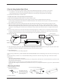
• Connection
* Always make sure that the power is off on both the computer and the PNC-950 whenever any cables are
connected or disconnected.
Power outlet
Power cord
Power
connector
Parallel interface cable
Serial interface cable
Parallel input connector
Serial input connector
Serial connector
or
parallel connector
Cables are available separately. One which you are sure matches the model of computer being used should be selected.
When the PNC-950 is connected to the computer via the serial port, the communication parameters (Baud, Data, Parity,
Stop, etc.) for the PNC-950 need to match the port settings on the computer. Use the DIP switches on the right-hand side
of the PNC-950 to make these settings. Refer to "4-2 DIP Switch Settings" to make the correct settings.
5
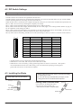
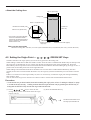
4-2 DIP Switch Settings
DIP switches settings must be made only when the power is turned off.
The DIP switches are located on the right-hand side of the unit.
The DIP switches set the serial port communication parameters, the value for the blade offset, the type of sheet loaded,
and the smoothing function (for cutting smooth circles and arcs).
When the PNC-950 is connected to the computer through the serial port, be sure that the communication parameters for
SW-1 to SW-6 are set correctly, matching the computer port settings.
SW-7, which controls the blade offset, should normally be set to OFF (0.25 mm).
SW-8, which controls the sheet weight, should normally be set to OFF (light). See "Cutting Thicker Sheets" on page 15
for an explanation of the settings for SW-8.
SW-9, which controls the loaded sheet type, should be set to match the sheet that will be used (loaded). Set this to ON
when using a flat sheet (piece), and set it to OFF (roll) when using a rolled sheet.
SW-10, which controls smoothing, should be set to OFF (smoothing on) when you want to cut smooth circles and arcs.
OFF
ON
DIP switch
Function
OFF
ON
1
SW-1
Baud rate
9600
4800
2
SW-2
Parity check
Disable
Enable
3
SW-3
Parity check
ODD
EVEN
4
SW-4
Data bits
8-bit
7-bit
5
SW-5
Stop bits
1-bit
2-bit
6
SW-6
Handshake
Hardwire
XON/XOFF
7
SW-7
Blade offset
0.25
0.5*
8
SW-8
Sheet weight
Light
Heavy
9
SW-9
Sheet size
Roll
Piece
10
SW-10
Smoothing
ON
OFF
*Option required ; please consult your dealer.
• All DIP switches are set to OFF when shipped from the factory.
• When SW-2 is set to OFF, SW-3 may be set to either ON or OFF.
• When SW-8 is set to ON (heavy), cutting speed ranges from 10 cm/sec to 100 cm/sec. This speed is
not exceeded while the switch is at this setting, even if an instruction specifying a cutting speed
greater than 100 cm/sec is sent from the computer.
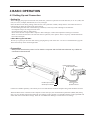
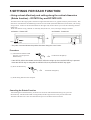
4-3 Installing the Blade
Blade Holder (XD-CH2) Part Names
• Always make sure the power switch is OFF before installing
(or replacing) the cutter.
• Do not touch the tip of the blade with your fingers, as the
cutting performance of the blade will be impaired.
Push-pin
Installing a Blade in the Blade Holder
Scale
Cap
Insert a blade into the blade holder until it
snaps into place with an audible click.
* Take care not to break or chip the blade.
Blade holder
Cutter blade
Blade
6
Push-pin
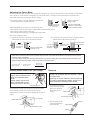
Adjusting the Cutter Blade
The amount of cutter blade extension can be adjusted by rotating the cap. Turn the cap clockwise to retract the blade or counterclockwise to expose it. (Each scale line corresponds to 0.1 mm (about 0.004"). One full turn moves the blade 0.5 mm (about 0.02").)
Adjust blade holder before mounting on the tool carriage.
• If an ordinary sheet is to be used, tighten the cap all the way
(2.5 mm (about 0.098") of blade extension).
Tighten the cap until
there is no gap
Turn the cap
as shown by
the arrow
Amount of cutter blade
extension: 2.5 mm (about
0.098") (maximum length)
• Blade adjustment may be necessary in the following cases:
- When cutting a sheet whose base paper is thinner than its material (sheet portion)
- When cutting a material with no base paper
- When cutting without making any fine adjustment of blade force
Here’s how to adjust the blade.
(1) Turn the cap as shown by the arrow to align the tip of the
blade with the tip of the cap (0 mm of blade extension).
(2) Turn the cap as shown by the arrow to adjust the amount
of blade extension beyond the tip of the cap.
Gap
Turn the cap
as shown by
the arrow
Amount of cutter blade
extension: 0 mm
Turn the cap
as shown by
the arrow
Amount of cutter
blade extension
Thickness of the
sheet portion
Thickness of
the base paper
• Take care to ensure that the amount of blade extension does not exceed the thickness of the sheet portion plus the
thickness of the base paper.
• If you don’t know exactly how thick the sheet portion is, perform a cutting test and gradually extend the blade. The
optimum blade extension leaves a faint score mark on the base paper.
Amount of cutter
Thickness of the
blade extension = sheet portion
+
Thickness of
the base paper
2
Installing a Blade Holder in the Tool Carriage
Removal
After detaching the blade holder from the tool
carriage, do not tighten the tool setscrew. Leave
this screw loose.
Tightening the screw makes the hole for inserting
the holder to progressively smaller, which in turn
makes it difficult to install the blade holder.
As shown in the figure at right,
support the tool setscrew from
below and install the blade
holder
Cutting quality may become
poor if installed without supporting the screw in this way.
Tool securing screw
Loosen the tool securing screw on the tool carriage, then insert
the blade holder until the collar is flush with the carriage.
Tighten the tool securing screw until the blade holder is secured
in place.
1) Loosen the tool securing
screw on the tool carriage,
then remove the blade
holder from the tool
Blade holder
carriage.
Tool carriage
Loosen
Tool securing screw
Tool carriage
Blade holder
Loosen
Tighten
2) Press the push-pin and
remove the blade from
the blade holder.
Push-pin
Blade holder
Tool securing screw
Blade
7
4-4 Loading the Sheet — SETUP Key
• Turning on the Power
Switch on the power switch on the left side of the PNC-950.
When the power switch is pressed to turn on the unit, the tool carriage moves. Use caution to ensure that
your hands or other objects do not become caught in the moving parts.
Wait at least 10 seconds between turning the power OFF and then ON again.
• Loading the Sheet
You can use either flat sheets (standard-size sheet, cut sheet, etc.) or rolled sheets. With DIP switch SW-9 set to OFF,
and when loading rolled sheet , the width range (horizontal dimension) can measure between 50 mm (1-15/16") and 610
mm (24"). There is no particular limit to the length (vertical dimension) of rolled sheet. With DIP switch SW-9 set to
ON, and when loading a flat sheet the width range (horizontal dimension) can measure between 50 mm (1-15/16") and
610 mm (24"). There is no restriction on the length (vertical dimension), but a minimum of 100 mm (3-15/16") or more
is recommended.
If DIP switch SW-9 (loaded sheet type) has not been set, then turn OFF the power to the PNC-950 and set the DIP switch
to match the specific type of sheet loaded. (Set SW-9 to ON when using a single sheet or to OFF when using rolled
sheet.) After making the setting, turn the PNC-950 back ON.
The tool carriage moves when the SETUP key is pressed. Take care to ensure that your hands or other
objects do not get caught in the moving parts.
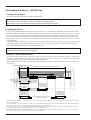
Reference -- Sheet Loading Position
The grit rollers on the PNC-950 are divided into three areas that can secure the sheet with the pinch rollers. The range of
movement is determined by the movable pinch rollers on the left and right (see "Reference"). Experiment with the range
of the left and right movable pinch rollers to determine usable area.
When loading a sheet, first place it atop the grit rollers and make sure that it is positioned where it can be secured by the
pinch rollers.
Range of movement for the left movable
pinch roller
Range of movement for the right movable pinch roller
Do not set the pinch roller here.
Grit roller 1
Move the left pinch
roller to align it with
the left edge of
the sheet
Sheets between
50 mm (1-15/16")
and 130 mm
(5-1/8") in width
Move the left pinch
roller to align it with
the left edge of
the sheet
Move the left
pinch roller to align
it with the left
edge of the sheet
Grit roller 2
Move the right
pinch roller to align
it with the right
edge of the sheet
Grit roller 3
Move the right
pinch roller to align
it with the right
edge of the sheet
Sheets between
125 mm (4-15/16")
and 370 mm (14-9/16") in width
Move the right
pinch roller to align
it with the right
edge of the sheet
Sheets between 365 mm (14-3/8") and
610 mm (24") in width
For a sheet between 50 mm (1-15/16") and 130 mm (5-1/8") in width, load the sheet -above grit roller (1), and move the left and right pinch rollers to
the 5/edges of the sheet.
For a sheet between 125 mm (4-15/16") and 370 mm (14-9/16") in width, load the left edge of the sheet above grit roller (1) and the right edge of the
sheet above grit roller (2), and move the left and right pinch rollers to the edges of the sheet.
For a sheet between 365 mm (14-3/8") and 610 mm (24") in width, load the left edge of the sheet above grit roller (1) and the right edge of the sheet
above grit roller (3), and move the left and right pinch rollers to the edges of the sheet.
The left pinch roller can only be moved above grit roller (1). The right pinch roller can be moved above grit rollers (1) to (3). Be sure to move the
pinch rollers to positions above the grit rollers when securing a sheet in place.
8
If You Are Using a Rolled Sheet
(1) Lower the sheet loading levers to raise the movable pinch rollers on the left and right, and move each of the pinch rollers all the way
to its respective side.
(2) Either cut the sheet to the required length, or set the sheet base included with the PNC-950 at the back of the unit, place a rolled
sheet on the sheet base. It is important to pull out the amount of sheet required for the intended design.
Pass the end of the sheet between the pinch rollers and the grit rollers so that it extends from the front of the unit.
OK
OK
Cut off the
length to be
used from the
rolled sheet
No good
Pull out the
length to be
used from the
rolled sheet
Sheet base
(3) Move the sheet from side to side and align the left edge of the sheet with the guide lines to the front and rear of the grit rollers.
Make sure at this time that both edges of the sheet lie over the grit rollers. (See “Reference -- Sheet Loading Position” on page 8.)
Movable pinch roller (left)
Pinch roll frame
Front of the
PNC-950
Back of the
PNC-950
Sheet
Sheet loading lever
Sheet
Guide line
Guide line
(4) Move the left and right movable pinch rollers to the two edges of the sheet. If a pinch roller does not move easily, it may help to
grasp the corresponding pinch roll frame (refer to illustration of step (3) ) at the back of the unit and move it together with the pinch
roller.
If you have placed a rolled sheet on the sheet base, make sure that the sheet is placed so that the left and right edges of the sheet both
come straight out through the PNC-950.
(5) After positioning the pinch rollers, raise the sheet loading levers at the rear of the unit to lower the pinch rollers and secure the sheet in
place. Do not put the pinch rollers on the end of the sheet when doing this.
(6) Press the SETUP key.
The tool carriage moves to the cutting origin point.
(7) Press the
key to feed out the length of sheet to be cut to the front of the PNC-950.
Press the
key to return the sheet back through to the rear of the unit.
The tool carriage returns to the origin you set in step (6).
(8) Check alignment during the test to make sure it is free of offset and alignment problems, diagonal feed problems, and pinch roller
handling problems. If there are any problems, the sheet was not loaded straight. Reload the sheet so that it is aligned straight.
9
- Ideally, the PNC-950 should be set up as shown in figure A or B below. If you are using a different setup configuration
(like in figures C, D, and E), then it will not be possible to feed the sheet correctly.
A: OK
B: OK
C: No good
D: No good
E: No good
- Be sure to use a sheet with a thickness (sheet and base paper) of 0.2 mm (about 0.008") or more.
- Do not use a sheet that has any of the following problems:
- Bent or torn edge
- Exposed and soiled adhesive
- Peeling, shrinking or exposed base paper
If You Are Using a Flat Sheet
(1) Lower the sheet loading levers to raise the movable pinch rollers on the left and right, and move each of the pinch rollers all the way
to its respective side.
(2) Pass the end of the sheet between the pinch rollers and the grit rollers so that it extends through the unit.
(3) Move the sheet from side to side and align the left edge of the sheet with the guide lines to the front and rear of the grit rollers.
Make sure at this time that both edges of the sheet lie over the grit rollers. (See “Reference -- Sheet Loading Position” on page 8.)
Movable pinch roller (left)
Pinch roll frame
Front of the
PNC-950
Sheet
Back of the
PNC-950
Sheet loading lever
Sheet
Guide line
Guide line
(4) Move the left and right movable pinch rollers to the two edges of the sheet. If a pinch roller does not move easily, it may help to
grasp the corresponding pinch roll frame (refer to illustration of step (3) ) at the back of the unit and move it together with the pinch
roller.
(5) After positioning the pinch rollers, raise the sheet loading levers at the rear of the unit to lower the pinch rollers and secure the sheet in
place. Do not put the pinch rollers on the end of the sheet when doing this.
(6) Press the SETUP key.
The tool carriage moves to the cutting origin point. (After scanning the sheet size, the cutting origin is set at the bottom left corner
of the sheet.) At this time, check the output sheet to make sure it is free of offset and alignment problems, diagonal feed problems,
and pinch roller handling problems. If there are any problems, the sheet was not loaded straight.Reload the sheet so that it is aligned
straight.
10
If You Are Using Another Kind of Sheet
If you are using any of the following kinds of sheets, neither of the methods described earlier will result in correct cutting.
- A scrap sheet or some other sheet with left and right edges that are not straight and may catch on the sheet guides
- A sheet with edge holes for sprocket feed that has no sheet layer (only base paper) along the hole area at the edges
Use the method described below to load the sheet.
* Set DIP switch SW-9 to OFF (roll sheet) and reset the power.
(1) Move the left and right pinch rollers all the way to their respective sides.
(2) Pass the end of the sheet between the pinch rollers and the grit rollers so that it extends from the front of the unit.
If you are using a rolled sheet, set the sheet base included with the PNC-950 at the back of the unit, place a rolled sheet on the sheet
base, and pull out slack from the roll.
(3) Move the sheet from side to side and align the left edge of the sheet with the guide lines to the front and rear of the grit rollers.
Make sure at this time that both edges of the sheet lie over the grit rollers.. (See “Reference -- Sheet Loading Position” on page 8.)
Move the left and right movable pinch rollers to the respective edges of the sheet. If a pinch roller does not move easily, it may help
to grasp the corresponding pinch roll frame (refer to illustration of step 4) at the back of the unit and move it together with the pinch
roller.
(4) If you are using a sheet scrap or some other sheet whose left and right edges are crooked, be sure to set the pinch rollers well inside
the edges so that the sheet does not come loose from the pinch rollers while cutting is in progress. If a sheet with sprocket-feed holes
is being used, make sure that the holes at the left and right edges are not placed atop the pinch rollers.
Movable pinch roller (left)
Pinch roll frame
Front of the
PNC-950
Back of the
PNC-950
Sheet
Sheet loading lever
Sheet
Guide line
(5) After positioning the pinch rollers, make sure that the left and right edges of the sheet lie parallel to the guide lines, then raise the sheet
loading levers at the rear of the unit to lower the pinch rollers and secure the sheet in place.
(6) Press the SETUP key.
The tool carriage moves to the cutting origin point.
If, after pressing the SETUP key, the PEN MODE LED and POWER/ERROR LED are both blinking at the same time, the following is the
cause.
Press the SETUP key (for about 1 sec.) to make the SETUP LED go out and move the tool carriage to the right. Then lower the sheet
loading levers.
- The location of the pinch rollers is incorrect.
Move the pinch rollers until they are positioned correctly over the grit rollers, and load a sheet. Press the SETUP key to proceed. (This
makes the SETUP LED light up.)
- If DIP switch SW-9 is set to ON ("piece"), then the length of the loaded sheet is too short.
Load a sheet with a length (vertical dimension) of 100 mm (3-15/16") or over, and press the SETUP key to proceed. (The SETUP LED
lights up.)
• Removing the Sheet
(2) Lower the sheet loading lever.
(1) Press the SETUP key.
Hold down for about 1 sec.
SETUP
→
Lower
The SETUP LED goes
out and the tool carriage
moves to the right edge
of the cutting area.
Sheet loading lever
(3) Remove the sheet.
11
• About the Cutting Area
584 mm (22-15/16")
Cutting area
About 1 mm (about 0.04")
24,998 mm
(984-1/8")
Movable Pinch Roller (Left)
About 15 mm (about 9/16")
* The arrows in the figure indicating
the X and Y directions indicate
respectively the positive directions
of the X axis and Y axis when the
Rotate function is off.
Cutting coordinate
origin (0,0)
Movable Pinch Roller (Right)
When use the sheet guide
Maximum cutting area: 558 mm (21-15/16") (horizontal direction) x 24,998 mm (984-1/8") (vertical direction)
4-5 Setting the Origin Point —
,
,
,
, ORIGIN SET Keys
The PNC-950 allows the origin point (0,0) to be set at any position in the cutting area.
When loading a rolled sheet set DIP switch SW-9 to OFF. Once the sheet is loaded and the SETUP key has been pressed,
the origin (0,0) is automatically set to a position near the left movable pinch roller on the left-hand side. When the
ROTATE key has been pressed to turn on the Rotate function and make the ROTATE LED light up, the origin is set to a
position near the movable pinch roller on the right-hand side.
When loading a flat sheet DIP switch SW-9 should be ON. Once the sheet is loaded and the SETUP key has been
pressed, the unit will scan and calculate the sheet's size, the origin (0,0) will be automatically set to the sheet's front left
edge.
If there is no need to move the origin initially set, then it is not necessary to make the origin point setting immediately
after loading a sheet.
You can also set the origin to an uncut area of a sheet in order to use the sheet with maximum effectiveness.
Procedure
* If a sheet has not yet been loaded, then before setting the origin point, refer to "Loading the Sheet" on page
7 to load the sheet correctly. Loading a sheet after the origin has been set (by pressing the SETUP key to
extinguish the SETUP LED) cancels the origin that has been set.
(1) Use the , , , and
keys to move the tool
carriage to the position on the sheet where the origin
point is to be set.
(2) Press the ORIGIN SET key.
ORIGIN SET
12
→
The SETUP LED flashes once
The origin point has been set
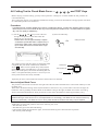
4-6 Cutting Test to Check Blade Force —
,
,
,
, and TEST Keys
Before carrying out actual cutting, you may wish to perform a "cutting test" to check whether the unit produces the
cutout satisfactorily.
This "cutting test" allows you to determine whether the settings you have for the blade force are appropriate. See below
for a detailed explanation of blade force.
Procedure
* If a sheet has not yet been loaded, then refer to "Loading the Sheet" on page 8 to load the sheet correctly.
Move the pen force control slider all the way to the left (minimum blade force). Increase blade force gradually, until cut quality is satisfactory.
(1) Use the , , , and
keys to move the tool
carriage to the position on the sheet where the
cutting test is to be executed.
* Note that an area of approximately 2 square
centimeters (a little less than a square inch) is
required to make a test cutout (given that the
tip of cutter after it has moved is at the origin
at lower-left).
The resulting cutouts will then appear as illustrated. When
completed, first peel off the round section (shaded as
shown
). When it can be peeled off by itself, without
disturbing the square, the blade force is set appropriately.
Next, peel off the square, and look at the backing that was
under it. The optimum blade pressure is correct if you can
clearly make out the lines left by the blade.
(2) Press the TEST key.
→
Cutting test starts
TEST
Peel off first
Then peel this off
Origin
Adjust the pen force control slider until results as shown above are obtained.
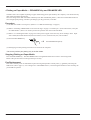
How to Adjust Blade Force
The pen force control slider is located on the right side of the unit. Move the blade force control slider sideways to alter
the blade force.
When slid to the farthest setting on the left, the blade force will be set to 30 g. As the slider is moved to the right, the
blade force will be gradually increased. When at the farthest setting on the right, the blade force will be set to 200 g,
which is the maximum blade force setting for the unit. At the center, the blade force will be approximately 120 g.
When making the blade force setting, it is important to take into consideration the hardness of the blade as well as the
thickness and type of the sheet to be cut, and adjust blade force accordingly. If the blade force is weak, the sheet may
not be cut satisfactorily. If the blade force is too strong, blade life will be shortened and cutting may be impaired.
Additionally, be aware that problems such as the following may occur.
• The sheet may be torn
• The blade may pierce the sheet and backing
• Cutter blade extends through the base paper, and normal advancing of the sheet becomes impossible
• The unit may suffer damage
13
4-7 Downloading Cutting Data
The unit will begin cutting when it receives cutting data sent from the computer.
• Software Settings
When cutting with commercially available application software, select PNC-950 as the setting for the output device. (If
the PNC-950 cannot be selected, choose any model in the PNC-900, PNC-1100, or PNC-1000A).
Select either the parallel (Centronics) or serial (RS-232C) interface. Choose the one that the host computer and the PNC950 are connected by.
• Pausing Cutting Operations — PAUSE Key, PAUSE LED, and SETUP Key
If you want to stop the PNC-950 momentarily while it is performing cutting, follow the procedure described below.
Procedure
(1) Press the PAUSE key.
PAUSE
(2)
To Resume Cutting
Press the PAUSE key.
→
The PAUSE LED lights up and cutting is paused
To Terminate Cutting
(2)-1 Halt transmission of cutting instructions from the
computer.
(2)-2 Hold down the SETUP key.
PAUSE
↓
The PAUSE LED goes out and
cutting resumes
SETUP
↓
The SETUP LED goes out, cutting instructions already sent from
the computer to the PNC-950 are deleted, the tool carriage moves
to the right, and cutting stops
* If you want to completely stop the operation of the PNC-950, turn off the power switch.
14
• Continuing Cutting
Cutting After Changing the Sheet
Follow the procedure described from "Loading the Sheet" on page 8 to "4-7 Downloading Cutting Data" on page 14.
* If the same type of sheet is used, then a cutting test is not necessary.
Continuing Cutting on the Same Sheet
Refer to "4-5 Setting the Origin Point" on page 12 to set the origin for the unused area on the sheet. Then send cutting
data from the computer to the PNC-950.
• Cutting a Thick Sheet
SW-8, one of the DIP switches located on the right side of the unit, is normally set to OFF (light).
It is recommended that SW-8 be set to ON (heavy) when cutting a thick or heavy sheet. Cutting speed slows down when
this is done, but the force used to move the sheet and the blade increases.
Remember that DIP switch settings must be made only when the power is turned OFF.
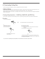
4-8 Applying the Completed Cutout
Once cutting has been completed, follow the procedure below for application instructions.
Procedure
• Make sure beforehand that the surface where the work is to be stuck is clean and free of all dust or oily
deposits.
• When applying the work to a transparent surface, such as a window, you can use a water-based pen (which
can be wiped off afterwards) to mark guidelines on the reverse side of the glass, to aid in getting the work
aligned properly.
(1)
For Flat Sheets
Refer to "Removing the Sheet" on page 11 to remove
the sheet from the PNC-950.
For Roll Sheets
Use the separate cutter or scissors to detach the work
area from the rolled sheet.
(2) Strip/Weed all unneeded portions from the completed
work.
(3) Stick application sheet over the completed work.
Press down firmly on the application sheet to
remove air bubbles. If you do not press firmly
enough the cut area will not stick to the surface.
(4) Carefully apply the work at the desired location, while
keeping it as straight as possible. Rub over the application tape to make sure the work is firmly stuck in place.
Then peel off the application sheet.
* You should have weed boarders or rectangles
drawn around work to facilitate weeding.
• If you discover after it is stuck in place that air bubbles were trapped under the work, use a needle to puncture them. Then you can smooth out the sheet out so that it sticks securely.
15
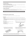
4-9 When Cutting Is Completed
(1) When cutting is finished, press down the sheet loading levers and remove the sheet. (See "Removing the Sheet" on
page 11.)
(2) If a blade was used, wipe the blade with a soft cloth to remove any pieces of the sheet that may be adhering to it. If
the pen was used then remove and recap the pen.
(3) Turn off the power.
If you do not intend to use the unit for an extended period of time, you should pull the plug for the power cord out of
the outlet.
* For routine cleaning, use a soft piece of cloth.
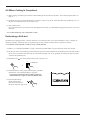
Performing a Self-test
The PNC-950 is equipped with a "self-test" function to conveniently allow you to check whether or not it is capable of
operating normally. If the PNC-950 is not performing correctly, follow the steps below to perform a self-test.
* A computer is not required in order to carry out the self-test.
(1) Refer to "4-3 Installing the Blade" on page 7 and install a blade holder (or pen) in the PNC-950's tool carriage.
(2) Set the pen force to the smallest possible value (the pen force slider should be at the furthest point to the left). If after
the first test you feel that the sheet was not cutout clean enough, you can try gradually increasing the pen force until
you have the optimum level.
(3) Hold down the
key on the panel while you turn the power on.
ON
POWER ON
+
OFF
(4) Load the sheet (or some paper), following the procedure
described in "4-4 Loading the Sheet" on page 8.
* If a pen and sheet have been loaded, press the
PEN MODE key to light up the PEN MODE LED.
(5) Press the SETUP key.
Demo cutting starts.
Operations is normal if
the figure shown at right is cut.
16
SETUP
5 SETTINGS FOR EACH FUNCTION
• Using a sheet effectively and cutting along the vertical dimension
(Rotate function) -- ROTATE Key and ROTATE LED
This function sets the origin point at the bottom right and rotates the text or graphics 90° (see pictures below). This
function is used when the intended design will not fit in the width (horizontal dimension) of the sheet, such as long
strings of text. If there is still unused material on the right side, rotation allows you to use this remaining material
effectively.
When the character string “Roland” is rotated by 90°, the X axis, Y axis, and origin change as follows:
0° Rotation - Rotate OFF
90° Rotation - Rotate ON
Roland
→
Roland
Origin
* The pairs of arrows indicate the positive directions along the X and Y axis.
Origin
Procedure
(1) Check that the SETUP LED
has gone out, and press the
ROTATE key.
ROTATE
→
The ROTATE LED lights up
* If the SETUP LED is illuminated, the ROTATE LED will not light up when the ROTATE key is pressed.
Press the SETUP key to extinguish the SETUP LED, then press the ROTATE key again.
(2) Press the SETUP key.
SETUP
→
The SETUP LED lights up
(3) Send cutting data from the computer.
Canceling the Rotate Function
After holding down the SETUP key for about one second to make the SETUP LED go out, press the
ROTATE key. The ROTATE LED is extinguished, and the origin returns to the point at bottom left.
The ROTATE function is also canceled when the power to the PNC-950 is turned off.
17
• Plotting on Paper Media — PEN MODE Key and PEN MODE LED
The PNC-950 is also capable of plotting on paper media using plotter pens made by this company. You should use only
thick water-based fiber-tipped pens.
Since the design of the PNC-950 differs inherently from that of dedicated plotters, it does not accommodate functions
such as high-speed plotting, automatic pen changes, pen dry protection, or the like.
Procedure
(1) Set DIP switch SW-9 to ON (piece). (Refer to "4-2 DIP Switch Settings" on page 6)
(2) Refer to "Installing a Blade Holder in the Tool Carriage" on page 7 to install a pen. (In the instructions, read "pen"
for "blade holder.") There is no need to perform an operation test when in the Pen Mode.
(3) Refer to "4-4 Loading the Sheet" on page 8 to load a piece of paper in the same way as for loading a sheet. Paper
with a width (horizontal dimension) between 50 mm (1-15/16") and 610 mm (24") can be loaded.
(4) Press the PEN MODE key.
PEN MODE
→
The PEN MODE LED lights up
(5) Plotting begins when plotting instructions are sent from the computer.
* Be sure to perform pen plotting only in the Pen Mode.
Stopping Plotting on Paper Media
Press the PEN MODE key. The PEN MODE LED is extinguished and the unit returns to the cutting mode.
Remove the pen from the tool carriage and cap it securely.
Pen Replacement
Pens will eventually wear out. Should the tip become rough and produce scratchy lines, try gradually increasing the
blade force (refer to page 13, "4-6 Cutting Test to Check Blade Force"). If increasing the blade force does not help, the
pen should be replaced.
18
6 ABOUT THE BLADE
If the blade becomes dull
When the blade starts to lose its sharpness, try gradually increasing the blade force (refer to page 13, "4-6 Cutting Test to
Check Blade Force").
Increasing the blade force temporarily allows the blade to perform better. However, once the blade is dull, it is time to
replace it. Since the blade is expendable, it must be replaced as often as necessary.
Average blade life
The life of a blade is determined mainly by the amount of cutting it performs.
The total cutting length actually obtained can vary considerably depending on the thickness, toughness, and type of
adhesive layer that the sheet has. Set an appropriate blade force, one that is well matched to the type of sheet and
hardness of the blade, and the life of the blade will be extended. Excessive blade forces can cause the blade to wear out
quickly. Care should be taken.
19
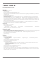
7 WHAT TO DO IF...
If the PNC-950 doesn't run...
PNC-950
• Is the PNC-950 power on?
Turn on the power.
• Is the unit in SETUP status (the SETUP LED is lit)?
If the SETUP LED is not illuminated, make sure the sheet is loaded correctly and press the SETUP key to illuminate
the SETUP LED.
• Is the PAUSE LED illuminated?
If the PAUSE key has been pressed and the PAUSE LED is lit up, the unit has been paused (see "Pausing Cutting
Operations" on page 14).
If you want to resume cutting, press the PAUSE key again. The PAUSE LED is extinguished, and cutting resumes.
If you want to terminate cutting, first stop the transmission of cutting instructions from the computer to the PNC-950.
Then press the SETUP key. This deletes the cutting instructions that have already been sent from the computer to the
PNC-950, and cutting is stopped.
• If connected via the serial port, do the communication parameters for the PNC-950 match those of the computer?
Set the DIP switches correctly (see "4-2 DIP Switch Settings" on page 6.)
Computer
• Is the computer set up correctly?
Check the following items:
• DIP switches
• Memory switches
• Interface board
Read the computer user’s manual and set it up correctly.
• Communication parameters
• Other settings
Connection cable
• Are the computer and the PNC-950 linked with the right cable?
The type of cable you need is determined by your computer and the software you are using. Even if the computer is the
same, running different software may require a different cable. Use the cable specified in your software.
• Is the cable making a secure connection?
Connect securely.
Software
• Is the OS set up correctly?
Check the following items:
• Output port selection
• Output device selection
• Output port open
• Communication parameters
• Other settings
Check the OS user’s manual and set it up correctly.
• Are the application software settings correct?
Check the following items:
• Output device specifications (select a device name that matches the instruction system. If the wrong device is
selected an incorrect instruction may be output, resulting in an error).
• Communication parameters
• Other settings
Check the software user’s manual and set it up correctly.
• Are the settings for the driver software correct?
If you are using driver software for output on the PNC-950, then make the settings for the correct driver in the computer. Select the PNC-950 as the output device. If the PNC-950 is not available as a selection, you may select either
the PNC-900, PNC-1100, or PNC-1000A.
20
The POWER/ERROR LED is blinking
If there is an error in the data downloaded to the PNC-950 from the computer, the PNC-950 generates an error (the POWER/
ERROR LED begins to blink), and cutting cannot be carried out. The error can be canceled by switching off the power.
After turning off the power, check the following.
• If you are using application software, has the correct output device been selected?
Select "PNC-950" as the output device. If this selection is not available, select any model in the PNC-900, PNC-1100
or PNC-1000A).
• If you are using a program that you have created yourself, have correct commands been sent?
The PNC-950 is equipped with the CAMM-GL III instruction system. For details, refer to "8 List of CAMM-GL III
Instructions" on page 22.
• Do the DIP switch settings match the settings made for the application software?
Refer to "4-2 DIP Switch Settings" on page 6 to make the correct DIP switch settings.
• Does the connecting cable match the settings for the application software and the computer?
Refer to the operation manuals for your application software and computer to select and connect the appropriate cable.
The PEN MODE LED and POWER/ERROR LED blink simultaneously
• The position of the pinch rollers when the sheet is loaded is not correct (i.e., there are no grit rollers under the pinch
rollers).
These two LEDs also blink simultaneously if DIP switch SW-9 is set to OFF ("piece") and a flat sheet with a vertical
length of 100 mm (3-15/16") or less has been loaded.
You can cancel the error by pressing the SETUP key.
See "4-4 Loading the Sheet" on page 8 to load the sheet correctly.
The sheet is not cut properly
• Are the blade and blade holder installed correctly and securely?
Install these so that there is no looseness (see "4-3 Installing the blade" on page 7).
• Is the blade chipped?
If it is, replace it with a new one (see "4-3 Installing the blade" on page 7).
• Check if there are any dirty deposits on the blade.
If dirty, remove and clean the blade.
• Is the PEN MODE LED lit up?
If the PEN MODE key has been pressed and the PEN MODE LED has lit up, it means that the PNC-950 has been set
up for plotting on paper, which is not suitable for cutting.
Press the PEN MODE key to make the PEN MODE LED go out before trying to perform cutting (refer to page 18,
"Plotting on Paper Media").
• Make sure you are using an appropriate blade force setting.
Perform a "cutting test," then adjust the blade force slider as necessary to obtain the optimum blade force (refer to page
13, "4-6 Cut Test to Check Blade Force").
• When cutting a thick sheet, set DIP switch SW-8 to ON (heavy). (See "4-2 DIP Switch Settings" on page 6 and
"Cutting a Thick Sheet" on page 15.)
The sheet slips away from the pinch rollers during the cutting process
• Are the sheet loading levers on both the left and right sides raised?
If a sheet loading lever has not been raised, then the sheet has not been secured in place. Make sure that the pinch
rollers on the left and right sides are within the boundaries of the sheet, and raise the sheet loading levers. (Refer to "44 Loading a Sheet" on page 8.)
• Make sure the sheet is parallel with the grit roller.
If the front edge of the sheet you are working with is at an angle, cut off the odd-shaped part to make it straight, then
align it so that it is parallel with the grit roller.
• If the sheet is to be advanced over a long distance, moving the movable pinch roller inward slightly can help prevent
the sheet from becoming dislodged. Also, after loading the sheet, it is recommended that you carry out an alignment
test by using the
key to advance the sheet by the amount that will be used for cutting, and make sure that the sheet
travels correctly through the machine.
• If a roll sheet is used, carry out cutting after first pulling out the amount of sheet that is to be used. The sheet may
easily slip if cutting is performed while pulling a sheet that is still rolled up into the PNC-950.
• Make sure that the left and right edges of the sheet do not touch the inner surfaces of the PNC-950 during cutting.
Such contact may not only damage the sheet, but could also make normal sheet advancing impossible and cause the
sheet to slip.
21
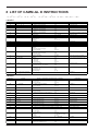
8 LIST OF CAMM-GL III INSTRUCTIONS
*1: -(226-1) — +(226-1)
*2: 0 — +(226-1)
*3: -(226-1)° — +(226-1)°
*4: 21(16) — 3A(16), 3C(16) — 7E(16)
• mode1
Instruction
H
D
Format
H
D x1, y1..., xn, yn
M
M x1, y1...xn,yn
I
I x1, y1..., xn, yn
R
R x, y
L
B
X
Lp
Bl
X p,q,r
P
S
Q
N
C
P c1c2...cn
Sn
Qn
Nn
C x, y, r, Ø1, Ø2(,Ød)
E
E r, Ø1, Ø2(,Ød)
A
A x, y
G
G r,Ø1, Ø2(,Ød)
K
K n, l1, l2
T
T n, x, y, d, t
^
[mode 2 instruction] [parameter]....,
[parameter] [terminator]
Meaning of Parameter [Parameter Range (Default)]
None
xn: Absolute X-axis coordinate
[*1]
yn: Absolute Y-axis coordinate
[*1]
xn: Absolute X-axis coordinate
[*1]
yn: Absolute Y-axis coordinate
[*1]
xn: Relative X-axis coordinate
[*1]
yn: Relative Y-axis coordinate
[*1]
xn: Relative X-axis coordinate
[*1]
yn: Relative Y-axis coordinate
[*1]
p: Line pattern
[-5 — +5 (0)]
l: Pitch length
[*2 1.5% of (P2-P1) ]
p: Coordinate axis
[0, 1]
q: Tick interval
[*1]
r: Number
[1—32767]
cn: Character
n: Character size
[0—127 (61)]
n: Rotation angle (90°as a unit)
[n =0 — 3 (0)]
n: Number of special symbol
[1—15]
x, y: Center coordinates
[*1]
r: Radius
[*1]
Ø1•Ø2: Start angle • End angle
[*1]
Ød: Chord tolerance
[*1 (5°)]
r: Radius
[*1]
Ø1•Ø2: Start angle • End angle
[*1]
Ød: Chord tolerance
[*1 (5°)]
x: Center x coordinate
[*1 (0)]
y: Center y coordinate
[*1 (0)]
r: Radius
[*1]
Ø1: Start angle
[*1]
Ø2: End angle
[*1]
d: Chord tolerance
[*1 (5°)]
n: Division line angle
[*1]
l1: Division line end point distance
[*1]
l2: Division line start point distance
[*1]
n: Hatching pattern
[0—3]
[*1]
x, y: Rectangle size
d: Hatching spacing
[*1]
t: Hatching angle
[1—4]
Explanation
Move to User Origin
Cut Absolute Line
Tool-up to Absolute Coordinate Point
Cut Relative Line
Tool-up Move to Relative Coordinate
Point
Specify Line Type
Specify Broke Line Pitch
Plot Coordinate System
Plot Character
Set Character Size
Specify Character Rotate Angle
Plot Special Symbol
Cut Arc
Cut Arc from Tool Position
Specify G & K Center Coordinate
Cut Arc Around A-Instruction Center
Plot Division Line
Plot and Hatch Rectangle
Call mode 2
• mode2
Instruction
AA
AR
AR x, y,Øc(,Ød);
CA
CA n;
CA;
CI r(,Ød);
CI
CP
DT
EA
ER
EW
CP nx,ny;
CP;
CS n;
CS;
DF;
DI run, rise;
DI;
DR run, rise;
DR;
DT t;
EA x, y;
ER x, y;
EW r, Ø1, Øc(,Ød);
FT
FT n(,d(,Ø));
CS
DF
DI
DR
IM
IN
IP
22
Format
AA x,y,Øc(,Ød);
FT;
IM e;
IM;
IN;
IP P1x, P1y, P2x, P2y;
IP;
Meaning of Parameter [Parameter Range (Default)]
x, y: Absolute center coordinates
[*1]
Øc:Center angle
[*1]
Ød: Chord tolerance
[*1 (5°)]
x, y: Relative center coordinates
[*1]
Øc: Center angle
[*1]
Ød: Chord tolerance
[*1 (5°)]
n: Character set No.
[0 — 4, 6 — 9, 30 — 39]
r: Radius
Ød: Chord tolerance
nx: Number of characters in X-axis direction
ny: Number of characters in Y-axis direction
n: Character set number
[*1]
[*3 (5°)]
[*1]
[*1]
Arc Relative
Alternate Character set
Circle
Character Plot
Standard Character Set
None
run: X-axis direction vector
[*1 (1)]
rise: Y-axis direction vector
[*1 (0)]
run: X-axis direction vector
[*1 (1)]
rise: Y-axis direction vector
[*1 (0)]
t: Label terminator
[ [ETX] ]
x, y: Absolute XY coordinates of opposite angle of rectangle [*1]
x, y: Relative XY coordinates of opposite angle of rectangle [*1]
r: Radius
[*1]
Ø1: Start angle
[*3]
Øc: Center angle
[*3]
Ød: Chord tolerance
[*3 (5°)]
n: Pattern
[1 — 5 (1)]
d: Spacing
[*2 ((P2x-P1x) x 0.01)]
Ø: Angle
[*3 (0°)]
e: Error mask value
[0 — 255 (223)]
None
P1x, P1y: XY coordinates of P1
P2x, P2y: XY coordinates of P2
Explanation
Arc Absolute
[*1]
[*1]
Default
Absolute Direction
Relative Direction
Define Label Terminator
Edge Rectangle Absolute
Edge Rectangle Relative
Edge Wedge
Fill Type
Input Mask
Initialize
Input P1 & P2
Instruction
IW
OA
OC
OE
OF
Format
IW LLx, LLy, URx, URy;
IW;
LB c1c2c3...cn
[label terminator]
LT n(,l);
LT;
OA;
OC;
OE;
OF;
OH
OI
OH;
OI;
OO
OO;
OP
OS
OW
PA
WG
OP;
OS;
OW;
PA x1, y1(...,xn, yn);
PA;
PD x1, y1(...,xn, yn);
PD;
PR 1, y1(... xn, yn);
PR;
PT d;
PT;
PU x1, y1(...,xn, yn);
PU;
RA x, y;
RR x, y;
SA;
SC Xmin, Xmax, Ymin, Ymax;
SC;
SI w, h;
SI;
SL tanØ;
SL;
SM s;
SM;
SR w, h;
SR;
SS;
TL lp(,lm);
TL;
UC (c,) x, y,(c,)
,...., xn, yn;
UC;
VS v;
VS;
WG r, Ø1, Øc(,Ød);
XT
YT
XT;
YT;
LB
LT
PD
PR
PT
PU
RA
RR
SA
SC
SI
SL
SM
SR
SS
TL
UC
VS
Meaning of Parameter [Parameter Range (Default)]
LLx, LLy : lower left coordinates of window
URx,URy : Upper right coordinates of window
c: Character string
Explanation
Input Window
Label
n: Pattern number
[0 — 6 (solid line)]
l: 1 pitch length
[*2 (1.5% of (P2-P1))]
None
None
None
None
When the PNC-950 receives an OF instruction from the computer,
"40,40 [TERM]" is output.
None
None
When the PNC-950 receives an OI instruction from the computer,
"950 [TERM]" is output.
None
When the PNC-950 receives an OO instruction from the computer,
"0,0,0,0,1,0,0,0 [TERM]" is output. The "1" in this output indicates that
circle and arc commands have been loaded
None
None
None
xn, yn: Absolute XY coordinates
[*1]
Line Type
xn, yn: XY coordinates
[*1]
Tool Down
xn, yn: Relative XY coordinates
[*1]
Cut Relative
d: Pen thickness (mm)
[0—5 (0.3)]
Pen Thickness
xn, yn: XY coordinates
[*1]
Tool Up
x, y: Absolute XY coordinates of opposite angle of rectangle [*1]
x, y: Relative XY coordinates of opposite angle of rectangle [*1]
None
Xmin, Ymin: User XY coordinates of P1
[*1]
Xmax, Ymax: User XY coordinates of P2
[*1]
w: Character width (cm.)
[-128 — +127.99999 (3.8)]
[-128 — +127.99999 (5)]
h: Character height (cm.)
tanØ: Character slant
[*1 (0)]
Output Actual Point
Output Commanded Position
Output Error
Output Factor
Output Hard-Clip Limits
Output Identification
Output Option Parameter
Output P1 & P2
Output Status
Output Window
Cut Absolute
Shade Rectangle Absolute
Shade Rectangle Relative
Select Alternate Set
Scaling
Absolute Character Size
Character Slant
s: Character or symbol
[*4 (Default:
Symbol Mode
Clears symbol mode)]
w: Character width (%)
[*1 (3.8 )]
Relative Character Size
h: Character height (%)
[*1 (5 )]
None
Select Standard Set
lp: Tick length in positive direction
[*2 (0.5%)]
Thick Length
[*2 (0.5%)]
lm: Tick length in negative direction
c: Tool control value
[-(67108863) — -99, +99 — +(67108863)] User Defined Character
xn: Units of movement in X-axis direction
[-99< xn<+99]
yn: Units of movement in Y-axis direction
[-99< yn<+99]
v: Tool speed (cm/sec.)
[1 — 40 ]
Velocity Select
r : Radius
Ø1 : Start angle
Øc : Center angle
Ød : Chord tolerance
None
None
[*1]
[*3]
[*3]
[*3 (5°)]
Shade Wedge
X-Tick
Y-Tick
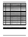
• Instructions in mode1 and mode2
Instruction
!NR
!PG
!ST
Format
!NR [terminator]
!PG n [terminator]
!ST n [terminator]
Meaning of Parameter [Parameter Range (Default)]
None
n:
n:
[-24998 — +24998 mm]
[0, 1]
Explanation
Not Ready
Page Feed
Select Tool
23
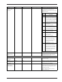
9 LIST OF DEVICE CONTROL INSTRUCTIONS
Device control instructions are used to determine the communication sequence between the PNC-950 and computer
through RS-232C interface and update the computer the current PNC-950 state. Among them, some device control
instructions set the output specifications of CAMM-GL III instructions.
Each device control instruction is organized with three letters: [ESC] , "." and one uppercase letter. Device control
instructions are of two types: one with parameters and the other without parameters.
Parameters can be omitted. A semicolon ";" is used as a delimiter to separate parameters if they are input in succession.
A ";" without parameters means that parameters were omitted.
If parameters are omitted, the default value is set. For a device control instruction with parameters, a terminator needs to
be input in order to signify the end of instructions. A colon ":" is used as the terminator which cannot be omitted.
Instruction
Format
Parameter
Range
([ ] is default)
Explanation
Handshake Instructions
ESC .B
[ESC].B
None
Outputs the current remaining buffer capacity to the
Output Remaining
computer.
Buffer Capacity
ESC .M
Set Handshake
[ESC].M<P1>;<P2>;
P1: Delay time
<P3>;<P4>;<P5>;<P6>: P2: Output trigger character
0—32767 (msec) [0 (msec)]
Sets handshake output specifications.
[0 (Sets nothing)]
Output
P3: Echo terminator
[0 (Sets nothing)]
Specifications (1)
P4: Output terminator
[13 ([CR])]
Note: When you specify some values to <P4> and
P5: Output terminator
[0 (Sets nothing)]
<P5>, always set 0 to <P6>. When you specify
P6: Output initiator
[0 (Sets nothing)]
some value to <P6>, always set 0 to <P5>.
[ESC].N<P1>;<P2>;
P1: Intercharacter delay
0—32767 (msec) [0 (msec)]
Sets an intercharacter delay, and also an Xoff
<P3>; ••••• ;<P11>:
P2-P11
[All 0 (Sets nothing)]
character for performing the Xon/Xoff handshake.
ESC .N
Set Handshake
Output
: Xoff character (for Xon/Xoff)
Specifications (2)
Immediate response character
(for ENQ/ACK)
ESC .H
Sets ENQ/ACK
[ESC].H<P1>;<P2>;
<P3>; •••••••• ;<P12>:
Handshake Mode1
P1: The number of bytes for
data block
P2: ENQ character
0—15358 (byte) [80 (byte)]
compares the value set by <P1> and the remaining
[All 0 (Sets nothing)]
buffer capacity, and returns the ACK character to
P3-P12
the host computer when the remaining buffer
: ACK character (only when
capacity is larger. The [ESC].H with no parameter
<P2> is set)
ESC .I
Set Xon/Xoff
[ESC].I<P1>;<P2>;
P1: Limit of the remaining
<P3> ; •••••••• ;<P12>:
buffer capacity (for Xon/Xoff)
When receiving the ENQ character set by <P2>,
[0 (Sets nothing)]
performs a dummy handshake.
0—15358 (byte) [80 (byte)]
Used for performing the Xon/Xoff handshake and
the ENQ/ACK handshake mode 2.
Handshake and
The number of data block bytes
The [ESC].I instruction with no parameter performs
ENQ/ACK
(for ENQ/ACK (mode2))
a dummy handshake. In a dummy handshake,
Handshake Mode2
P2: ENQ character
[0 (Sets nothing)]
always returns the ACK character to the host
(for ENQ/ACK (mode2))
computer, regardless of the remaining buffer
0 (for Xon/Xoff)
capacity, when receiving the ENQ character.
P3-P12
[All 0 (Sets nothing)]
: Xon character(for Xon/Xoff)
ACK character
(for ENQ/ACK (mode2))
ESC .@
[ESC].@ P1;P2:
Controls DTR
P1: Ignored
P2: DTR signal control
Controls the DTR signal (No. 20 pin of RS-232C).
0—255
[1]
An even number parameter (e.g. 0) always sets the
DTR signal to High without performing the
hardware handshake. An odd number parameter
(e.g. 1) performs the hardware handshake and
controls the DTR signal according to the remaining
buffer capacity.
Status Instructions
ESC .O
Outputs the Status
of Buffer, Pause
24
[ESC].O
None
Outputs the status codes of PNC-950 shown in
the table below.
Code
Meaning
0
Data remaining in buffer.
8
Buffer empty.
16
Data remaining in buffer. PNC-950
being paused (Pause On being displayed).
24
Buffer empty. PNC-950 being
paused (Pause On being displayed).
Instruction
ESC .E
Format
[ESC].E
Parameter
None
Range
([ ] is default)
Explanation
Outputs an error code related to RS-232C interface
Output RS-232C
(see the table below), and clears the error
Error Code
simultaneously. At the same time, the error being
displayed is canceled.
Error
Possible cause
code
0
10
and action
No I/O errors
Cause: after execution of an output
command, other output instructions are
sent before the output was not completed.
Action: let the computer to read the PNC950 output by the output instruction
and then send another output instruction.
11
Cause: an error occurs in a device
control instruction.
Action: correct your program.
12
Cause: incorrect parameter are set to a
device control instruction (the default
value is set to the erroneous parameter)
Action: correct your program.
13
Cause: parameters are overflowing.
Action: correct your program.
14
Cause: the number of the parameters set
is more than specified or a colon ':' was
not used to terminate.
Action: correct your program.
15
Cause: framing error, parity error or
over-run error at the time of data receipt.
Action: match the communication
protocols of both computer and PNC950 (baud rate, data bit length,
stop bit length).
16
Cause: the I/O buffer overflows.
Action: This error does not occur when
hardware handshake is performed, but
may occur when software handshake is
performed. If this error occurs, check
the remaining buffer capacity of the
PNC-950 and send less data than the
remaining buffer capacity.
ESC .L
[ESC].L
None
PNC-950 outputs the size of the I/O buffer to
Output I/O buffer
the computer when receiving this instruction.
size
It usuallyoutputs 1024 (bytes).
Abort Instructions
ESC .J
[ESC].J
None
Abort Device Control
Aborts both the currently executed device control
instruction and output.
Instruction
ESC .K
[ESC].K
None
Abort CAMM-GLIII
in operation, aborts other incoming CAMM-GL III
Instruction
ESC .R
Continues to execute the CAMM-GL III instruction
instructions and clears the data buffer.
[ESC].R
None
Initializes all settings established by the device
Initialize Device
control instructions. Execution of [ESC].R brings
Control Instruction
the same states as the following device control
instructions are executed.
[ESC].J, [ESC].M:, [ESC].N:, [ESC].H:,
[ESC].I: and [ESC].@:
25
10 CHARACTER SETS
Automatic backspace
26
11 LIST OF OPTIONS
Option name
Spare blade (for
Product number
Description
ZEC-U1005
Cemented carbide blade (5 pcs/set)
ZEC-U5025
Cemented carbide blade (5 pcs/set)
Blade holder
XD-CH1
Blade holder (1 piece)
Ajustable Blade Holder
XD-CH2
Blade holder (1 piece)
Water-based
fiber-tipped pens
XD-4SPA-WNG
0.3 mm 4 black
XD-4SPB-WNG
0.3 mm one each-black, red, blue, and green
XD-4SPC-WNG
0.3 mm one each-orange, pink, blown, and violet
XD-4SPA-WWG
0.6 mm 4 black
XD-4SPB-WWG
0.6 mm one each-black, red, blue, and green
XD-4SPC-WWG
0.6 mm one each-orange, pink, blown, and violet
XD-4SPA-WBG
2.0 mm 4 black
XD-4SPB-WBG
2.0 mm one each-black, red, blue, and green
XD-4SPC-WBG
2.0 mm one each-orange, pink, blown, and violet
XD-4SPD-WBG
2.0 mm 4 red
XD-4SPE-WBG
2.0 mm 4 blue
XD-4SPF-WBG
2.0 mm 4 green
XD-4SPG-WBG
2.0 mm 4 orange
XD-4SPH-WBG
2.0 mm 4 pink
XD-4SPI-WBG
2.0 mm 4 blown
XD-4SPJ-WBG
2.0 mm 4 violet
standard vinyl sheet)
Spare blade (for thick,
fluorescent vinyl sheet)
Thick Water-based
fiber-tipped pens
32 color plotter pens
(0.3 mm)
XR-2P1A-WN ~ XR-2P8A-WN
XR-2P1B-WN ~ XR-2P8B-WN
Fiber tip pen (0.3 mm) x 2 in 1 color
XR-2P1C-WN ~ XR-2P8C-WN
XR-2P1D-WN ~ XR-2P8D-WN
32 color plotter pens
(0.6 mm)
XR-2P1A-WW ~ XR-2P8A-WW
XR-2P1B-WW ~ XR-2P8B-WW
Fiber tip pen (0.6 mm) x 2 in 1 color
XR-2P1C-WW ~ XR-2P8C-WW
XR-2P1D-WW ~ XR-2P8D-WW
Special stand for the PNC-950
PNS-95
Special stand for the PNC-950 -- 1 set
Sheet base (for roll sheets)
RSB-30
Sheet base (1 piece)
27
12 SPECIFICATIONS OF PNC-950
PNC-950
Mechanism
Media-movement method
Maximum cutting area
Width: 584 mm (22-15/16")
Length: 24,998 mm (984-1/8")
Acceptable sheet widths
50 mm—610 mm (1-15/16"—24")
Acceptable paper widths
50 mm—610 mm (1-15/16"—24")
Acceptable paper types
High-quality paper
Tools
Cutters: carbide
Pens: Water-based fiber-tipped pens, Thick water-based fiber-tipped pens (options) and
32 color plotter pens (options)
Cutting speed
10 mm/sec—400 mm/sec
(When DIP switch SW-8 is at ON: 10 mm/sec - 100 mm/sec)
Blade force
30 gf—200 gf
Mechanical resolution
0.05 mm/step (Micro-step: 0.003125 mm/step)
Software resolution
0.025 mm/step
Distance accuracy
Error of less than +/- 0.2% of distance travelled, or 0.1mm, whichever is grater
Repetition accuracy
0.1 mm or less (Excluding stretching/contraction of the sheet, and provided that sheet length
is under 1600 mm (62-15/16"))
Interface
Parallel (Centronics compatible), Serial (RS-232C)
Buffer size
2 Kbytes (expandable up to 1 Mbyte)
Instruction system
CAMM-GLIII (mode1and mode2)
Switches
Power switch, pen force slider, DIP switches
Control switches
SETUP, PAUSE, PEN MODE, ROTATE, TEST, ORIGIN SET,
LED
POWER/ERROR LED, SETUP LED, PAUSE LED, PEN MODE LED, ROTATE LED
Power consumption
0.7 A /117 V, 0.4 A / 220 - 230 V, 0.4 A / 240 V
Acoustic noise level
[Cutting mode]
When DIP switch SW-8 is at OFF: less than 68 dB (A)
When DIP switch SW-8 is at ON: less than 69 dB (A)
[Standby mode]
less than 45 dB (A)
(according to ISO 7779)
Dimensions
805 mm (W) x 289 mm (D) x 217 mm (H)
(31-3/4" (W) x 11-7/16" (D) x 8-9/16" (H))
Weight
14 kg (30.9 lb.)
Operating temperature
5—40°C (41—104°F)
Operating humidity
35%—80% (non-condensing)
28
,
,
,
• Interface Specifications
[Parallel]
Standard
In compliance with the specifications of Centronics
Input signals
STROBE (1 BIT), DATA (8 BIT)
Output signals
BUSY (1 BIT), ACK (1 BIT)
Level of input/output signals
TTL level
Transmission method
Asynchronous
[Serial]
Standard
RS-232C specifications
Transmission method
Asynchronous, duplex data transmission
Transmission speed
4800, 9600 (Selected using DIP switches.)
Parity check
Odd, Even, or None (Selected using DIP switches.)
Data bits
7 or 8 bits (Selected using DIP switches.)
Stop bits
1 or 2 bits (Selected using DIP switches.)
Parallel Connector (in compliance with
specifications of Centronics)
Signal Terminal Signal
number number number
NC
36
18
HIGH**
HIGH*
35
17
GND
NC
34
16
GND
GND
33
15
NC
HIGH*
32
14
NC
NC
31
13
HIGH*
30
12
GND
29
11
BUSY
28
10
ACK
27
9
D7
26
8
D6
25
7
D5
24
6
D4
23
5
D3
22
4
D2
21
3
D1
20
2
D0
19
1
STROBE
GND
Serial Connector (RS-232C)
Pin Connection
1
18
19
36
+5 V
3.3K ‰
*=
+5 V
Signal Terminal
number number
Signal
number
NC
25
13
NC
NC
24
12
NC
NC
23
11
NC
NC
22
10
NC
NC
21
9
NC
DTR
20
8
NC
NC
19
7
SG
NC
18
6
DSR
NC
17
5
CTS
NC
16
4
RTS
NC
15
3
RXD
NC
14
2
TXD
1
FG
Pin connection
13
1
25
14
100 ‰
** =
29
C3070395BE V5-1