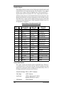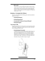
1
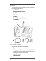
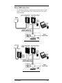
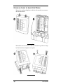
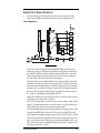
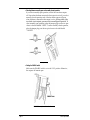
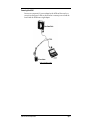
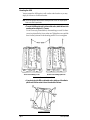
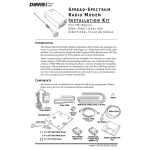
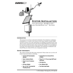
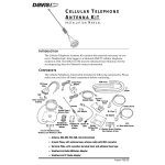
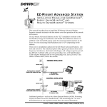
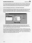
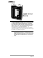
ALARM OUTPUT
MODULE
The Alarm Output Module (AOM) enables you to use weather station alarms
or commands from your computer to automatically start or stop external
devices such as indicator lights, audio alarms, sprinkler controllers, relays, or
other low-voltage AC or DC loads. The AOM works with the GroWeather™,
Energy EnviroMonitor™, or the Heath EnviroMonitor™. The
GroWeatherLink® and Energy WeatherLink® also allow you to control two
alarm outputs manually (by turning them on or off from the software), though
the software is not required for basic operation.
CAUTION: WHILE WE HAVE MADE EVERY EFFORT TO INSURE THAT THE ALARM OUTPUT MODULE
WILL WORK RELIABLY, YOU SHOULDNOT USE IT IN SITUATIONS INVOLVING POTENTIAL
PROPERTY LOSS OR HAZARDS TO HEALTH OR SAFETY OF PEOPLE OR LIVESTOCK. DAVIS
INSTRUMENTS CANNOT BE HELD LIABLE FOR ANY FAILURE OF THE ALARM OUTPUT
MODULE.
Product #7736
C OMPONENTS
The AOM includes the following components. Please make sure you have all
listed components before continuing.
✦ Alarm Output Module
✦ Alarm Output Module Cable, 2-foot (0.6 m)
✦ Power Y-Cable
✦ AC-Power Adapter
✦ Two Cable Ties
✦ Three #6 x 1” (25 mm long) Self-Threading Screws
✦ Four Adhesive Pads
T OOL
AND
M ATERIALS N EEDED
You will need some of the following tools and materials.
✦ Relays
You may need to obtain your own relays in order to switch equipment at
voltages higher than 28 volts or power levels above 10 Watts or to provide time delays or other logic functions. Application notes discussing
this further are available from Davis Instruments.
✦ Medium Phillips Screwdriver
✦ Small Slotted Screwdriver
Page 2
Alarm Output Module
T YPICAL AOM I NSTALLATIONS
The AOM may be connected to either the sensor interface module or to the
Interface Cable Adapter Module. The two illustrations below show typical
AOM installations.
AOM CONNECTED TO SENSOR INTERFACE MODULE
AOM CONNECTED TO INTERFACE CABLE ADAPTER MODULE
Typical AOM Installations
Page 3
O PENING
AND
C LOSING
THE
A LARM O UTPUT M ODULE
Remove the cover by pushing down on the tabs at the top until you can remove
the tabs from the slots.
REMOVING THE COVER
Reattach the cover as shown below. Make sure the tabs on top of the cover snap
back into their slots, locking the cover in place
REATTACHING THE COVER
Page 4
Alarm Output Module
A LARM O UTPUT M ODULE O PERATION
The section below provides technical information on the operation of the
Alarm Output Module. Installation instructions appear separately below.
Circuit Operation
AOM CIRCUIT DIAGRAM
The Console sends to the Sensor Interface Module (SIM) a serial data word
containing one bit for each alarm signal and user- and system-controlled output. From the SIM (or the Interface Cable Adapter Module) this is sent to the
Alarm Output Module. The data are sent twice, once in true form and once
inverted, and are shifted into the AOM’s Input Register.
When the Verify circuit confirms that the correct number of bits has been sent
and that the two data sets match correctly, it generates a LOAD pulse to transfer the data into the Output Register. All 16 bits of this register are available at
terminal strip J3 for selection as outputs. Four of the 16 are jumper-selected by
the user to drive the photo-coupled outputs and appear as contact closures A,
B, C, and D (closure indicated by lighted red LEDs).
Setting the ENABLE switch off causes all contacts to open (the LEDs continue
to indicate the state of the selected alarms).
The LOAD command pulse is sent back to the Console, where “quality of data
transfer” is determined and sent to the Link software. LOAD also flashes the
yellow indicator to show that a good transfer has occurred.
Two Set/Reset (RS) Flip-flops can be used to latch the four outputs. Latch 1 is SET
by output A and RESET by B. Latch 2 is SET by output C and RESET by D. The
Latch contents are available as output contact closures L1 and L2 (set ON = closed).
The OK circuits check that a good transfer has occurred within the past 10 seconds or so, that the power voltage is good, and that the ENABLE switch is on.
This validity check result is indicated by the green LED and is available as the
OK output contact (OK = closed).
Alarm Output Module Operation
Page 5
Available Outputs
The AOM provides four output contacts which may be selected from the conditions listed below. Each output (except time, daily ET, and the “User” outputs)
remains active as longs as the alarm condition exists. The time and daily ET
outputs remain active for one minute. The “User” outputs must be activated
and deactivated by the user via the WeatherLink Software for that station. Also
shown in the table below are the pin assignments for each of the three consoles.
The “Radio Power” output is used to control switching of power to radio when
in the power-conserving mode (see “AOM Connections for Radio Power-Conserving Options” on page 12).
ALARM SIGNAL PIN ASSIGNMENTS (J3)
ALARM
OUTPUT
J3
PIN
GROWEATHER
CONSOLE
ENERGY EM
CONSOLE
HEALTH EM
CONSOLE
16
Time
Time
Air Temp-Low
15
Daily ET
Temp-Hum Index
Air Temp-High
14
Dew Point
Dew Point
Inside Temp-Low
13
Radio Power
Radio Power
Inside Temp-High
12
Hum-Low
Air Temp-Low
Outside Hum-Low
11
Hum-High
Air Temp-High
Outside Hum-High
10
Air Temp-Low
Hum-Low
Inside Hum-Low
9
Air Temp-High
Hum-High
Inside Hum-High
8
Soil Temp-Low
Wind Chill
UV Dose
7
Soil Temp-High
Wind Speed
Outside Temp-Hum Index
6
User 1
User 1
Wind Speed
5
Temp-Hum Index
Daily Rain
Temp-Hum-Sun-Wind Index
4
Wind Chill
Not Used
Daily Rain
3
Wind Speed
Not Used
Inside Temp-Hum Index
2
User 2
User 2
Wind Chill
1
Daily Rain
Barometer
UV Index
Contact Specifications
The “contact” closure is provided by a photo-coupled MOS device. Because it
is a solid-state device, it is not subject, as long as the load conditions are within
specification, to arcing and contact-welding as are mechanical relays. The Control Output and Status contacts are rated as follows:
Nominal Load Voltage: 28V AC or 48V DC, Maximum
Page 6
Peak Voltage:
±100 V, Maximum
Load Current
±300 mA, Maximum at 77° F (25° C),
derated to 150mA at 176° F (80° C)
ON Resistance
4 Ohms, Maximum
Alarm Output Module
Basic AOM Information
The AOM outputs are updated by the console at intervals of approximately 3
seconds. The data are sent twice and checked for agreement before being output, providing a measure of error detection. Note the following information
concerning the jumpers, LEDs, switches, and jacks found on the AOM board:
✦ Normally-Open/Closed Jumper (J7)
Jumper J7 enables the user to select whether the output “contacts” are
normally-open or normally-closed. One jumper selects the mode for all
four contacts.
✦ Yellow LED Indicator (LOAD)
The yellow LED flashes briefly for each successful transfer of alarm data
from the console to the output contacts (LOAD pulse).
✦ Green “Status” LED Indicator and Contact Output (OK)
The green LED is lighted and the contact is closed to indicate that the following are true:
✦ Power is on at the
AOM.
✦ A correct update has
been made within the
last 10 seconds.
✦ The “enable” switch is
set to “ON.”
✦ Alarm Outputs (A, B, C, D) and Red LED Indicators
The AOM has four alarm output contacts (A, B, C, D) to which you may
connect external devices. Each output contact may be connected to a different alarm signal by connecting the jumper wire from the desired
alarm output to the appropriate pin jack on jumper J3 (See “Programming the AOM” on page 9). The red LED indicators display the status of
each of the four selected alarm signals. When the LED is lighted, the output is closed (if the ENABLE switch is set to ON).
Alarm Output Module Operation
Page 7
✦ Latch Circuit Outputs (L1 and L2) and Red LED Indicators
The AOM includes two latch circuits; each has one output contact and a
red LED indicator. The latches are set and reset by selected alarms,
enabling the user to set up two simple control circuits in which each output “contact” is set on by one alarm and set off by another. (For example,
start a fan when the high temperature alarm becomes active and keep it
running until the low temperature alarm becomes active.) The red LED
indicators display the status of each of the latches. When the LED is
lighted, the output is closed.
If using latch circuits, jumper J7 must be placed in the NORMALLYOPEN position.
✦ Latch Circuit L1 is set
on (output CLOSED)
by alarm output A
and reset by alarm
output B.
✦ Latch Circuit L2 is set
on (output CLOSED)
by alarm output C and
reset by alarm
output D.
✦ “ENABLE” switch (in the upper right corner of the AOM board)
The ENABLE switch opens all outputs when set to “OFF”. The indicators continue to display the condition of the selected alarms or remote
control lines.
✦ Power Connector (A2)
To provide power to the AOM, you must connect the AOM power
adapter to connector A2.
✦ AOM Cable Connector (A1)
To enable the console to update the status of the AOM outputs, you must
run the AOM Cable from connector A1 on the AOM to connector S6 on
the sensor interface module (SIM) or the interface cable adapter module
(ICAM).
✦ Alarm Signal Selection Panel (J3 and J5)
The row of pin jacks at J3 enables you to program specific alarms for
each of the four alarm outputs. Each of the numbered pin jacks at J3 is
assigned to an alarm on the station (see “Connecting alarm signals to
alarm outputs” on page 9 for a list of the pin assignments for each station). The four pin jacks next to the solid white rectangles provide locations to “park” unused jumper wires.
Terminal J5 contains four jumper wires, one for each alarm output (A, B,
C, D).To connect an alarm signal to one of the alarm outputs, insert the
desired jumper wire from J5 in the appropriate pin jack on J3.
Page 8
Alarm Output Module
✦ AOM Cover Label
The label on the cover of the AOM provides spaces in which you may
write the name of the alarm condition connected to each output (A,B, C,
D) and each latch circuit (L1, L2). You may also mark the appropriate
check box to indicate whether the AOM is configured so the outputs are
normally open or closed.
O PERATION
OF THE
A LARM O UTPUT M ODULE
Operation of the AOM requires the following, each of which is described in a
separate section below:
✦ Programming the AOM (page 9)
✦ Connecting the Outputs (page 11)
✦ Connecting the AOM to the System and Powering the AOM (page 12)
✦ Mounting the AOM (page 14)
Programming the AOM
Programming the AOM involves three main steps: connecting alarm signals to
alarm outputs, selecting between normally-open and normally-closed operation, and setting the ENABLE switch.
✦ Connecting alarm signals to alarm outputs
To connect an alarm to an alarm output, insert the desired jumper wire
from J5 into the appropriate pin jack at J3. Use the table on page 9 to
determine pin assignments. Once you make your alarm output pin
assignments, you may find it useful to write them in the left-hand column of the table on page 9. Write the letter of the alarm output next to
the number of the pin to which that output is assigned.
CONNECTING ALARMS TO ALARM OUTPUTS
Operation of the Alarm Output Module
Page 9
✦ Selecting between normally-open and normally closed operation
If you select normally-open operation, each of the four alarm outputs
will close when the alarm connected to that output is active. If you select
normally-closed operation, each of the four alarm outputs will open
when the alarm connected to that output is active. If using either of the
two latch circuit outputs, you must select normally-open operation. To
select normally-open operation, place the jumper plug over the two pins
closest to the side labeled “OPEN.” To select normally-closed operation,
place the jumper plug over the two pins closest to the side labeled
“CLOSED.”
SETTING JUMPER J7
✦ Setting the ENABLE switch
Make sure the ENABLE switch is set to the “ON” position. Otherwise,
the outputs will remain open.
ENABLE SWITCH (JUMPER WIRES NOT SHOWN)
Page 10
Alarm Output Module
Connecting the Outputs
The output devices are photo-coupled MOS transistors. They provide floating
“contacts” suitable for low-voltage AC or DC loads, as specified in “Contact
Specifications” on page 6. Each output contact is connected between the two
like-colored terminals (A, B, etc.) of terminal block J4 (labelled CONTACTS).
To make connection to the outputs install the two wires from the external circuit,
one to each terminal of the pair, in J4. To place wires into the cage clamp, strip
about 5/16” (8 mm) of the insulation off each wire in the cable. Use a small
screwdriver to push down on the lever next to the cage clamp, insert the exposed
wire into the opening created, and release the lever. When you release the lever,
the wire(s) will be held in place by the cage clamp If the external load voltage is
DC, insert the more-positive voltage wire in the + side of the terminal pair.
INSTALLING WIRES
When finished, gather all wires together and secure them to the cable tie lug
using a cable tie. as shown below. When tightening the cable tie, make sure the
wires are on top of the lug.
SECURING WIRES
Operation of the Alarm Output Module
Page 11
AOM Connections for Radio Power-Conserving Options
For power conservation when using a solar-battery-powered wireless WeatherLink, the AOM is used to switch radio power ON for only brief intervals. Make
the connections for this case as follows:
1. Insert the jumper wire for output D (at J5) into pin jack 13 (at J3).
2. Connect the yellow wire from the Solar Power Kit to the D+ terminal (at jumper block
J4). Connect the green wire to D-.
3. Strip approximately 5/16” (8 mm) of insulation from the yellow and green wires, and
insert at B3 (To Switch) on the regulator circuit. (Consult the Solar Power Kit manual
for more details.)
Insert the yellow wire into the terminal labeled “Yel.” Insert the green wire
into the terminal labeled “Grn.”
4. Strip approximately 5/16” (8 mm) of insulation from wires in the radio’s power cable,
and insert at B4 (Switched Power) on the regulator circuit.
Insert the wire with the white stripe into the terminal labeled “Wht.” Insert
the black wire (no stripe) into the terminal labeled “Blk.”
Connecting the AOM to the System and Powering the AOM
The AOM may be connected to either the sensor interface module (SIM) or the
interface cable adapter module (ICAM), depending on your installation. (See
“Typical AOM Installations” on page 3 for illustrations.)A 2’ (0.6 m) AOM
cable is provided to make this connection. You may also use a 40’ (12 m) standard 6-conductor cable (available from Davis Instruments). The maximum
cable length for this connection is 40 feet (12 m).
1. Using the label sheets provided with your station, attach one of the S6/ALARM/A1
labels onto each end of the AOM cable.
Make sure the S6 end of the label is closer to one end of the cable and the A1
end of the label is closer to other end of the cable.
2. Attach the S6 end of the AOM cable to connector S6 on the SIM or the ICAM.
3. Attach the A1 end of the AOM cable to connector A1 on the AOM.
4. Attach one of the A2/ALARM POWER/P1 labels onto the end of the AC-power adapter
cable or the power Y-cable, depending on which you are using (see “Powering the
AOM” below).
5. Attach the jack at the end of your power source to connector A2 on the AOM.
6. Gather the AOM cable and the power cable together and secure them to the cable tie
lug using a cable tie.
When tightening the cable tie, make sure the cables are on top of the lug.
Page 12
Alarm Output Module
Powering the AOM
You may use a separate AC-power adapter for the AOM and the console, or
you may use the power Y-cable as shown below to connect power to both the
console and the AOM from a single adapter.
USING THE POWER Y-CABLE
Operation of the Alarm Output Module
Page 13
Mounting the AOM
You may mount the AOM against a wall or other vertical surface or you may
simply set it down on a horizontal surface
Note: Consult the appropriate shelter manual if installing the AOM in either the Complete System
Shelter or the Multi-Purpose Shelter.
✦ To mount the AOM against a wall or other vertical surface, attach the base to the
mounting surface using the #6 x 1” screws.
Use two screws (as pictured below) when attaching to a stud. Use three
screws (as pictured below) in any other case. Tighten the screws until the
base is securely fastened to the mounting surface. Do not overtighten.
ATTACHING THE BASE TO THE MOUNTING SURFACE
✦ If you plan to place the AOM on a horizontal surface, attach one of the adhesive
pads to each of the four raised circles on the underside of the base.
ATTACHING ADHESIVE PADS
Page 14
Alarm Output Module
Operation of the Alarm Output Module
Page 15
Product Numbers: 7736
Davis Instruments’ Part Number: 7395-085
Alarm Output Module Manual
Rev. B Manual (7/7/99)
This product complies with the essential protection requirements of the EC EMC
Directive 89/336/EC.
© Davis Instruments Corp. 1996. All rights reserved.