1
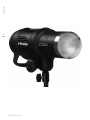
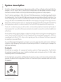
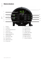
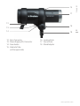
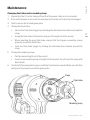
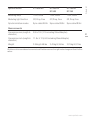
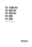
D1 1 000 Air
D1 500 Air
D1 250 Air
D1 500
D1 250
User´s Guide EN
This user guide is available in other languages at profoto.com/support
CN – 其他语言版本的用户指南可从profoto.com/cn/support下载
DE – Das Bedienungs-Handbuch is auch in anderen Sprachen verfügbar unter profoto.com/de/support
ES – Esta guía de usuario está disponible en otros idiomas en profoto.com/support
FR – Ce manuel d’utilisation est également disponible en d’autres langues sur profoto.com/fr/support
IT – Questa guida per gli utenti è disponibile in altre lingue su profoto.com/it/support
JP – このユーザーガイドはprofoto.com/ja/supportに他の言語でもご用意しています。
RU – Инструкция пользователя на других языках доступна на profoto.com/ru/support
Profoto D1
2
www.profoto.com
Profoto D1
Thank you for choosing Profoto
Thanks for showing us your confidence by investing in a D1 unit.
For more than four decades we have sought the perfect light.
What pushes us is our conviction that we can offer even better
tools for the most demanding photographers.
Before our products are shipped we have them pass an
extensive and strict testing program. We check that each
individual product comply with specified performance, quality
and safety. For this reason our flash equipment is widely used in
rental studios and rental houses worldwide, from Paris, London,
Milan, New York, Tokyo to Cape Town.
Some photographers can tell just from seeing a picture, if
Profoto equipment has been used
Professional photographers around the world have come to
value Profoto’s expertise in lighting and light-shaping. Our
extensive range of Light Shaping Tools offers photographers
unlimited possibilities for creating and adjusting their own
light.
Every single reflector and accessory creates its special light and
the unique Profoto focusing system offers you the possibility to
create your own light with only a few different reflectors.
Enjoy your Profoto product!
www.profoto.com
3
Profoto D1
4
Safety instructions
Safety Precautions!
Do not operate the equipment before studying the instruction manual and the accompanying safety. Make
sure that Profoto Safety Instructions is always accompanied the equipment! Profoto products are intended
for professional use! Generator, lamp heads and accessories are only intended for indoor photographic
use. Do not place or use the equipment where it can be exposed to moisture, extreme electromagnetic
fields or in areas with flammable gases or dust! Do not expose the equipment to dripping or splashing.
Do not place any objects filled with liquids, such as vases, on or near the equipment. Do not expose the
equipment to hasty temperature changes in humid conditions as this could lead to condensation water
in the unit. Do not connect this equipment to flash equipment from other brands. Do not use flash heads
without supplied protective glass covers or protective grids. Glass covers shall be changed if it has
become visibly damaged to such an extent that their effectiveness is impaired, for example by cracks
or deep scratches. Lamps shall be changed if they are damaged or thermally deformed. When placing
a lamp into the holder ensure not to touch the bulb with bare hands. Equipment must only be serviced,
modified or repaired by authorized and competent service personnel! Warning - The terminals marked
with the flash symbol are hazardous live.
WARNING – Electrical Shock – High Voltage!
Mains powered generator shall always be connected to a mains socket outlet with a protective earthing
connection! Only use Profoto extension cables! Do not open or disassemble generator or lamp head!
Equipment operates with high voltage. Generator capacitors are electrically charged for a considerable
time after being turned off. Do not touch modeling lamp or flash tube when mounting umbrella metal
shaft in its reflector hole. Disconnect lamp head cable between generator and lamp head when changing
modeling lamp or flash tube! The mains plug or appliance coupler is used as disconnect device. The
disconnect device shall remain readily operable. Batteries (battery pack or batteries installed) shall not
be exposed to excessive heat such as sunshine, fire or the like.
Caution – Burn Hazard – Hot Parts!
Do not touch hot parts with bare fingers! Modeling lamps, flash tubes and certain metal parts emit
strong heat when used! Do not point modeling lamps or flash tubes too close to persons. All lamps may
on rare occasions explode and throw out hot particles! Make sure that rated voltage for modeling lamp
corresponds with technical data of user guide regarding power supply!
NOTICE – Equipment Overheating Risk
Remove transport cap from lamp head before use! Do not obstruct ventilation by placing filters, diffusing
materials, etc. over inlets and outlets of the equipment ventilation or directly over glass cover, modeling
lamp or flash tube!
Note about RF!
This equipment makes use of the radio spectrum and emits radio frequency energy. Proper care should
be taken when the device is integrated in systems. Make sure that all specifications within this document
are followed, especially those concerning operating temperature and supply voltage range. Make sure the
device is operated according to local regulations. The frequency spectrum this device is using is shared
with other users. Interference can not be ruled out.
Final Disposal
Equipment contains electrical and electronic components that could be harmful to the environment.
Equipment may be returned to Profoto distributors free of charge for recycling according to WEEE. Follow
local legal requirements for separate disposal of waste, for instance WEEE directive for electrical and
electronic equipment on the European market, when product life has ended!
www.profoto.com
System description....................................................................................................6
Profoto Air....................................................................................................6
Profoto Air Remote..........................................................................7
Profoto Air Sync...............................................................................7
Profoto Air USB................................................................................7
Profoto Studio..................................................................................7
Nomenclature .......................................................................................................8
Functionality .....................................................................................................10
Power supply.................................................................................10
Energy control...............................................................................10
Modeling light...............................................................................10
Sync signaling...............................................................................10
Ready signaling.............................................................................11
Ready indicator/Test function.........................................................11
Flash before ready.........................................................................11
Remote control..............................................................................12
Color temperature.........................................................................12
Reflector........................................................................................12
Umbrella........................................................................................12
Operating instructions..............................................................................................13
Stand mounting.............................................................................13
Mounting of external reflector........................................................13
Umbrella mounting........................................................................13
Glass cover mounting....................................................................13
Power connection..........................................................................13
Energy level setting.......................................................................13
Modeling light setting....................................................................14
Ready signaling setting..................................................................14
Sync via cable...............................................................................15
Sync via IR....................................................................................15
Sync via radio (D1 without Profoto Air)...........................................15
Sync via radio (D1 with Profoto Air)................................................15
Radio settings (D1 with Profoto Air)................................................15
Turn off unit...................................................................................16
Maintenance .....................................................................................................17
Changing flash tube and/or modeling lamp....................................17
Changing built-in fuse...................................................................18
Adaptive thermal control..........................................................................................19
Technical data .....................................................................................................20
www.profoto.com
Profoto D1
Table of Contents
5
Profoto D1
6
System description
Profoto’s 40 years of experience in developing state-of-the-art flash units is built into the
design of the D1 units. The D1 family fully complies with the demand for durable, tough,
fast and consistent flash units that professional photographers of today require.
The D1 unit is available in 250, 500 and 1000 Ws versions, all with integrated Profoto
Air functionality. The 250 and 500 Ws versions are also available without Profoto Air. The
unit is fully digital, to ensure a consistency in flash-to-flash color temperature and flash
energy. The dual mode SMPS (Switch Mode Power Supply) charging technology ensures
the flash-to-flash precision. The 7 f-stop power range gives all the power the demanding
photographer needs for creative freedom, to shoot with high speed and full open lens.
The built-in reflector gives you full control, minimal stray light and maximal light output.
It is designed for use with soft boxes and umbrellas and for use with or without additional
reflectors.
Short flash duration gives images a crisp feel and the fast recycling time means that you
never have to wait for the flash. You will always get the image quality you want. All this in
a package that offers 1/10 f-stop control, giving you the confidence that the images will
be exactly as you want them.
As a professional photographer, you have your own special style and needs. Profoto’s
extensive Light Shaping Tools system fits perfectly with the D1, enabling you to shape the
light your own way.
Profoto Air
Profoto Air is a system for convenient remote control of flash generators. The Profoto
Air system is operating on one of eight selectable radio channels on the 2.4 GHz radio
frequency band, for world wide use.
All Profoto flash generators with Profoto Air inside can be controlled via the Profoto Air
system. Products with integrated Profoto Air functionality are marked with the Profoto
Air symbol.
Profoto Air symbol
www.profoto.com
Profoto Air Remote offers remote control of your D1 Air units and synchronization of all your
D1 units at your camera or in your hand. The device controls practically an infinite number
of D1 units in up to six groups, either all at once in Master mode, or in individual groups.
Profoto D1
Profoto Air Remote
Profoto Air Sync
Profoto Air Sync allows synchronization of practically an infinite number of D1 units, with
the same high performance as Profoto Air Remote.
Profoto Air USB
The Profoto Air USB device is a USB 2.0 transceiver, which connects your D1 Air unit to your
PC or Mac via a wireless connection. Profoto Air USB allows control of your light from as far
away as 300 m/1000 ft (free line of sight).
Profoto Studio
Profoto Studio is a software solution for both PC and Mac, which gives you full control of
all your D1 Air units from your computer. You can control each unit individually or group
them to control multiple units at one time. You can save customer lighting setups for use
at a later time.
www.profoto.com
7
Profoto D1
Nomenclature
7
1
2
8
8
3
4
9
10
5
11
6
1.Display
2. On Button
3. Power Supply Indicator
4. Test Button
5. Ready Indicator
6. Channel Set Button
7. Setting Knob
8. SLAVE SETTING
8a. Slave Button
8b. RADIO Indicator
8c. IR Indicator
www.profoto.com
9. READY SETTING
9a. Ready Button
9b. BEEP Indicator
9c. DIM Indicator
10. MODEL SETTING
10a.Model Button
10b.PROP Indicator
10c.FREE Indicator
11. Model Set Button
17
Profoto D1
15
12
16
13
14
12. Sync Connector
13. Power Supply (AC) Connector
14. Fuse Holder
15. Umbrella Tube
(on the upper side)
18
16. Locking Knob
17. Zoom Scale
18. Stand Adapter
www.profoto.com
9
Profoto D1
Functionality
Power supply
The D1 unit can be connected to 100-120 VAC or 200-240 VAC, 50-60 Hz. The unit
automatically senses and adapts to the supplied voltage and frequency. The power supply
fuses must not be smaller than specified in the section Technical data.
Most gas generators with an output of 800 W constant load, or more, can power the D1
unit. Thanks to the two stage SMPS (Switch Mode Power Supply) technology, no ProGas
unit is needed.
10
Warning:
Never use ordinary household extension cords to elongate the power cable. They may overheat. Always unwind cord
reel extension winders fully before use. Contact your Profoto dealer for proper equipment.
Due to the two stage SMPS technology, the D1 could make a audible sound during the
recharge cycle. This is fully normal and could be seen as the sign of power being charged
into the unit.
Energy control
The current energy level of the flash light is shown in the Display [1] in f-stop scale. The
maximal energy (100%) is shown as 10.
The Setting Knob [7] is used to adjust the energy level, in 1/10 f-stop or 1 f-stop
increments.
Modeling light
The Model Button [10a] is used to select one of three modeling light alternatives:
• PROP: The modeling light intensity is automatically adjusted to correspond to the
energy level of the flash light.
• FREE: The modeling light intensity is manually set, free from any connection to the
energy level of the flash light.
• OFF: No modeling light.
The Model Set Button [11], in combination with the Setting Knob [7], is used to change the
level of the free modeling light.
Sync signaling
The D1 unit can be synchronized in different ways; via cable, via infrared (IR) light or via
the Profoto Air radio system.
• The 5 meter sync cable can without restrictions be elongated with a sync extension
cable. The Profoto sync interconnection cord or so called “hard wiring” may be
used.
www.profoto.com
• The Profoto Air radio system is fully integrated in the D1 Air units, allowing radio
synchronization via a Profoto Air Remote or Profoto Air Sync device connected to the
camera, or via the Profoto Air USB device connected to a computer with the Profoto
Studio program.
Profoto D1
• The built-in IR receiver senses the flash release as well as IR signals from most IR sync
transmitters.
• D1 units without integrated Profoto Air functionality can be equipped with a Profoto Air
Remote or Profoto Air Sync device acting as receiver, enabling radio synchronization
via another Profoto Air Remote or Profoto Air Sync device connected to the camera.
Ready signaling
Ready signaling is used to indicate when the unit is fully charged. The Ready Button [9a]
is used to select one of four ready signaling alternatives:
• BEEP: A clear “beep” will sound to indicate that the charging of the unit is completed.
This setting also enables the control panel sounds, which indicates that a button is
pressed or the Setting Knob is turned.
• DIM: The modeling light will be turned off when the unit is being charged, and turned
on again when the charging is completed. This setting also disables the control panel
sounds.
• BEEP-DIM: The modeling light will be turned off when the unit is being charged, and
turned on again when the charging is completed. A clear “beep” will also sound to
indicate that the charging is completed. This setting also enables the control panel
sounds.
• OFF: No ready signal. This setting also disables the control panel sounds.
Ready indicator/Test function
The Ready Indicator [5] is illuminated when the unit is fully charged and ready to flash.
The Test Button [4] is used to test that all light settings are correct and that the functionality
is as expected. When the Test Button [4] is pressed, the unit will flash and the Ready
Indicator [5] will be turned off while recharging. When the charging of the unit is completed,
the Ready Indicator [5] will be illuminated again.
Flash before ready
The “Flash before ready” function makes it possible to flash before the charging of the unit
is ready and fully completed. When a flash is released before the unit is 100% recharged,
a long “beep” will sound, indicating an under exposed frame. Naturally the flash light may
not correspond fully to the set value.
www.profoto.com
11
Profoto D1
Remote control
Wireless remote control is available for D1 Air units, using the Profoto Air Remote device or
the Profoto Air USB device in combination with the Profoto Studio software.
For more information about remote control, please refer to the User’s Guides for Profoto
Air Remote or Profoto Air USB/Profoto Studio.
Color temperature
A frosted glass plate is included in the D1 delivery. It gives, in combination with the
flash tube, a recommended color temperature for daylight type film. Distinctive color
temperature adjustments can be obtained by using glass covers with different coatings.
12
Reflector
D1 is equipped with a built-in reflector, providing full control, minimal stray light and
maximal light output. By mounting an external reflector and placing it in different positions,
using the Zoom Scale [17], several light shapes can be created for each lighting purpose.
Umbrella
D1 is equipped with an umbrella tube that is suited for most umbrellas on the market. The
diameter of the umbrella shaft must be between 7 mm and 8 mm. When an umbrella is
used, it is not possible to mount an external reflector at the same time.
www.profoto.com
Stand mounting
1. Mount and fasten the D1 unit on the stand using the locking knob on the Stand Adapter
[18].
Profoto D1
Operating instructions
2. The unit can be directed upwards/downwards when the Locking Knob [16] is
loosened. Fasten the Locking Knob [16] when the unit is correctly directed.
Mounting of external reflector
1. Unlock the clasp on the external reflector.
2. Slide the reflector onto the D1 unit. Use the Zoom Scale [17] to place the reflector in
the desired position.
3. Secure the reflector by locking the clasp.
Umbrella mounting
1. Slide the umbrella shaft into the Umbrella Tube [15] on the D1 unit.
2. After a few centimeters, there will be more friction. Continue to slide the umbrella shaft
to optimise the light into the umbrella.
Glass cover mounting
1. Ensure that the D1 unit is turned off and that the power cable is not connected.
2. If the unit has been in use, wait five minutes to allow the unit to be fully discharged (the
autodump function).
3. Gently remove the frosted glass plate.
4. Carefully fit the glass cover in place. Make sure that the safety pins fit properly into the
slot of the glass cover.
Power connection
1. Connect the power cable to the Power Supply (AC) Connector [13] on the D1 unit and
to the mains power supply outlet.
2. The Power Supply Indicator [3] will be red, indicating that the unit is receiving power
but is in standby mode.
3. Press the On Button [2].
4. The Power Supply Indicator [3] will now be green.
Energy level setting
1. Use the Setting Knob [7] to change the energy level of the flash light:
Turn the Setting Knob [7] clockwise to increase the energy level in 1/10 f-stop
increments and counter-clockwise to decrease.
Press and hold down the Setting Knob [7] and turn the knob clockwise to increase the
energy in 1 f-stop increments and counter-clockwise to decrease.
www.profoto.com
13
Profoto D1
Modeling light setting
1. Use the Model Button [10a] to select the modeling light:
a. To select proportional modeling light, press and hold down the Model Button [10a]
until the PROP Indicator [10b] is illuminated.
b. To select free modeling light, press and hold down the Model Button [10a] until
the FREE Indicator [10c] is illuminated. The energy level of the latest selected free
modeling light setting will be activated.
14
c. To turn off the modeling light, press the Model Button [10a]. Both the PROP
Indicator [10b] and the FREE Indicator [10c] will be turned off. Press the Model
Button [10a] again to turn on the modeling light.
Change the level of the free modeling light:
1. Verify that free modeling light setting is selected (the FREE Indicator [10c] shall be
illuminated when the modeling light is turned on).
2. Press the Model Set Button [11]. The Display [1] will start flashing, showing the current
energy level of the Free modeling light.
3. While the Display [1] is flashing, use the Setting Knob [7] to change the energy level:
a. Turn the Setting Knob [7] clockwise to increase the energy level in 1/10 f-stop
increments and counter-clockwise to decrease.
b. Press and hold down the Setting Knob [7] and turn the knob clockwise to increase
the energy in 1 f-stop increments and counter-clockwise to decrease.
4. Wait until the Display [1] stops flashing. (The Display [1] will now show the energy level
of the flash light.)
Ready signaling setting
1. Use the Ready Button [9a] to select the ready signaling:
a. To select sound signaling, press and hold down the Ready Button [9a] until the
BEEP Indicator [9b] is illuminated.
b. To select light signaling, press and hold down the Ready Button [9a] until the DIM
Indicator [9c] is illuminated.
c. To select both sound and light signaling, press and hold down the Ready
Button [9a] until both the BEEP Indicator [9b] and the DIM Indicator [9c] are
illuminated.
d. To turn off the ready signaling, press the Ready Button [9a]. Both the BEEP
Indicator [9b] and the DIM Indicator [9c] will be turned off. Press the Ready
Button [9a] again to turn on the ready signaling.
www.profoto.com
Sync via IR
1. Press and hold down the Slave Button [8a] until the IR Indicator [8c] is illuminated.
Profoto D1
Sync via cable
1. Connect a sync cord from the camera to the Sync Connector [12] on the D1 unit.
Sync via radio (D1 without Profoto Air)
1. Connect a Profoto Air Remote or Profoto Air Sync device (Receiver) with a cable to the
Sync Connector [12] on the D1 unit.
2. Follow the instructions for generators without built-in Profoto Air receiver in the
Profoto Air Remote/Profoto Air Sync User’s Guide.
Sync via radio (D1 with Profoto Air)
1. Press and hold down the Slave Button [8a] until the RADIO Indicator [8b] is illuminated.
2. Select radio channel by following the Radio settings instructions below.
3. Connect a Profoto Air Remote or Profoto Air Sync device to the camera.
4. Follow the instructions for generators with built-in Profoto Air receiver in the Profoto
Air Remote/Profoto Air Sync User’s Guide.
Radio settings (D1 with Profoto Air)
For sync via radio, the same radio channel has to be set on the D1 unit and the Profoto Air
device or the Profoto Studio program.
For remote control using Profoto Air Remote, the same radio channel and group have to be
set on the D1 unit and the Profoto Air device.
For remote control using Profoto Air USB and Profoto Studio the same radio channel has to
be set on the D1 unit and in the Profoto Studio program.
1. Verify that the RADIO Indicator [8b] is illuminated on the D1 unit.
2. Press the Channel Set Button [6]. The Display [1] will start flashing, showing the
current radio channel number to the left and the radio group letter to the right.
3. While the Display [1] is flashing, turn the Setting Knob [7] clockwise to increase the
radio channel number (1 to 8) and counter-clockwise to decrease the number.
4. While the Display [1] is flashing, press and hold down and turn the Setting Knob [7]
clockwise to increase the group letter (A to F) and counter-clockwise to decrease the
letter.
5. Wait until the Display [1] stops flashing. (The Display [1] will now show the energy level
of the flash light.)
For radio channel and group settings on the Profoto Air devices and the Profoto Studio
program, please refer to the corresponding User’s Guide.
www.profoto.com
15
Profoto D1
Turn off unit
All settings will remain when the unit is in standby mode. If the power cable is removed,
the modeling light will revert to the default settings; the modeling light will be turned off
and the energy level of the free modeling light will be set to 10.
1. Press the On Button [2] to turn off the power.
2. The Power Supply Indicator [3] will be red, indicating that the unit is receiving power
but is in standby mode.
3. Remove the power cable.
16
www.profoto.com
Changing flash tube and/or modeling lamp
1. Ensure that the D1 unit is turned off and that the power cable is not connected.
Profoto D1
Maintenance
2. If the unit has been in use, wait five minutes to allow the unit to be fully discharged.
3. Gently remove the frosted glass plate.
4. Change the flash tube:
• Unlock the flash tube trigger by unfolding the stainless steel ribbons around the
clasp.
• Grasp the flash tube in the bottom and pull it straight out of the socket.
• When inserting the new flash tube, ensure that the trigger connection clasps
properly around the flash tube.
• Lock the flash tube trigger by folding the stainless steel ribbons around the
clasp.
5. Change the modeling lamp:
• Pull the lamp straight out of the socket.
• Insert a new modeling lamp, straight into the socket. Do not touch the lamp with
bare hands.
6. Carefully fit the glass plate in place, with the frosted side inwards. Make sure that the
safety pins fit properly around the glass plate.
Clasp
Flash tube
Modeling lamp
www.profoto.com
17
Profoto D1
Changing built-in fuse
1. Ensure that the D1 unit is turned off and that the power cable is not connected.
2. If the unit has been in use, wait five minutes to allow the unit to be fully discharged (the
autodump function).
3. Pull out the Fuse Holder [14] from the unit and remove the old fuse.
4. Push the new fuse all the way into the Fuse Holder. Only use recommended fuse, see
section Technical data.
5. Fit the Fuse Holder in place, by gently pushing until the holder snaps in place.
18
www.profoto.com
The D1 unit is equipped with an adaptive thermal control system. If there is risk for
over heating of the unit, caused by either heavy use or abnormal external influence, the
thermal control system will automatically protect the unit from damage. A microprocessor
supervises and controls the unit, based on input from four thermal sensors. If the sensors
report an increase in temperature, the microprocessor automatically takes measures
to protect the unit. The first measure is to increase the fan speed. If the fan at full speed
cannot bring the temperature down, the modeling light will automatically be turned off
during recharging. Next step is to turn off the modeling light completely and at the same
time slow down the recharging. Eventually the recharging will stop completely. After a
while, when the temperature has decreased sufficiently, the unit will start recharging at a
normal pace. This automatic protection will only interfere under extreme conditions, such
as when the air vents are blocked.
Depending on version, the D1 unit is designed to withstand up to 1000 full power flashes
during one hour. However, it is not recommended to run harder than necessary due to the
lifetime of the flash tube.
If a defective flash head – for example with a broken or misfiring flash tube – is used, after
releasing the flash a long beep signal will indicate malfunction/underexposure.
Notice:
The air vents of the unit must never be blocked or covered in any way. Never store your flash equipment in a car on
a hot and sunny day. Never use a D1 unit that is placed inside a case or transport box. Avoid storing the unit close or
below the freezing point. A cold unit may not work properly or may even brake and will lose capacity (flash output).
There is also a risk of failure because of condensation when a cold generator is moved to a warmer surrounding. Do
not expose any flash equipment to wet or humid environments or extreme electro-magnetic fields.
www.profoto.com
Profoto D1
Adaptive thermal control
19
Profoto D1
20
Technical data
D1 1000 Air
D1 500 Air
D1 250 Air
D1 500
D1 250
Specifications
D1 1000 Air
D1 500 Air
D1 500
D1 250 Air
D1 250
Energy (Ws/J)
1000
500
250
Power range f-stop
7
7
7
Ws
15.6-1000
7.8-500
3.9-250
Power range
1/1-1/64
1/1-1/64
1/1-1/64
Power increments
1/10
1/10
1/10
Flash duration t0.5 minmax power
1/700-1/1800
1/1000-1/2600
1/1400-1/3700
Recycling 230V
0.2-2.0
0.2-0.95
0.2-0.65
Recycling 120V
0.2-2.0
0.2-0.95
0.2-0.65
Color temperature
consistency, K
+/- 30
+/- 30
+/- 30
Color temperature, K
5600
5600
5600
Energy precision (flash-to- ±0.05
flash) f-stop
±0.05
±0.05
Light spread with built-in
reflector
77 degrees
77 degrees
77 degrees
Multi voltage
Yes
Yes
Yes
Power supply fuse, 200240VAC
6 amp
6 amp
6 amp
Power supply fuse, 100120VAC
10 amp
10 amp
10 amp
Built-in fuse
T10AH 5x20
T10AH 5x20
T10AH 5x20
www.profoto.com
D1 1000 Air
D1 500 Air
D1 500
D1 250 Air
D1 250
Modeling lamp
120V, 300W
120V, 300W
120V, 300W
Modeling light function
Off, Prop, Free
Off, Prop, Free
Off, Prop, Free
Synchronization modes
Sync cable/IR/Air Sync cable/IR/Air Sync cable/IR/Air
Profoto D1
Specifications
Measurements
Dimensions mm (length &
diameter)
300 x 130 (170 including Stand Adapter)
Dimensions inch (length &
diameter)
11.8 x 5.12 (6.69 including Stand Adapter)
Weight
2.94 kg/6.48 lbs
2,43 kg/5,36 lbs
21
2,23 kg/4,91 lbs
All data are to be considered as nominal and Profoto reserves the right make changes without further
notice.
www.profoto.com
Profoto D1
22
Appendix
Battery mode
The D1 can be set to low power mode enabling it to be supplied by a battery inverter. By
reducing the current and using the D1 in battery mode, the Profoto BatPac can supply up
to four D1 at the same time. If the D1 are used in standard mode, the BatPac can supply
max. two D1 at the same time with a limited performance.
Operating instructions
To toggle the battery mode, go to standby and press the “Model” button for 10s. The display
will toggle between “bt” (battery mode) or “- -“ (normal mode). To activate this function, the
generator needs to be restarted by removing and reconnecting the mains supply.
Power on mode
The D1 normally starts to standby when mains are connected. In some cases the user may
want the D1 to turn on immediately and this can be done by changing the power on mode.
Operating instructions
To toggle the power on mode, go to standby and press the “Test” button for 10s. The display
will toggle between “P0” (power on to standby) or “P1” (power on immediately). The
next time the generator is started it will enter the chosen mode. Note! In “P1” mode, the
generator will go to whatever the generator was set to when mains was last disconnected.
If it was in standby, it will go to standby, if it was turned on, it will be turned on.
Display mode
If the D1 is mounted upside down in a fixed installation, reading the power setting on the
display may be awkward. To solve this, the user has the option to change the display mode
which will change the orientation of the display.
Operating instructions
To toggle the display mode, go to standby and press the “Slave” button for 10s. The display
will toggle the letters “AA” with the right side up, or upside down, indicating the display
orientation.
www.profoto.com
Profoto D1
Remote mode
The remote control Head On / Head Off command is a group command used for turning
off / on lamp heads on Profoto Generators. However useful for larger studio setups, this
command may be changed to work as Power On / Power Off instead.
Operating instructions
To make the generator read a Head On / Head Off command as Power On / Power Off, go to
standby and press the “Ready” button for 10s. The display will toggle between “A0” (Head
On / Head Off) or “A1” (Power On / Power Off).
Remote control
When the Head Off command has been used with the remote control or Profoto Studio, the
user also has the option to turn on the head via the generator interface by pressing either
the knob or entering/leaving standby.
The user has the option to turn off radio communication completely by turning off radio
sync on the generator panel interface. By doing this he turns off all possibility to control the
generator via remote control or Profoto Studio. A user also has the option to turn off radio
sync from Profoto Studio but this will not turn off the radio communication.
www.profoto.com
23
P.O. Box 1264
SE-172 65 Sundbyberg, SWEDEN
Visiting address:
Landsvägen 57, Sundbyberg
Phone +46 8 447 53 00
[email protected]
www.profoto.com
344091-1-320. Printed in Sweden.
Technical data and product information are subject to change without notice.
Profoto AB