1
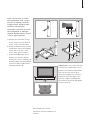
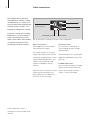
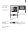
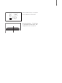
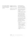
BeoLab 7-1
BeoLab 7-2
Guide
CAUTION: To reduce the risk of
electric shock, do not remove
cover (or back).
No User-serviceable parts inside.
Refer servicing to qualified
service personnel.
WARNING: To prevent fire or electric
shock, do not expose this appliance to
rain or moisture. Do not expose this
equipment to dripping or splashing
and ensure that no objects filled with
liquids, such as vases, are placed on
the equipment.
To completely disconnect this equipment from the AC Mains, disconnect
the power supply cord plug from the
AC receptacle.
This symbol indicates that a
dangerous voltage constituting
a risk of electric shock is present within this unit.
This symbol indicates that there
are important operating and
maintenance instructions in the
literature accompanying this
unit.
Cautions!
– Make sure that the loudspeaker
is placed and connected in
accordance with the instructions
in this Guide.
– Do not attempt to open the loudspeaker. Leave such operations
to qualified service personnel!
– The loudspeaker is designed for
indoor use in dry, domestic
environments only, and for use
within a temperature range of
10–40º C (50–105º F).
– In order not to block the sound
emitting from the rear bass reflex
ports and the bass units on the
bottom, leave a minimum of
6 cm (2½") free space behind and
below the loudspeaker.
– Always place the loudspeaker in
a horizontal position, and do not
place any items on it.
– Prolonged listening at high
volume levels may cause hearing
damage!
Daily use
When you have finished setting
up the loudspeaker as described
on the following pages, connect
the entire system to the mains.
Cleaning the loudspeaker
Clean dusty surfaces using a dry,
soft cloth. If necessary, remove
grease stains or persistent dirt with
a lint-free, firmly wrung cloth,
Loudspeaker protection
dipped in a solution of water
The loudspeaker is equipped with a containing only a few drops of
thermal protection system which
mild detergent, such as washingprevents damage from overheating. up liquid.
If an error occurs – or the speaker
units become overheated – the
The loudspeaker front grill may be
system automatically switches the
cleaned with a vacuum cleaner with
loudspeaker to standby.
a soft brush nozzle, and set to the
lowest level.
To restore the sound:
> Disconnect the loudspeaker from Never use alcohol or other solvents to
the mains.
clean any parts of the loudspeaker!
> Allow the system time to reset or
cool down (approximately 3–5
Switching on and off
minutes).
When you switch on your Bang &
> Reconnect the loudspeaker to the Olufsen system, the loudspeaker
mains.
switches on simultaneously, and
when you switch the system off
Should the problem persist, contact again the loudspeaker also switches
your Bang & Olufsen retailer.
off.
3
Caution: Handle the loudspeaker
front grill with great care. Dents
and scratches are not covered by
the guarantee!
Set up the loudspeaker
4
We recommend that you follow
this procedure:
– Disconnect your Bang & Olufsen
system from the mains.
– Mount the loudspeaker to the
Bang & Olufsen stand or wall
bracket as explained on the next
page.
– Connect the loudspeaker as
explained in ‘Cable connections’
(pp. 6–7).
– Set the POSITION switch to the
correct setting. This is explained
in ‘Adapt the loudspeaker to
your room’ (pp. 8–9).
– Connect the entire system to the
mains again.
In order not to dent or scratch the
loudspeaker front grill, we
recommend that you lift the loudspeaker by holding on to the two
bass units on the bottom. Do not
support the loudspeaker holding
the loudspeaker front grill!
‘Type 1 bracket’
100 cm
39"
BeoLab 7-1
‘Type 2 bracket’
124 cm
49"
BeoLab 7-2
BeoLab 7 brackets: The loudspeaker must be fastened to one of
the brackets shown here, and on a
suitable Bang & Olufsen stand or
wall bracket.
BeoLab 7-1: Always use the ‘type 1
bracket’.
BeoLab 7-2: Use the ‘type 2
bracket’ when the loudspeaker will
be fastened to one of the ‘doublecolumn’ Bang & Olufsen stands.
However, use the ‘type 1 bracket’
if the loudspeaker will be fastened
to a wall bracket – for example
below a BeoVision 4 screen.
5
Here is shown how to fasten
the loudspeaker with a ‘type 1
bracket’ to a Bang & Olufsen
‘single-column’ stand (or wall
bracket). Use the same
procedure if you wish to fasten
the loudspeaker to a Bang &
Olufsen ‘double-column’ Stand
– with a ‘type 2 bracket’.
a Remove the small cover (if any)
on the stand. Press the cover as
shown, and it will come loose.
b Fasten the bracket to the stand or
wall bracket. Use the two longest
screws (M5 × 25 mm) – four
screws for a ‘type 2 bracket’.
c Fasten the loudspeaker to the
bracket. Use the two shortest
screws (M5 × 8 mm). However, do
not fully tighten the screws before
you have made the adjustments
mentioned below (d).
a
c
b
c
d
d
c
c
NOTE! BeoVision 7 and its
accessories are not available on all
markets.
Adjustments: First, make sure that
the television is adjusted to a level
position on its stand or wall bracket!
Then use the two screws (d) to
adjust the loudspeaker so that it is
parallel to the lower edge of the
television. Align the loudspeaker
front with the television and tighten
the two screws (c).
Cable connections
6
The loudspeaker is primarily
intended to be used in a setup
with BeoVision 7*. It may, however, be used with other Bang &
Olufsen systems as well – for
example in a BeoVision 4 setup.
If used in a setup not including
BeoVision 7, you will require a
mains cord and a Power Link
cable. These cables are available
as optional accessories from
your Bang & Olufsen retailer.
Mains connection
to BeoVision 7
POSITION switch
Cable clamp
The socket panel is located on the rear of the loudspeaker.
Mains connections
The loudspeaker has two sockets
concerning mains supply.
The socket marked ~ is for mains
supply input (connection from the
wall outlet), and the other is a mains
supply output to BeoVision 7 (this
socket is not available on loudspeakers intended for the USmarket).
Note: The mains cord from the wall
outlet must be fastened to the
cable clamp on the loudspeaker –
as shown on the next page.
*NOTE! BeoVision 7 and its
accessories are not available on all
markets.
POWER LINK
socket
POSITION switch
This switch has two settings: F
(Free-standing position) and W
(Wall position).
Which setting to use is explained in
‘Adapt the loudspeaker to your room’
(pp. 8–9).
POWER LINK socket
Use this socket to connect the loudspeaker to one of the Power Link
sockets on the Bang & Olufsen
system – see the next page.
7
Connection to BeoVision 7 …
Connect the loudspeaker to one of
the Power Link sockets on the left
BeoVision 7 socket panel.
BeoVision 7
For further information about the
BeoVision 7 socket panels, refer to
the Guides enclosed with the
product.
BeoLab 7
Cable clamp: For safety reasons,
the mains cord from the wall outlet
must be secured to the loudspeaker.
To do so, tug the cord behind the
clamp.
The two mains cords and the
Power Link cable are enclosed with
BeoVision 7.
Connection to other Bang &
Olufsen systems …
Use a Power Link cable of the
correct type to connect the loudspeaker to a Power Link socket on
the Bang & Olufsen system.
For further information, refer to the
Guide enclosed with the Bang &
Olufsen system.
Power Link
Mk 3
Power Link cable: Do not use a
cable of the older type, as this will
cause noise, and therefore not give
optimum sound quality! The new
type has a triangular mark on the
plug.
Adapt the loudspeaker to your room
8
When a loudspeaker is placed
in a corner or close to a wall,
the bass level is boosted
compared to the bass level from
a loudspeaker placed in a more
free-standing position.
To remove this excessive bass
boost, use the POSITION switch
to ensure that the bass level
suits the placement of the
loudspeaker. The appropriate
switch setting depends on the
distance from the loudspeaker
to the walls and corners of the
room.
The POSITION switch
• F (Free-standing position)
Use this setting if the loudspeaker
is placed so that the front grill is
more than 50 cm (20") from the
rear wall, for example on one of
the floor or table stands.
• W (Wall position)
Use this setting if the loudspeaker
is placed so that the front grill is
less than 50 cm (20") from the rear
wall.
Always use this setting if the loudspeaker is placed on any of the wall
brackets, but also when placed on
one of the stands – close to the
rear wall.
If the loudspeaker is fitted to one
of the table stands – and you have
chosen to place it on the floor – you
should set the POSITION switch to
W.
F
W
9
The POSITION switch is located on
the loudspeaker socket panel.
F
W
How to measure … The distance
is measured as shown here – the
loudspeaker seen from above.
10
To get access to the approval
labels, remove the loudspeaker
front grill:
Push the front grill towards the left
(~ 10 mm). The front grill can now
be removed.
Note: When attaching the front
grill again, make sure that all five
‘attach-points’ engage with the
corresponding brackets on the loudspeaker. Do not attempt to mount
the front grill upside down (marked
).
on the rear by
Caution: Handle the loudspeaker
front grill with great care. Dents
and scratches are not covered by
the guarantee!
For the Canadian market only!
This class B digital apparatus meets
all requirements of the Canadian
Interference-Causing Equipment
Regulations.
This product fulfils the
conditions stated in the
EEU directives 89/336 and 73/23.
Technical specifications, features
and the use thereof are subject to
change without notice!
3509114
0508
For the US-market only!
NOTE: This equipment has been
tested and found to comply with
the limits for a class B digital device,
pursuant to part 15 of the FCC Rules.
These limits are designed to provide
reasonable protection against harmful interference in a residential
installation.
This equipment generates, uses and
can radiate radio frequency energy
and, if not installed and used in
accordance with the instructions,
may cause harmful interference to
radio communications. However,
there is no guarantee that interference will not occur in a particular
installation. If this equipment does
cause harmful interference to radio
or television reception, which can be
determined by turning the equipment off and on, the user is
encouraged to try to correct the
interference by one or more of the
following measures:
– Reorient or relocate the receiving
antenna.
– Increase the separation between
the equipment and receiver.
– Connect the equipment into an
outlet on a circuit different from
that to which the receiver is
connected.
– Consult the retailer or an
experienced radio/TV technician
for help.
Printed in Denmark by Bogtrykkergården a-s, Struer
www.bang-olufsen.com