1
MOD
TAP Modular Preamplifier System
User Manual
Thank you for choosing the TAP Modular Pre-amplifier system . Your ownership experience is very
important to us so if at any time you have any questions please contact us directly at:
(604)538-9812
www.bentaudio.com
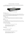
An Introduction to the TAP Modular Passive Pre-amp
The TAP Modular pre-amplifier is designed to offer features never before available in a
passive pre-amplifier. It is important to note however that NONE of these features adds complexity to
the signal path. Throughout the design of the TAP pre-amp system we focused on maintaining a pure
and direct signal path between your source and your amplifier. Keeping the signal path clean and
simple allows us to use only the finest parts throughout.
For many Systems our single box TAP-X Autoformer Pre-amp will be the best choice. There are
however systems that can make use of the TAP Modular System parts to put together a system that better suits
your pre-amp needs. Lower cost single input systems and more exotic controller options make it a flexible
alternative to the single box TAP-X.
The most basic form of TAP Modular Pre-amp is the Micro-TAP system with two Bent Units– a single
input resistor based passive pre-amp. A separate document is designed just to cover this system and can be found
on the website under the Micro-TAP section.
To add additional attenuation channels (for 100% passive multichannel systems) to a TAP-X
Autoformer Pre-amp you simply install the Expansion Module in the TAP-X (or order your TAP-X with it
installed) and then plug Bent Units into that Expansion Port. This document can be used to decide on which Bent
Units best suit your application and serve as a hook-up guide when installing them.
This document includes a full description of all TAP Modular Pre-amp components – it serves as a
guide to deciding if a modular system is the right answer for you. It's also a user manual for the TAP Modular
Pre-amp System.
At the heart of the TAP Modular Passive is the Bent Unit – an attenuator module.
All traditional resistor passive pre-amps struggle with driving downstream cables – keeping the pre-amp
to amplifier interconnect as short as possible is critical. The shorter this cable is the better the sonic and
measured performance are. Our goal was to solve this problem entirely by placing the attenuator right at each
amplifier input. This can be done with traditional level controls and can work very well – the classic EVS
Ultimate Attenuators are an excellent implementation of this and would be a good option for a one source budget
system where remote control is not needed. The only problem with this placement was that it was not all that
convenient to adjust levels and remote control was not possible. The TAP Bent Unit system combines the
'correct' placement of the attenuators in an easy to use full function system.
The TAP resistor pre-amp is made up of a TAP system controller and then at least one pair of separate
attenuator modules – to be located at each amplifier input. This results in a remarkable volume control device
with a very clean short signal path including the following features:
–
–
–
–
Very small 1db step size from -60 db up to +0db (unity gain)
100% passive signal path
Full remote control of volume, mute, and right/left balance
Each channel has level trim ability
This document will cover using Bent Units in typical two channel stereo systems. That is by far the
most common setup. Note however that you can include as many Bent Units in your system as you'd like to –
there is no limit. A six channel system for surround sound can be easily constructed using a TAP system
controller and then 6 Bent Units (or 3 Stereo Bent Units).
In this document we'll list the most common Bent Units. There are many other custom Bent Unit
configurations that can be built. We can build custom Autoformer Bent Units or even turn a 6 input TAP-X
Autoformer pre-amp into a Bent Unit – so it could be run from a separate controller like the TRIK. If you don't
see a configuration that suits your system please contact us and chances are we can make one for you.
A few notes about System Connection
The TAP Modular Passive Pre-amp results in quite a few combinations of TAP System Controllers and
Bent Units. Before we dive into descriptions of each unit's features and connections we'll first describe how the
system connects together.
Every TAP system includes a System Controller. This is the user interface of the system - receiving
commands (like volume up, mute, etc) and then displaying the current status of the pre-amp. The System
Controller is the 'front panel' of the pre-amp. Since it is entirely separate from your audio system connections it
can be located anywhere in the listening room.
Every TAP system also has 2 Bent Units (or a single 2 channel Bent Unit). This is where the action is.
The audio signal path is all in this box – separate from the TAP System Controller. This separation is made for
one reason only – to allow the attenuator circuits to be placed right at the amplifier inputs. This keeps that all
important attenuator to amp cable length VERY short.
The TAP system controller connects to the Bent Units via fiber optic cables. We use easy to obtain
standard Toslink cables for this connection. This breaks all electrical connections between the System
Controller and the Bent Units.
Important Note:
The fiber optic cable is NOT used as a digital audio cable! Plastic fiber cables are among the worst
options for a digital connection. The TAP Modular System only uses this cable to send a data packet to the Bent
Unit – telling it what volume to go to, etc. The audio signal is not connected to this cable in any way – in fact the
fiber optic cable can be unplugged while the system is playing music and the music will continue on playing just
fine. The audio signal path is 100% analog and 100% passive.
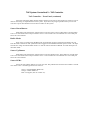
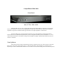
Typical TAP Resistor Passive Pre-amp Example
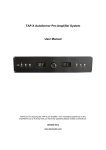
Here is an example of a TAP system using the MicroTAP Controller and one Bent Unit per channel.
This is the most common system configuration. You require only a single interconnect from your source to each
Bent Unit – you can't get a cleaner signal path than that!
This system consists of the following parts:
1- The MicroTAP Controller (with it's power unit)
2- Two Single Input Resistor Bent Units (each with it's power unit)
3- Two Fiber Optic Cables
Here is the general hook-up of a system like this:
The MicroTAP Controller can be placed anywhere in the listening room. The fiber optic cables are
routed to each Bent Unit and each unit in the system powered up via a small 9VDC supply.
Any TAP System Controller could be chosen in place of the MicroTAP Controller as could any other
Bent Unit be used in place of the Mono RCA Bent Units shown.
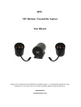
Remote Handset Functions
The remote handset used is the same for all TAP systems. It's functions are described below.
Display On / Off (The Red button on the upper left corner):
Each button press toggles between the 2 display modes. When the display led is on (display mode on)
the display stays on continuously. When the led is off (display mode off ) the display will be on while you are
using the pre-amp / remote functions and then after a short timeout the display turns off for dark listening.
Mute (Center of volume/balance grid):
This button toggle between mute and normal volume modes. When the mute led is on the system is
muted. The mute will be canceled when the volume is adjusted by the remote handset or by the volume knob on
the front of the pre-amp.
Volume UP / Down ('+' and '-'):
The volume up and down buttons step the volume up or down 1 step (1db) per button press or if held
down continuously they continuously adjust volume.
Balance Left / Right ('<' and '>'):
The Balance Left / Right buttons step the volume levels to adjust the balance. This adjustment moves
the sound to the right or left side by 1 volume step per button press (or if held down continuously balance will
progressively move in the desired direction). A sliding / alternating balance is implemented where the level
adjustment to move balance alternates from left or right, etc... This way the overall volume level of the system is
maintained. Also you can slide balance over to one side and then slide it back to the original volume by pressing
the opposite balance button. If you hold the button down constantly while moving back towards center then the
balance will stop as it reaches center. This is handy when adjusting balance back to the middle point.
Source Select Buttons:
The buttons labeled '1' through '6' on the bottom portion of the remote handset directly access each of
the 6 source inputs. This only applies to Stereo 6 Input Bent Units. These direct buttons (rather than next/prev)
are used to make sure that macro functions programmed into a (user supplied) advanced programmable handset
function repeatably.
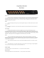
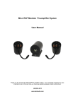
TAP System Controller #1 – The MicroTAP Controller
This is a small low cost single display system controller. The MicroTAP Controller has volume up and
volume down buttons on the front panel. All TAP system functions operate via the supplied remote handset as
described above.
Size: 3-1/2”W x 4-1/4”H x 4-1/4”D
Volume Up:
Volume up can be run via the upper push button on the MicroTAP Controller or via the volume up
button on the remote handset.
Volume Down:
Volume Down can be run via the lower push button on the MicroTAP Controller or via the volume
down button on the remote handset.
Balance Right / Balance Left:
Even though the MicroTAP Controller only has a single 2 digit level display it can still adjust right/left
balance using the remote handset < and > buttons. For user feedback of balance there are 2 small leds just above
the display. If balance is centered then both leds are off. As balance is adjusted to the right the rightmost led will
turn green then orange and finally red as the balance is adjusted further to the right side. The left led behaves the
same way as balanced is adjusted to the left side.
Mute:
If the mute button on the remote handset is pressed the display will change to two dashes ('--') and the
system will mute. Pressing the button again (or pressing a volume up or down button) will un-mute the system
and the display will return to showing the volume level.
Source Selection:
The remote handset is used to change the source selected. The display will show the source number
selected preceded by an underscore (ie. for source 5 it will show '_5') and after a few seconds the display will
return to showing the volume level.
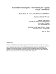
TAP System Controller #1 – The MicroTAP Controller
Back Panel Hook-up
Power:
Plug the supplied 9Vdc power adapter into either of the 2 power jacks.
Data Out:
Plug one end of the supplied Toslink Cables into one of the Data OUT jacks. Then plug the other end
of each Toslink cable into the “Data In” jack on top of each Bent Unit (located at the amplifier inputs).
Alternately – if the system layout suits it better – plug a single fiber optic cable into Data Out on the MicroTAP
Controller and plug the end into the “Data IN” on the closest Bent Unit. Then route the second cable from that
Bent Unit's “Data OUT” jack on to the “Data IN” jack on the second Bent Unit. This is an example of a what is
called a 'daisy chained' connection.
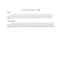
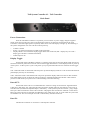
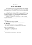
TAP System Controller #2 – TRIK
The TRIK has a few additional buttons and a rotary level knob but it does not 'sound better' than the
MicroTAP Controller. It's the “what the heck is that?” System Controller option.
Size: 17”W x 2”H x 5”D
Buttons (from the left side)
TAPE:
Pressing this button toggles the tape output on and off. This only is used in a system with a 6 input Bent
Unit – since that is the only Bent Unit with a tape output. When the Tape Out is on a blue led behind the frosted
rod in the front of the trick will light up.
Prev Source:
Pressing this button lowers the source number by 1. If the source selected is already source 1 then the
source selected wraps around to source number 6. The source is displayed via the led behind the frosted bar
across the front of the unit.
Buffer Mode:
Only of use in systems using the Bent TAP-X Autoformer Pre-amp (configured as a Bent Unit) run
from the TRIK Controller. In that system this button toggles between Buffer and 100% passive mode – the input
led will turn orange to indicate buffer mode is on. See the TAP-X Instruction Manual for a full description of the
buffer mode.
Next Source:
Pressing this button raises the source number by 1. If the source selected is already source 6 then the
source selected wraps around to source number 1. The source is displayed via the led behind the frosted bar
across the front of the unit.
TAP System Controller #2 – TRIK
Mute:
If the mute button is pressed the frosted display ball will turn off and the blue mute led (behind the
frosted rod in the front panel) will turn on and the system will mute. Pressing the button again (or pressing a
volume up or down button) will un-mute the system and the frosted display ball will return to showing the
volume level.
Volume Knob:
On the far right of the TRIK is the level control knob. Spinning it will adjust the volume up and down.
The volume is 'displayed' via the frosted ball on the far left of the unit. The ball will be off for mute then glow
blue for lower volumes and then continuously change color to green,orange, and finally red red as the volume is
raised higher and higher. It's easy to see at a glance from anywhere in the listening room what the current level is
set to.
TAP System Controller #2 - TRIK
Back Panel Connections
Power (9VDC):
Plug the supplied 9VDC power supply into the TRIK controller power input. The display will light up.
The following is the system configuration of a new TRIK on initial power up:
–
–
–
–
Volume is muted
Source 1 is selected in Normal (no buffer) mode (green led)
Display Mode is set to match the display toggle on the back of the unit (ON = display stays on / OFF =
display goes off after a command is finished).
TAPE Output is off
Display Toggle:
On the back of the TRIK is a display toggle switch. Since the display mode can also be selected via
remote control all this toggle switch does is set the display mode on power up of the system - so after a power
cycle it will power up in your preferred mode. The two selections for the toggle are:
'ON' - When this mode is selected the TRIK will power up with the display mode set to ON. In this mode the
front panel display will stay on continuously.
'OFF' - When this mode is selected the TRIK will power up with the display mode set to OFF. In this mode the
front panel display will be on while the TRIK is executing a command and then turn off after a short timeout
period. Use this mode if you prefer to have a dark listening room while listening.
Data OUT:
On the back of the TRIK are 3 Toslink Data OUT connectors. Plug one end of each supplied Toslink
Cable into any Data OUT jack. Then plug the other end of each Toslink cable into the “Data In” jack on top of
each Bent Unit (located at the amplifier inputs). Alternately – if the system layout suits it better – plug a single
fiber optic cable into Data Out on the TRIK and plug the other end into the “Data IN” on the closest Bent Unit.
Then route the second cable from that Bent Unit's “Data OUT” jack on to the “Data IN” jack on the second Bent
Unit. This is an example of a what is called a 'daisy chained' connection.
TAP System Controller #2 - TRIK
Back Panel Connections
Bypass:
This small push button programs an input to lock the volume level – used to set an input to HT Bypass
mode and always jump to a particular volume level when that input is selected. This is only used in systems
using 6 input Bent Units. If you only have a single input system then it is unlikely you'll want to program it to
always stay on one volume level!
Pressing this button programs the currently selected input to lock to the current volume and pressing the button
again 'unlocks' the volume setting. The status of each input is shown via that inputs led:
For normal (unlocked) mode the led is green (or orange if the main path buffer for that
input is set to is active mode).
For lock (or bypass) mode the led will turn red.
The HT mode of each input is saved in non volatile memory so even after a power outage this
programming is stored inside the TRIK.
Most often this is used to program an input connected to a home theater processor so that the input will
jump to level 61 (unity gain) when that input is selected. When a non HT input is once again selected the level
jumps back to the prior volume level setting. A level 61 setting connects the input jack directly to the output
jack. An alternate level can also be used if you'd like. Each time that source is selected the level will jump to the
programmed level and you use the HT processors level control to set the volume - which also controls the other
channels such as rear channels, etc... If your HT processor already had it's levels set for the same amplifiers
directly connected to the HT Processor then using level 61 (unity gain) on the TRIK will maintain proper
surround channel vs main channel levels. If you are installing the processor new or making other changes in the
system then you should set the TRIK to an HT mode for that processor input BEFORE you set your surround
levels. That way the system levels will be correct each time that input is selected.
The volume could simply be set manually to the same level each time you use that HT input. The HT
button is simply a handy way to make the level jump automatically to the same volume each time that input is
selected and more importantly to automatically return to the previous level setting when a non HT input is again
selected.
NOTE:
In some systems switching to an unused input will cause a small amount of hum at the speakers. This is
because with no input connected the signal path is 'hanging in the breeze' picking up whatever noise is floating
by. For unused inputs HT mode can be engaged and set to volume level 1. Then when selected the level is so low
that there will be no hum.
TAP System Controller #3 - TAP Controller
This controller can be used where more front panel functionality than the MicroTAP Controller is
required. It can be configured for special applications to also act as a 6 input switch center to perform source
selection in the TAP Modular system. .
Front Panel
Size: 17”W x 2”H x 10”D
Display Button / Led:
Each button press toggles between the 2 display modes. When the led is on (display mode on) the
display stays on continuously. When the led is off (display mode off ) the display will be on while you are using
the pre-amp / remote functions and then after a short timeout the display turns off for dark listening. The Red
button on the upper left corner of the remote also toggles the display mode.
TAPE Button / Led:
The TAPE button toggles between TAPE Output On and TAPE Output off. See TAPE output
connection details on the 6 input Bent Unit description below for information on how the TAPE Output
functions.
Mute Button / Led:
This button toggles between mute and normal volume modes. When the mute led is on the system is
muted. The mute button on the remote also toggles mute mode. Adjusting volume via the remote or the volume
knob resets the TAP to not muted.
Left Channel Volume Display:
This numeric led displays the current volume of the left channel.
- In Mute Mode the display reads double dashes “--”
- The lowest volume level (level 1) is -60db attenuation
- Unity Gain ( 0db attenuation) is at level 61
Volume Knob:
Not much to say - it's a volume knob.
Right Channel Volume Display:
This numeric led displays the current volume of the right channel.
- In Mute Mode the display reads double dashes “--”
- The lowest volume level (level 1) is -60db attenuation
- Unity Gain ( 0db attenuation) is at level 61
TAP System Controller #3 – TAP Controller
TAP Controller – Front Panel (continued)
Just to the right of the Right channel numeric display are the source select functions. These are only of
interest when using a 6 Input Bent Unit in the system . If you have only single input Bent Units you are still
welcome to press these buttons but it will have no affect on the system.
Source Down Button:
Each button press changes the selected source to the next lower source. If this button is pressed while
source 1 is selected the source wraps around to source 6. The current source is indicated via a row of leds just
above the source buttons.
Buffer Mode:
Only of use in systems using the Bent TAP-X Autoformer Pre-amp (configured as a Bent Unit) run
from the TAP Controller. In that system this button toggles between Buffer and 100% passive mode – the input
led will turn orange to indicate buffer mode is on. See the TAP-X Instruction Manual for a full description of
the buffer mode.
Source Up Button:
Each button press changes the selected source to the next higher source. If this button is pressed while
source 6 is selected the source wraps around to source 1. The current source is indicated via a row of leds just
above the source buttons.
Source LEDs:
Above the source/phase buttons are a row of 6 leds. They indicate the selected source number. The left
most led is source 1 and the right most led is source 6.
Green = Normal (Buffer Mode Off)
Orange = Buffer Mode On
Red = HT bypass (lock to volume 'xx').
TAP System Controller #3 – TAP Controller
Back Panel
Power Connection:
Once the TAP Main Controller is in position you can connect it's power supply. Plug the supplied
9VDC power unit into the power jack on the back panel. There is no electrical connection from the TAP
Controller to the audio signal path so any handy outlet can be used. The display will light up. The following is
the system configuration of a new TAP-X on initial power up:
–
–
–
–
Volume is muted
Source 1 is selected in Normal (no buffer) mode (green led)
Display Mode is set to match the display toggle on the back of the unit (ON = display stays on / OFF =
display goes off after a command is finished).
TAPE Output is off
Display Toggle:
On the back of the TAP Main Controller is a display toggle switch. Since the display mode can also be
selected via the front panel and via remote control all this toggle switch does is set the display mode on power up
of the system - so after a power cycle it will power up in your preferred mode. The two selections for the toggle
are:
'ON' - When this mode is selected the TAP will power up with the display mode set to ON. In this mode the front
panel display will stay on continuously.
'OFF' - When this mode is selected the TAP will power up with the display mode set to OFF. In this mode the
front panel display will be on while the TAP is executing a command and then turn off after a short timeout
period. Use this mode if you prefer to have a dark listening room while listening.
Data OUT:
On the back of the TAP are 3 Toslink Data OUT connectors. Plug one end of each supplied Toslink
Cable into a Data OUT jack. Then plug the other end of each Toslink cable into the “Data In” jack on top of
each Bent Unit (located at the amplifier inputs). Alternately – if the system layout suits it better – plug a single
fiber optic cable into Data Out on the TAP Controller and plug the other end into the “Data IN” on the closest
Bent Unit. Then route the second cable from that Bent Unit's “Data OUT” jack on to the “Data IN” jack on the
second Bent Unit. This is an example of a what is called a 'daisy chained' connection.
Data IN:
The Data IN connection is not used on a TAP System Controller.
TAP System Controller #3 – TAP Controller
Back Panel - Continued
Bypass - Home Theater Bypass Button:
This small push button programs an input to lock the volume level – used to set an input to HT Bypass
mode and always jump to a particular volume level when that input is selected. This is only used in systems
using 6 Input Bent Units. If you only have one input it is unlikely you'll want to program it to always stay on
one volume level!
Pressing this button programs the currently selected input to lock to the current volume and pressing the button
again 'unlocks' the volume setting. The status of each input is shown via that inputs led:
For normal (unlocked) mode the led is green (or orange if the main path buffer for that
input is set to is active mode).
For lock (or bypass) mode the led will turn red.
The HT mode of each input is saved in non volatile memory so even after a power outage this
programming is stored inside the TAP Controller.
Most often this is used to program an input connected to a home theater processor so that the input will
jump to level 61 (unity gain) when that input is selected. As a non HT input is once again selected the level
jumps back to the prior level setting. A level 61 setting connects the input jack directly to the output jack. An
alternate level can also be used if you'd like. Each time that source is selected the level will jump to the
programmed level and you use the HT processors level control to set the volume - which also controls the other
channels such as rear channels, etc... If your HT processor already had it's levels set for the same amplifiers
directly connected to the HT Processor then using level 61 (unity gain) on the TAP Controller will maintain
proper surround channel vs main channel levels. If you are installing the processor new or making other changes
in the system then you should set the TAP to an HT mode for that processor input BEFORE you set your
surround levels. That way the system levels will be correct each time that input is selected.
The volume could simply be set manually to the same level each time you use that input. The HT button
is simply a handy way to make the level jump automatically to the same volume each time that input is selected
and more importantly to automatically return to the previous level setting when a non HT input is again selected.
NOTE:
In some systems switching to an unused input will cause a small amount of hum at the speakers. This is
because with no input connected the signal path is 'hanging in the breeze' picking up whatever noise is floating
by. For unused inputs HT mode can be engaged and set to volume level 1. Then when selected the level is so low
that there will be no hum.
Bent Units
Any of our attenuator options can be made into mono or stereo Bent Units – including the Autoformer
attenuators. Autoformer systems do NOT have to be located close to amp inputs like resistor passive pre-amps
do and so those are made up on a special order basis only – to suit particular system needs.
Here we'll describe the most common choices of Bent Units. These are:
1- Mono RCA Bent Unit
2- Mono XLR Bent Unit
3- Single Input Stereo Bent Unit
4- Six Input Stereo Bent Unit
In all cases the Bent Unit(s) should be located at the amplifier Input. The Mono Bent Units have a
short cable to plug into the amp input. If using a stereo Bent Unit with output RCA jacks then use a short (0.5M
or less) cable to connect the output of the Bent Unit to the Amp Inputs. All Bent Units use the same high quality
Hybrid Attenuator Boards from Bent Audio.
How To Select Bent Units Needed In Your System
If your system has only one source and you use monoblock amps then choose one pair of the Mono
Bent Units. If you use XLR connections at both your source and your amplifier. Then use the XLR (fully
Balanced) Bent Units.
. If your system has only one source and you use a stereo amp with RCA type connections you may
choose either the Mono or Single Input Stereo Bent Units. Most of the time the Mono Bent Units - with their
short integral cable - will be the best choice.
If your system has more than one input then choose the 6 Input Stereo Bent Unit.
Important Note:
Since the cost of the TAP Modular Passive Pre-amp system with a 6 Input Stereo Resistor Bent Unit
approaches the cost of a TAP-X Autoformer Pre-amp in almost all cases the TAP-X will be the best choice. The
Autoformers generally will perform better sonically than the resistor passive. Also because the Autoformer
controls are NOT required to be close to the amplifier input the TAP-X can (and is) implemented as a single box
pre-amp and is located in your system rack just like an active pre-amp would be. There are cases - such as when
putting together a complex surround system – where the 6 input Resistor Bent Unit can be a logical choice as
part of that system.
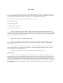
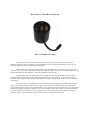
Bent Unit #1 - Mono RCA Bent Unit
Size: 3-1/2”Diam x 5” High
This is the most common Bent Unit and it was shown in the system connection example at the
beginning of this document. Designed to be plugged directly in to your amp input this Bent Unit can be run
from any of the TAP Controller Options described above.
Inside this Bent Unit is the high quality Bent Audio Hybrid Resistor Attenuator circuit. This circuit
combines a very short clean signal path of a shunt type control but has a much more controlled impedance range
than a traditional shunt type attenuator. The input impedance is 9K nominal.
The Mono Bent Units are shipped as a pair including one left (white RCA) and one right (red RCA).
For multichannel systems they can be configured as neither right or left channels – ie. for a center channel
attenuator. This balance function setting can be changed via jumper settings inside the Bent Unit if you need to
in the future.
The output cable is an unshielded version of the cable used on the highly regarded MU Moving Coil
Step-up. This custom cable is made from OCC copper with a natural wool damping wrap and is of MUCH
higher quality than the internal wiring found inside even very high end pre-amps. Think of it as very high quality
internal wiring that you happen to be able to see. The second RCA output jack on the top of the Bent Unit may
be used to connect to your amp via your own cable but this cable must be kept 0.5M or shorter in length for
optimum operation. This second RCA jack can also connect to a nearby subwoofer input.
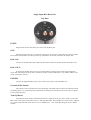
Single Input RCA Bent Unit
Top Plate
INPUT:
Plug the Interconnect cable from your source into this RCA jack.
OUT:
Plug the integral cable into your amps RCA input jack. If you have a subwoofer then connect an RCA
Interconnect cable from the OUT RCA jack on top of the Bent Unit into the subwoofer RCA Input Jack.
DATA IN:
Connect the Toslink Fiber Optic cable from the TAP Controller to the Data In jack on the Bent Unit.
DATA OUT:
If connecting the Bent Unit's from one to another (Daisy Chaining) then connect the Toslink Fiber
Optic cable from the DATA OUT jack to the DATA IN jack on the next Bent Unit. Any number of Bent Units
can be connected in this way.
POWER:
Connect the supplied 9VDC power unit to either Power Jack on top of the Bent Unit.
Ground (GND) Switch:
This switch is used to optimize the system grounding. The GND selects between two alternate internal
grounding options. Try each setting and combinations of settings with other Bent Units in the system to get the
system completely quiet.
Trim Up/Down:
These buttons can be used in multichannel systems to adjust the level up or down relative to the other
Bent Units in the system. Each button press is a 1db step adjustment. The leds light up to show if trim is adjusted
up or down. With both leds off the trim is set to it's middle point – this will be the setting for all two channel
systems.
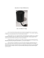
Bent Unit #2 - Mono XLR Bent Unit
Size: 3-1/2”Diam x 5” High
This is a fully balanced (XLR type) Bent Unit. Designed to be plugged directly in to your amp input
this Bent Unit can be run from any of the TAP Controller Options described above. This would be a good fit for
a system using a single fully balanced source and a fully balanced amplifier.
Inside this Bent Unit is a pair of high quality Bent Audio Hybrid Resistor Attenuator circuit – making it
a true balanced attenuator. This circuit combines a very short clean signal path of a shunt type control but has a
much more controlled impedance range than a traditional shunt type attenuator. The input impedance is 9K
nominal from each side of the connection (pin2 or pin3) to ground (pin1).
The Mono Bent Units are shipped as a pair including one left and one right. For multichannel systems
they can be configured as neither right or left channels – ie. for a center channel attenuator. This balance setting
can be changed via jumper settings inside the Bent Unit if you need to in the future.
The output cable is an unshielded version of the cable used on the highly regarded MU Moving Coil
Step-up. This custom cable is made from OCC copper with a natural wool damping wrap and is of MUCH
higher quality than the internal wiring found inside even very high end pre-amps. Think of it as very high quality
internal wiring that you happen to be able to see. The second RCA output jack on the top of the Bent Unit may
be used to connect to your amp via your own cable but this cable must be kept shorter than 0.5M in length for
optimum operation.
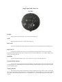
Single Input XLR Bent Unit
Top Plate
INPUT:
Plug the Interconnect cable from your source into this XLR jack.
OUT:
Plug the integral cable into your amps XLR input jack.
DATA IN:
Connect the Toslink Fiber Optic cable from the TAP Controller to the Data In jack on the Bent Unit.
DATA OUT:
If connecting the Bent Unit's from one to another (Daisy Chaining) then connect the Toslink Fiber
Optic cable from the DATA OUT jack to the DATA IN jack on the next Bent Unit. Any number of Bent Units
can be connected in this way.
POWER:
Connect the supplied 9VDC power unit to either Power Jack on top of the Bent Unit.
Ground (GND) Switch:
This switch is used to optimize the system grounding. The GND selects between two alternate internal
grounding options. Try each setting and combinations of settings with other Bent Units in the system to get the
system completely quiet.
Trim Up/Down:
These buttons can be used in multichannel systems to adjust the level up or down relative to the other
Bent Units in the system. Each button press is a 1db step adjustment. The leds light up to show if trim is adjusted
up or down. With both leds off the trim is set to it's middle point – this will be the setting for all two channel
systems.
Single Input Stereo Bent Unit
Front Panel
Size: 17”W x 2”H x 10”D
Inside this Bent Unit is a pair of the high quality Bent Audio Hybrid Resistor Attenuator circuit boards.
It combines a very short clean signal path of a shunt type control but has a much more controlled impedance
range than a traditional shunt type attenuator. The input impedance is 9K nominal.
The Stereo Bent Unit is shipped with the channels set for right (Red RCA) and left (White RCA)
balance function. For multichannel systems they can be configured as neither right or left channels – ie. for a
center channel attenuator. This balance setting can be easily changed via jumper settings inside the Bent Unit if
you need to in the future.
Trim Up/Down:
These buttons can be used in multichannel systems to adjust the level up or down relative to the other
Bent Units in the system. Each button press is a 1db step adjustment. The leds light up to show if trim is adjusted
up or down. With both leds off the trim is not used – this will be the setting for all two channel systems.
Single Input Stereo Bent Unit
Back Panel
IN:
Connect your source component to this RCA input jack. The upper (red) RCA input is for the right
channel and the lower (white) RCA input is for the left channel connection. Inputs are staggered to allow easier
access to tighten the cable's RCA connectors.
Out 1:
Connect the Output #1 RCA jack to your main amps RCA Inputs. Use cables 0.5M or shorter to make
this connection.
Out 2:
If you have a subwoofer or if you bi-amp connect Output #2 to the input RCA jack on the subwoofer or
on the bass amp.
Power:
Once the Bent Unit is in position and wired up you can connect it's power supply. Plug the supplied
9VDC power unit into the power jack on the back of the Bent Unit.
Expansion Port IN:
Connect the Toslink Fiber Optic cable from your TAP Controller to this Toslink Input connector.
Expansion Port OUT:
These 3 Toslink Fiber Optic connectors can be connected via Toslink cable to Input Toslink connectors
on other Bent Units in the system.
Display Toggle:
The Display Toggle is not used on Bent Units – it is only used on TAP Controllers.
Bypass Button:
The HT (home theater) Bypass Button is not used on Bent Units – it is only used on TAP Controllers.
6 Input Stereo Bent Unit
Front Panel
Size: 17”W x 2”H x 10”D
Inside this Bent Unit is a pair of high quality Bent Audio Hybrid Resistor Attenuator circuit boards.
This circuit combines a very short clean signal path of a shunt type control but has a much more controlled
impedance range than a traditional shunt type attenuator. The input impedance is 9K nominal.
The Stereo Bent Unit is shipped with the channels set for right (Red RCA) and left (White RCA)
balance function. For multichannel systems they can be configured as neither right or left channels – ie. for a
center channel attenuator. This balance setting can be changed via jumper settings inside the Bent Unit if you
need to in the future.
Trim Up/Down:
These buttons can be used in multichannel systems to adjust the level up or down relative to the other
Bent Units in the system. Each button press is a 1db step adjustment. The leds light up to show the trim is
adjusted up or down. With both leds off the trim is not used – this will be the setting for all two channel systems.
6 Input Stereo Bent Unit
Back Panel
Inputs 1 to 6:
Connect your source components to these RCA input jacks. If you use less than 6 inputs then plug them
into adjacent inputs starting at input number 1. The upper (red) RCA inputs are for the right channel and the
lower (white) RCA inputs are for the left channel connections. Inputs are staggered to allow easier access to
tighten the cable's RCA connectors.
Out 1:
Connect the Output #1 RCA jack to your main amps RCA Inputs. Use cables 0.5M or shorter to make
this connection.
Out 2:
If you have a subwoofer or you bi-amp connect Output #2 to the input RCA jack on the subwoofer or
on the bass amp.
Tape Output:
Not Often used in a Bent Unit system. If your Bent Unit is in your main rack along with your
amplifier(s) then the Tape Out jacks can be used to feed a Tape Deck or CDR's input jack. These output jacks
are switched on and off via a button on the front panel of the TAP System Controller (the TAPE button - as you
might expect). When the TAPE function is on the output jacks are connected straight from the currently selected
input jack - at unity gain just as if you plugged your source directly into your recorder.
Note:
This is a bit different than a traditional 'tape loop'. We have chosen this method over a tape loop
because the traditional tape loop introduces additional contacts to the main signal path all the time - even when
the tape function is not used. We prefer to keep the main signal path as clean as we can and only add features
'around' that main signal path.
These switched tape outputs can also be used to feed a headphone amp with it's own built in volume
control.
Power:
Once the Bent Unit is in position and wired up you can connect it's power supply. Plug the supplied
9VDC power unit into the power jack on the back of the Bent Unit.
Display Toggle:
The Display Toggle is not used on Bent Units – it is only used on TAP Controllers.
Bypass Button:
The HT Bypass Button is not used on Bent Units – it is only used on TAP Controllers.
TAP Modular Pre-amp Features and Specifications
Because all Bent Units share the same circuits for attenuation the specifications below apply to all
models.
Features:
* Continuous 1db Level Steps from -60 to +0db (unity gain)
* Remote Control of Level, Balance, Input Select, Buffer Mode, Mute, and Display
* Front Panel Control of Level, Input Select, Buffer Mode, Mute, TAPE, and Display
* Buffered and Switched TAPE Output (6 input version only)
* Any Input(s) can be programmed as an HT Input via a simple back panel button press
* Six input Bent Units = 6 RCA Inputs + Dual RCA outputs.
* One input Bent Unit = 1 RCA In + Dual RCA outputs
* Custom Remote Control Handset
* Display Dark setting for HT or dark listening
* Bent Units have trim up / trim down buttons for each channel
Performance:
* Bent Units located at the amp inputs – the only place for a resistor passive to be located!
* Bent Audio Hybrid Resistor Attenuator Board.
* 'Teflon like' Arlon PCB Material used for Signal Path Circuit Boards
* Extreme quality relays rated for billions of operations
* Modular Design for minimum internal wiring keeping the signal path VERY clean
* Expansion modules connect via fiber optic cables - no chance of ground loops
* Entire Control System enters sleep mode after each command - NO clock noise
Endurance:
* A Minimum of Mechanical Parts - Maintenance free operation
* All switching via sealed relays rated for billions of operations
* Optical Encoder Level Control rated for millions of operations
* Optional Fiber Optic Expansion ports to add unlimited additional channels
Resistor Pre-amp Specifications:
* Bandwidth: Below 10 Hz to over 100 KHz ( +/- 1db)
* Right Channel to Left Channel Level Matching: Closer than +/-.1dB
* THD: < 0.01%
* Step Size: 1db (Mute / -60dB to +0db)
* Maximum Input Level: > 10V RMS
* Maximum Channels: Unlimited
* Inputs: 1 RCA or 6 RCA (depending on Bent Units chosen)
* Outputs: 2 RCA
* TAPE Outputs: 1 RCA (6 input version only)
* HT Bypass Inputs: Any of the 6 inputs programmed as HT via button press