1
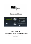
2m DISCOVERY
LINEAR AMPLIFIER
(GS – 31)
Operating Manual
WiMo Antennen und Elektronik GmbH
Am Gäxwald 14, D-76863 Herxheim Tel. (07276) 96680 FAX 6978
http://www.wimo.com
e-mail: [email protected]
INDEX
1.
2.
3.
4.
5.
Specifications
Introduction
Installation
Operating Controls
Operation
CAUTION
There are dangerously high voltages inside the amplifier when the power is
switched on. DO NOT remove the covers unless the power has been disconnected
and sufficient time has elapsed for the capacitors to discharge.
NOTE
The 2m Discovery is capable of a greater power than the CW rating shown in the
specifications. In order to achieve the stated PEP output, the amplifier must be
capable of operating CW at the same level for short periods. Do not try to operate the
amplifier at greater than the recommended level.
If the amplifier is operated for long periods at levels greater than the recommended
ones, then damage may occur. This applies particularly to the GS 31 valve, so great
care should be taken not to exceed 1Amp plate current or to drive with more than
100W continuous wave drive. Also, care should be taken not to exceed 1.5 : 1 SWR.
(1)
1. SPECIFICATIONS
Function………………….The 2m Discovery is a desk top linear RF amplifier with a
nominal output of 1000W covering the range 144-146MHz for
amateur radio use.
Type of emission…………………………………………………SSB/FM/CW/RTTY
Dimensions………………………………….……14in wide x 9.75in high x 17in deep
360mm x 250mm x 430mm
Weight……………………………………………………………………………..25kg
Output power…………………………………...…………………….1000W CW/SSB
Gain……………………………………………...………………………12dB nominal
Power requirements………………………………..………230V AC at 15A, 50/60Hz
Duty cycle………………………………………Full O/P with normal amateur service
Cooling………………………………..……………………….……Forced air cooling
Frequency coverage………………………..……………………………144-146 MHz
Input impedance……………………………..…………50 Ohms with tuned I/P circuit
Valve……………………………………….………………………single GS 31 triode
Harmonics………………………………….…………3rd harmonic: better than –45dB
Plate voltage……………………………………..……………………SSB: 2800V DC
Cabinet……………………….……………chassis – Zintec steel, covers – aluminium
RF compartment – aluchromed aluminium
Antenna relay…………24VDC antenna relays automatically transfer the driver to the
antenna when in STBY or OFF. Standard in-built are coaxial
O/P relay and short throw I/P relay.
The amplifier requires a relay contact in the driver to key the
amplifier.
Metering………………………… ……………Plate current, Grid current and RF O/P
Protection…………………………
…………..All power circuits protected by fuses
Grid protection circuit
(2)
2. INTRODUCTION
The 2m Discovery is a high quality linear amplifier which is designed around a GS 31
medium mu triode in grounded grid configuration. The amplifier uses a ¼ wave stripline in the output circuit and a tuned input circuit. The amplifier is forced air cooled to
give you the ability to operate at full output power for as long as you wish. The
recommended maximum drive is 100Watts.
The GS 31 must be allowed to warm up properly hence a 2 min. start up timer is
fitted. When the amplifier is switched on, the WAIT light will come on. After the time
has elapsed the WAIT light will go out allowing you to operate the PTT.
It is recommended that you use a Bird (or equivalent) power meter capable of
measuring 1500W at the correct frequency.
Please read the instructions carefully before operating the equipment. RF amplifiers at
this power level and frequency can be easily damaged by improper use. Please follow
the precautions on page 1 of this manual.
The Discovery is fully self-contained and has three separate voltages:1. HIGH VOLTAGE which is 2800V, the main voltage applied to the valve
anode.
2. HEATER SUPPLY which is 13V at 3A.
3. CONTROL VOLTAGE which is 12V used for the LED control condition
of the amplifier, 24V for pulling in the Tx/Rx relays.
(3)
3. INSTALLATION
SETTING UP
a) Unpack the amplifier and check that it is undamaged. The carton should also
contain a power cable, operating manual, phono plug (for relay switching
lead) and spare fuse. Please retain the packing and box should it be necessary
to ship it or move it to another location.
b) Ensure you have a reasonable airflow around the site you have chosen to
install your amplifier. Do not enclose the cabinet or restrict the airflow in any
way. Try to avoid extremes of heat, humidity or dust in order to give many
hours of trouble-free operation.
c) Ensure ALL connectors to be used by yourself are of a sufficient electrical
standard to carry the higher RF output generated by the amplifier. To properly
tune the amplifier a high quality Wattmeter (e.g. Bird thruline) should be used
to measure the output and, if possible, a similar meter between the driver and
the amplifier to correctly measure the input.
d) NEVER attempt to operate the amplifier without first connecting an antenna
or 50Ohm dummy load. Check the SWR of the antenna with the amplifier in
the OFF or STBY position and do not operate the amplifier if the SWR is
greater than 2 : 1.
e) Check that the front panel switches are in the STBY and OFF positions.
CONNECTIONS
a) POWER CABLE. The amplifier is supplied with a 3-wire Mains cable
terminated in an IEC connector to go into the socket on the rear panel. The
other end is left free for you to connect whichever plug is suitable for your
electricity supply. The supply must be 230VAC, single phase, 50/60Hz.
b) OUTPUT COAX. Any good quality 50 Ohm coax capable of carrying up to
1500W at 144MHz is suitable. This needs an N-type connector to go on to the
amplifier and whatever connector is required for your wattmeter.
c) INPUT COAX. Good quality 50 Ohm coax with an N-type connector to the
amplifier and a connector of your choice for your driver.
d) RELAY SWITCHING LEAD. A phono plug is supplied for you to make a
lead to go into the PTT socket on the rear of the amplifier and connect to the
antenna relay on your driver. This cable sends the keying signal from your
driver to switch the amplifier to transmit. Do not apply any voltage to the
amplifiers relay control as it has its own in-built power supply.
(4)
4. OPERATING CONTROLS
FRONT PANEL CONTROLS
ON/OFF SWITCH…………………………………………....Mains power on and off
STBY/TX……………………………………….…………Amplifier standby / operate
PLATE METER……………………..0 – 1.5A, monitors the plate current of the valve
GRID METER…………………………...0 – 400mA, monitors the grid current which
should not rise above 300mA
GRID / RF OUT…………………..switches the grid meter to monitor relative RF O/P
(LOAD CONTROL……………………………..Adjusts the loading of the strip-line)
Internally preset – can be adjusted with a screwdriver through hole in front panel
TUNE CONTROL…………………………...…….Adjusts the tuning of the strip-line
POWER LED………………………………....Shows that the amplifier is switched on
WAIT LED………………………………..Lit until the valve has warmed up and then
goes out when the amplifier is ready to use
GRID TRIP LED………………….……Indicates grid current has exceeded safe level
TX LED…………………………………………Shows when the amplifier is ON AIR
(5)
REAR PANEL
FUSE HOLDER…………………………………………………1.25” (30mm)
10A
MAINS……………………………………..IEC connector for mains cable, 230VAC
TX………………………N – type connector, coaxial INPUT to amplifier from driver
ANT…………………….N – type connector, coaxial OUTPUT to antenna through a
suitable power meter
PTT…………………………………….……Phono connector for relay switching lead
WiMo Antennen und Elektronik GmbH
Am Gäxwald 14, D-76863 Herxheim Tel. (07276) 96680 FAX 6978
http://www.wimo.com
e-mail: [email protected]
(6)
5. OPERATION
SET-UP
Connect all the cables as previously described in the manual, then double-check.
When you are satisfied that everything is correct and the STBY/TX switch is on
STBY, switch the amplifier on. There is a slight delay while the soft-start operates,
then the POWER and WAIT lights should be on. After approximately 2 minutes the
WAIT light should go out, indicating that the valve has warmed up and is ready for
operation. Now put the STBY switch to TX, which puts it into the operate mode. With
no RF drive applied, key the amplifier and check that the Plate meter shows a
standing current of about 80 – 100 mA. The green TX LED will be on when the
amplifier is keyed.
TUNE-UP
Now set your driver to about 30W output, in either CW or FM mode, and using the
two dials tune for maximum output on your power meter. This should indicate about
400W output. The amplifier will give about 1000W RMS when 80W of drive is now
applied with very slight adjustments being necessary.
In the tune mode with 600W O/P, the plate meter should rise to about half scale.
CAUTION. Maximum grid current should NEVER exceed 300mA.
The amplifier is now ready for operation.
OPERATION
The mode of operation, SSB or CW, can now be selected and operate as normal.
When the amplifier is in the STBY position the RF goes straight through from the
transceiver to the antenna, and when it is in the TX position the amplifier comes into
operation.
To key the amplifier, an earth on transmit is required from the transceiver (relay) to
the PTT socket on the back of the amplifier. When the transceiver and amplifier are
keyed, the green TX LED indicator on the front panel is lit.
During operation, keep a careful eye on the Grid meter making sure it does not exceed
300mA.
GRID PROTECTION
There is grid protection fitted to this model of 2m Discovery. If the grid current
exceeds the recommended maximum level the yellow LED will come on and the PTT
will be disabled. As the maximum level is approached the LED will flicker and an
audible clicking will be heard.
Investigate the reason for the high grid current and rectify it. Possible causes are that
there is a fault on the aerial or that the amplifier has been overdriven.
(7)
To reset the amplifier, put the STBY/TX switch to STBY then back to TX. The LED
should now have gone out and the amplifier is able to be keyed once more. Tune the
amplifier correctly to achieve maximum output with minimum grid current.
WiMo Antennen und Elektronik GmbH
Am Gäxwald 14, D-76863 Herxheim Tel. (07276) 96680 FAX 6978
http://www.wimo.com
e-mail: [email protected]
(8)
OPERATING PRECAUTIONS
To ensure safe and reliable operation please regard the following precautions:HIGH VOLTAGES CAN BE LETHAL. Never try to operate your amplifier with the
covers removed. If it is necessary to work inside the cabinet, always disconnect the
Mains supply and allow the capacitors to discharge fully.
Never operate the amplifier into a load or antenna with an SWR greater than 2 : 1.
Always tune the amplifier for resonance using low drive at the operating frequency.
The components in the amplifier are designed to be used within the parameters of the
specifications on page 2 of this manual. Excessive drive giving output in excess of
these specifications will shorten valve life and could affect the reliability of other
components.
WiMo Antennen und Elektronik GmbH
Am Gäxwald 14, D-76863 Herxheim Tel. (07276) 96680 FAX 6978
http://www.wimo.com
e-mail: [email protected]
(9)
WARRANTY
Linear Amp UK Ltd warrants to the original purchaser that this product
shall be free from defects in material or workmanship for 12 months from
the date of the original purchase. Valves are excluded from this warranty.
Notification should be given as soon as possible after discovering a
possible defect. Carriage charges for any parts or units submitted for
replacement or repair under this warranty must be paid by the purchaser.
Correct maintenance, repair and use are important to insure proper
performance from this product. Carefully read the operating manual. This
warranty does not apply to any defect Linear Amp UK Ltd determines is
caused by (1) improper maintenance or repair, including the installation
of parts or accessories that do not conform to the quality and specification
of the original parts; (2) misuse, abuse, neglect or improper installation;
(3) accidental or intentional damage; (4) acts of God.
Linear Amp UK Ltd is not responsible for damage to other equipment or
property or any other consequential or incidental damage of any kind.
This warranty is not transferable from the original owner on sale of the
unit to another.
WiMo Antennen und Elektronik GmbH
Am Gäxwald 14, D-76863 Herxheim Tel. (07276) 96680 FAX 6978
http://www.wimo.com
e-mail: [email protected]