1
Bull ESCALA
T610, PL 400T and PL 600T
Service Guide
ORDER REFERENCE
86 A1 40KX 03
Bull ESCALA
T610, PL 400T and PL 600T
Service Guide
Hardware
May 2002
BULL CEDOC
357 AVENUE PATTON
B.P.20845
49008 ANGERS CEDEX 01
FRANCE
ORDER REFERENCE
86 A1 40KX 03
The following copyright notice protects this book under the Copyright laws of the United States of America
and other countries which prohibit such actions as, but not limited to, copying, distributing, modifying, and
making derivative works.
Copyright
Bull S.A. 1992, 2002
Printed in France
Suggestions and criticisms concerning the form, content, and presentation of
this book are invited. A form is provided at the end of this book for this purpose.
To order additional copies of this book or other Bull Technical Publications, you
are invited to use the Ordering Form also provided at the end of this book.
Trademarks and Acknowledgements
We acknowledge the right of proprietors of trademarks mentioned in this book.
AIX is a registered trademark of International Business Machines Corporation, and is being used under
licence.
UNIX is a registered trademark in the United States of America and other countries licensed exclusively through
the Open Group.
In this book, 25F/80 stands for T610, 256/F0 for
PL 400T and 256/F1 for PL 600T.
The information in this document is subject to change without notice. Groupe Bull will not be liable for errors
contained herein, or for incidental or consequential damages in connection with the use of this material.
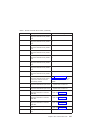
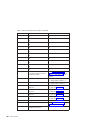
Contents
Safety Notices . . . . . . . . . . . . . . . . . . . . . . . . xi
Electrical Safety . . . . . . . . . . . . . . . . . . . . . . . xii
Laser Safety Information . . . . . . . . . . . . . . . . . . . . . xii
Laser Compliance . . . . . . . . . . . . . . . . . . . . . . xii
Data Integrity and Verification .
.
.
.
.
.
.
.
.
.
.
.
.
.
.
.
.
. xv
About This Book . . . . . . . . . . . . . . . . . . . . . . xvii
ISO 9000 . . . . . . . . . . . . . . . . . . . . . . . . . xvii
Related Publications . . . . . . . . . . . . . . . . . . . . . . xvii
Trademarks . . . . . . . . . . . . . . . . . . . . . . . . xviii
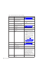
Chapter 1. Reference Information . . . . . . . . . . . . . .
Overview . . . . . . . . . . . . . . . . . . . . . . .
Bus Architecture . . . . . . . . . . . . . . . . . . . .
Microprocessor . . . . . . . . . . . . . . . . . . . .
Memory . . . . . . . . . . . . . . . . . . . . . .
Media Drives . . . . . . . . . . . . . . . . . . . . .
Internal Hard Disk Drives . . . . . . . . . . . . . . . . .
Power Supply . . . . . . . . . . . . . . . . . . . .
Keyboard . . . . . . . . . . . . . . . . . . . . . .
Mouse . . . . . . . . . . . . . . . . . . . . . . .
Operator Panel . . . . . . . . . . . . . . . . . . . .
Input/Output Ports . . . . . . . . . . . . . . . . . . .
Security Features . . . . . . . . . . . . . . . . . . .
Data Flow with One-Way Processor . . . . . . . . . . . . . .
Data Flow with Two- to Six-Way Processor . . . . . . . . . . . .
Power Flow . . . . . . . . . . . . . . . . . . . . . .
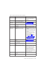
Powering Off and Powering On the System . . . . . . . . . . . .
Powering Off the System . . . . . . . . . . . . . . . . .
Powering On the System . . . . . . . . . . . . . . . . .
Powering Off and Powering On the System Using the Service Processor .
Console Strategy . . . . . . . . . . . . . . . . . . . .
Power-On Self-Test . . . . . . . . . . . . . . . . . . . .
POST Indicators . . . . . . . . . . . . . . . . . . . . .
POST Keys . . . . . . . . . . . . . . . . . . . . . .
1 Key . . . . . . . . . . . . . . . . . . . . . . .
5 Key . . . . . . . . . . . . . . . . . . . . . . .
6 Key . . . . . . . . . . . . . . . . . . . . . . .
8 Key . . . . . . . . . . . . . . . . . . . . . . .
System Unit Locations . . . . . . . . . . . . . . . . . .
Front View . . . . . . . . . . . . . . . . . . . . .
Rear View . . . . . . . . . . . . . . . . . . . . .
System Board . . . . . . . . . . . . . . . . . . . .
Operator Panel . . . . . . . . . . . . . . . . . . . .
System Memory . . . . . . . . . . . . . . . . . . . .
One-Way Processor Memory Placement Rules . . . . . . . . .
.
.
.
.
.
.
.
.
.
.
.
.
.
.
.
.
.
.
.
.
.
.
.
.
.
.
.
.
.
.
.
.
.
.
.
.
.
.
.
.
.
.
.
.
.
.
. 1
. 1
. 2
. 2
. 3
. 3
. 3
. 3
. 3
. 3
. 4
. 4
. 4
. 5
. 6
. 7
. 8
. 8
. 8
. 8
. 9
. 9
. 9
. . . 10
. . . 10
. . . 10
. . . 11
. . . 11
. . . 12
. . . 12
. . . 13
. . . 14
. . . 15
. . . 15
. . . 15
iii
Riser Card Memory Placement Rules . . . . .
Logical and Physical Locations . . . . . . . .
Physical Location Codes . . . . . . . . . .
Location Code Format . . . . . . . . . .
Multiple FRU Callout Instructions . . . . . . .
AIX Location Codes . . . . . . . . . . . .
AIX and Physical Location Code Reference Tables .
Memory Riser Card and Memory DIMM Locations .
One-Way Processor Card Memory DIMM Locations
Specifications . . . . . . . . . . . . . .
Dimensions . . . . . . . . . . . . . .
Weight . . . . . . . . . . . . . . .
Operating Environment . . . . . . . . . .
Operating Voltage . . . . . . . . . . . .
Heat Output (Maximum) . . . . . . . . . .
Acoustics . . . . . . . . . . . . . .
External AC Power Cables . . . . . . . . . .
Service Inspection Guide . . . . . . . . . .
.
.
.
.
.
.
.
.
.
.
.
.
.
.
.
.
.
.
.
.
.
.
.
.
.
.
.
.
.
.
.
.
.
.
.
.
.
.
.
.
.
.
.
.
.
.
.
.
.
.
.
.
.
.
.
.
.
.
.
.
.
.
.
.
.
.
.
.
.
.
.
.
.
.
.
.
.
.
.
.
.
.
.
.
.
.
.
.
.
.
.
.
.
.
.
.
.
.
.
.
.
.
.
.
.
.
.
.
.
.
.
.
.
.
.
.
.
.
.
.
.
.
.
.
.
.
.
.
.
.
.
.
.
.
.
.
.
.
.
.
.
.
.
.
.
.
.
.
.
.
.
.
.
.
.
.
.
.
.
.
.
.
.
.
.
.
.
.
.
.
.
.
.
.
.
.
.
.
.
.
16
16
16
16
17
18
20
22
23
29
29
30
30
30
30
31
31
31
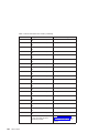
Chapter 2. Diagnostics Overview . . .
Maintenance Analysis Procedures (MAPs) .
Checkpoints . . . . . . . . . . .
FRU Isolation . . . . . . . . . .
.
.
.
.
.
.
.
.
.
.
.
.
.
.
.
.
.
.
.
.
.
.
.
.
.
.
.
.
.
.
.
.
.
.
.
.
.
.
.
.
33
33
34
35
.
.
.
.
.
.
.
.
.
.
.
.
.
.
.
.
.
.
.
.
.
.
.
.
.
.
.
.
.
.
.
.
.
.
.
.
.
.
.
.
.
.
.
.
.
.
.
.
.
.
.
.
.
.
.
.
.
.
.
.
.
.
.
.
.
.
.
.
.
.
.
.
.
.
.
.
.
.
.
.
.
.
.
.
.
.
.
.
.
.
.
.
.
.
.
.
.
.
.
.
.
.
.
.
.
.
.
.
.
.
.
.
.
.
.
.
.
.
.
.
.
.
.
.
.
.
.
.
.
.
.
.
.
.
.
.
.
.
.
.
.
.
.
.
.
.
.
.
.
.
.
.
.
.
.
.
.
.
.
.
.
.
.
.
.
.
.
.
.
.
.
.
.
.
.
.
.
.
.
.
.
.
.
.
.
.
.
.
.
.
.
.
.
.
.
.
.
.
.
.
.
.
.
.
.
.
.
.
.
.
.
.
.
.
.
.
.
.
.
.
.
.
.
.
.
.
.
.
.
.
.
.
.
.
.
.
.
.
.
.
.
.
.
.
.
.
.
.
.
.
.
.
.
.
.
.
.
.
.
.
37
37
38
39
44
44
48
48
49
49
50
50
51
51
52
53
70
72
72
72
72
73
73
73
73
73
.
.
.
.
.
.
.
.
.
.
.
.
.
.
.
.
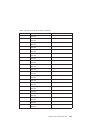
Chapter 3. Maintenance Analysis Procedures (MAPs)
Entry MAP . . . . . . . . . . . . . . .
Quick Entry MAP . . . . . . . . . . . . .
Quick Entry MAP Table of Contents . . . . . .
MAP 1020: Problem Determination . . . . . . .
Purpose of this MAP . . . . . . . . . . .
MAP 1520: Power . . . . . . . . . . . . .
Step 1520-1 . . . . . . . . . . . . . .
Step 1520-2 . . . . . . . . . . . . . .
Step 1520-3 . . . . . . . . . . . . . .
Step 1520-4 . . . . . . . . . . . . . .
Step 1520-5 . . . . . . . . . . . . . .
Step 1520-6 . . . . . . . . . . . . . .
Step 1520-7 . . . . . . . . . . . . . .
MAP 1540: Minimum Configuration . . . . . . .
Purpose of this MAP . . . . . . . . . . .
SSA Maintenance Analysis Procedures (MAPs) . . .
Using SSA MAPs . . . . . . . . . . . .
MAP 2010: SSA Hot-Swap Disk Drive–Start . . . .
Step 2010-1 . . . . . . . . . . . . . .
Step 2010-2 . . . . . . . . . . . . . .
Step 2010-3 . . . . . . . . . . . . . .
Step 2010-4 . . . . . . . . . . . . . .
Step 2010-5 . . . . . . . . . . . . . .
Step 2010-6 . . . . . . . . . . . . . .
Step 2010-7 . . . . . . . . . . . . . .
iv
Service Guide
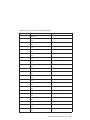
Step 2010-8 . . . .
Step 2010-9 . . . .
Step 2010-10 . . .
Step 2010-11 . . .
Step 2010-12 . . .
Step 2010-13 . . .
MAP 2323: SSA hot-swap
Step 2323-1 . . . .
Step 2323-2 . . . .
Step 2323-3 . . . .
MAP 2324: SSA hot-swap
. . . . . . . . .
. . . . . . . . .
. . . . . . . . .
. . . . . . . . .
. . . . . . . . .
. . . . . . . . .
disk drive Intermittent Link
. . . . . . . . .
. . . . . . . . .
. . . . . . . . .
disk drive RAID . . .
Chapter 4. Checkpoints . .
IPL Flow . . . . . . . .
Service Processor Checkpoints
Firmware Checkpoints . . .
Boot Problems and Concerns .
Step 1 . . . . . . .
Step 2 . . . . . . .
Step 3 . . . . . . .
Step 4 . . . . . . .
Step 5 . . . . . . .
.
.
.
.
.
.
.
.
.
.
.
.
.
.
.
.
.
.
.
.
. . . .
. . . .
. . . .
. . . .
. . . .
. . . .
Verification
. . . .
. . . .
. . . .
. . . .
.
.
.
.
.
.
.
.
.
.
.
.
.
.
.
.
.
.
.
.
.
.
.
.
.
.
.
.
.
.
.
.
.
.
.
.
.
.
.
.
.
.
.
.
.
.
.
.
.
.
.
.
.
.
.
.
.
.
.
.
.
.
.
.
.
.
.
.
.
.
.
.
.
.
.
.
.
74
74
74
74
74
75
75
75
75
76
76
.
.
.
.
.
.
.
.
.
.
77
78
79
85
96
96
96
97
97
98
.
.
.
.
.
.
.
.
.
.
.
.
.
.
.
.
.
.
.
.
.
.
.
.
.
.
.
.
.
.
.
.
.
.
.
.
.
.
.
.
.
.
.
.
.
.
.
.
.
.
.
.
.
.
.
.
.
.
.
.
.
.
.
.
.
.
.
.
.
.
.
.
.
.
.
.
.
.
.
.
.
.
.
.
.
.
.
.
.
.
.
.
.
.
.
.
.
.
.
.
.
.
.
.
.
.
.
.
.
.
.
.
.
.
.
.
.
.
.
.
.
.
.
.
.
.
.
.
.
.
.
.
.
.
.
.
.
.
.
.
.
.
.
.
.
.
.
.
.
.
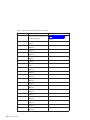
Chapter 5. Error Code to FRU Index .
Four-Character Checkpoints . . . .
Operator Panel Replacement . . . .
Replacing the Network Adapter . . .
Determining Location Code. . . . .
Checkpoint and Error Code Index . .
Performing Slow Boot . . . . . .
Confirming Initial Error Code . . . .
Memory-Related Error Codes . . .
Operator Panel Error Codes . . . .
SPCN Error Codes . . . . . . .
Firmware Error Codes . . . . . .
Service Processor Error Codes . . .
System Firmware Update Messages .
Common Firmware Error Codes. . .
Scan Log Dump Progress Codes . .
Problem Determination-Generated Error
.
.
.
.
.
.
.
.
.
.
.
.
.
.
.
.
.
.
.
.
.
.
.
.
.
.
.
.
.
.
.
.
.
.
.
.
.
.
.
.
.
.
.
.
.
.
.
.
.
.
.
.
.
.
.
.
.
.
.
.
.
.
.
.
.
.
.
.
.
.
. 99
. 99
. 99
. 99
. 99
. . . . . . . . . . . . . . . 100
. . . . . . . . . . . . . . . 101
. . . . . . . . . . . . . . . 101
. . . . . . . . . . . . . . . 102
. . . . . . . . . . . . . . . 103
. . . . . . . . . . . . . . . 104
. . . . . . . . . . . . . . . 111
. . . . . . . . . . . . . . . 132
. . . . . . . . . . . . . . . 233
. . . . . . . . . . . . . . . 233
. . . . . . . . . . . . . . . 240
Codes . . . . . . . . . . . . 241
Chapter 6. Loading the System Diagnostics In Service Mode .
Default Boot List and Service Mode Bootlist . . . . . . . .
.
.
.
.
.
.
.
.
.
.
. 243
. 244
Chapter 7. Using the Service Processor . . . .
Service Processor Menus . . . . . . . . . .
Accessing the Service Processor Menus Locally .
Accessing the Service Processor Menus Remotely
Saving and Restoring Service Processor Settings .
Menu Inactivity . . . . . . . . . . . .
.
.
.
.
.
.
.
.
.
.
.
.
.
.
.
.
.
.
.
.
.
.
.
.
.
.
.
.
.
.
.
.
.
.
.
.
245
246
246
246
246
247
Contents
v
.
.
.
.
.
.
.
.
.
.
.
.
.
.
.
.
.
.
.
.
.
.
.
.
vi
Service Guide
General User Menu . . . . . . . . . . . . . . . . . . . . .
Privileged User Menus . . . . . . . . . . . . . . . . . . . .
Main Menu. . . . . . . . . . . . . . . . . . . . . . .
Service Processor Setup Menu . . . . . . . . . . . . . . . .
Passwords . . . . . . . . . . . . . . . . . . . . . . .
System Power Control Menu . . . . . . . . . . . . . . . . .
System Information Menu . . . . . . . . . . . . . . . . . .
Memory Riser Card 1 Memory DIMM Locations for Service Processor Menus
Memory Riser Card 2 Memory DIMM Locations for Service Processor Menus
Processor Card Memory DIMM Locations for Service Processor Menus . .
Language Selection Menu . . . . . . . . . . . . . . . . .
Call-In/Call-Out Setup Menu . . . . . . . . . . . . . . . . .
Modem Configuration Menu . . . . . . . . . . . . . . . . .
Serial Port Selection Menu . . . . . . . . . . . . . . . . .
Serial Port Speed Setup Menu . . . . . . . . . . . . . . . .
Telephone Number Setup Menu . . . . . . . . . . . . . . . .
Call-Out Policy Setup Menu . . . . . . . . . . . . . . . . .
Customer Account Setup Menu . . . . . . . . . . . . . . . .
Service Processor Procedures in Service Mode . . . . . . . . . . .
Service Processor Functions . . . . . . . . . . . . . . . . . .
System Power-On Methods . . . . . . . . . . . . . . . . . .
Service Processor Reboot/Restart Recovery . . . . . . . . . . . .
Boot (IPL) Speed . . . . . . . . . . . . . . . . . . . .
Failure During Boot Process . . . . . . . . . . . . . . . . .
Failure During Normal System Operation . . . . . . . . . . . . .
Service Processor Reboot/Restart Policy Controls . . . . . . . . . .
System Firmware Updates . . . . . . . . . . . . . . . . . .
General Information on System Firmware Updates . . . . . . . . .
Determining the Level of Firmware on the System. . . . . . . . . .
Updating System Firmware From the Service Processor Menus . . . . .
Configuring and Deconfiguring Processors or Memory . . . . . . . . .
Run-Time CPU Deconfiguration (CPU Gard) . . . . . . . . . . .
Service Processor System Monitoring - Surveillance . . . . . . . . . .
System Firmware Surveillance . . . . . . . . . . . . . . . .
Operating System Surveillance . . . . . . . . . . . . . . . .
Call-Out (Call-Home) . . . . . . . . . . . . . . . . . . . .
Console Mirroring . . . . . . . . . . . . . . . . . . . . .
System Configuration . . . . . . . . . . . . . . . . . . .
Service Processor Error Log . . . . . . . . . . . . . . . . . .
LCD Progress Indicator Log . . . . . . . . . . . . . . . . . .
Service Processor Operational Phases . . . . . . . . . . . . . .
Pre-Standby Phase . . . . . . . . . . . . . . . . . . . .
Standby Phase . . . . . . . . . . . . . . . . . . . . .
Bring-Up Phase . . . . . . . . . . . . . . . . . . . . .
Run-Time Phase . . . . . . . . . . . . . . . . . . . . .
.
.
.
.
.
.
.
.
.
.
.
.
.
.
.
.
.
.
.
.
.
.
.
.
.
.
.
.
.
.
.
.
.
.
.
.
247
248
248
250
251
254
258
262
263
263
265
266
267
268
268
269
270
271
271
272
273
274
274
274
274
275
276
276
276
276
277
277
278
278
278
279
280
280
281
282
283
283
283
284
285
Chapter 8. Using System Management Services
Password Utilities . . . . . . . . . .
Display Error Log . . . . . . . . . .
Remote Initial Program Load Setup . . . .
.
.
.
.
288
287
288
289
289
.
.
.
.
.
.
.
.
.
.
.
.
.
.
.
.
.
.
.
.
.
.
.
.
.
.
.
.
.
.
.
.
.
.
.
.
.
.
.
.
.
.
.
.
.
.
.
SCSI Utilities . . . . . . . . .
Select Console . . . . . . . .
MultiBoot . . . . . . . . . .
Select Language . . . . . . . .
OK Prompt. . . . . . . . . .
Exiting System Management Services.
.
.
.
.
.
.
.
.
.
.
.
.
.
.
.
.
.
.
.
.
.
.
.
.
.
.
.
.
.
.
.
.
.
.
.
.
.
.
.
.
.
.
.
.
.
.
.
.
.
.
.
.
.
.
.
.
.
.
.
.
.
.
.
.
.
.
.
.
.
.
.
.
.
.
.
.
.
.
.
.
.
.
.
.
293
293
294
297
297
297
Chapter 9. Removal and Replacement Procedures . . . .
Handling Static-Sensitive Devices . . . . . . . . . . .
Removal and Replacement Procedures . . . . . . . . .
Covers . . . . . . . . . . . . . . . . . . . .
Removing the Covers . . . . . . . . . . . . . .
Replacing Covers . . . . . . . . . . . . . . .
Removing Processor and Memory Riser Card Cover . . . . .
Replacing Processor and Memory Riser Card Cover . . . .
Hot-Pluggable FRUs . . . . . . . . . . . . . . .
Hot-Pluggable Options . . . . . . . . . . . . . . .
Stopping the System Unit . . . . . . . . . . . . . .
Disk Drive Options . . . . . . . . . . . . . . . .
Disk Drive Slot LED Definitions . . . . . . . . . . .
Preinstallation Considerations . . . . . . . . . . .
Removing Hot-Plug SCSI Disk Drives . . . . . . . . .
Replacing Hot-Plug SCSI Disk Drives . . . . . . . . .
Configuring and Deconfiguring SCSI Hot-Swap Disk Drives .
Removing Hot-Plug SSA Disk Drives . . . . . . . . .
Replacing Hot-Plug SSA Disk Drives . . . . . . . . .
PCI Adapter Options . . . . . . . . . . . . . . .
PCI Slot LED Definitions . . . . . . . . . . . . .
Removing Adapter Cards . . . . . . . . . . . . . .
Removing a Non-Hot-Pluggable PCI Adapter . . . . . .
Removing a Hot-Pluggable PCI Adapter . . . . . . . .
Replacing Adapter Cards . . . . . . . . . . . . . .
Replacing a Non-Hot-Pluggable PCI Adapter . . . . . .
Replacing a Hot-Pluggable PCI Adapter . . . . . . . .
PCI Hot-Plug Manager Access . . . . . . . . . . . .
Accessing Hot-Plug Management Functions . . . . . . .
PCI Hot-Plug Manager Menu. . . . . . . . . . . .
Fans and Fan Fillers . . . . . . . . . . . . . . .
Removal . . . . . . . . . . . . . . . . . .
Replacement . . . . . . . . . . . . . . . . .
Power Supplies . . . . . . . . . . . . . . . . .
Removal . . . . . . . . . . . . . . . . . .
Replacement . . . . . . . . . . . . . . . . .
Installing the Redundant Power and Cooling Option . . . . .
Installing a Redundant Fan . . . . . . . . . . . .
Installing a Redundant Power Supply . . . . . . . . .
Memory Riser Card and Processor Card . . . . . . . . .
Removing a Memory Riser Card or One-Way Processor Card .
Installing a Memory Riser Card or a One-Way Processor Card
Memory and Processor Card CEC Assembly . . . . . . .
.
.
.
.
.
.
.
.
.
.
.
.
.
.
.
.
.
.
.
.
.
.
.
.
.
.
.
.
.
.
.
.
.
.
.
.
.
.
.
.
.
.
.
.
.
.
.
.
.
.
.
.
.
.
.
.
.
.
.
.
.
.
.
.
.
.
.
.
.
.
.
.
.
.
.
.
.
.
.
.
.
.
.
.
.
.
.
.
.
.
.
.
.
.
.
.
.
.
.
.
.
.
.
.
.
.
.
.
.
.
.
.
.
.
.
.
.
.
.
.
.
.
.
.
.
.
.
.
.
.
.
.
.
.
.
.
.
.
.
.
.
.
.
.
.
.
.
.
.
.
.
.
.
.
.
.
.
.
.
.
.
.
.
.
.
.
.
.
.
.
.
.
.
.
.
.
.
.
.
.
.
.
.
.
.
.
.
.
.
.
.
.
.
.
.
.
.
.
.
.
.
.
.
.
.
.
.
.
.
.
.
.
.
.
.
.
.
.
.
.
.
.
.
.
.
.
.
.
.
.
.
.
.
.
.
.
.
.
.
.
.
.
.
.
.
.
.
.
.
.
.
.
.
.
.
.
.
.
299
300
300
301
301
304
305
305
306
306
306
307
309
309
309
311
313
314
316
318
318
319
319
320
322
323
324
326
326
327
328
328
328
328
329
329
329
329
330
332
332
333
334
Contents
vii
viii
Removal . . . . . . . . . . . . . . . . . . . . .
Replacement . . . . . . . . . . . . . . . . . . . .
System Memory Options . . . . . . . . . . . . . . . . .
Memory Placement with a One-Way Processor Card . . . . . . .
Memory Placement for a Memory Riser Card . . . . . . . . .
Memory DIMMs . . . . . . . . . . . . . . . . . . . .
Removing Memory DIMMs . . . . . . . . . . . . . . .
Replacement . . . . . . . . . . . . . . . . . . . .
Processor Card . . . . . . . . . . . . . . . . . . .
Removal . . . . . . . . . . . . . . . . . . . . .
Replacement . . . . . . . . . . . . . . . . . . . .
Battery . . . . . . . . . . . . . . . . . . . . . . .
Removal . . . . . . . . . . . . . . . . . . . . .
Replacement . . . . . . . . . . . . . . . . . . . .
Operator Panel . . . . . . . . . . . . . . . . . . . .
Removal . . . . . . . . . . . . . . . . . . . . .
Operator Panel Cable . . . . . . . . . . . . . . . . . .
Removal . . . . . . . . . . . . . . . . . . . . .
PCI Adapter Dividers . . . . . . . . . . . . . . . . . .
Removal . . . . . . . . . . . . . . . . . . . . .
Replacement . . . . . . . . . . . . . . . . . . . .
System Board Assembly . . . . . . . . . . . . . . . . .
Removal . . . . . . . . . . . . . . . . . . . . .
Replacement . . . . . . . . . . . . . . . . . . . .
Internal Disk Drive Bays . . . . . . . . . . . . . . . . .
Removing a Two-Position SCSI Disk Drive Bay . . . . . . . .
Replacing a Two-Position SCSI Disk Drive Bay. . . . . . . . .
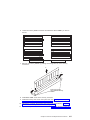
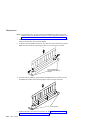
Removing Six-Position SCSI (SES) or SSA Disk Drive Bays . . . .
Replacing Six-Position SCSI (SES) or SSA Disk Drive Bays . . . .
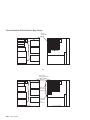
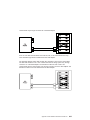
SCSI and SSA Cabling Configurations . . . . . . . . . . . .
Two-Position SCSI Disk Drive Bay Cabling . . . . . . . . . .
First Six-Position SCSI Disk Drive Bay Cabling . . . . . . . . .
Second Six-Position SCSI Disk Drive Bay Cabling. . . . . . . .
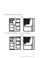
Two Six-Position SCSI RAID Bays Connected to a Single RAID Adapter
One Six-Position SCSI RAID Bay and One Six-Position SSA Bay . .
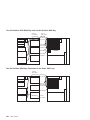
Two Six-Position SSA Bays Connected to the Same SSA Loop . . .
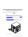
Replacing Non-Hot-Plug Drives . . . . . . . . . . . . . . .
Removing a Media Drive from the Optional Media Position . . . . .
Replacing a Media Drive in the Optional Media Position . . . . . .
Removing a Disk Drive from the Two-Position Disk Drive Bay . . . .
Replacing a Disk Drive in the Two-Position Disk Drive Bay . . . . .
.
.
.
.
.
.
.
.
.
.
.
.
.
.
.
.
.
.
.
.
.
.
.
.
.
.
.
.
.
.
.
.
.
.
.
.
.
.
.
.
.
.
.
.
.
.
.
.
.
.
.
.
.
.
.
.
.
.
.
.
.
.
.
.
.
.
.
.
.
.
.
.
.
.
.
.
.
.
.
.
.
.
.
.
.
.
.
.
.
.
.
.
.
.
.
.
.
.
.
.
.
.
.
.
.
.
.
.
.
.
.
.
.
.
.
.
.
.
.
.
.
.
.
334
334
335
335
336
336
336
338
339
339
339
339
340
340
341
341
342
342
343
343
343
343
343
344
344
345
346
350
352
355
355
356
357
357
358
358
359
359
360
360
362
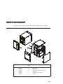
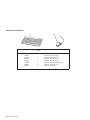
Chapter 10. Parts Information .
Covers . . . . . . . . .
Right Side . . . . . . . .
Left Side . . . . . . . .
Accessories . . . . . . .
Power Cords . . . . . .
Keyboards and Mouse . . .
.
.
.
.
.
.
.
.
.
.
.
.
.
.
.
.
.
.
.
.
.
365
365
367
370
372
372
374
Service Guide
.
.
.
.
.
.
.
.
.
.
.
.
.
.
.
.
.
.
.
.
.
.
.
.
.
.
.
.
.
.
.
.
.
.
.
.
.
.
.
.
.
.
.
.
.
.
.
.
.
.
.
.
.
.
.
.
.
.
.
.
.
.
.
.
.
.
.
.
.
.
.
.
.
.
.
.
.
.
.
.
.
.
.
.
.
.
.
.
.
.
.
.
.
.
.
.
.
.
Appendix A. Environmental Notices.
Product Recycling and Disposal . . .
Acoustical Noise Emissions . . . .
Declared Acoustical Noise Emissions .
.
.
.
.
.
.
.
.
.
.
.
.
.
.
.
.
.
.
.
.
.
.
.
.
.
.
.
.
.
.
.
.
.
.
.
.
.
.
.
.
.
.
.
.
.
.
.
.
.
.
.
.
.
.
.
.
.
.
.
.
Appendix B. Notices .
.
.
.
.
.
.
.
.
.
.
.
.
.
.
. 377
Test
. .
. .
. .
. .
. .
.
.
.
.
.
.
.
.
.
.
.
.
.
.
.
.
.
.
.
.
.
.
.
.
.
.
.
.
.
.
.
.
.
.
.
.
.
.
.
.
.
.
.
.
.
.
.
.
.
.
.
.
.
.
.
.
.
.
.
.
.
.
.
.
.
.
379
379
380
380
380
381
. . . . . . .
. . . . . . .
. . . . . . .
. . . . . . .
. . . . . . .
Configuration Files
. . . . . . .
. . . . . . .
. . . . . . .
. . . . . . .
. . . . . . .
. . . . . . .
. . . . . . .
. . . . . . .
. . . . . . .
. . . . . . .
. . . . . . .
. . . . . . .
. . . . . . .
. . . . . . .
. . . . . . .
. . . . . . .
. . . . . . .
.
.
.
.
.
.
.
.
.
.
.
.
.
.
.
.
.
.
.
.
.
.
.
.
.
.
.
.
.
.
.
.
.
.
.
.
.
.
.
.
.
.
.
.
.
.
.
.
.
.
.
.
.
.
.
.
.
.
.
.
.
.
.
.
.
.
.
.
.
.
.
.
.
.
.
.
.
.
.
.
.
.
.
.
.
.
.
.
.
.
.
.
383
383
383
383
384
386
386
387
387
387
388
388
388
389
390
391
391
393
395
397
399
402
405
.
.
.
.
.
.
.
.
.
. 409
. 409
. 409
.
.
.
.
.
Appendix C. Service Processor Setup
Service Processor Setup Checklist . .
Testing the Setup . . . . . . .
Testing Call-In . . . . . . .
Testing Call-Out . . . . . . .
Serial Port Configuration . . . .
and
. .
. .
. .
. .
. .
Appendix D. Modem Configurations . . . .
Sample Modem Configuration Files . . . . .
Generic Modem Configuration Files . . . .
Specific Modem Configuration Files . . . .
Configuration File Selection . . . . . . . .
Examples for Using the Generic Sample Modem
Customizing the Modem Configuration Files . .
IBM 7852-400 DIP Switch Settings . . . . .
Xon/Xoff Modems . . . . . . . . . .
Ring Detection . . . . . . . . . . .
Terminal Emulators . . . . . . . . . .
Recovery Procedures . . . . . . . . .
Transfer of a Modem Session . . . . . . .
Recovery Strategy . . . . . . . . . .
Prevention Strategy . . . . . . . . . .
Modem Configuration Sample Files . . . . .
Sample File modem_m0.cfg . . . . . . .
Sample File modem_m1.cfg . . . . . . .
Sample File modem_z.cfg. . . . . . . .
Sample File modem_z0.cfg . . . . . . .
Sample File modem_f.cfg . . . . . . . .
Sample File modem_f0.cfg . . . . . . .
Sample File modem_f1.cfg . . . . . . .
.
.
.
.
.
.
.
.
.
.
.
.
375
375
375
375
Appendix E. SSA Problem Determination Procedures
Disk Drive Module Power-On Self-Tests (POSTs) . . .
Adapter Power-On Self-Tests (POSTs) . . . . . .
.
.
.
Appendix F. SSA Software and Microcode Errors . .
Service Request Numbers (SRNs) . . . . . . . .
SRN Table . . . . . . . . . . . . . . .
Using the SRN Table . . . . . . . . . . .
Software and Microcode Errors . . . . . . . .
FRU Names and Abbreviations Used in the SRN Table
SSA Loop Configurations That Are Not Valid . . . .
SSA Location Code Format . . . . . . . . . .
. . . . . . . . . 411
. . . . . . . . . 411
. . . . . . . . . 411
. . . . . . . . . 411
. . . . . . . . . 411
. . . . . . . . . 412
. . . . . . . . . 420
. . . . . . . . . 421
Contents
ix
x
Service Guide
SSA Loops and Links . . . .
The SSA Adapter . . . .
Disk Drive Module Strings. .
Pdisks, Hdisks, and Disk Drive
Rules for SSA Loops . . .
Loops and Data Paths . . .
. . . . . . . .
. . . . . . . .
. . . . . . . .
Module Identification .
. . . . . . . .
. . . . . . . .
.
.
.
.
.
.
.
.
.
.
.
.
.
.
.
.
.
.
.
.
.
.
.
.
.
.
.
.
.
.
.
.
.
.
.
.
.
.
.
.
.
.
.
.
.
.
.
.
.
.
.
.
.
.
Index
.
.
.
.
.
.
.
.
.
. 427
.
.
.
.
.
.
.
.
.
.
.
.
.
.
.
.
422
423
423
423
424
424
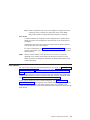
Safety Notices
A danger notice indicates the presence of a hazard that has the potential of causing
death or serious personal injury. Danger notices appear on the following pages:
v xii
v 48
v 299
v 329
A caution notice indicates the presence of a hazard that has the potential of causing
moderate or minor personal injury. Caution notices appear on the following pages:
v xii
v xii
v 48
v 299
v 359
Note: For a translation of these notices, see the System Unit Safety Information
manual, order number SA23-2652.
xi
Electrical Safety
Observe the following safety instructions any time you are connecting or disconnecting
devices attached to the server.
DANGER
An electrical outlet that is not correctly wired could place hazardous voltage
on metal parts of the system or the devices that attach to the system. It is the
responsibility of the customer to ensure that the outlet is correctly wired and
grounded to prevent an electrical shock.
Before installing or removing signal cables, ensure that the power cables for
the system unit and all attached devices are unplugged.
When adding or removing any additional devices to or from the system,
ensure that the power cables for those devices are unplugged before the
signal cables are connected. If possible, disconnect all power cables from the
existing system before you add a device.
Use one hand, when possible, to connect or disconnect signal cables to
prevent a possible shock from touching two surfaces with different electrical
potentials.
During an electrical storm, do not connect cables for display stations, printers,
telephones, or station protectors for communications lines.
CAUTION:
This product is equipped with a three–wire power cable and plug for the user’s
safety. Use this power cable with a properly grounded electrical outlet to avoid
electrical shock.
Laser Safety Information
CAUTION:
This product may contain a CD-ROM which is a class 1 laser product.
Laser Compliance
All lasers are certified in the U.S. to conform to the requirements of DHHS 21 CFR
Subchapter J for class 1 laser products. Outside the U.S., they are certified to be in
compliance with the IEC 825 (first edition 1984) as a class 1 laser product. Consult the
label on each part for laser certification numbers and approval information.
xii
Service Guide
CAUTION:
All IBM laser modules are designed so that there is never any human access to
laser radiation above a class 1 level during normal operation, user maintenance,
or prescribed service conditions. Data processing environments can contain
equipment transmitting on system links with laser modules that operate at
greater than class 1 power levels. For this reason, never look into the end of an
optical fiber cable or open receptacle. Only trained service personnel should
perform the inspection or repair of optical fiber cable assemblies and receptacles.
Preface
xiii
xiv
Service Guide
Data Integrity and Verification
These computer systems contain mechanisms designed to reduce the possibility of
undetected data corruption or loss. This risk, however, cannot be eliminated. Users who
experience unplanned outages, system failures, power fluctuations or outages, or
component failures must verify the accuracy of operations performed and data saved or
transmitted by the system at or near the time of the outage or failure. In addition, users
must establish procedures to ensure that there is independent data verification before
relying on such data in sensitive or critical operations. Users should periodically check
our support websites for updated information and fixes applicable to the system and
related software.
xv
xvi
Service Guide
About This Book
This book provides maintenance information that is specific to the 25F/80, 256/F0 and
256/F1, as well as to adapters and attached devices that do not have their own service
information. In this book, the 25F/80, 256/F0 and 256/F1 are hereafter referred to as
the ″system″ or the ″server.″
This book also contains Maintenance Analysis Procedures (MAPs) that are not common
to other systems. MAPs that are common to all systems are contained in the Diagnostic
Information for Multiple Bus Systems.
This book is used by the service technician to repair system failures. This book
assumes that the service technician has had training on the system unit.
ISO 9000
ISO 9000 registered quality systems were used in the development and manufacturing
of this product.
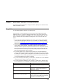
Related Publications
The following publications are available for purchase:
v The System Unit Safety Information, order number SA23-2652, contains translations
of safety information used throughout this book.
v The 26F/80, 256/F0, and 256/F1 User’s Guide, order number SA23-2534, contains
information to help users set up, install options, configure and modify the system,
and solve minor problems.
v The Diagnostic Information for Multiple Bus Systems, order number SA23-2769,
contains common diagnostic procedures, error codes, service request numbers, and
failing function codes. This manual is intended for trained service technicians.
v The PCI Adapter Placement Reference, order number SA23-2504, contains
guidelines for placement of PCI adapters into I/O slots of Models 25F/80, 256/F0,
and 256/F1 systems. This manual is intended to help when planning to install
adapters so that optimum, tested adapter configurations are used.
v The Adapters, Devices, and Cable Information for Multiple Bus Systems, order
number SA23-2778, contains information about adapters, external devices, and
cabling. This manual is intended to supplement information found in the Diagnostic
Information for Multiple Bus Systems.
v The Site and Hardware Planning Information, order number SA38-0508, contains
information to help you plan your installation.
v SSA Adapters User’s Guide and Maintenance Information, order number SA33-3272,
is intended to help users and service representatives work with and diagnose
problems with SSA adapters and devices.
v RS/6000 SP Systems Service Guide, order number GA22-7442, is intended to help
users and service representatives work with and diagnose problems with SP
systems.
xvii
v Clustered Eserver Installation and Service Guide, order number SA22-7863, is
intended to help users and service representatives work with and diagnose problems
with clustered Eserver systems.
Trademarks
The following terms are trademarks of International Business Machines Corporation in
the United States, other countries, or both:
v AIX
Other company, product, and service names may be trademarks or service marks of
others.
xviii
Service Guide
Chapter 1. Reference Information
This chapter provides an overview of the system, including a logical description and a
physical overview of the system. Additional details pertaining to the system are also
provided. These include:
v Memory overview and placement rules
v General description of the operator panel
v System location rules and descriptions
v Powering on and off the system
v Power flow
v Data flow
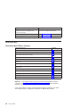
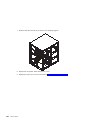
Overview
This system is a high-performance entry server in a deskside system unit. It provides
64-bit symmetric multiprocessing (SMP) with true multithreaded application support in a
double-wide deskside box.
1
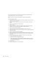
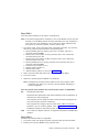
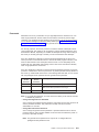
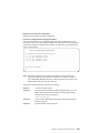
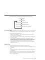
Bus Architecture
Ten PCI slots are available:
v Six of the slots are 64-bit PCI full-sized slots at 66 MHz, 3.3 volts.
v Four of the slots are 64-bit PCI full-sized slots at 33 MHz, 5 volts.
v Bus 1 contains:
– PCI slot 3
– PCI slot 4
– PCI slot 5
– Integrated Ultra2 SCSI
v Bus 2 contains:
– PCI slot 6
– PCI slot 7
– PCI slot 8
– Integrated Ethernet (32-bit)
v Bus 3 contains:
– PCI slot 9
– PCI slot 10
– PCI slot 11
– PCI slot 12
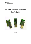
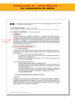
The PCI buses support both 32-bit and 64-bit adapters. Slots 3, 4, 5, 8, 9, and 10
support adapters running at 3.3 volts at up to 66 MHz. Slots 6, 7, 11, and 12 support
adapters running at 5 volts at 33 MHz. The server data flows are shown in “Data Flow
with One-Way Processor” on page 5 and “Data Flow with Two- to Six-Way Processor”
on page 6.
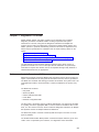
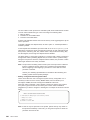
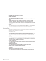
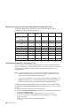
Microprocessor
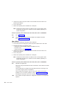
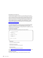
The Models 25F/80 and 256/F1 can have one to six processors, of either of two
processor types, in various configurations:
v Minimum configuration is one 450 MHz processor, which has 2 MB of L2 cache.
v Two or four 450 MHz processors, each with 4 MB of L2 cache.
v Six 500 MHz processors, each with 4 MB of L2 cache.
OR
v Minimum configuration is either one 600 MHz processor, which has 2 MB of L2
cache, or one 750 MHz processor, which has 8 MB of L2 cache.
v Two or four 600 MHz processors, each with 4 MB of L2 cache.
v Two or four 750 MHz processors, each with 8 MB of L2 cache.
v Six 668 MHz processors, each with 8 MB of L2 cache.
v Six 750 MHz processors, each with 8 MB of L2 cache.
The Model 256/F0 can have one to four processors, of either of two processor types, in
various configurations:
v Minimum configuration is one 450 MHz processor, which has 2 MB of L2 cache.
v Two or four 450 MHz processors, each with 4 MB of L2 cache.
OR
2
Service Guide
v Minimum configuration is either one 600 MHz processor, which has 2 MB of L2
cache, or one 750 MHz processor, which has 8 MB of L2 cache.
v Two or four 600 MHz processors, each with 4 MB of L2 cache.
v Two or four 750 MHz processors, each with 8 MB of L2 cache.
Memory
v 256 MB (minimum) to 32 GB (maximum).
v One or two memory riser cards; each riser card has 16 sockets. 128 MB, 256 MB,
512 MB and 1 GB dual inline memory modules (DIMMs) are available.
v Certain 32 MB DIMMs from older systems can also be used when upgrading the
system memory.
Media Drives
Three media bays are available:
v Optional media bay (D17) that can accommodate 5.25-inch drives such as CD-ROM
drives, tape drives, or other removable media drives
v Standard CD-ROM drive with sliding tray (D16)
v Standard 3.5-inch, 1.44 MB diskette drive (D15)
Internal Hard Disk Drives
Three bays are available to install disk drives, as follows:
v Disk bay 3, a two-position SCSI disk drive bay (D13 and D14)
This bay supports two SCSI disk drives.
v Disk bay 2, a six-position hot-plug disk drive bay (D07 - D12)
This bay can accommodate a six-position SCSI disk drive cage or a six-position SSA
disk drive cage.
v Disk bay 1, a six-position hot-plug disk drive bay (D01 - D06)
This bay can accommodate a six-position SCSI disk drive cage or a six-position SSA
disk drive cage.
Power Supply
v 575-watt power supply (two required), usable with 100-127 V ac (low voltage) or
200-240 V ac (high voltage)
Keyboard
v Standard: 101-key enhanced keyboard
v Optional: 101/102-key or 106-key enhanced keyboard
Mouse
v Three-button
Chapter 1. Reference Information
3
Operator Panel
v 32-character LED diagnostics display
v Power and Reset buttons
Input/Output Ports
v 25-pin parallel
v 9-pin serial (4)
v Keyboard
v Mouse
v Ultra 2 SCSI LVD
v 10/100BaseT Ethernet
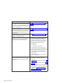
Security Features
v Power-on password
v Privileged-access password
v Unattended start mode
4
Service Guide
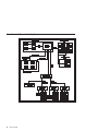
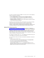
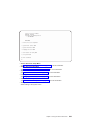
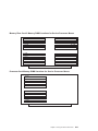
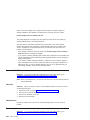
Data Flow with One-Way Processor
System Board
Processor Card (1 way only)
L2
Memory
Controller
6XX
Bus 0
P
SMI
SMI
SMI BUS 0, 1
SMI BUS 2, 3
Memory Card
(1 only is optional)
SMI
SMI
SMI
SMI
RIO
(2)
256 MB - 16 GB
PCI Host Bridge
64-bit
PCI Bus 1
64-bit
PCI Bus 2
Converged Support
Processor
PCI to PCI
Bridge 2
PCI to PCI
Bridge 1
SCSI
3.3
V
3.3
V
3.3
V
S
L
O
T
3
S
L
O
T
4
S
L
O
T
5
10/100
E’net
PCI to PCI
Bridge 3
5V
5V
3.3
V
3.3
V
3.3
V
5V
5V
S
L
O
T
6
S
L
O
T
7
S
L
O
T
8
S
L
O
T
9
S
L
O
T
10
S
L
O
T
11
S
L
O
T
12
Chapter 1. Reference Information
5
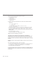
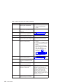
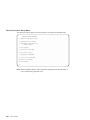
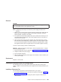
Data Flow with Two- to Six-Way Processor
System Board
2-Way System
L2
6-Way System
P
Memory
Controller
6XX
Bus 0
L2
P
L2
P
P
P
P
L2
4-Way System
SMI BUS 2, 3
L2
P
SMI
SMI
SMI
SMI
P
RIO
(2)
L2
256 MB - 32 GB
PCI Host Bridge
64-bit
PCI Bus 1
64-bit
PCI Bus 2
Converged Support
Processor
PCI to PCI
Bridge 2
PCI to PCI
Bridge 1
SCSI
Service Guide
L2
OR
SMI BUS 0, 1
Memory Cards
(1 or 2)
6
L2
6XX
Bus 1
3.3
V
3.3
V
3.3
V
5V
S
L
O
T
3
S
L
O
T
4
S
L
O
T
5
S
L
O
T
6
10/100
E’net
5V 3.3
V
S S
L
L
O O
T T
8
7
PCI to PCI
Bridge 3
3.3 3.3
V
V
5V 5 V
S
L
O
T
9
S
L
O
T
11
S
L
O
T
10
S
L
O
T
12
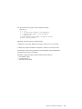
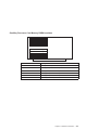
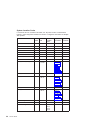
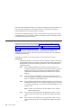
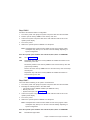
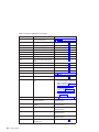
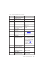
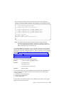
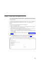
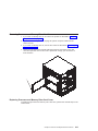
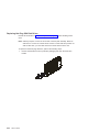
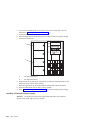
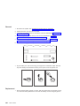
Power Flow
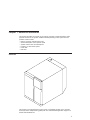
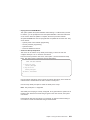
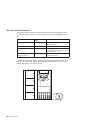
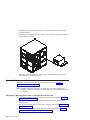
The following diagram shows the right side of the system with the cover removed.
19
18
20
17
16
1
15
14
13
2
12
11
10
9
8
1
2
3
4
5
6
7
8
9
10
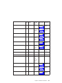
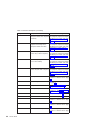
110 V ac/220 V ac power into system
board assembly
110 V ac/220 V ac power into power
supply V1
2.5 V dc out of power supply V1 into
system board
2.5/3.3 V dc out of power supply V1 into
system board
3.3 V dc out of power supply V1 into
system board
5 V dc out of power supply V1 into
system board
Ground out of power supply V1 into
system board
12 V dc out of power supply V1 into
system board
I2C to DASD bay 1 (DB1)
Power 2 to DASD bay 1 (DB1)
7
6
5
4
3
11
Power 1 to DASD bay 1 (DB1)
12
Power 1 to DASD bay 2 (DB2)
13
Power to cooling fans
14
Power 2 to DASD bay 2 (DB2)
15
Signal to diskette drive
16
I2C to DASD bay 2 (DB2)
17
Power to diskette drive
18
Signal to operator panel
19
20
Power to media drive bay
Power 1 to two-position disk drive bay 3
(DB3)
Chapter 1. Reference Information
7
Powering Off and Powering On the System
This section provides procedures for powering off and powering on the system.
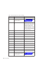
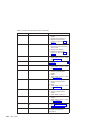
Powering Off the System
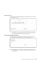
If the system is operating under AIX, type the shutdown command to power off the
system.
If you cannot use this method, you can power off the system by using the following
operator-panel power button procedure:
Attention: Using the operator-panel power button to power off the system might
cause unpredictable results in the data files, and the next IPL will take longer to
complete.
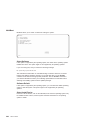
1. Open the access door.
2. Press the power button on the operator panel.
B0FF appears in the operator panel display. The operator panel power LED starts
blinking at a fast rate.
When the power-off sequence is complete, the system goes into standby power mode,
as evidenced by the following:
v OK displays in the operator panel display.
v The operator panel power LED starts blinking at a slow rate.
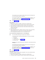
Powering On the System
Perform the following steps to power on the system:
1. Open the access door. Look for OK on the operator panel display, which indicates
that the system is in standby mode.
2. Press the power button on the operator panel.
The power LED on the operator panel starts blinking at a fast rate. Checkpoint
codes (9xxx) appear in the operator panel display. For details, see “IPL Flow” on
page 77.
When the power-on sequence is complete, the power LED on the operator panel stops
blinking and stays on.
Powering Off and Powering On the System Using the Service Processor
The system can be powered off and on using the System Power Control menu, which is
a service processor menu that is available to the privileged user. See “System Power
Control Menu” on page 254.
8
Service Guide
Console Strategy
The firmware starts a console-selection sequence at system boot time if any of the
following is true:
v A console has not yet been selected.
v A previous console selection sequence timed out.
v A change in the system configuration affects the console (keyboard
installed/removed, mouse installed/removed, graphics adapter installed/removed or
moved to another PCI slot).
The console-selection sequence allows you to select (from the appropriate input device)
one of the available console devices. If no console is selected within approximately 60
seconds, serial port 1 (S1) is selected as the console and the selection sequence times
out.
After a console has been selected, the console-selection sequence is only started at
boot time if there is a change in the system configuration (as described above), or the
contents of the system’s nonvolatile memory (NVRAM) are lost.
Note: Moving an ASCII terminal from one serial port to another (from S1 to S2) cannot
be detected by the firmware, so it does not constitute a configuration change.
You can also initiate a firmware console selection sequence from the System
Management Services (SMS) menus.
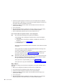
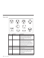
Power-On Self-Test
After power is turned on and before the operating system is loaded, the system does a
power-on self-test (POST). This test performs checks to ensure that the hardware is
functioning correctly before the operating system is loaded. During the POST, a POST
screen displays and POST indicators appear on the fimware console (if one is
connected). The next section describes the POST indicators and functions that can be
accessed during the POST.
POST Indicators
POST (power-on self-test) indicators indicate tests that are being performed as the
system is preparing to load the operating system. The POST indicators are words that
display on the system console. Each time that the system starts another step in the
POST, a POST indicator word appears on the console. Each word is an indicator of the
tests that are being performed.
Chapter 1. Reference Information
9
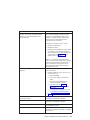
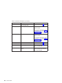
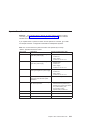
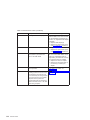
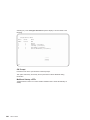
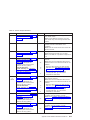
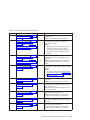
The POST screen displays the following words:
Memory
Memory test
Keyboard
Initialize the keyboard and mouse. The window for pressing a key to
access the System Management Services, or to initiate a service
mode boot, is now open. See “POST Keys” for more information.
Network
Self-test on network adapters
SCSI
Adapters are being initialized
Speaker
Sounds an audible tone at the end of POST
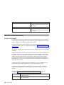
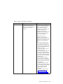
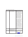
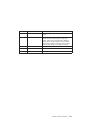
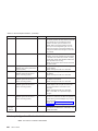
POST Keys
The POST keys, if pressed after the keyboard POST indicator displays and before the
last POST indicator (speaker) displays, cause the system to start services or to initiate
service mode boots used for configuring the system and diagnosing problems. The keys
are described below:
Note: The program function keys (F1-F12) on a keyboard attached to the system unit
are no longer used and will be ignored during POST. After the keyboard POST
indicator displays, you must use the numeric number keys to enter input.
1 Key
The numeric 1 key, when pressed during POST, starts the System Management
Services (SMS) interface.
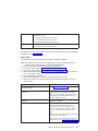
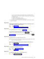
5 Key
The numeric 5 key, when pressed during POST, initiates a system boot in service mode
using the default service mode boot list.
This mode attempts to boot from the first device of each type found in the list. It does
not search for other bootable devices of that type if the first device is not bootable.
Instead, it continues to the next device type in the list. The firmware supports up to five
entries in the boot list.
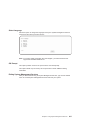
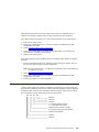
The default boot sequence is:
1. Diskette
2. CD-ROM
3. Hard file
4. Tape drive (if installed)
5. Network
a. Token ring
b. Ethernet
10
Service Guide
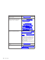
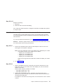
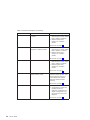
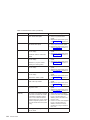
6 Key
The numeric 6 key works like the numeric 5 key, except that firmware uses the
customized service mode bootlist that was set up using the AIX service aids.
8 Key
To enter the open firmware command line, press the numeric 8 key after the word
keyboard displays and before the last word (speaker) displays during startup. After you
press the 8 key, the remaining POST indicators display until initialization completes.
When initialization and POST are complete, the open firmware command line (an OK
prompt) displays.
The open firmware command line should only be used by service personnel to obtain
additional debug information.
To exit from the open firmware command prompt, type reset-all or power off the
system and reboot.
Chapter 1. Reference Information
11
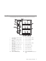
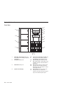
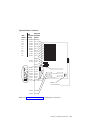
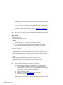
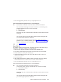
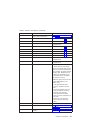
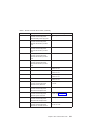
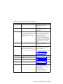
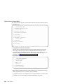
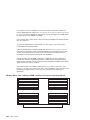
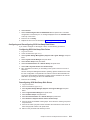
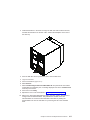
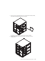
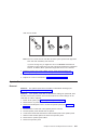
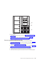
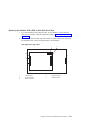
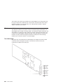
System Unit Locations
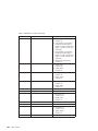
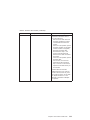
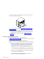
Front View
1
2
14
3
4
13
5
6
12
7
11
8
10
1
12
2
Media Bay (Optional Drive): Bay D17 This position is for installing an optional
media device.
CD-ROM Drive: Bay D16
3
Diskette Drive: Bay D15
9&
10
4
Operator Panel Display
11 14
Service Guide
5&
6
7&
8
9
Two-Position SCSI Disk Drive Bay: Bay
D14 (top), Bay D13 (bottom). Bays for
the installation of two SCSI disk drives.
Disk Drive Bay: Bank DB2 (top), Bay
DB1 (bottom) (SES or SSA). Bays for the
installation of SCSI or SSA disk drives or
RAID arrays.
Disk Drive: Bay D07 (top left), Bay D12
(top right). Bay D01 (bottom left), Bay
D06 (bottom right). Disk drives in a SCSI
or SSA disk drive bay.
Fan Positions: Fan F01 (bottom), Fan
F04 (top). Fans F01 and F03 are
required. Fans F02 and F04 are required
only for the redundant power option.
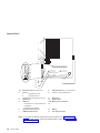
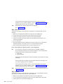
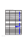
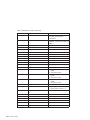
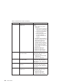
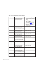
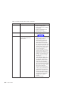
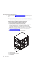
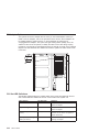
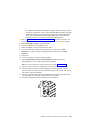
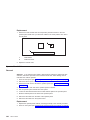
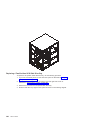
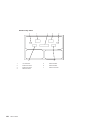
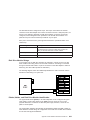
Rear View
1
12
11
14
13
64-bit 5V Slots
at 33MHz
10
64-bit 3.3V Slots
at 66MHz
09
08
07
06
05
04
03
12
64-bit 5V Slots
at 33MHz
64-bit 3.3V Slots
at 66MHz
2
3
4
11
10
1&
2
3
4
5
6
7
9
7
8
Expansion Slots: For adding PCI
adapters.
1
Expansion Slot C12
2
Expansion Slot C3
Test Port: For testing during
manufacturing.
Parallel Port: For connecting a parallel
printer or other parallel devices.
External SCSI Port: For connecting
external SCSI devices.
100BaseT Ethernet Port: For attaching
your computer to an Ethernet/Twisted
pair connection through a 100BaseT
connector.
9-Pin Serial Ports: For a TTY terminal,
modem, or other serial devices.*
6
5
8
Keyboard Port: For keyboard
connection.
9
Mouse Port: For mouse connection.
10
Power Connector: For connecting the
power cable.
11 & Power Supplies: V1 (bottom), V2
12
(middle) Power supplies are installed
from the side of the system unit.
13
Redundant Power Supply V3
(Optional)
14
Disk Drive Bulkhead Connector: For
attaching internal disk drive bays to an
SSA adapter or connecting internal
hardfiles to the external SCSI port (5) or
a SCSI adapter.
*Serial ports 1 and 2 can only be used for service processor menus. No
″heartbeat-type″ devices can be used on these ports. ″Heartbeat-type″ devices or
cables must be installed on serial port 3 or serial port 4.
Chapter 1. Reference Information
13
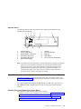
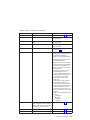
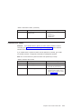
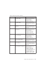
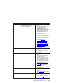
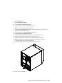
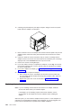
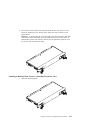
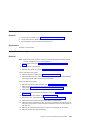
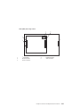
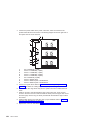
System Board
1
.
.
.
2
3
4
5a
6
5b
7
8
9
10
11
12
13
16
12
13
17
14
15
1&
2
3
4
5
Expansion Slots: For adding PCI
adapters.
1
Expansion Slot C12
2
Expansion Slot C3
Test Port: For manufacturing use only.
Parallel Port
SCSI Port
v 5a Internal Port 1 speed must be set
to fast/wide
6
7
v 5b External Port 2 Ultra-2
Processor Card Connector
100BaseT Ethernet Port
811
9-Pin Serial Ports: For a TTY terminal,
modem, or other serial devices.
12
Mouse Port
13
Keyboard Port
14 & Memory Riser Card Slots
15
16
17
Battery
Fan Cable Connector
Note: For locations of diskette and operator panel connectors, see “Power Flow” on
page 7. For AIX location codes and physical location codes, see “System Board
Locations” on page 21.
14
Service Guide
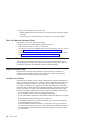
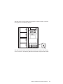
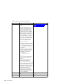
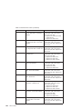
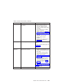
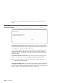
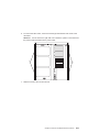
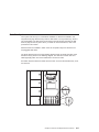
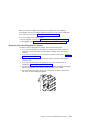
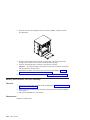
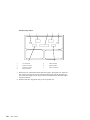
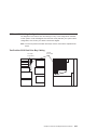
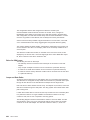
Operator Panel
The following diagram shows the locations of the operator panel display and the
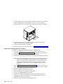
operator panel pushbuttons.
1
2
4
5
6
7
R
11
10
1
2
3
4
5
6
3
9
8
Power-On Button
Power-On LED (Green)
System Attention LED (Yellow)
SCSI Activity LED (Green)
LAN Activity LED (Green)
Operator Panel Display
7
8
9
10
11
Speaker
Serial Number Plate
Reset Icon
Reset Button
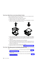
Service Processor Reset Button
Note: The service processor reset button must be activated very carefully. An insulated
paper clip is recommended. Unbend the clip so that it has a straight section
about two inches long. Insert the clip straight into the hole, keeping the clip
perpendicular to the plastic bezel. When you engage the reset switch, you
should feel the detent of the switch. After you press the switch, the service
processor resets and then shuts down the system.
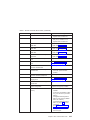
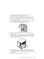
System Memory
Two slots are available for memory riser cards. Each riser card had 16 sockets. See
“System Board” on page 14, which illustrates the positions of the memory riser cards in
the system.
Four sizes of DIMMs are available: 128 MB, 256 MB, 512 MB, and 1 GB. Certain 32
MB DIMMs from older RS/6000 systems can also be used when upgrading system
memory.
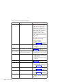
One-Way Processor Memory Placement Rules
The rules for one-way processor memory are as follows:
v Minimum memory is 1 pair of DIMMs in slots 1 and 8 (see “Processor Card Memory
DIMM Locations for Service Processor Menus” on page 263).
v Maximum memory is 4 DIMM pairs in slots 1 through 8 (see “Processor Card
Memory DIMM Locations for Service Processor Menus” on page 263).
v Each memory riser slot must have a memory filler card installed.
Chapter 1. Reference Information
15
v When you are installing a memory riser card:
– Memory DIMMs must be moved from the one-way processor card to the memory
riser card.
– The memory riser card must then have a minimum of 1 quad (four DIMMs).
Riser Card Memory Placement Rules
The rules for memory riser cards are as follows:
v Memory quads must contain DIMMs of equal memory size.
v Quad memory size may be mixed on a riser card.
v The minimum memory is four DIMMs, which must occupy quad A, slots 1, 2, 15 and
16 (see “Memory Riser Card and Memory DIMM Locations” on page 22).
v Populate the riser card starting with quad A and continuing with quads B, C, and D
(see “Memory Riser Card and Memory DIMM Locations” on page 22).
Logical and Physical Locations
This system uses physical location codes in conjunction with AIX location codes to
provide mapping of the failing field replaceable units (FRUs). The location codes are
produced by the system unit’s firmware and the AIX operating system.
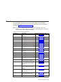
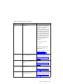
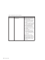
Physical Location Codes
Physical location codes provide a mapping of logical functions in a platform (or
expansion sites for logical functions, such as connectors or ports) to their specific
locations within the physical structure of the platform.
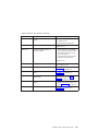
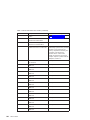
Location Code Format
The format for the location code is a string of alphanumeric characters separated by a
dash (–), slash (/), pound sign (#) or period (·) character. The base location is all of the
information preceding the slash (/) or pound sign (#). The base location identifies a
device that is connected to or plugged into the parent. Extended location information
follows the slash (/). Extended location information identifies a device that is part of the
parent, a connector, or a cable. Cable information follows the pound sign (#). Cable
information identifies a cable that is connector to parent. The following are examples:
v P1-C1 identifies a processor card C1 plugged into planar P1.
v P1-M1 identifies a memory riser card M1 plugged into planar P1.
v P-1-Z1-A3 identifies a SCSI device with SCSI ID 3 attached to SCSI bus 1 on planar
1.
v P1-K1 identifies a keyboard attached to K1 on planar P1.
v P1/S1 identifies serial port 1 controller on planar P1, the connector for serial port 1,
or the cable attached to serial port 1.
v P1-I2/E3 identifies an Ethernet controller 3, on the card in slot 2 (I2) on planar P1,
the connector for Ethernet controller 3, or the cable attached to Ethernet controller 3.
v P1-I2#E3 identifies the cable attached to Ethernet controller 3 on the card in slot 2
(I2) on planar P1.
16
Service Guide
The period (·) identifies sublocations (DIMMs on a memory riser card, SCSI addresses,
cables). The following are examples:
v P1-M1.4 identifies DIMM 4 on memory riser card 1 plugged into planar P1.
v P1-C1.1 identifies processor 1 on processor card 1 plugged into planar P1.
v P2-Z1-A3.1 identifies a SCSI device with SCSI address of LUN 1 at SCSI ID 3
attached to SCSI bus 1 from planar 2.
v P1-I2#E3.2 identifies the second in a series of cables attached to Ethernet controller
3 on the card in slot 2 (I2) on planar P1.
Depending on the AIX and firmware levels, AIX diagnostics may include the extended
location information when identifying a planar or card. The extended location
information or cable information is always included when identifying a cable or
connector. Location codes with extended location information that are displayed without
a description identifying the devices always identify the cable attached to the port.
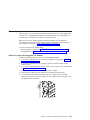
Multiple FRU Callout Instructions
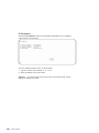
If an eight-digit error code appears in the operator panel display or as described in
Chapter 5, “Error Code to FRU Index” on page 99, a location code for a failing part may
also be specified. If the location code includes a blank space followed by a lowercase x
followed by a number, this is an error code with multiple FRU callouts. This error can
typically happen with memory DIMMs, memory riser cards, or processors and may
involve mixed types of parts. In this case, check the system’s configuration for FRU part
numbers to determine the appropriate set of FRUs.
For example, if the location code P1-M1.1 x2 was displayed, this indicates memory pair
A (two DIMMs) on the first memory riser card was suspected.
You can determine the FRU part numbers of the electronic assemblies in the system in
two ways:
v Using the service processor menus
From the general user menu, select Read VPD Image from Last System Boot,
then enter 90 to display detailed vital product data (VPD).
v Typing the lscfg -vp | pg command on the AIX command line
Type the following command: lscfg -vp | pg to display the detailed VPD of all
assemblies. Notice that the FRU part number information for processors and memory
DIMMs may be at the bottom of the command output.
Chapter 1. Reference Information
17
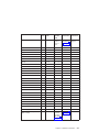
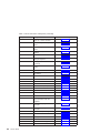
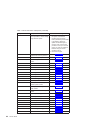
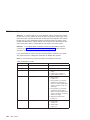
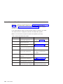
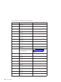
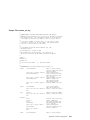
AIX Location Codes
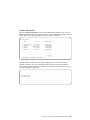
The basic formats of the AIX location codes are as follows:
v For non-SCSI devices/drives:
– AB-CD-EF-GH
v For SCSI devices/drives:
– AB-CD-EF-G,H
For planars, cards, and non-SCSI devices, the location code is defined as follows:
AB-CD-EF-GH
| | | |
| | | Device/FRU/Port ID
| | Connector ID
| devfunc Number, Adapter Number or Physical Location
Bus Type or PCI Parent Bus
v The AB value identifies a bus type or PCI parent bus as assigned by the firmware.
v The CD value identifies adapter number, adapter’s devfunc number, or physical
location. The devfunc number is defined as the PCI device number times 8, plus the
function number.
v The EF value identifies a connector.
v The GH value identifies a port, address, device, or FRU.
Adapters and cards are identified only with AB-CD.
The possible values for CD depend on the adapter/card. For pluggable PCI
adapters/cards, CD is the device’s devfunc number (PCI device number times 8, plus
the function number). The C and D are characters in the range of 0-9, and A-F (hex
numbers). The location codes therefore uniquely identify multiple adapters on individual
PCI cards.
EF is the connector ID, used to identify the adapter’s connector to which a resource is
attached.
GH is used to identify a port, device, or FRU. For example:
v For async devices, GH defines the port on the fanout box. The values are 00 to 15.
v For a diskette drive, H identifies either diskette drive 1 or 2. G is always 0.
v For all other devices, GH is equal to 00.
For integrated adapter, EF-GH is the same as the definition for a pluggable adapter. For
example, the location code for a diskette drive is 01-D1-00-00. A second diskette drive
is 01-D1-00-01.
18
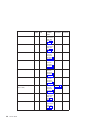
Service Guide
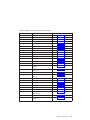
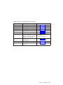
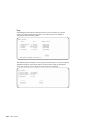
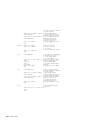
For SCSI devices, the location code is defined as follows:
AB-CD-EF-G,H
| | | | |
| | | | Logical Unit address of the SCSI Device
| | | Control Unit Address of the SCSI Device
| | Connector ID
| devfunc Number, Adapter Number or Physical Location
Bus Type or PCI Parent Bus
AB-CD-EF are the same as non-SCSI devices.
G defines the control unit address of the device. Values of 0 to 15 are valid.
H defines the logical unit address of the device. Values of 0 to 255 are valid.
A bus location code is also generated as 00-XXXXXXXX, where XXXXXXXX is
equivalent to the node’s unit address.
Examples of physical location codes and AIX location codes are:
v PCI adapter in Slot 1
v Location code P1-I1
v AIX location code 20-58
Chapter 1. Reference Information
19
AIX and Physical Location Code Reference Tables
The following diagrams identify the physical locations in the system. These locations
correspond to the tables on “System Location Codes” on page 24, which contain
location codes that are used to identify functional units in the system.
The following diagram shows the right side of the system with the cover removed.
Power Supply Locations
Physical
Location
Codes
V3
V2
V1
20
Service Guide
AIX
Location
Codes
System Board Locations
Slot
Name
C12
C11
C10
C9
C8
C7
C6
C5
C4
C3
Physical
AIX
Location Location
Codes
Codes
31-08
34-08
37-08
3A-08
27-08
2A-08
2D-08
14-08
17-08
1A-08
P1-I 12
P1-I 11
P1-I 10
P1-I 9
P1-I 8
P1-I 7
P1-I 6
P1-I 5
P1-I 4
P1-I 3
01-R1
11-08
Debug
P1-R1
P1-Z1
P1-C1
11-09
21-08
01-S4
01-S2
01-S3
01-S1
01-K1
01-O1
P1-Z2
P1-E1
P1-S4
P1-S2
P1-S3
P1-S1
P1-K1
P1-O1
Battery
Fan Connector
00-00
P1-M1
00-00
P1-M2
Note: See “System Board” on page 14 for descriptions of connectors.
Chapter 1. Reference Information
21
Memory Riser Card and Memory DIMM Locations
22
Service Guide
(15) A
(16) A
(13) B
(14) B
(11) C
(12) C
(9) D
(10) D
(7) D
(8) D
(5) C
(6) C
(3) B
(4) B
(1) A
(2) A
Location Code
Memory DIMMs
P1-M1.n
Memory DIMMs on riser card 1 (n denotes DIMM number)
P1-M2.n
Memory DIMMs on riser card 2 (n denotes DIMM number)
P1-M1.1 x4
Memory quad A (DIMMs 1, 2, 15, 16)
P1-M1.3 x4
Memory quad B (DIMMs 3, 4, 13, 14)
P1-M1.5 x4
Memory quad C (DIMMs 5, 6, 11, 12)
P1-M1.7 x4
Memory quad D (DIMMs 7, 8, 9, 10)
P1-M2.1 x2
Memory pair A (DIMMs 1 and 15)
P1-M2.1 x4
Memory quad A (DIMMs 1, 2, 15, 16)
P1-M2.3 x4
Memory quad B (DIMMs 3, 4, 13, 14)
P1-M2.5 x4
Memory quad C (DIMMs 5, 6, 11, 12)
P1-M2.7 x4
Memory quad D (DIMMs 7, 8, 9, 10)
P1-M1.1 x16
All memory DIMMs on riser card 1
P1-M2.1 x16
All memory DIMMs on riser card 2
P1-M1 x2
All memory DIMMs on riser cards 1 and 2
One-Way Processor Card Memory DIMM Locations
(8) A
(7) B
(6) C
(5) D
(4) D
(3) C
(2) B
(1) A
Location Code
Memory DIMMs
P1-C1-Mn
Memory DIMMs on processor card (n denotes DIMM number)
P1-C1-M1 x2
Memory pair A (DIMMs 1 and 8)
P1-C1-M2 x2
Memory pair B (DIMMs 2 and 7)
P1-C1-M3 x2
Memory pair C (DIMMs 3 and 6)
P1-C1-M4 x2
Memory pair D (DIMMs 4 and 5)
P1-C1-M1 x8
All memory DIMMs on processor card
Chapter 1. Reference Information
23
System Location Codes
If a returned value is not listed in this table, see ″Physical Location Code Standard
Prefixes″ under ″Diagnostic Numbers and Codes″ in Diagnostic Information for Multiple
Bus Systems.
FRU Name
Slot
Location
Name Code
System board
Processor Card
P1-C1
00-00
P1-C1
00-02
Processor 3
P1-C1
00-04
Processor 4
P1-C1
00-06
Processor 5
P1-C1
00-08
Processor 6
P1-C1
00-0A
Memory DIMMs (1-way)
P1-C1-M1 to 00-00
P1-C1-M8
M01
P1-M1
00-00
P1-M1.1 to
P1-M1.16
00-00
P1-M2
00-00
Memory DIMM 1-16
P1-M2.1 to
P1-M2.16
00-00
PCI Host Bridge Bus 1
P1
00-fff7f09000
ISA Bus
P1
10-80
PCI to PCI Bridge 1
P1
10-58,
10-5A,
10-5C,
10-5E
Memory DIMM 1-16
Service Guide
P1-C1
Processor 2
Memory riser card 2
Physical
Logical
Connection Connection
P1
C01
Processor 1
Memory riser card 1
24
AIX
Location
Code
M02
See
“One-Way
Processor
Card
Memory
DIMM
Locations”
on page 23
See
“Memory
Riser Card
and Memory
DIMM
Locations”
on page 22
See
“Memory
Riser Card
and Memory
DIMM
Locations”
on page 22
FRU Name
Slot
Location
Name Code
AIX
Location
Code
Physical
Logical
Connection Connection
C03
P1/I3
10-5A
J10, 64 BIT PCI to PCI
See Note 1 Bridge 1
on page 29.
P1-I3
1A-08 to
1A-0F or
1B-xx or
1C-xx
J10, 64 BIT PCI to PCI
See Note 1 Bridge 1
on page 29.
P1/I4
10-5C
J11, 64 BIT PCI to PCI
See Note 1 Bridge 1
on page 29.
P1-I4
17-08 to
17-0F or
18-xx or
19-xx
J11, 64 BIT PCI to PCI
See Note 1 Bridge 1
on page 29.
P1/I5
10-5E
J12, 64 BIT PCI to PCI
See Note 1 Bridge 1
on page 29.
PCI Slot 5 Device
P1-I5
14-08 to
14-0F or
15-xx or
16-xx
J12, 64 BIT PCI to PCI
See Note 1 Bridge 1
on page 29.
Internal SCSI controller
P1/Z1
11-08
PCI to PCI
Bridge 1
External SCSI controller
P1/Z2
11-09
PCI to PCI
Bridge 1
PCI Host Bridge Bus 2
P1
00-fff7f0a000
PCI to PCI Bridge 2
P1
20-58,
20-5A,
20-5B
(unused),
20-5C,
20-5E
P1/I6
20-5A
J13, 64 BIT PCI to PCI
See Note 1 Bridge 2
on page 29.
P1-I6
2D-08 to
2D-0F or
2E-xx or
2F-xx
J13, 64 BIT PCI to PCI
See Note 1 Bridge 2
on page 29.
P1/I7
20-5C
J14, 64 BIT PCI to PCI
See Note 1 Bridge 2
on page 29.
PCI Slot 3
PCI Slot 3 Device
PCI Slot 4
C04
PCI Slot 4 Device
PCI Slot 5
PCI Slot 6
C05
C06
PCI Slot 6 Device
PCI Slot 7
C07
Chapter 1. Reference Information
25
FRU Name
Slot
Location
Name Code
AIX
Location
Code
Physical
Logical
Connection Connection
P1-I7
2A-08 to
2A-0F or
2B-xx or
2C-xx
J14, 64 BIT PCI to PCI
See Note 1 Bridge 2
on page 29.
P1/I8
20-5E
J14, 64 BIT PCI to PCI
See Note 1 Bridge 2
on page 29.
PCI Slot 8 Device
P1-I8
27-08 to
27-0F or
28-xx or
29-xx
J14, 64 BIT PCI to PCI
See Note 1 Bridge 2
on page 29.
Integrated Ethernet
P1/E1
21-08
PCI to PCI Bridge 3
P1
20-60,
20-62,
20-63,
20-64, 20-65
(unused),
20-66,
P1/I9
20-60
J16, 64 BIT PCI to PCI
See Note 1 Bridge 3
on page 29.
P1-I9
3A-08 to
3A-0F or
3B-xx or
3C-xx
J16, 64 BIT PCI to PCI
See Note 1 Bridge 3
on page 29.
P1/I10
20-62
J17, 64 BIT PCI to PCI
See Note 1 Bridge 3
on page 29.
P1-I10
37-08 to
37-0F or
38-xx or
39-xx
J17, 64 BIT PCI to PCI
See Note 1 Bridge 3
on page 29.
P1/I11
20-64
J18, 64 BIT PCI to PCI
See Note 1 Bridge 3
on page 29.
P1-I11
34-08 to
34-0F or
35-xx or
36-xx
J18, 64 BIT PCI to PCI
See Note 1 Bridge 3
on page 29.
P1/I12
20-66
J19, 64 BIT PCI to PCI
See Note 1 Bridge 3
on page 29.
PCI Slot 7 Device
PCI Slot 8
PCI Slot 9
C08
C09
PCI Slot 9 Device
PCI Slot 10
C10
PCI Slot 10 Device
PCI Slot 11
C11
PCI Slot 11 Device
PCI Slot 12
26
Service Guide
C12
PCI to PCI
Bridge 2
FRU Name
Slot
Location
Name Code
AIX
Location
Code
Physical
Logical
Connection Connection
J19, 64 BIT PCI to PCI
See Note 1 Bridge 3
on page 29.
PCI Slot 12 Device
P1-I12
31-08 to
31-0F or
32-xx or
33-xx
Diskette Controller
P1/D1
01-D1
Diskette Drive
P1-D1
01-D1-00-00
Keyboard Controller/Connector
D15
P1/K1
01-K1-00
Keyboard
P1-K1
01-K1-00-00
Mouse Controller
P1/K1
01-K1-01
Mouse Connnector
P1/O1
01-K1-01
Mouse
P1-O1
01-K1-01-00
Parallel Port Controller
P1/R1
01-R1
Serial Port 1 Controller
P1/S1
01-S1
Serial Port 2 Controller
P1/S2
01-S2
Serial Port 3 Controller
P1/S3
01-S3
Serial Port 4 Controller
P1/S4
01-S4
TOD Battery
P1-V4
System Firmware
P1/Y1
Service Processor Firmware
P1/Y2
PRD Code
P1/Y2
SPCN Firmware
P1/Y3
SPCN VPD
Operator Panel
P1/Y4
NB1
L1
Fan 1
F01
F1
Fan 2
F02
F2
Fan 3
F03
F3
Fan 4
F04
F4
Operator Panel VPD Module
L1-N1
Power Supply 1
V1
Power Supply 2
V2
Power Supply 3
DASD 6-Pack 1 backplane
(SES or SSA)
V3
DB1
B1
SCSI:
See Note 3
xx-xx-00on page 29.
15,0 SSA:
See Note 4
on page 29.
Chapter 1. Reference Information
27
FRU Name
28
Service Guide
Slot
Location
Name Code
AIX
Location
Code
Physical
Logical
Connection Connection
DASD 6-Pack 1, Drive 1
D1
B1.1
SCSI:
xx-xx-00-8,0
SSA: See
Note 4 on
page 29.
DASD 6-Pack 1, Drive 2
D2
B1.2
SCSI:
xx-xx-00-9,0
SSA: See
Note 4 on
page 29.
DASD 6-Pack 1, Drive 3
D3
B1.3
SCSI:
xx-xx-0010,0 SSA:
See Note 4
on page 29.
DASD 6-Pack 1, Drive 4
D4
B1.4
SCSI:
xx-xx-0011,0 SSA:
See Note 4
on page 29.
DASD 6-Pack 1, Drive 5
D5
B1.5
SCSI:
xx-xx-0012,0 SSA:
See Note 4
on page 29.
DASD 6-Pack 1, Drive 6
D6
B1.6
SCSI:
xx-xx-0013,0 SSA:
See Note 4
on page 29.
DASD 6-Pack 2 backplane
(SES or SSA)
DB2
B2
SCSI:
See Note 3
xx-xx-00on page 29.
15,0 SSA:
See Note 4
on page 29.
DASD 6-Pack 2, Drive 1
D7
B2.1
SCSI:
xx-xx-00-8,0
SSA: See
Note 4 on
page 29.
DASD 6-Pack 2, Drive 2
D8
B2.2
SCSI:
xx-xx-00-9,0
SSA: See
Note 4 on
page 29.
FRU Name
Slot
Location
Name Code
AIX
Location
Code
Physical
Logical
Connection Connection
DASD 6-Pack 2, Drive 3
D9
B2.3
SCSI:
xx-xx-0010,0 SSA:
See Note 4.
DASD 6-Pack 2, Drive 4
D10
B2.4
SCSI:
xx-xx-0011,0 SSA:
See Note 4.
DASD 6-Pack 2, Drive 5
D11
B2.5
SCSI:
xx-xx-0012,0 SSA:
See Note 4.
DASD 6-Pack 2, Drive 6
D12
B2.6
SCSI:
xx-xx-0013,0 SSA:
See Note 4.
2-Pack DASD Drive 1
D13
P1-Z1-A4
11-08-00-4,0 See Note 2.
2-Pack DASD Drive 2
D14
P1-Z1-A2
11-08-00-2,0 See Note 2.
Tape Drive
D17
P1-Z1-A0
11-08-00-0,0 See Note 2.
CD-ROM Drive
D16
P1-Z1-A1
11-08-00-1,0 See Note 2.
Notes:
1. The physical location code for the PCI slots, when empty, uses the P1/Ix notation,
where the ’/’ identifies an integrated device (in this case the empty slot). A PCI
device plugged into the slot uses the P1-Ix notation, where the ’–’ identifies a
plugged device.
2. 11 is for the integrated SCSI device. -4,0 and -2,0 are hardcoded on the DASD
2-pack; -0,0 is the tape drive; -1,0 is the CD-ROM.
3. xx-xx is dependent on which SCSI controller is driving the 6-pack.
4. Use the link verification utility in the SSA service aids under AIX diagnostics to
identify individual SSA drives.
Specifications
This section contains specifications for the system.
The mechanical packaging, cooling, power supply, and environmental requirements for
the system are as follows:
Dimensions
In horizontal orientation, the dimensions are:
v Height - 610 mm (24.0 inches)
v Width - 483 mm (19.0 inches)
Chapter 1. Reference Information
29
v Depth - 728 mm (28.7 inches)
Weight
70 kg (155 lb) Minimum to 95 kg (209 lb) Maximum
Operating Environment
Temperature - 10° to 38°C (50° to 100°F)
Humidity - 8% to 80% noncondensing
Wet Bulb - 23° C (73° F) operating and nonoperating
Maximum Altitude - 2135 m (7000 feet)
Operating Voltage
100 to 125 V ac 50 to 60 Hz:
v Power Source Loading
0.86kVA maximum
v Electrical Output
780 watts
200 to 245 V ac 50 to 60 Hz
v Power Source Loading
1.2kVA maximum
v Electrical Output
1090 watts maximum
Heat Output (Maximum)
Operating
30
Service Guide
478 BTUs per hour
Acoustics
v Non-Redundant:
– 2 Way/4 Way:
Operating
Idle
6.1 Bels
5.9 Bels
v Redundant:
– 6 Way:
Operating
Idle
6.8 Bels
6.6 Bels
System Service Clearances
Install the system so that it can be moved to an area providing 457 mm (18 in.) on the
front and 457 mm (18 in.) on the left side.
External AC Power Cables
To avoid electrical shock, a power cable with a grounded attachment plug is provided.
Use only properly grounded outlets.
Power cables used in the United States and Canada are listed by Underwriter’s
Laboratories (UL) and certified by the Canadian Standards Association (CSA). These
power cords consist of the following:
v Electrical cables, type ST
v Attachment plugs complying with National Electrical Manufacturers Association
(NEMA) L6-30P
v Appliance couplers complying with International Electrotechnical Commission (IEC)
Standard 320, Sheet C13 and C14
Power cables used in other countries consist of the following:
v Electrical cables, Type HD21 or HD22
v Attachment plugs approved by the appropriate testing organization for the specific
countries where they are used
v Appliance couplers complying with the International Electrotechnical Commission
(IEC) Standard 320, Sheet C13 and C14
Refer to “Power Cords” on page 372 for power cable replacement information.
Service Inspection Guide
Perform a service inspection on the server when:
v The server is inspected for a maintenance agreement.
v Service is requested and service has not recently been performed.
v An alterations and attachments review is performed.
v Changes have been made to the equipment that may affect the safe operation of the
equipment.
v External devices with their own power cables have those cables attached.
Chapter 1. Reference Information
31
If the inspection indicates an unacceptable safety condition, the condition must be
corrected before anyone can service the machine.
Note: The owner of the server is responsible to correct any unsafe condition.
Perform the following checks:
1. Check the covers for sharp edges and for damage or alterations that expose the
internal parts of the server unit.
2. Check the covers for proper fit to the server unit. They should be in place and
secure.
3. Perform the appropriate power-off procedures.
4. Open the covers.
5. Check for alterations or attachments. If there are any, check for obvious safety
hazards, such as broken wires, sharp edges, or broken insulation.
6. Check the internal cables for damage.
7. Check for dirt, water, and any other contamination within the server unit.
8. Check the voltage label on the back of the server unit to ensure that it matches the
voltage at the outlet.
9. Check the external power cable for damage.
10. With the external power cable connected to the server unit, check for 0.1 ohm or
less resistance between the ground lug on the external power cable plug and the
metal frame.
11. Perform the following checks on each device that has its own power cables:
a. Check for damage to the power cord.
b. Check for the correct grounded power cable.
c. With the external power cable connected to the device, check for 0.1 ohm or
less resistance between the ground lug on the external power cable plug and
the metal frame of the device.
12. Close the doors.
13. Perform the appropriate power-on procedures.
32
Service Guide
Chapter 2. Diagnostics Overview
Models 25F/80, 256/F0, and 256/F1 systems use an integrated set of software
diagnostic procedures to facilitate isolation of failing components and system
maintenance. This book, along with the Diagnostic Information for Multiple Bus
Systems, are the basis of the diagnostic procedures for Models 25F/80, 256/F0, and
256/F1 systems. In particular, the following sections in this book are important for the
trained service representative to understand and use when isolating a failure on the
system:
v Chapter 4, “Checkpoints” on page 77
v Chapter 5, “Error Code to FRU Index” on page 99
v Chapter 6, “Loading the System Diagnostics In Service Mode” on page 243
v Chapter 10, “Parts Information” on page 365
The manufacturer recommends that systems configured with 4 GB of memory or
greater have access to a 4 mm or 8 mm tape drive for submission of system dump
information if required. This function can be accomplished through locally attached or
network-attached devices, as appropriate.
Maintenance Analysis Procedures (MAPs)
Maintenance analysis procedures (MAPs) guide the trained service person through the
system. These MAPs are the entry point for all isolation and error-recovery procedures.
The MAPs are consistent with existing procedures and methods. The system uses a set
of integrated procedures, mentioned earlier, to which the MAPS are the primary entry
point.
The MAPS are as follows:
v Entry MAP
v Quick Entry MAP
v Problem Determination MAP
v Power MAP
v Minimum Configuration MAP
The Entry Map is the starting point for problem determination. The purpose of this MAP
is to quickly point to the appropriate MAP or service reference information either in this
book, or in the common book set, which includes the Diagnostic Information for Multiple
Bus Systems and the PCI Adapter Placement Reference.
The Quick Entry MAP is a subset of the Entry MAP and helps to save time for some
types of problems.
The Problem Determination MAP provides a structured analysis method to get an error
code if one is not provided by the customer, or if diagnostics cannot be loaded.
33
The Power MAP deals with isolation of components to diagnose a power problem. The
nature of power problems can be related to powering on and down the system, or
power failures that can occur after power is turned on.
The Minimum Configuration MAP is used to locate defective components not found by
normal diagnostics or error-isolation methods. This MAP provides a systematic method
of isolation to the failing item or items.
Checkpoints
These servers use various types of checkpoints, error codes, and SRNs, which are
referred to throughout this book (primarily in Chapter 4, “Checkpoints” on page 77,
Chapter 5, “Error Code to FRU Index” on page 99, Chapter 6, “Loading the System
Diagnostics In Service Mode” on page 243, and Chapter 10, “Parts Information” on
page 365). These codes may appear in the service processor boot progress log, the
AIX error log, and the operator panel display. Understanding the definition and
relationships of these codes is important to the service personnel who are installing or
maintaining these servers.
Codes that can appear on the operator panel or in error logs are as follows:
Checkpoints
Checkpoints display in the operator panel from the time ac power (dc power in
a dc-powered system) is connected to the system until the AIX login prompt is
displayed after a successful operating system boot. These checkpoints have
the following forms:
8xxx
8xxx checkpoints display from the time ac power (dc power in a
dc-powered system) is connected to the system until the OK prompt is
displayed by the service processor on the operator panel display.
(Several 9xxx checkpoints are displayed just before the OK prompt
displays.)
9xxx
9xxx checkpoints are displayed by the service processor after the
power-on sequence is initiated. A system processor takes over control
when 91FF displays on the operator panel.
Exxx
Exxx checkpoints indicate that a system processor is in control and is
initializing the system resources. Control is being passed to AIX when
E105 (normal mode boot) or E15B (service mode boot) displays on the
operator panel.
Note: Location code information may also display on the operator
panel during this time.
34
Service Guide
0xxx
0xxx codes are AIX checkpoints and configuration codes. Location
codes may also be shown on the operator panel display during this
time.
2xxx
2xxx codes are AIX checkpoints and configuration codes. Location
codes may also be shown on the operator panel display during this
time.
Note: Certain checkpoints may remain in the display for long periods of time.
A spinning cursor is visible in the upper-right corner of the display
during these periods to indicate that system activity is continuing.
Error Codes
If a fault is detected, an 8-digit error code is displayed in the operator panel
display. A location may be displayed at the same time on the second line of
the display.
Checkpoints can become error codes if the system fails to advance past the
point at which the code was presented.
For a list of checkpoints, see Chapter 4, “Checkpoints” on page 77. Each entry
provides a description of the event and the recommended action if the system
fails to advance.
SRNs
Service request numbers, in the form xxx-xxx or xxx-xxxx, may also be
displayed on the operator panel display and be noted in the AIX error log.
SRNs are listed in the Diagnostic Information for Multiple Bus Systems, order
number SA23-2769.
FRU Isolation
For a list of error codes and recommended actions for each code, see Chapter 5, “Error
Code to FRU Index” on page 99. These actions can refer to Chapter 10, “Parts
Information” on page 365, Chapter 3, “Maintenance Analysis Procedures (MAPs)” on
page 37, or provide informational message and directions. If a replacement part is
indicated, direct reference is made to the part name. The respective AIX and physical
location codes are listed for each occurrence as required. For a list of locations codes,
see “AIX and Physical Location Code Reference Tables” on page 20.
To look up part numbers and view component diagrams, see Chapter 10, “Parts
Information” on page 365. The beginning of the chapter provides a parts index with the
predominant field replaceable units (FRUs) listed by name. The remainder of the
chapter provides illustrations of the various assemblies and components which make up
these servers.
Chapter 2. Diagnostics Overview
35
36
Service Guide
Chapter 3. Maintenance Analysis Procedures (MAPs)
This chapter contains maintenance analysis procedures (MAPs) for the Models 25F/80,
256/F0, and 256/F1 systems.
Entry MAP
Use the following table to determine your starting point.
When possible, run online diagnostics in service mode. Online diagnostics perform
additional functions, compared to standalone diagnostics. This ensures that the error
state of the system is captured in NVRAM for your use in fixing the problem. The AIX
error log and SMIT are only available when diagnostics are run from the hard drive.
Notes:
1. If more than eight digits are displayed in the top line of the operator panel display,
use only the first eight digits to find the error in the tables. The digits that display
beyond the first eight digits are location codes that can assist you in diagnosing the
problem. See “AIX and Physical Location Code Reference Tables” on page 20.
2. Licensed programs frequently rely on system information stored on the VPD module
on the operator panel assembly. If the MAPs indicate that the operator panel
assembly should be replaced, swap the VPD module from the old operator panel to
the new one. If the old VPD module has to be replaced, call technical support for
recovery instructions. If recovery is not possible, notify the system owner that new
keys for licensed programs may be required.
3. If a network adapter or the system board is replaced, the network administrator
must be notified so that the client IP addresses used by the server can be changed.
In addition, the operating system configuration of the network controller may need to
be changed in order to enable system startup. Also check to ensure that any client
or server that addresses this system is updated.
4. If you are servicing an SP system, go to the start of ″Call MAP 100″ in the RS/6000
SP Systems Service Guide, order number GA22-7442.
5. If you are servicing a clustered Eserver system, go to the start of ″Call MAP 100″
in the Clustered Eserver Installation and Service Guide, order number SA22-7863.
Symptom
Starting Point
You have a problem that does not prevent the
system from booting.
Go to the Fast Path MAP in Diagnostic
Information for Multiple Bus Systems.
You do not have a symptom.
Go to MAP 0020: Problem Determination
Procedure in the Diagnostic Information for
Multiple Bus Systems.
You have an SRN.
Go to the Fast Path MAP in the Diagnostic
Information for Multiple Bus Systems.
The system stops and a 3-digit number is
displayed in the operator panel display.
Record SRN 101-xxx, where xxx is the 3-digit
number displayed in the operator panel display,
then go to the Fast Path MAP in the Diagnostic
Information for Multiple Bus Systems.
37
Symptom
Starting Point
The system stops and a 4-digit number
beginning with 0 or 2 is displayed in the
operator panel display.
Go to the Fast Path MAP in the Diagnostic
Information for Multiple Bus Systems.
The system will not boot.
Go to “Quick Entry MAP”.
All other symptoms.
Go to “Quick Entry MAP”.
Quick Entry MAP
Quick Entry MAP Table of Contents
Problem Description
Page No.
Service Actions
39
A Repeating Data Pattern Appears on the Operator Panel Display
39
OK Does Not Appear in the Primary I/O Drawer Operator Panel Display
Before Pressing the Power On Button
39
8-Digit Error Codes
39
System Stops With an 8-Digit Number Displayed
39
System Stops With a 4-Digit Number That Does Not Begin With 0 or 2
Displayed
40
System Stops With a 3-Digit Number Displayed
40
System Stops or Hangs With Alternating Numbers Displayed in the Operator 40
Display Panel.
There Is a Display Problem (Distortion, Blurring, Etc.)
40
Power and Cooling Problems
41
Flashing 888 in Operator Panel Display
41
Other Symptoms or Problems
41
You Cannot Find the Symptom in this Table
44
Attention: If you replace FRUs or perform an action and the problem is still not
corrected, go to “MAP 1540: Minimum Configuration” on page 52 unless otherwise
indicated in the tables.
If you replace FRUs or perform an action and the problem is corrected, go to ″MAP
410: Repair Checkout″ in Diagnostic Information for Multiple Bus Systems.
38
Service Guide
Symptom
Action
Service Actions
You have parts to exchange or a corrective
action to perform.
1. Go to Chapter 9, “Removal and
Replacement Procedures” on page 299.
2. Go to ″MAP 410: Repair Checkout″ in
Diagnostic Information for Multiple Bus
Systems.
You need to verify that a part exchange or
corrective action corrected the problem.
Go to ″MAP 410: Repair Checkout″ in
Diagnostic Information for Multiple Bus
Systems.
You need to verify correct system operation.
Go to ″MAP 410: Repair Checkout″ in
Diagnostic Information for Multiple Bus
Systems.
A Repeating Pattern of Error Code Data Appears on the Operator Panel Display
A sequence of displays, each appearing for 5
1. Record the 8-digit error code seen after the
seconds, repeats continuously as follows: A
five second blank display.
blank display, followed by an 8-digit error code,
2.
Reset the service processor via the pinhole
followed by up to nine full panels of dump data.
reset.
3. Go to ″Checkpoints and Error Codes Index″
“Checkpoint and Error Code Index” on
page 100 with the error code you have
recorded.
OK does not appear in the operator panel display before pressing the power on button
A bouncing or scrolling ball remains on the
operator panel display, or the operator panel
display is filled with dashes.
If an ASCII terminal IS available, connect it to
the system through serial port 1.
1. If the service processor menu is displayed:
a. Replace the operator panel assembly.
Refer to “Operator Panel” on page 341.
b. Replace the system board. Refer to
note 3 on page 37.
2. If the service processor menu is not
displayed, replace the system board. Refer
to note 3 on page 37.
If an ASCII terminal is NOT available, replace
the following, one at a time.
1. Operator panel assembly. Refer to
“Operator Panel” on page 341.
2. System board. Refer to note 3 on page 37.
You have a blank display on the operator panel. Go to “MAP 1520: Power” on page 48.
8-Digit Error Codes
You have an 8-digit error code displayed in the
operator panel display or on the console.
Record the error code. Go to Chapter 5, “Error
Code to FRU Index” on page 99.
System Stops With An 8-Digit Number Displayed
The system stops with an 8-digit error code
displayed in the operator panel display or on
the console.
Record the error code. Go to Chapter 5, “Error
Code to FRU Index” on page 99.
Chapter 3. Maintenance Analysis Procedures
39
Symptom
Action
System Stops With A 4-Digit Number That Does Not Begin With 0 or 2 Displayed
The system stops and a 4-digit checkpoint that
does not begin with 0 or 2 displayed in the
operator panel display or on the console.
If the number displayed begins with the
characters ″8″, ″9″, ″A″, or ″B″, then go to
“Service Processor Checkpoints” on page 79.
If the number displayed is in the range
E1xx-EFFF, make note of any location code
that is displayed on the second line of the
operator panel. If the location code indicates a
card slot (for example, P1-I3), replace the card
in the indicated slot. If this does not correct the
problem, then go to “Firmware Checkpoints” on
page 85.
For all other numbers record SRN 101-xxxx,
where xxxx is the four-digit number displayed
in the operator panel, then go to the Fast Path
MAP in Diagnostic Information for Multiple Bus
Systems.
Note: If the operator panel displays two sets of
numbers, use the bottom set of numbers as the
error code.
System Stops With A 3-Digit Number Displayed
The system stops and a 3-digit number is
displayed in the operator panel display or on
the console.
Record SRN 101-xxx, where xxx is the 3-digit
number displayed in the operator panel display,
then go to the Fast Path MAP in Diagnostic
Information for Multiple Bus Systems.
System Stops or Hangs With Alternating Numbers Displayed in the Operator Display Panel
The operator panel display alternates between
the code ″E1FD″ and another ″Exxx″ code.
Record both codes. Go to “Firmware
Checkpoints” on page 85.
The operator panel display alternates between
the codes ″E1DE″ and ″E1AD″.
Record both codes. Go to “Firmware
Checkpoints” on page 85.
There Is a Display Problem (Blank, Distortion, Blurring, Etc.).
40
Service Guide
Symptom
Action
All display problems.
v If using a graphics display:
1. Go to the problem determination
procedures for the display.
2. If you do not find a problem, replace the
display adapter.
3. If you do not find a problem, suspect the
system board. Go to “MAP 1540:
Minimum Configuration” on page 52.
v If using an ASCII terminal:
1. Make sure that the ASCII terminal is
connected to S1.
2. If problems persist, go to the problem
determination procedures for the
terminal.
3. If you do not find a problem, replace the
service processor card.
4. If you do not find a problem, suspect the
system board. Go to “MAP 1540:
Minimum Configuration” on page 52.
Power and Cooling Problems
The power LEDs on the operator panel and the
power supply do not start flashing within 30
seconds of AC power application.
Go to “MAP 1520: Power” on page 48.
The power LEDs on the operator panel and the
power supply do not come on or stay on.
Go to “MAP 1520: Power” on page 48.
The power LEDs on the operator panel and the
power supply come on and stay on but the
system does not power on.
Go to “MAP 1520: Power” on page 48.
The cooling fan(s) do not come on or come on
but do not stay on.
Go to “MAP 1520: Power” on page 48.
Flashing 888 in Operator Panel Display
888 is displayed in the operator panel.
Go to the Fast Path MAP in Diagnostic
Information for Multiple Bus Systems.
Other Symptoms or Problems
You have OK displayed.
The service processor is ready. Go to MAP
0020: Problem Determination Procedure in
Diagnostic Information for Multiple Bus
Systems.
You have STBY displayed.
The service processor is ready. The system
was shut down by the operating system and is
still powered on. This condition can be
requested by a privileged system user with no
faults. See the service processor error log for
possible operating system fault indications.
Chapter 3. Maintenance Analysis Procedures
41
Symptom
Action
All of the system POST indicators are displayed Go to “Boot Problems and Concerns” on
on the system console, the system pauses and page 96.
then restarts. The term POST indicators refers
to the device mnemonics that appear during the
power-on self-test (POST).
The system stops and all of the POST
Go to “MAP 1540: Minimum Configuration” on
indicators are displayed on the system console. page 52 to isolate the problem.
The term POST indicators refers to the device
mnemonics that appear during the power-on
self-test (POST).
The system stops and the message
″STARTING SOFTWARE PLEASE WAIT...″ is
displayed on the system console.
Go to “Firmware Checkpoints” on page 85.
The system does not respond to the password
being entered, or the system login prompt is
displayed when booting in service mode.
1. If the password is being entered, or the
service mode boot is being initiated on a
keyboard attached to the system, then the
keyboard or its controller may be faulty. In
this case, replace these parts in the
following order:
a. Keyboard
b. System planar, Location: P1
2. If the password is being entered, or the
service mode boot is being initiated from an
ASCII terminal, first ensure that the terminal
is connected to S1 or S2, then use the
problem determination procedures for the
ASCII terminal.
3. If the problem persists, replace the system
planar, Location: P1
No codes are displayed on the operator panel
within a few seconds of turning on the system.
The operator panel is blank before the system
is powered on.
Reseat the operator panel cable. If the problem
is not resolved, replace these parts in the
following order:
1. Operator panel assembly. (See VPD note 2
on page 37.)
2. System board (See system board note 3 on
page 37.)
3. If the problem is fixed, go to ″MAP 410:
Repair Checkout″ in Diagnostic Information
for Multiple Bus Systems. If the problem
persists, go to “MAP 1540: Minimum
Configuration” on page 52 to isolate the
problem.
42
Service Guide
Symptom
Action
The SMS configuration list or boot sequence
selection menu shows more SCSI devices
attached to a controller/adapter than are
actually attached.
A device may be set to use the same SCSI bus
ID as the control adapter. Note the ID being
used by the controller/adapter (this can be
checked or changed through an SMS utility),
and verify that no device attached to the
controller is set to use that ID.
If settings do not appear to be in conflict:
1. Replace the SCSI cable.
2. Replace the device.
3. Replace the SCSI adapter (or system board
if connected to one of the two integrated
SCSI controllers on the system board). (See
system board note 3 on page 37 if the
system board is replaced.)
Note: In a ″twin-tailed″ configuration where
there is more than one initiator device (normally
another system) attached to the SCSI bus, it
may be necessary to change the ID of the
SCSI controller or adapter with the System
Management Services.
The System Management Services menu is
displayed.
The device or media you are attempting to boot
from may be faulty.
1. Check the SMS error log for any errors. To
check the error log:
a. Choose error log.
b. If an error is logged, check the time
stamp.
c. If the error was logged during the
current boot attempt, record it.
d. Look up the error in “Firmware
Checkpoints” on page 85 and do the
listed action.
e. If no recent error is logged in the error
log, continue to the next step below.
2. Go to “Boot Problems and Concerns” on
page 96.
You have a problem that does not prevent the
system from booting.
Go to the Fast Path MAP in Diagnostic
Information for Multiple Bus Systems.
You have an SRN.
Go to the Fast Path MAP in Diagnostic
Information for Multiple Bus Systems.
You suspect a cable problem.
See Adapters, Devices, and Cable Information
for Multiple Bus Systems.
You do not have a symptom.
Go to MAP 0020: Problem Determination
Procedure in Diagnostic Information for Multiple
Bus Systems.
Chapter 3. Maintenance Analysis Procedures
43
Symptom
Action
You do not have a determined symptom.
Go to MAP 0020: Problem Determination
Procedure in Diagnostic Information for Multiple
Bus Systems.
You Cannot Find the Symptom in this Table
Go to MAP 0020: Problem Determination
Procedure in Diagnostic Information for Multiple
Bus Systems.
All other problems.
MAP 1020: Problem Determination
Purpose of this MAP
Use this MAP to get an error code if you were not provided with one by the customer or
you are unable to load diagnostics. If you are able to load the diagnostics, go to ″MAP
0020″ in Diagnostic Information for Multiple Bus Systems.
The service processor may have recorded one or more symptoms in its error log. It is a
good idea to examine that error log before proceeding (see “System Information Menu”
on page 258).
Be prepared to record code numbers and use those numbers in the course of analyzing
a problem.
The service processor may have been set by the user to monitor server operations and
to attempt recoveries. You can disable these actions while you diagnose and service
the system. If the system was set up according to the recommendations of the 26F/80,
256/F0, and 256/F1 User’s Guide, all the settings of the service processor (except
language) were saved by using the SAVE/RESTORE HARDWARE MAINTENANCE
POLICIES service aid. You can use that same service aid to restore the settings at the
end of your service action.
If the service processor settings were not saved by the user, if you disable them, you
should make notes of their current settings for restoration before you leave.
In addition to the parameters in the table below, you can disconnect the modem to
prevent incoming signals that could cause the Models 25F/80, 256/F0, or 256/F1 to
power on.
Following are the service processor settings. The service processor menus are
described in Chapter 7, “Using the Service Processor” on page 245.
44
Service Guide
Surveillance
From the Service Processor Setup Menu, go to the Surveillance Setup Menu
and disable surveillance.
Unattended Start
From the Service Processor System Power Control Menu, disable
unattended start mode.
Reboot Policy
From the System Power Control Menu, go to the Reboot/Restart Policy
Setup Menu and set:
1. Number of reboot attempts to 0 (zero)
2. Use OS-Defined restart policy to No
3. Enable supplemental restart policy to No.
Call Out
From the Call-In/Call-Out Setup Menu, go to the Serial Port Selection Menu
and disable call-out on both serial ports.
Be prepared to record code numbers and use those numbers in the course of analyzing
a problem. Go to “Step 1020-1”.
Step 1020-1
The following steps analyze a failure in loading the diagnostic programs.
Note: Be prepared to answer questions regarding the operator panel display and to
perform certain actions based on displayed POST indicators.
1. Insert the diagnostic CD-ROM disc into the CD-ROM drive.
2. Turn off the power. Refer to “Powering Off the System” on page 8.
3. Turn on the power. Refer to “Powering On the System” on page 8.
4. When the keyboard indicator is displayed (the word keyboard), press the numeric 5
key on the system console.
5. Enter a password if requested.
6. Wait until the diagnostics are loaded or the system appears to stop.
7. Find your symptom in the following table, then follow the instructions given in the
Action column.
Symptom
Action
The system stopped and a code is displayed on Go to “Entry MAP” on page 37.
the operator panel.
The system stops with a prompt to enter a
password.
Enter the password. You are not allowed to
continue until a correct password is entered.
When you have entered a valid password, go to
the beginning of this table and wait for one of
the other conditions to occur.
The diagnostics operating instructions are
displayed.
Go to MAP 0020 in Diagnostic Information for
Multiple Bus Systems.
The system login prompt is displayed.
You may not have pressed the correct key, or
you may not have pressed the key soon
enough when you were to indicate a service
mode IPL of the diagnostic programs. If this is
the case, start over at the beginning of this
Step.
Note: Perform the system shutdown procedure
before turning off the system.
If you are sure you pressed the correct key in a
timely manner, go to “Step 1020-2” on page 47.
Chapter 3. Maintenance Analysis Procedures
45
Symptom
Action
The system does not respond when the
password is entered.
Go to “Step 1020-2” on page 47.
The system stopped. A POST indicator is
displayed on the system console and an
eight-digit error code is not displayed.
If the POST indicator represents:
v Memory, go to “MAP 1540: Minimum
Configuration” on page 52.
v Keyboard
1. Replace the keyboard cable.
2. Replace the keyboard.
3. Go to “MAP 1540: Minimum
Configuration” on page 52.
v Network, go to “MAP 1540: Minimum
Configuration” on page 52.
v SCSI, go to “MAP 1540: Minimum
Configuration” on page 52.
v Speaker, go to “MAP 1540: Minimum
Configuration” on page 52.
The system stops with a 4-digit number
displayed in the operator panel display.
If the number displayed begins with the
character ″8″, ″9″, ″A″, or ″B″, go to “Service
Processor Checkpoints” on page 79.
If the number displayed is in the range
E1xx-EFFF, go to “Firmware Checkpoints” on
page 85.
For all other numbers, record SRN 101-xxx,
where xxx are the last three digits of the four
digits of the four-digit number displayed in the
operator panel display. Then go to the ″Fast
Path MAP″ in Diagnostic Information for
Multiple Bus Systems.
Note: If the operator panel displays two sets of
numbers, use the bottom set of numbers as the
error code.
46
Service Guide
The System Management Services menu is
displayed.
Go to “Step 1020-4” on page 47.
All other symptoms.
If you were directed here from the Entry MAP,
go to “MAP 1540: Minimum Configuration” on
page 52. Otherwise, find the symptom in the
“Entry MAP” on page 37.
Step 1020-2
There is a problem with the keyboard.
Find the type of keyboard you are using in the following table; then follow the
instructions given in the Action column.
Keyboard Type
Action
Type 101 keyboard (U.S.). Identified by the size Record error code M0KBD001; then go to “Step
of the Enter key, which extends into only one
1020-3”.
horizontal row.
Type 102 keyboard (W.T.). Identified by the size Record error code M0KBD002; then go to “Step
of the Enter key, which extends into two
1020-3”.
horizontal rows.
Type 106 keyboard. Identified by the Japanese
characters.
Record error code M0KBD003; then go to “Step
1020-3”.
ASCII terminal keyboard
Go to the documentation provided with the
ASCII terminal and continue problem
determination.
Step 1020-3
Take the following actions:
1. Find the eight-digit error code in Chapter 5, “Error Code to FRU Index” on page 99.
Note: If the eight-digit error code is not listed in Chapter 5, “Error Code to FRU
Index” on page 99, look for it in the following:
v Any supplemental service manual for the device
v The diagnostic problem report screen for additional information
v The Service Hints service aid
v The CEREADME file (by using the Service Hints service aid in Diagnostic
Information for Multiple Bus Systems).
2. Perform the action listed.
Step 1020-4
1. Turn off, then turn on the system unit.
2. When the keyboard indicator (the word keyboard) is displayed, press the 1 key on
the system console.
3. When the System Management Services menu appears, check the error log for any
errors.
a. Choose Error Log.
b. If an error is logged, check the time stamp.
c. If the error was logged during the current boot attempt, record it.
d. Look up the error in Chapter 5, “Error Code to FRU Index” on page 99 and do
the listed action.
e. If no recent error is logged in the error log, go to “MAP 1540: Minimum
Configuration” on page 52.
Chapter 3. Maintenance Analysis Procedures
47
MAP 1520: Power
Note: This is not a start-of-call MAP. Use this Power MAP only if you have been
directed here from a MAP step in Diagnostic Information for Multiple Bus
Systems.
This procedure is used to locate power problems in system units. If a problem is
detected, this procedure helps you isolate the problem to a failing FRU.
Observe the following safety notice during service procedures.
DANGER
An electrical outlet that is not correctly wired could place hazardous voltage
on metal parts of the system or the devices that attach to the system. It is the
responsibility of the customer to ensure that the outlet is correctly wired and
grounded to prevent an electrical shock.
Before installing or removing signal cables, ensure that the power cables for
the system unit and all attached devices are unplugged.
When adding or removing any additional devices to or from the system,
ensure that the power cables for those devices are unplugged before the
signal cables are connected. If possible, disconnect all power cables from the
existing system before you add a device.
Use one hand, when possible, to connect or disconnect signal cables to
prevent a possible shock from touching two surfaces with different electrical
potentials.
During an electrical storm, do not connect cables for display stations, printers,
telephones, or station protectors for communications lines.
CAUTION:
This product is equipped with a three–wire power cable and plug for the user’s
safety. Use this power cable with a properly grounded electrical outlet to avoid
electrical shock.
DANGER
To prevent electrical shock hazard, disconnect all power cables from the
electrical outlet before relocating the system.
Step 1520-1
You may be directed to this MAP for several reasons:
1. The power LED on the operator panel is not flashing, the operator panel display is
blank, and the power supply fans are not turning.
48
Service Guide
Go to “Step 1520-2”.
2. The power LED on the operator panel is flashing, the operator panel display is
blank and the power supply fans are turning.
Go to “Step 1520-3”.
3. OK, STBY or DIAG STBY is displayed on the operator panel display and the power
LED on the operator panel is flashing. There is no indication of activity when the
power button is pressed. The power LED does not come on solid and none of the
fans, including the fans in the power supplies, start to turn.
Go to “Step 1520-3”.
4. OK, STBY or DIAG STBY is displayed on the operator panel display and the power
LED on the operator panel is flashing. When the power button is pressed, the
system begins to power on, but the power LED on the operator panel does not stay
on.
Go to “Step 1520-3”.
Step 1520-2
1. Press the power button to turn off the power.
2. Unplug the system unit power cable from the system unit and the wall outlet.
3. Check that the external power cable to the system unit has continuity.
4. Check that the power outlet has been wired correctly with the correct voltage.
5. Connect the system unit power cable to the system unit and the wall outlet.
Did you find a problem?
NO
Go to “Step 1520-3”.
YES
Correct the problem. Go to ″MAP 410: Repair Checkout″ in Diagnostic
Information for Multiple Bus Systems.
Step 1520-3
1. Press the power button to turn off the power.
2. Unplug the system unit power cable from the wall outlet.
3. If you have not already done so, remove the right side cover and locate the power
supplies.
4. Grasp the handle of the bottom power supply, pivot it downward and pull the power
supply out of the system unit
5. Connect the system unit power cable to the wall outlet.
6. Press the power button to turn on the power.
Do the fans in the front of the machine come on and the power LED on the
operator panel come on and stay on?
NO
Reinstall the power supply that you removed.
Repeat this step for the center and top power supplies if they are installed.
Chapter 3. Maintenance Analysis Procedures
49
If the symptom did not change and all the FRUs have been exchanged, go to
“Step 1520-4”.
YES
Replace the power supply that you removed.
Go to ″MAP 410: Repair Checkout″ in Diagnostic Information for Multiple Bus
Systems.
Step 1520-4
1. Press the power button to turn off the power.
2. Unplug the system unit power cable from the wall outlet.
3. Exchange the operator panel electronics assembly.
4. Connect the system unit power cable to the wall outlet.
5. Press the power button to turn on the power.
Do the fans in the front of the machine come on and the power LED on the
operator panel come on and stay on?
NO
Reinstall the original operator panel electronics assembly. Go to “Step 1520-5”.
YES
Go to ″MAP 410: Repair Checkout″ in Diagnostic Information for Multiple Bus
Systems.
Step 1520-5
The cooling fans, memory riser cards, or CPU card may be defective.
Exchange the FRUs that have not already been exchanged in the following order:
1. Front cooling fans (one at a time)
2. Memory riser cards (one at a time)
3. Processor card
To test each FRU:
1. Press the power button to turn off the power.
2. Unplug the system unit power cable from the wall outlet.
3. Exchange one of the FRUs in the list.
4. Connect the system unit power cable to the wall outlet.
5. Press the power button to turn on the power.
Do the fans in the front of the machine and the power LED on the operator panel
come on and stay on?
NO
Reinstall the original FRU.
v If the one-way processor card was just installed, remove all of the memory
DIMMs from the processor card. If the system does not come up, replace
the processor card.
50
Service Guide
Reinstall the memory DIMMs on the processor card, one pair at a time, until
the problem recurs. Replace the memory DIMM pair (one DIMM at a time)
that was just installed.
v If the memory riser card was just installed, remove all of the memory DIMMs
from the memory riser card. If the system does not come up, replace the
memory riser card.
Reinstall the memory DIMMs on the memory riser card, one quad at a time,
until the problem recurs. Replace the memory DIMM quad (one DIMM at a
time) that was just installed.
Repeat this step until the defective FRU is identified or all the FRUs have been
exchanged.
If the symptom did not change and all FRUs have been exchanged, go to
“Step 1520-6”.
YES
Go to ″MAP 410: Repair Checkout″ in Diagnostic Information for Multiple Bus
Systems.
Step 1520-6
1. Press the power button to turn off the power.
2. Unplug the system unit power cable from the wall outlet.
3. Record the slot numbers of all the PCI adapters. Label and record the location of
any cables attached to the adapters. Disconnect any cables attached to the
adapters and remove all the adapters.
4. Unplug the power cable from the diskette drive.
5. Unplug the power cable(s) from the 2-pack and 6-pack assemblies.
6. Unplug the disk drives from the 2-pack and 6-pack assemblies.
7. Unplug the power cables from all the SCSI devices in the media bays.
8. Connect the system unit power cable to the wall outlet.
9. Press the power button to turn on the power.
Do the fans in the front of the machine come on and the power LED on the
operator panel come on and stay on?
NO
Replace the system board.
Go to ″MAP 410: Repair Checkout″ in Diagnostic Information for Multiple Bus
Systems.
YES
Go to “Step 1520-7”.
Step 1520-7
One of the parts that was removed or unplugged is causing the problem. Install or
connect the parts in the following order:
1. Diskette drive power cable
2. 2-pack and 6-pack assembly power cable(s) (one at a time)
3. Disk drives (one at a time)
Chapter 3. Maintenance Analysis Procedures
51
4. SCSI device power cable(s), lowest bay to highest bay
5. PCI adapters, lowest slot to highest slot
Turn on the power after each part is installed or connected. If the system does not
power on or the power LED on the operator panel does not stay on, the most recently
installed or connected part is causing the failure.
1. Press the power button to turn off the power.
2. Unplug the system unit power cable from the wall outlet.
3. Install or connect one of the parts in the list.
4. Connect the system unit power cable to the wall outlet.
5. Press the power button to turn on the power.
Do the fans in the front of the machine and the power LED on the operator panel
come on and stay on?
NO
Replace the last part installed.
Repeat these steps until all the parts have been installed.
If the symptom did not change and all the FRUs have been exchanged, call
your service support person for assistance.
If the symptom has changed, check for loose cards, cables, and obvious
problems. If you do not find a problem, return to “Step 1520-1” on page 48 in
this MAP and follow the instructions for the new symptom.
YES
Go to ″MAP 410: Repair Checkout″ in Diagnostic Information for Multiple Bus
Systems.
MAP 1540: Minimum Configuration
Purpose of this MAP
This MAP is used to locate defective FRUs not found by normal diagnostics. For this
procedure, diagnostics are run on a minimally configured system. If a failure is detected
on the minimally configured system, the remaining FRUs are exchanged one at a time
until the failing FRU is identified. If a failure is not detected, FRUs are added back until
the failure occurs. The failure is then isolated to the failing FRU.
Notes:
1. Be sure to unplug the power cable before removing or installing the processor card,
memory riser card(s), or system board to avoid damage to them.
2. This MAP assumes that a CD-ROM drive is installed and connected to the
integrated SCSI adapter, and a Diagnostics CD-ROM is available.
3. If a power-on password or privileged-access password is installed, you are
prompted to enter the password before the diagnostic CD-ROM can load.
4. The term POST indicators refers to the device mnemonics (words memory,
keyboard, network, scsi, and speaker) that appear during the power-on self-test
(POST).
52
Service Guide
5. The service processor may have recorded one or more symptoms in its error log. It
is a good idea to examine that error log before proceeding (see Service Processor
System Information Menu).
6. The service processor may have been set by the user to monitor server operations
and to attempt recoveries. You can disable these actions while you diagnose and
service the system. If you disable them, make notes of their current settings so that
you can restore them easily. The following table lists the settings:
Surveillance
From the Service Processor Setup Menu, go to
the Surveillance Setup Menu and disable
surveillance.
Unattended Start
From the Service Processor System Power
Control Menu, disable unattended start mode.
Reboot Policy
From the System Power Control Menu, go to
the Reboot/Restart Policy Setup Menu and set:
a. Number of reboot attempts to 0 (zero)
b. Use OS-Defined restart policy to No
c. Enable supplemental restart policy to No.
Call Out
From the Call-In/Call-Out Setup Menu, go to
the Serial Port Selection Menu and disable
call-out on both serial ports.
Step 1540-1
1. Ensure that the diagnostics and the operating system are shut down.
2. Turn off the power.
3. Select slow boot mode (select Disable Fast System Boot) on the system power
control menu from the service processor main menu.
4. Turn on the power.
5. Insert the diagnostic CD-ROM into the CD-ROM drive.
Note: If you cannot insert the diagnostic CD-ROM, go to “Step 1540-2”.
6. When the word keyboard is displayed (the word keyboard on an ASCII terminal or
the keyboard and hand icon on a graphical display), press the numeric 5 key.
7. Enter the appropriate password when you are prompted to do so.
Is the ″Please define the System Console″ screen displayed?
NO
Go to “Step 1540-2”.
YES
Go to “Step 1540-19” on page 66.
Step 1540-2
1. Turn off the power.
2. If you have not already done so, configure the service processor with the
instructions in note 6. Then return here and continue.
3. Exit service processor menus and unplug the system unit power cable from the
wall outlet.
Chapter 3. Maintenance Analysis Procedures
53
4. Disconnect all external cables (such as parallel, serial 1, serial 2, serial 3, serial 4,
keyboard, mouse, 100BaseT Ethernet, SCSI).
5. Remove both side covers, as described in “Removing the Covers” on page 301.
6. Record the slot numbers of the PCI adapters. Label and record the location of any
cables attached to the adapters. Disconnect any cables attached to the adapters
and remove all the adapters.
7. If the system has a one-way processor card with memory DIMMs installed, record
the DIMM locations and remove all the memory DIMMs except the ones in slots 1
and 8 (pair A). If a memory riser card with memory DIMMs is installed in slot
P1-M1, record the DIMM locations and remove all the memory DIMMs, except the
ones in slots 1, 2, 15, and 16 (quad A). Make sure the minimum memory DIMMs
configuration of 256 MB is installed in the memory riser card in the first slot of the
system, or the one-way processor card if there is no memory riser card. Use either
a pair or a quad, depending on the memory DIMMs/memory riser cards available.
8. Replace the second memory riser card from slot P1-M2 (if present), with a memory
filler card if one is available. Otherwise, record the DIMM locations, remove all the
memory DIMMs from the second memory riser card, and install it back in slot
P1-M2.
9. Disconnect the SCSI cable from the SCSI connector on the system board.
10. Disconnect the diskette drive cable from the diskette drive connector on the
system board. (Removing fan 3 enables better access).
11. Disconnect the internal parallel and debug port cables.
12. Disconnect the signal and power connectors from the 2-pack and 6-pack
assemblies.
13. Remove the hot swap disk drive(s) from the hot swap bays.
14. Disconnect the signal and power connectors from all the SCSI devices except the
CD-ROM drive.
15. Connect the system unit power cable to the wall outlet and wait for OK on the
operator panel display.
16. Turn on the power.
17. Wait for the operator panel to stabilize at a checkpoint.
Note: Checkpoints E1F2 and E1F3 are stable as soon as they appear. Other
checkpoints may take up to 3 minutes to ensure stability, depending on
system configuration.
Does the operator panel stabilize with code E1F2, E1F3, E1F7 or 20EE000B?
NO
Go to “Step 1540-3” on page 55.
YES
If the system has a one-way processor card with additional memory DIMMs to
be tested, go to “Step 1540-4” on page 55.
If the system has memory riser cards with additional memory DIMMs to be
tested, go to “Step 1540-6” on page 57.
If there are no additional memory DIMMs to be tested, go to “Step 1540-8” on
page 58.
54
Service Guide
Step 1540-3
One of the FRUs remaining in the system unit is defective.
Note: If the system stopped with a checkpoint or error code different from the one that
directed you to this MAP, perform the action indicated by the new checkpoint or
error code. If the new checkpoint or error code has no action indicated or the
action does not correct the problem, continue with this step.
1. Turn off the power, remove the power cable, and replace the FRUs, one at a time,
with new or previously removed FRUs in the following order:
a. Memory DIMMs quad A on memory riser card 1, if present, with new or
previously removed DIMMs.
b. Memory riser card (Location: P1-M1), if present, with a new or previously
removed memory riser card.
c. Memory riser card (Location: P1-M2), if present, with a new or previously
removed memory riser card.
d. Memory DIMMs pair A on one-way processor card, if present, with new or
previously removed DIMMs.
e. Processor card (Location: P1-C1)
f. Operator panel (Location: L1)
g. Operator panel cable
h. System board (Location: P1) (see note 3 on page 37)
2. Plug in the power cable and wait for OK in the operator panel display.
3. Turn on the power.
4. Wait for the operator panel to stabilize at a checkpoint.
Note: Checkpoints E1F2 and E1F3 are stable as soon as they appear. Other
checkpoints may take up to 3 minutes to ensure stability, depending on
system configuration.
Does the operator panel stabilize with code E1F2, E1F3, E1F7 or 20EE 000B?
NO
Reinstall the original FRU.
Repeat the FRU replacement steps until the defective FRU is identified or all
the FRUs have been exchanged.
If the symptom did not change and all the FRUs have been exchanged, call
your service support person for assistance.
If the symptom has changed, check for loose cards, cables, and obvious
problems. If you do not find a problem, return to “Step 1540-1” on page 53 in
this MAP and follow the instructions for the new symptom.
YES
Go to ″MAP 410: Repair Checkout″ in Diagnostic Information for Multiple Bus
Systems.
Step 1540-4
No failure was detected with this configuration.
1. Turn off the power and unplug the system unit power cable from the wall outlet.
2. Install a pair of memory DIMMs on the processor card.
Chapter 3. Maintenance Analysis Procedures
55
3. Connect the system unit power cable to the wall outlet and wait for OK on the
operator panel display.
4. Turn on the power.
5. Wait for the operator panel to stabilize at a checkpoint.
Note: Checkpoints E1F2 and E1F3 are stable as soon as they appear. Other
checkpoints may take up to 3 minutes to ensure stability, depending on
system configuration.
Does the operator panel stabilize with code E1F2, E1F3, E1F7 or 20EE000B?
NO
Go to “Step 1540-5”.
YES
Repeat this step until all the memory DIMMs are installed and tested.
Go to “Step 1540-8” on page 58.
Step 1540-5
One of the FRUs remaining in the system unit is defective.
1. Turn off the power and unplug the system unit power cable from the wall outlet.
2. Exchange the FRUs in the following order:
v Last pair of memory DIMMs installed (one DIMM at a time)
v Processor card
v System board (see note 3 on page 37)
3. Connect the system unit power cable to the wall outlet and wait for OK on the
operator panel display.
4. Turn on the power.
5. Wait for the operator panel to stabilize at a checkpoint.
Note: Checkpoints E1F2 and E1F3 are stable as soon as they appear. Other
checkpoints may take up to 3 minutes to ensure stability, depending on
system configuration.
Does the operator panel stabilize with code E1F2, E1F3, E1F7 or 20EE000B?
NO
Reinstall the original FRU.
Repeat this step until the defective FRU is identified or all the FRUs have been
exchanged.
If the symptom did not change and all the FRUs have been exchanged, call
your service support person for assistance.
If the symptom has changed, check for loose cards, cables, and obvious
problems. If you do not find a problem, return to “Step 1540-1” on page 53,
and follow the instructions for the new symptom.
YES
56
Service Guide
Go to ″MAP 410: Repair Checkout″ in Diagnostic Information for Multiple Bus
Systems.
Step 1540-6
No failure was detected with this configuration.
1. Turn off the power and unplug the system unit power cable from the wall outlet.
2. Install a quad of memory DIMMs on the memory riser card.
3. Connect the system unit power cable to the wall outlet and wait for OK on the
operator panel display.
4. Turn on the power.
5. Wait for the operator panel to stabilize at a checkpoint.
Note: Checkpoints E1F2 and E1F3 are stable as soon as they appear. Other
checkpoints may take up to 3 minutes to ensure stability, depending on
system configuration.
Does the operator panel stabilize with code E1F2, E1F3, E1F7 or 20EE000B?
NO
Go to “Step 1540-7”.
YES
Repeat this step until all the memory DIMMs are installed and tested on the
first memory riser card.
Record the positions of the memory DIMMs in the second memory riser card
(if previously installed).
Remove all of the memory DIMMs from the second memory riser card except
the first quad.
Repeat this step until all the memory DIMMs are installed and tested on
second memory riser card.
Go to “Step 1540-8” on page 58.
Step 1540-7
One of the FRUs remaining in the system unit is defective.
1. Turn off the power and unplug the system unit power cable from the wall outlet.
2. Exchange the following FRUs in the order listed:
v Last quad of memory DIMMs installed (one DIMM at a time)
v Memory riser card
v System board (see note 3 on page 37).
3. Connect the system unit power cable to the wall outlet and wait for OK on the
operator panel display.
4. Turn on the power.
5. Wait for the operator panel to stabilize at a checkpoint.
Note: Checkpoints E1F2 and E1F3 are stable as soon as they appear. Other
checkpoints may take up to 3 minutes to ensure stability, depending on
system configuration.
Does the operator panel stabilize with code E1F2, E1F3, E1F7 or 20EE000B?
NO
Reinstall the original FRU.
Chapter 3. Maintenance Analysis Procedures
57
Repeat this step until the defective FRU is identified or all the FRUs have been
exchanged.
If the symptom did not change and all the FRUs have been exchanged, call
your service support person for assistance.
If the symptom has changed, check for loose cards, cables, and obvious
problems. If you do not find a problem, return to “Step 1540-1” on page 53,
and follow the instructions for the new symptom.
YES
Go to ″MAP 410: Repair Checkout″ in Diagnostic Information for Multiple Bus
Systems.
Step 1540-8
1. Turn off the power.
2. Reconnect the system console.
Notes:
a. If an ASCII terminal has been defined as the system console, attach the ASCII
terminal cable to the S1 connector on the rear of the system unit.
b. If a display attached to a display adapter has been defined as the system
console, install the display adapter and connect the display to it. Plug the
keyboard into the keyboard connector on the rear of the system unit.
3. Turn on the power.
4. If the ASCII terminal or graphics display (including display adapter) are connected
differently than before, the Console Selection screen appears and requires that a
new console be selected.
5. When the keyboard indicator is displayed, press the number 1 key on the directly
attached keyboard or the number 1 key on an ASCII terminal to start the SMS
menu.
6. Enter the appropriate password when you are prompted to do so.
7. Wait until the SMS screen is displayed or the system appears to stop.
Is the SMS screen displayed?
NO
One of the FRUs remaining in the system unit is defective.
In the following order, exchange the FRUs that have not been exchanged:
1. Go to the problem determination procedures (test procedures) for the
device attached to the S1 serial port or the display attached to the graphics
adapter, and test those devices. If a problem is found, follow the
procedures for correcting the problem on that device.
2. Graphics adapter (if installed).
3. Cable (async or graphics, including internal async cable).
4. System board (see note 3 on page 37).
Repeat this step until the defective FRU is identified or all the FRUs have been
exchanged.
58
Service Guide
If the symptom did not change and all the FRUs have been exchanged, call
your service support person for assistance.
If the symptom changed, check for loose cards and obvious problems. If you
do not find a problem, return to “Step 1540-1” on page 53 and follow the
instructions for the new symptom.
YES
Go to “Step 1540-9”.
Step 1540-9
1. Make sure the diagnostic CD-ROM is inserted into the CD-ROM drive.
2. Turn off the power and unplug the system unit power cable from the wall outlet.
3. Plug the internal SCSI cable into the SCSI connector on the system board.
4. Connect the system unit power cable to the wall outlet and wait for OK on the
operator panel display.
5. Turn on the power.
6. After the keyboard indicator is displayed, press the number 5 key on the directly
attached keyboard or the number 5 key on an ASCII terminal keyboard.
7. Enter the appropriate password when you are prompted to do so.
Is the ″Please define the System Console″ screen displayed?
NO
One of the FRUs remaining in the system unit is defective.
In the following order, exchange the FRUs that have not been exchanged:
1. SCSI cable
2. CD-ROM drive
3. System board (see note 3 on page 37)
4. Processor card
Repeat this step until the defective FRU is identified or all the FRUs have been
exchanged.
If the symptom did not change and all the FRUs have been exchanged, call
your service support person for assistance.
If the symptom changed, check for loose cards and obvious problems. If you
do not find a problem, return to “Step 1540-1” on page 53 and follow the
instructions for the new symptom.
YES
Go to “Step 1540-10”.
Step 1540-10
The system is working correctly with this configuration. One of the SCSI devices that
you disconnected may be defective.
1. Make sure the diagnostic CD-ROM is inserted into the CD-ROM drive.
2. Turn off the power and unplug the system unit power cable from the wall outlet.
Chapter 3. Maintenance Analysis Procedures
59
3. Connect the signal and power connectors to one of the SCSI devices (CD-ROM
drive, tape drive, or disk drive). Do not connect the signal and power connectors to
the 2-pack and 6-pack assemblies at this time.
4. Connect the system unit power cable to the wall outlet and wait for OK on the
operator panel display.
5. Turn on the power.
6. After the keyboard indicator is displayed, press the numeric 5 key on the directly
attached keyboard or the number 5 key on an ASCII terminal keyboard.
7. Enter the appropriate password when you are prompted to do so.
Is the ″Please define the System Console″ screen displayed?
NO
One of the FRUs remaining in the system unit is defective.
In the following order, exchange the FRUs that have not been exchanged:
1. SCSI cable
2. Last SCSI device connected (for example, CD-ROM drive, tape drive, or
disk drive)
3. System board (see note 3 on page 37)
4. Processor card
Repeat this step until the defective FRU is identified or all the FRUs have been
exchanged.
If the symptom did not change and all the FRUs have been exchanged, call
your service support person for assistance.
If the symptom changed, check for loose cards and obvious problems. If you
do not find a problem, return to “Step 1540-1” on page 53 and follow the
instructions for the new symptom.
YES
Repeat this step, adding one SCSI device at a time, until all the SCSI devices
that were attached to integrated SCSI adapter connector, except the 2-pack
and 6-pack assemblies, are connected and tested.
If the system has a 2-pack assembly, go to step “Step 1540-11”.
If the system has only 6-pack assemblies, go to “Step 1540-13” on page 62.
Step 1540-11
The system is working correctly with this configuration. The 2-pack assembly may be
defective.
1. Make sure the diagnostic CD-ROM is inserted into the CD-ROM drive.
2. Turn off the power and unplug the power cable from the wall outlet.
3. Connect the signal and power connectors to the 2-pack assembly.
4. Connect the system unit power cable to the wall outlet and wait for OK on the
operator panel display.
5. Turn on the power.
6. After the keyboard indicator is displayed, press the number 5 key on the directly
attached keyboard or the number 5 key on an ASCII terminal keyboard.
60
Service Guide
7. Enter the appropriate password when you are prompted to do so.
Is the ″Please define the System Console″ screen displayed?
NO
The last device connected or the SCSI cable or CD-ROM is defective.
One of the FRUs remaining in the system is defective. In the following order,
exchange the FRUs that have not been exchanged:
1. SCSI cable
2. 2-pack assembly.
Repeat this step until the defective FRU is identified or all the FRUs have been
exchanged.
If the symptom did not change and all the FRUs have been exchanged, call
your service support person for assistance.
If the symptom has changed, check for loose cards, cables, and obvious
problems. If you do not find a problem, return to “Step 1540-1” on page 53 and
follow the instructions for the new symptom.
YES
Go to “Step 1540-12”.
Step 1540-12
The system is working correctly with this configuration. One of the disk drives that you
removed from the 2-pack assembly bay may be defective.
1. Make sure the diagnostic CD-ROM is inserted into the CD-ROM drive.
2. Turn off the power and unplug the system unit power cable from the wall outlet.
3. Install a disk drive in the 2-pack assembly bay.
4. Connect the system unit power cable to the wall outlet and wait for OK on the
operator panel display.
5. Turn on the power.
6. After the keyboard indicator is displayed, press the number 5 key on the directly
attached keyboard or the number 5 key on an ASCII terminal keyboard.
7. Enter the appropriate password when you are prompted to do so.
Is the ″Please define the System Console″ screen displayed?
NO
One of the FRUs remaining in the system is defective.
In the following order, exchange the FRUs that have not been exchanged.
1. Last disk drive installed
2. 2-pack assembly
Repeat this step until the defective FRU is identified or all the FRUs have been
exchanged.
If the symptom did not change and all the FRUs have been exchanged, call
your service support person for assistance.
Chapter 3. Maintenance Analysis Procedures
61
If the symptom has changed check for loose cards, cables, and obvious
problems. If you do not find a problem, return to “Step 1540-1” on page 53 and
follow the instructions for the new symptom.
YES
Repeat this step until all the disk drives are installed.
Go to “Step 1540-13”.
Step 1540-13
The system is working correctly with this configuration. A 6-pack assembly may be
defective.
1. Make sure the diagnostic CD-ROM is inserted into the CD-ROM drive.
2. Turn off the power and unplug the power cable from the wall outlet.
3. Connect the signal and power connectors to the 6-pack assembly.
4. Connect the system unit power cable to the wall outlet and wait for OK on the
operator panel display.
5. Turn on the power.
6. After the keyboard indicator is displayed, press the number 5 key on the directly
attached keyboard or the number 5 key on an ASCII terminal keyboard.
7. Enter the appropriate password when you are prompted to do so.
Is the ″Please define the System Console″ screen displayed?
NO
The last device connected or the SCSI cable or CD-ROM is defective.
One of the FRUs remaining in the system is defective. In the following order,
exchange the FRUs that have not been exchanged:
1. SCSI cable
2. 6-pack assembly
Repeat this step until the defective FRU is identified or all the FRUs have been
exchanged.
If the symptom did not change and all the FRUs have been exchanged, call
your service support person for assistance.
If the symptom has changed, check for loose cards, cables, and obvious
problems. If you do not find a problem, return to “Step 1540-1” on page 53 and
follow the instructions for the new symptom.
YES
Repeat this step until all the 6-pack assemblies are connected and tested. Go
to “Step 1540-14”.
Step 1540-14
The system is working correctly with this configuration. One of the disk drives that you
removed from the 6-pack assembly bay may be defective.
1. Make sure the diagnostic CD-ROM is inserted into the CD-ROM drive.
2. Turn off the power and unplug the system unit power cable from the wall outlet.
3. Install a disk drive in the 6-pack assembly bay.
62
Service Guide
4. Connect the system unit power cable to the wall outlet and wait for OK on the
operator panel display.
5. Turn on the power.
6. After the keyboard indicator is displayed, press the number 5 key on the directly
attached keyboard or the number 5 key on an ASCII terminal keyboard.
7. Enter the appropriate password when you are prompted to do so.
Is the ″Please define the System Console″ screen displayed?
NO
In the following order, exchange the FRUs that have not been exchanged.
1. Last disk drive installed
2. 6-pack assembly
Repeat this step until the defective FRU is identified or all the FRUs have been
exchanged.
If the symptom did not change and all the FRUs have been exchanged, call
your service support person for assistance.
If the symptom has changed check for loose cards, cables, and obvious
problems. If you do not find a problem, return to “Step 1540-1” on page 53 and
follow the instructions for the new symptom.
YES
Repeat this step until all the disk drives are installed.
Go to “Step 1540-15”.
Step 1540-15
The system is working correctly with this configuration. The diskette drive may be
defective.
1. Make sure the diagnostic CD-ROM is inserted into the CD-ROM drive.
2. Turn off the power and unplug the power cable from the wall outlet.
3. Connect the diskette drive cable into the diskette drive connector on the system
board.
4. Connect the system unit power cable to the wall outlet and wait for OK on the
operator panel display.
5. Turn on the power.
6. After the keyboard indicator is displayed, press the number 5 key on the directly
attached keyboard or the number 5 key on an ASCII terminal keyboard.
7. Enter the appropriate password when you are prompted to do so.
Is the ″Please define the System Console″ screen displayed?
NO
One of the FRUs remaining in the system is defective.
In the following order, exchange the FRUs that have not been exchanged:
1. Diskette drive
2. Diskette drive cable
Chapter 3. Maintenance Analysis Procedures
63
3. System board (see note 3 on page 37)
Repeat this step until the defective FRU is identified or all the FRUs have been
exchanged.
If the symptom did not change and all the FRUs have been exchanged, call
your service support person for assistance.
If the symptom has changed check for loose cards, cables, and obvious
problems. If you do not find a problem, return to “Step 1540-1” on page 53 and
follow the instructions for the new symptom.
YES
Go to “Step 1540-16”.
Step 1540-16
The system is working correctly with this configuration. One of the devices that you
disconnected from the system board may be defective.
1. Make sure the diagnostic CD-ROM is inserted into the CD-ROM drive.
2. Turn off the power and unplug the power cable from the wall outlet.
3. Attach a device (parallel, serial1, serial2, serial3, keyboard, mouse, 100BaseT
Ethernet, or SCSI) that had been removed.
Note: If the device you attached requires supplemental media, use the Process
Supplemental Media task to load the supplemental media first.
4. Connect the system unit power cable to the wall outlet and wait for OK on the
operator panel display.
5. Turn on the power.
6. After the keyboard indicator is displayed, press the number 5 key on the directly
attached keyboard or the number 5 key on an ASCII terminal keyboard.
7. Enter the appropriate password when you are prompted to do so.
Is the ″Please define the System Console″ screen displayed?
NO
The last device or cable that you attached is defective.
To test each FRU, exchange the FRUs in the following order:
1. Device and cable (last one attached)
2. System board (see note 3 on page 37)
If the symptom did not change and all the FRUs have been exchanged, call
your service support person for assistance.
If the symptom has changed check for loose cards, cables, and obvious
problems. If you do not find a problem, return to “Step 1540-1” on page 53 and
follow the instructions for the new symptom.
Go to ″MAP 410: Repair Checkout″ in Diagnostic Information for Multiple Bus
Systems.
64
Service Guide
YES
Repeat this step until all of the devices are attached.
Go to “Step 1540-17”.
Step 1540-17
The system is working correctly with this configuration. One of the FRUs (adapters) that
you removed is probably defective.
1. Turn off the power and unplug the system unit power cable from the wall outlet.
2. Install a FRU (adapter) and connect any cables and devices that were attached to
it.
3.
4.
5.
6.
Note: If the FRU you installed requires supplemental media, use the Process
Supplemental Media task to load the supplemental media first.
Connect the system unit power cable to the wall outlet and wait for OK on the
operator panel display
Turn on the power.
After the keyboard indicator is displayed, press the number 5 key on the directly
attached keyboard or the number 5 key on an ASCII terminal keyboard.
Enter the appropriate password when you are prompted to do so.
Is the ″Please define the System Console″ screen displayed?
NO
Go to “Step 1540-18”.
YES
Repeat this step until all of the FRUs (adapters) are installed.
Go to ″MAP 410: Repair Checkout″ in Diagnostic Information for Multiple Bus
Systems.
Step 1540-18
The last FRU installed or one of its attached devices is probably defective.
1. Make sure the diagnostic CD-ROM disc is inserted into the CD-ROM drive.
2. Turn off the power and unplug the system unit power cable from the wall outlet.
3. Starting with the last installed adapter, disconnect one attached device and cable.
4. Connect the system unit power cable to the wall outlet and wait for OK on the
operator panel display.
5. Turn on the power.
6. If the Console Selection screen is displayed, choose the system console.
7. After the keyboard indicator is displayed, press the number 5 key on the directly
attached keyboard or the number 5 key on an ASCII terminal keyboard.
8. Enter the appropriate password if prompted to do so.
Is the ″Please define the System Console″ screen displayed?
NO
Repeat this step until the defective device or cable is identified or all the
devices and cables have been disconnected.
If all the devices and cables have been removed, then one of the FRUs
remaining in the system unit is defective.
To test each FRU, exchange the FRUs in the following order:
Chapter 3. Maintenance Analysis Procedures
65
1. Adapter (last one installed)
2. System board (see note 3 on page 37)
If the symptom did not change and all the FRUs have been exchanged, call
your service support person for assistance.
If the symptom changed, check for loose cards and obvious problems. If you
do not find a problem, return to “Step 1540-1” on page 53 and follow the
instructions for the new symptom.
YES
The last device or cable that you disconnected is defective.
Exchange the defective device or cable.
Go to ″MAP 410: Repair Checkout″ in Diagnostic Information for Multiple Bus
Systems.
Step 1540-19
1. Follow the instructions on the screen to select the system console.
2. When the DIAGNOSTIC OPERATING INSTRUCTIONS screen is displayed, press
Enter.
3. Select Advanced Diagnostics Routines.
4. If the DEFINE TERMINAL screen is displayed, you must define the terminal
following the instructions on the screen before you can continue with the
diagnostics. This is a separate and different operation from selecting the console
display.
5. If the NEW RESOURCE screen displays, select an option from the bottom of the
screen.
Note: Adapters or devices that require supplemental media are not shown in the
new resource list. If the system has adapters or devices that require
supplemental media, select option 1.
6. When the DIAGNOSTIC MODE SELECTION screen is displayed, press Enter.
7. Select All Resources (if you were sent here from “Step 1540-23” on page 67,
select the adapter/device you loaded from the supplemental media).
Did you get an SRN?
NO
Go to “Step 1540-21” on page 67.
YES
Go to “Step 1540-20”.
Step 1540-20
Look at the FRU part numbers associated with the SRN, or perform the action indicated
by the SRN.
Have you exchanged all the FRUs that correspond to the failing function codes?
NO
66
Service Guide
Exchange the FRU with the highest failure percentage that has not been
changed.
Repeat this step until all the FRUs associated with the SRN have been
exchanged or diagnostics has run with no trouble found. Run diagnostics after
each FRU is exchanged.
If the system board or a network adapter is replaced, see note 3 on page 37.
Go to ″MAP 410: Repair Checkout″ in Diagnostic Information for Multiple Bus
Systems.
YES
If the symptom did not change and all the FRUs have been exchanged, call
your service support person for assistance.
Step 1540-21
Does the system have adapters or devices that require supplemental media?
NO
Go to “Step 1540-22”.
YES
Press the number 3 key to return to the FUNCTION SELECTION screen.
Go to “Step 1540-23”.
Step 1540-22
Consult the PCI adapter configuration documentation for your operating system to verify
that all installed adapters are configured correctly.
Go to ″MAP 410: Repair Checkout″ in Diagnostic Information for Multiple Bus Systems.
If the symptom did not change and all the FRUs have been exchanged, call your
service support person for assistance.
Step 1540-23
1. Select Task Selection.
2. Select Process Supplemental Media and follow the on-screen instructions to
process the media.
3. Supplemental media must be loaded and processed one at a time.
Did the system return to the TASKS SELECTION SCREEN after the supplemental
media was processed?
NO
Go to “Step 1540-24”.
YES
Press ″F3″ to return to the FUNCTION SELECTION screen.
Go to “Step 1540-19” on page 66.
Step 1540-24
The Adapter or device is probably defective.
v If the supplemental media is for an adapter, replace the FRUs in the following order:
1. Adapter
2. System board (see note 3 on page 37)
v If the supplemental media is for a device, replace the FRUs in the following order:
1. Device and any associated cables
Chapter 3. Maintenance Analysis Procedures
67
2. Adapter to which the device is attached
Repeat this step until the defective FRU is identified or all the FRUs have been
exchanged.
If the symptom did not change and all the FRUs have been exchanged, call your
service support person for assistance.
If the symptom has changed, check for loose cards, cables, and obvious problems. If
you do not find a problem, return to “Step 1540-1” on page 53 and follow the
instructions for the new symptom.
Go to ″MAP 410: Repair Checkout″ in Diagnostic Information for Multiple Bus Systems.
Step 1540-25
Try taking out the adapters.
1. Ensure that the diagnostics and the operating system are shut down.
2. Turn off the power.
3. If you have not already done so, configure the service processor with the
instructions in note 6 on page 53. Then return here and continue.
4. Exit Service Processor Menus, and unplug the system unit power cable from the
wall outlet.
5. Remove both side covers, as described in “Removing the Covers” on page 301.
6. Record the slot numbers of the PCI adapters. Label and record the location of any
cables attached to the adapters. Disconnect any cables attached to the adapters
and remove all the adapters.
7. Connect the system unit power cable to the wall outlet and wait for OK on the
operator panel display.
8. Turn on the power.
Does the system stop with code 2680 0Dxx, E151, E152, E153, E154, E155, E156,
E15F, E170, or E172 displayed on the operator panel?
NO
Go to “Step 1540-27” on page 69.
YES You still have the same problem.
Go to “Step 1540-26”.
Step 1540-26
Try changing the system planar.
1. Turn off the power and unplug the system unit power cable from the wall outlet.
2. Replace the system board (see note 3 on page 37).
3. Connect the system unit power cable to the wall outlet (and wait for OK on the
operator panel display).
4. Turn on the power.
68
Service Guide
Does the system stop with code 2680 0Dxx, E151, E152, E153, E154, E155, E156,
E15F, E170, or E172 displayed on the operator panel?
NO
Go to ″MAP 410: Repair Checkout″ in Diagnostic Information for Multiple Bus
Systems.
YES
Reinstall the original FRU, then go to “Step 1540-2” on page 53.
Step 1540-27
The system is working correctly with this configuration. One of the FRUs (adapters) that
you removed is probably defective,
1. Turn off the power and unplug the system unit power cable from the wall outlet.
2. Install a FRU (adapter) and connect any cables and devices that were attached to
it.
3. Connect the system unit power cable to the wall outlet (and wait for OK on the
operator panel display).
4. Turn on the power.
5. If the Console Selection screen is displayed, choose the system console.
6. Enter the appropriate password if you are prompted to do so.
Does the system stop with code 2680 0Dxx, E151, E152, E153, E154, E155, E156,
E15F, E170, or E172 displayed on the operator panel?
NO
Repeat this step until all of the FRUs (adapters) are installed, then go to ″MAP
410: Repair Checkout″ in Diagnostic Information for Multiple Bus Systems.
YES
Go to “Step 1540-28”.
Step 1540-28
The last FRU installed or one of its attached devices is probably defective.
1. Turn off the power and unplug the system unit power cable from the wall outlet.
2. Starting with the last installed adapter, disconnect one attached device and cable.
3. Connect the system unit power cable to the wall outlet and wait for OK on the
operator panel display.
4. Turn on the power.
5. If the Console Selection screen is displayed, choose the system console.
6. After the keyboard indicator is displayed, press the number 5 key on the directly
attached keyboard or the number 5 key on an ASCII terminal keyboard.
7. Enter the appropriate password if you are prompted to do so.
Does the system stop with code 2680 0Dxx, E151, E152, E153, E154, E155, E156,
E15F, E170, or E172 displayed on the operator panel?
NO
The last device or cable that you disconnected is defective.
Exchange the defective device or cable.
Go to ″MAP 410: Repair Checkout″ in Diagnostic Information for Multiple Bus
Systems.
Chapter 3. Maintenance Analysis Procedures
69
YES
Repeat this step until the defective device or cable is identified or all the
devices and cables have been disconnected.
If all the devices and cables have been removed, then one of the FRUs
remaining in the system unit is defective.
To test each FRU, exchange the FRUs in the following order:
1. Adapter (last one installed)
2. System board (see note 3 on page 37)
If the symptom did not change and all the FRUs have been exchanged, return
to “Step 1540-2” on page 53.
SSA Maintenance Analysis Procedures (MAPs)
These maintenance analysis procedures (MAPs) describe how to analyze a continuous
failure that has occurred in a system that contains two or more disk drive modules.
Failing field-replaceable units (FRUs) of the system unit can be isolated with these
MAPs.
Using SSA MAPs
Attention: Turning off the power to an SSA hot-swap disk drive can cause a system
fault unless you first make the SSA hot-swap disk drive modules unavailable to the
system unit. To do this:
1. Use the system-management task menus to make the disk drive modules
unavailable.
2. If the system unit has more than one SSA adapter, make the SSA hot-swap disk
drive modules unavailable to the system for each of the paths to the SSA hot-swap
disk drive.
Attention: Unless the system unit must be turned off for some other reason, do not
turn off the power to the system unit when servicing an SSA hot-swap disk drive or the
external SSA cable.
v To isolate the FRUs associated within the failing SSA hot-swap disk drive, perform
the actions and answer the questions given in this MAP.
v When you are instructed to exchange two or more FRUs in sequence, do the
following:
1. Exchange the first FRU in the list for a new one.
2. Verify that the problem is solved. For some problems, verification means running
the diagnostic programs (see the using-system service procedures).
3. If the problem remains:
a. Reinstall the original FRU.
b. Exchange the next FRU in the list for a new one.
4. Repeat steps 2 and 3 until either the problem is solved, or all the related FRUs
have been exchanged.
5. Perform the next action indicated by the MAP.
70
Service Guide
SSA disk drives have light emitting diodes (LEDs) to identify the state of the disk
drive (1) shown in the following diagram.
1
Slot LEDs and drive LEDs are visible when the front cover and the disk drive bay
cover are removed. The following table defines the amber and green status LEDs.
Chapter 3. Maintenance Analysis Procedures
71
Status LEDs
LED
Status
Green (Top)
Amber (Bottom)
Definition
Flashing
Drive activity
Off
Drive not spinning and no activity
On Steady
Drive spinning and no activity
Slow Blink
One link not active
On Steady
Service action
Concurrent maintenance
Both links are bad
Slow Blink
Identify only
Off
Power good
MAP 2010: SSA Hot-Swap Disk Drive–Start
This MAP is the entry point to the MAPs for the SSA hot-swap disk drive. If you are not
familiar with these MAPs, read “Using SSA MAPs” on page 70.
You might have been sent here because:
v The system problem determination procedures sent you here.
v Action from an SRN list sent you here.
v A problem occurred during the installation of an SSA hot-swap disk drive module.
v Another MAP sent you here.
v A customer observed a problem that was not detected by the system
problem-determination procedures.
Step 2010-1
Have you been sent to this MAP from the Configuration Verification service aid?
NO
Go to “Step 2010-3” on page 73.
YES
Go to “Step 2010-2”.
Step 2010-2
One of the following conditions exists. Take the action described.
1. You have an hdisk that has no associated pdisk.
a. Issue the system cfgmgr command.
b. Retry the Configuration Verification service aid.
c. If the problem remains, a software error has probably occurred. Call your
support center for assistance.
2. You have a pdisk that has no associated hdisk.
a. Run diagnostics (using system verification mode) on the pdisk.
b. If you get an SRN, go to Table 12 on page 413 and follow the actions described.
72
Service Guide
If you do not get an SRN, the disk formatting may be incompatible with the
system (the disk was most likely formatted on a different type of using system).
1) Format the pdisk.
2) Issue the system cfgmgr command.
3) Retry the Configuration Verification service aid.
3. If the problem remains, a software error has probably occurred. Call your support
center for assistance.
Step 2010-3
Have the system diagnostics or problem determination procedures given you a
5-digit SRN for the SSA hot-swap disk drive?
NO
Go to “Step 2010-4”.
YES
Go to “Service Request Numbers (SRNs)” on page 411.
Step 2010-4
If the system diagnostics are available, go to “Step 2010-5”.
If the stand-alone diagnostics are available, but the system diagnostics are not
available, run the stand-alone diagnostics, then go to “Step 2010-5”.
If the system diagnostics and stand-alone diagnostics are not available, go to “Step
2010-1” on page 72.
Step 2010-5
Run the diagnostics in the problem determination mode.
Note: Do not run the advanced diagnostics, because errors are logged on other using
systems that share the same loop.
Did the diagnostics give you a 5-digit SRN for the SSA hot-swap disk drive?
NO
Go to “Step 2010-6”.
YES
Go to “Service Request Numbers (SRNs)” on page 411.
Step 2010-6
Are all LEDs off on the drives in a 6 pack?
NO
Go to step “Step 2010-9” on page 74.
YES
Go to “Step 2010-7”.
Step 2010-7
Are any power cables loose or in need of replacement?
NO
Go to “Step 2010-8” on page 74.
Chapter 3. Maintenance Analysis Procedures
73
YES
Fix or replace the power cables as required. Go to ″MAP 410: Repair
Checkout″ in Diagnostic Information for Multiple Bus Systems to verify the
repair.
Step 2010-8
Replace the backplane. Go to ″MAP 410: Repair Checkout″ in Diagnostic Information
for Multiple Bus Systems to verify the repair.
Step 2010-9
Is there only one drive with no LEDs on?
NO
Go to step “Step 2010-10”.
YES
Replace the following FRUs:
1. Backplane
2. Disk drive assembly
Go to ″MAP 410: Repair Checkout″ in Diagnostic Information for Multiple Bus
Systems to verify the repair.
Step 2010-10
Is the green (top) LED off on one or more disk drives on a backplane?
NO
Go to step “Step 2010-11”.
YES
Replace the following FRUs:
1. Backplane
2. EPOW cable
Go to ″MAP 410: Repair Checkout″ in Diagnostic Information for Multiple Bus
Systems to verify the repair.
Step 2010-11
Is green (top) LED in the drive at the end of the backplane flashing?
NO
Go to step “Step 2010-8”.
YES
Go to step “Step 2010-12”.
Step 2010-12
Replace the SSA link cable closest to the flashing LED.
Did the LED stop flashing?
74
NO
Go to step “Step 2010-13” on page 75.
YES
Go to ″MAP 410: Repair Checkout″ in Diagnostic Information for Multiple Bus
Systems to verify the repair.
Service Guide
Step 2010-13
Replace the following:
1. Backplane
2. Disk drive with the second LED flashing
Go to ″MAP 410: Repair Checkout″ in Diagnostic Information for Multiple Bus Systems
to verify the repair.
MAP 2323: SSA hot-swap disk drive Intermittent Link Verification
This MAP helps you isolate FRUs that are causing an intermittent SSA link problem.
You are here because you have an SRN from the series 21xxx through 29xxx, or you
have SRN 33xx.
If you are not familiar with the SSA link, go to “SSA Loops and Links” on page 422.
Attention: Unless the system needs to be switched off for some other reason, do not
turn off the system when servicing the SSA loop.
Step 2323-1
1. Run the Link Verification service aid to the SSA adapter for which the error has
been logged. A list of pdisks is displayed.
Note: On the Link Verification screen, each adapter port is identified by the number
of its related connector on the adapter card, as follows:
v Adapter port 0 is identified as A1
v Adapter port 1 is identified as A2
v Adapter port 2 is identified as B1
v Adapter port 3 is identified as B2
SRNs 21xxx through 29xxx and SRN 33xxx include the adapter port number
(0-3).
2. Go to “Step 2323-2”.
Step 2323-2
1. Observe the SRN that sent you to this MAP. The last three characters are in the
format PAA, where P is the number of the SSA adapter port, and AA is the SAA
address of the device.
Note the value of PAA in the SRN. For example:
v If the SRN is 24002, PAA = 002.
v If the SRN is 24104, PAA = 104.
2. Observe the Link Verification screen, and identify the physical device that is
represented by PAA in the SRN. This device is the first of the two devices that are
connected by the failing link.
If the SRN is in the series 21xxx through 29xxx, the second device of two is located
at PAA-1.
Chapter 3. Maintenance Analysis Procedures
75
If the SRN is 33xxx, the second device of the two is located at PAA+1.
Note: If the SSA address (AA) in the SRN is higher than the highest SSA address
that is displayed for the adapter port (P), that address is the address of the
SSA adapter.
3. Go to “Step 2323-3”.
Step 2323-3
If a pdisk has a status other than good, use the identify function to find the pdisks on
each side of that drive, and replace the defective drive. Then go to ″MAP 410: Repair
Checkout″ in Diagnostic Information for Multiple Bus Systems to verify the repair.
If not, continue.
The problem is in the SSA link between the two devices identified in “Step 2323-2” on
page 75.
Exchange, in the sequence shown, the following FRUs for new FRUs. Ensure that for
each FRU exchange, you go to ″MAP 410: Repair Checkout″ in Diagnostic Information
for Multiple Bus Systems to verify the repair.
1. One of the two devices that are identified by the SRN (see “Removing Hot-Plug
SSA Disk Drives” on page 314)
2. The other of the two devices
3. The internal SSA connections
4. The external SSA cable
MAP 2324: SSA hot-swap disk drive RAID
This map helps you solve problems that have occurred in SSA RAID arrays.
You have been sent to this MAP because you have one of the following SRNs: 46000,
47000, 47500, 49000, 49100, 49500.
Attention: Unless the using system needs to be switched off for some other reason,
do not turn off the power when servicing an SSA link.
Before starting this MAP, ensure that all the disk drives are working correctly:
1. Run diagnostics in Problem Determination mode to identify any disk drive problems
that have occurred.
2. Run the Link Verification service aid to find all power problems, SSA link problems,
and SSA disk drives that have a Failed status.
3. Correct all those problem before you continue.
If you still have a problem, go to MAP 2324 in Advanced SerialRAID Adapters User’s
Guide and Maintenance Information, order number SA33-3285.
76
Service Guide
Chapter 4. Checkpoints
Checkpoints display on the operator panel as the system goes through powering on
and the initial program load (IPL). This chapter explains the IPL flow of the system and
provides a table that lists checkpoints that you might see in the operator panel.
IPL Flow
The IPL process starts when ac power is connected to the system. The IPL process
has four phases:
v Phase 1: Service Processor Initialization
Phase 1 starts when ac power is connected to the system and ends when OK is
displayed in the operator panel. 8xxx checkpoints, and several 9xxx checkpoints, are
displayed during this phase. Service processor menus are available at the end of this
phase by striking any key on the console keyboard.
v Phase 2: Hardware Initialization by the Service Processor
Phase 2 starts when system power-up is initiated by pressing the power-on button on
the operator panel. 9xxx checkpoints are displayed during this time. 91FF, the last
checkpoint in this phase, indicates the transition to Phase 3 is taking place.
v Phase 3: System Resource Initialization
At Phase 3, a system processor takes over control and continues initializing system
resources. During this phase, checkpoints in the form Exxx are displayed. E105, the
last checkpoint in this phase, indicates that control is being passed to the AIX boot
program. Location codes may also be displayed in the second line of the operator
panel.
v Phase 4: AIX Boot
When AIX starts to boot, checkpoints in the form 0xxx and 2xxx are displayed.
Location codes may also be displayed in the second line of the operator panel. This
phase ends when the AIX login prompt appears on the AIX console.
The following table outlines the IPL phases from power-on to the AIX login prompt,
matching the phases to corresponding operator panel checkpoints for a typical system
boot. Also listed are the approximate boot times for each phase, along with their
dependencies for each phase.
Note: The following table lists the major checkpoints only.
Phase #
Checkpoints on
Operator Panel
Time in phase
(minutes)
Phase
Phase
Phase
Phase
8xxx => OK
9xxx => 91FF
Exxx => E105
0xxx => blank
Approx. 1
3 to 6
1 to 3
2 to 30+
1
2
3
4
Major contributors to time in phase
Number
Number
Number
Number
Number
of I/O drawers
of bootable adapters
of SSA drives
of SCSI drives
of Async sessions
77
Phase #
Checkpoints on
Operator Panel
Time in phase
(minutes)
Major contributors to time in phase
Number of processors
Number of adapters
Amount of memory
Checkpoints enable users and service personnel to know what the server is doing, with
some detail, as it initializes. These checkpoints are not intended to be error indicators,
but in some cases a server could hang at one of the checkpoints without displaying an
8-character error code. It is for these hang conditions, only, that any action should be
taken with respect to checkpoints. The most appropriate action is included with each
checkpoint.
Before taking actions listed with a checkpoint, check for additional symptoms in the
service processor error log. See the “System Information Menu” on page 258 for
information on how to access the service processor error log.
Note: Go to “MAP 1540: Minimum Configuration” on page 52 for any of the following
checkpoint conditions:
v A four-digit code in the range of 8xxx through EFFF not listed in the
checkpoint tables.
v A four-digit code is in the checkpoint tables, but does not contain a repair
action or FRU listing.
v All of the FRUs listed in the repair action have been replaced and the problem
has not been corrected.
Checkpoints listed in the following tables are in the format 8xxx, 9xxx, Axxx,
Bxxx, or Exxx, where x is any hexadecimal digit from 1-9 or A-F. If your system
hangs with a displayed checkpoint that begins with anything other than 8, 9, A,
B, or E, go to the Diagnostic Information for Multiple Bus Systems.
Use the following table to determine where to find the checkpoint.
78
Service Guide
Symptom
Action
You have a code that is of the form 8xxx, 9xxx,
Axxx, or Bxxx.
Go to “Service Processor Checkpoints” on
page 79.
You have a code of the form Exxx.
Go to “Firmware Checkpoints” on page 85.
You have a four-character code that is not of
the form 8xxx, 9xxx, Axxx, Bxxx, or Exxx.
Refer to the Diagnostic Information for Multiple
Bus Systems manual.
Service Processor Checkpoints
Service processor checkpoints are in the range 8xxx to Bxxx. The message OK
indicates successful service processor testing and initialization. Firmware checkpoints
are listed in “Firmware Checkpoints” on page 85.
Note: A spinning (or twirling) slash will be shown in the upper-right corner of the
operator panel display while some checkpoints are being displayed. If the slash
stops spinning, a hang condition is indicated.
Table 1. Service Processor Checkpoints
Checkpoint
Description
Action/ Possible Failing FRU
8000
Test of the service processor
DRAM
See note 1 on page 84
8004
Verify base code checksum
See note 1 on page 84
8008
Verify base code mirror checksum
See note 1 on page 84
8009
Set NVRAM configuration in TITAN
See note 1 on page 84
800F
Start base code
See note 1 on page 84
8010
Start supervisor in base code
See note 1 on page 84
8012
Initialize hardware interrupts
See note 1 on page 84
8014
Allocate and initialize area in
DRAM
See note 1 on page 84
8016
Initialize debugger and build VPD
See note 1 on page 84
8018
Initialize service processor
interfaces
See note 1 on page 84
801A
Initialize external FLASH load
See note 1 on page 84
801B
Initialize and test ISA hub chip
See note 1 on page 84
801C
Initialize and test SUPER I/O chip
See note 1 on page 84
801F
Initialize diskette, verify VDASD
and start operational loader
See note 1 on page 84
809x
Related to recovery mode system
firmware update from diskette
See note 3 on page 84
8092
Diskette initialization during
recovery mode system firmware
update
See note 3 on page 84
8098
Firmware image being read during
recovery mode system firmware
update
See note 3 on page 84
809C
Firmware image being written
during recovery mode system
firmware update
See note 3 on page 84
809F
Diskette error during recovery
mode system firmware update
See note 3 on page 84
8100
Start operational loader
See note 1 on page 84
Chapter 4. Checkpoints
79
Table 1. Service Processor Checkpoints (continued)
80
Service Guide
Checkpoint
Description
81xx
Load code into DRAM from VDASD See note 1 on page 84
(where xx = number of loads)
Action/ Possible Failing FRU
81FE
Load service processor operating
system
See note 1 on page 84
81FF
Start service processor operating
system
See note 1 on page 84
9000
Primary service processor task
initializing
See note 1 on page 84
9009
IPL ROS has started
See note 1 on page 84
9010
Primary service processor thread
waiting for response
See note 1 on page 84
9020
Service processor state set to
pre-standby
See note 1 on page 84
9021
Service processor state set to
standby
See note 1 on page 84
9022
Service processor state set to IPL
See note 1 on page 84
9030
Waiting for secondary thread
acknowledge
See note 1 on page 84
9033
I/O base initialization
See note 1 on page 84
9034
I2C initialization
See note 1 on page 84
9035
ISA initialization
See note 1 on page 84
9036
Mailbox initialization
See note 1 on page 84
9037
SLLA initialization (VPD)
See note 1 on page 84
9038
NVRAM initialization
See note 1 on page 84
9039
U552 initialization
See note 1 on page 84
903A
Serial I/O initialization
See note 1 on page 84
903B
SPCN initialization
See note 1 on page 84
9051
End of reset/reload operation:
service processor dump has
completed
See note 1 on page 84
9060
Checking/configuring modem on
serial port 1
See note 4 on page 84
9061
Checking/configuring modem on
serial port 2
See note 4 on page 84
906A
Create mailbox processing thread
See note 1 on page 84
906B
Create menu interface thread
See note 1 on page 84
906C
Create general thread
See note 1 on page 84
906D
Create SPCN thread
See note 1 on page 84
9080
Start VPD collection program
See note 1 on page 84
9081
Start SC VPD data collection
See note 1 on page 84
Table 1. Service Processor Checkpoints (continued)
Checkpoint
Description
Action/ Possible Failing FRU
9082
I2C/SPCN VPD data collection
See note 1 on page 84
9083
End SC VPD data collection
See note 1 on page 84
9084
End I2C VPD data collection
See note 1 on page 84
90FD
Waiting for IBIST to complete
See note 1 on page 84
9101
Create CEC box
See note 1 on page 84
9102
Open load source
See note 1 on page 84
9103
Verify open status of load source
See note 1 on page 84
9104
Load IPL LIDs
See note 1 on page 84
9105
System flush
See note 1 on page 84
9106
Scan interface BATs
See note 1 on page 84
9107
ABIST
See note 1 on page 84
9108
LBIST
See note 1 on page 84
9109
LBIST
See note 1 on page 84
910A
Configure and initialize processors
See note 1 on page 84
910B
Configure main storage (system
memory)
See note 1 on page 84
910C
Initialize main storage (system
memory)
See note 1 on page 84
910D
Configure and initialize I/O
See note 1 on page 84
910E
Test main storage (system
memory)
See note 1 on page 84
910F
Free IPL LIDS
See note 1 on page 84
9110
Load runtime LIDS
See note 1 on page 84
9111
Load dump LIDS
See note 1 on page 84
9112
Enable attention
See note 1 on page 84
9113
Enable function 22
See note 1 on page 84
9114
Load IPL ROS
See note 1 on page 84
9115
Load system data areas
(NACA/PACA)
See note 1 on page 84
9116
Start IPL ROS execution
See note 1 on page 84
9118
Waiting for VPD collection to
complete
See note 1 on page 84
Chapter 4. Checkpoints
81
Table 1. Service Processor Checkpoints (continued)
82
Service Guide
Checkpoint
Description
Action/ Possible Failing FRU
9184
Firmware image being loaded into
service processor’s control storage
during firmware update.
1. Remove, then reapply power to
the system. If the service
processor enters recovery
mode, (indicated by A1FD 0000
in the display), attempt to
update the firmware again in
recovery mode. If the service
processor comes up to the OK
prompt, try again to update the
firmware using the service
processor menus.
2. Call service support
91FF
Control being handed to system
processor from service processor
See note 2 on page 84
9380
Built-in-self-test (BIST)
See note 2 on page 84
94B0
Wire test faulty driver status
refcode
See note 2 on page 84
94B1
Wire test shorted net status refcode See note 2 on page 84
94B2
Wire test L2 cache status refcode
See note 2 on page 84
94BB
Wire test status SRC refcode
See note 2 on page 84
9501
Main storage initialization
See note 2 on page 84
9502
Main storage L3 cache march test
See note 2 on page 84
9503
Main storage L3 connections test
See note 2 on page 84
9504
Main storage L3 cache march test
See note 2 on page 84
9505
MS extra testing (RIO, etc.)
See note 2 on page 84
9506
MS cleanup
See note 2 on page 84
99FD
Service processor receiving
firmware update module
See note 1 on page 84
99FF
Service processor writing firmware
update module
See note 1 on page 84
A800
Start Service Processor dump
process
See note 1 on page 84
A801
Start dump to debug port
See note 1 on page 84
A802
Start dump to debug port
See note 1 on page 84
A803
NVRAM not usable
See note 1 on page 84
A804
NVRAM dump done
See note 1 on page 84
A805
Start dump to flash
See note 1 on page 84
A806
Flash dump area done
See note 1 on page 84
A807
Flash area not usable
See note 1 on page 84
A808
Flash error log to debug port
See note 1 on page 84
A809
Flash erase start
See note 1 on page 84
Table 1. Service Processor Checkpoints (continued)
Checkpoint
Description
Action/ Possible Failing FRU
A80A
Flash erase end
See note 1 on page 84
A80B
Reserved; not used
See note 1 on page 84
A80C
Reserved; not used
See note 1 on page 84
A80D
Reserved; not used
See note 1 on page 84
A80E
Reserved; not used
See note 1 on page 84
A80F
Service processor dump done
See note 1 on page 84
B00B
Firmware delaying to determine if
MOPs error is the result of power
disturbance. After delay, SPCN is
queried for CEC power status.
1. Remove, then reapply power to
the system.
2. Call service support.
B0F5
Delayed power-off sequence has
begun executing
See note 1 on page 84
B0FA
Delayed power-off acknowledged
See note 1 on page 84
B0FF
Power-off requested program
executing
See note 1 on page 84
Chapter 4. Checkpoints
83
Notes:
1. If the system fails to progress after this checkpoint is put in the display, do the
following:
a. Activate the service processor pinhole reset switch on the system’s operator
panel.
b. If the hang repeats, check with service support to see if there is a firmware
update that fixes the problem.
c. If not, or the update does not fix the problem, change the system board.
d. If this procedure does not fix the problem, call service support.
2. If the system fails to progress after this checkpoint is put in the display, do the
following:
a. Activate the service processor pinhole reset switch on the system’s operator
panel.
b. If the hang repeats, check with service support to see if there is a firmware
update that fixes the problem.
c. If not, or the update does not fix the problem, go to “MAP 1540: Minimum
Configuration” on page 52.
d. If this procedure does not fix the problem, call service support.
3. Recovery mode flash update has failed. Do the following:
a. Activate the service processor pinhole reset switch on the system’s operator
panel, and try the recovery mode flash update again.
b. If the system hangs again, make a new set of firmware update diskettes, using
new, blank diskettes. Retry the flash update with the new diskettes.
c. If the same hang occurs with the new diskettes, replace the following FRUs one
at a time, in this order:
1) Diskette drive
2) System board
d. If this procedure does not fix the problem, call service support.
4. The service processor was unable to configure the modem(s) attached to the serial
port(s). Do the following:
a. Check the modem, modem cable, and serial port for loose or unconnected
cables. Reset the service processor using the pinhole reset switch on the
operator panel.
b. If the hang repeats, check with service support to see if there is a firmware
update that fixes the problem.
c. If there is not, or the update does not fix the problem, replace the following
FRUs, one at a time in this order:
1) Modem cable
2) Modem
3) System board
d. If this procedure does not fix the problem, call service support.
84
Service Guide
Firmware Checkpoints
Firmware uses checkpoints (progress codes) in the range of Exxx to EFFF. These
checkpoints occur during system startup and can be useful in diagnosing certain
problems. Service processor checkpoints are listed in “Service Processor Checkpoints”
on page 79.
Attention: If you replace FRUs or perform an action and the problem is still not
corrected, go to “MAP 1540: Minimum Configuration” on page 52 unless otherwise
indicated in the tables.
If you replace FRUs or perform an action and the problem is corrected, go to ″MAP
410: Repair Checkout″ in Diagnostic Information for Multiple Bus Systems.
Note: Firmware can hang due to multiple causes. In many cases, it can be caused by
the primary processor or a memory problem in the first 64 MB of real memory. If
a location code is not provided with the checkpoint, the following procedure will
use the primary processor and low memory as the probable FRUs.
1. If firmware is hung (E100 through EFFF) and a location code is displayed on
the second line of the operator panel, use that location code as the primary
FRU.
2. If no location code is present or if replacing the primary FRU indicated in the
location code did not fix the problem, then perform the following action:
a. Power off the system and go to the service processor menus.
b. From the service processor main menu, select option 3, System
Information Menu, then select option 5, Read NVRAM.
c. Enter 330 when prompted for an address.
d. Look at the byte of data at address 330. If the value is FF, go to note 3. If
the value is 00-0F, replace the processor card, location: P1-C1. Attempt
to reboot the system. If the system hangs at the same checkpoint, go to
note 3. If the system hangs at a new checkpoint, perform the actions
associated with the new checkpoint.
3. Power off the system. From the service processor main menu, select option
3, System Information Menu, then option 8, Memory
Configuration/Deconfiguration Menu. Identify the first configured DIMM
pair if DIMMs reside on a one-way processor card, or the first configured
memory riser card and quad of DIMMs. Replace the first group of DIMMs.
4. If replacing the first group of configured DIMMs does not fix the problem,
replace the memory riser card. If the problem is still not fixed, go to “MAP
1540: Minimum Configuration” on page 52.
Table 2. Firmware Checkpoints
Checkpoint
Description
Action/ Possible Failing FRU
E100
Reserved
See the note on page 78.
E101
Create RTAS node
See the note on page 78.
E102
Load/Init RTAS
See the note on page 78.
Chapter 4. Checkpoints
85
Table 2. Firmware Checkpoints (continued)
Checkpoint
Description
Action/ Possible Failing FRU
E105
Transfer control to operating
system (normal boot).
See “Boot Problems and Concerns”
on page 96.
E10A
Load RTAS device tree
See the note on page 78.
E10B
Set RTAS device properties
See the note on page 78.
E122
RTAS sensor setup complete
See the note on page 78.
E130
Build device tree
See the note on page 78.
E134
Create memory node
See the note on page 78.
E137
Create openprom node
See the note on page 78.
E138
Create options node
See the note on page 78.
E139
Create node aliases and system
aliases
See the note on page 78.
E13A
Create packages node
See the note on page 78.
E140
Operating system load
See the note on page 78.
E149
Create boot mgr node
See the note on page 78.
E14C
Create terminal-emulator node
See the note on page 78.
E14D
Loading boot image
See “Boot Problems and Concerns”
on page 96.
E14F
NVRAM initialization
See the note on page 78.
E150
Create host (primary) PCI controller 1. If a location code is associated
node
with the checkpoint, replace the
adapter identified by the
location code. See “Determining
Location Code” on page 99.
If a network adapter is
replaced, see “Replacing the
Network Adapter” on page 99.
2. Replace the system board. See
note 3 on page 37.
86
Service Guide
E151
Probing primary PCI bus
Go to “Step 1540-25” on page 68.
E152
Probing for adapter FCODE;
evaluate if present
Follow the repair action listed for
checkpoint E151.
E153
End probe/evaluate of adapter
FCODE
Follow the repair action listed for
checkpoint E151.
E154
Create PCI bridge node
Follow the repair action listed for
checkpoint E151.
E155
Probing PCI bridge secondary bus
Follow the repair action listed for
checkpoint E151.
E156
Create PCI Ethernet node
Follow the repair action listed for
checkpoint E151.
E15A
Create 64-bit host (primary) PCI
controller node
See the note on page 85.
Table 2. Firmware Checkpoints (continued)
Checkpoint
Description
Action/ Possible Failing FRU
E15B
Transferring control to operating
system (service mode boot)
See “Boot Problems and Concerns”
on page 96.
E15C
Probe primary 64-bit PCI bus
See the note on page 85.
E15D
Create host PCI controller node
See the note on page 85.
E15F
Adapter VPD probe
Follow the repair action listed for
checkpoint E151.
E162
SP node VPD creation
See the note on page 85.
E163
Create CPU VPD
See the note on page 85.
E165
Create planar-clock VPD
See the note on page 85.
E166
Create CEC VPD
See the note on page 85.
E167
Collect power cards VPD.
See the note on page 85.
E170
Start of PCI Bus Probe
Follow the repair action listed for
checkpoint E151.
E172
First pass PCI device probe
Follow the repair action listed for
checkpoint E151.
E174
Establishing host connection
If the system is not connected to
an active network or if the target
server is inaccessible (this can also
result from incorrect IP parameters
being supplied), the system will still
attempt to boot. Because time-out
durations are necessarily long to
accommodate retries, the system
may appear to be hung.
Restart the system and access the
firmware SMS utilities. In the
utilities, check:
v Is the intended boot device
correctly specified in the boot
list?
v Are the IP parameters correct?
v Verify the network connection
(network could be down).
v Have network administrator
verify the server configuration for
this client.
v Attempt to “ping” the target
server using the SMS “Ping”
utility.
E175
BootP request
Refer to checkpoint E174.
E176
TFTP file transfer
See “Boot Problems and Concerns”
on page 96.
E177
Transfer failure due to TFTP error
condition
See “Boot Problems and Concerns”
on page 96.
Chapter 4. Checkpoints
87
Table 2. Firmware Checkpoints (continued)
Checkpoint
Description
Action/ Possible Failing FRU
E17B
Processor clock speed check
measurement
System board.
See the note on page 78.
E180
Service processor command setup
See the note on page 78.
E183
Service processor post
See the note on page 78.
E186
Request PS1 VPD
See the note on page 78.
E187
Add PS1 VPD to NVRAM and
device tree
See the note on page 78.
E188
Request PS2 VPD
See the note on page 78.
E189
Add PS2 VPD to NVRAM and
device tree
See the note on page 78.
E18C
VPD and data communications with See the note on page 78.
I/O planar complete
E190
Create ISA node
See the note on page 78.
E191
Create ISA reserved node
See the note on page 78.
E193
Initialize Super I/O
See the note on page 78.
E196
Probe ISA bus
See the note on page 78.
E199
Reboot after flash
Try to boot system a second time.
If this does not work, replace the
system board.
E19B
Create service processor node
See the note on page 78.
E19C
Create tablet node
See the note on page 78.
E19D
Create NVRAM node
See the note on page 78.
E19E
Real-time clock (RTC) initialization
Refer to error code 28030xxx in
“Firmware Error Codes” on
page 111.
E1AD
See description of checkpoint
E1DE
See the note on page 78.
E1B0
Create lpt node
See the note on page 78.
E1B1
Create serial node
See the note on page 78.
E1B2
Create audio node
See the note on page 78.
E1B3
Create 8042 node
See the note on page 78.
E1B6
Probe for (ISA) keyboard
See the note on page 78.
E1BD
Probe for (ISA) mouse
See the note on page 78.
E1BF
Create pwr-mgmt node
See the note on page 78.
E1C4
Build ISA timer chip node
See the note on page 78.
E1C5
Create ISA interrupt controller (pic)
node
See the note on page 78.
See the note on page 78.
88
Service Guide
Table 2. Firmware Checkpoints (continued)
Checkpoint
Description
Action/ Possible Failing FRU
E1C6
Create DMA node
See the note on page 78.
E1D0
Create PCI SCSI node
Perform Repair actions from
checkpoint E156.
E1D3
Create SCSI block device node
(SD)
Perform Repair actions from
checkpoint E156.
E1D4
Create SCSI byte device node (ST) Perform Repair actions from
checkpoint E156.
E1DB
Create floppy controller (FDC) node Replace the system board. See the
note on page 78.
E1DC
Dynamic console selection.
If a console is attached but nothing
is displayed on it, follow the steps
associated with ″All display
problems″ in the Entry MAP tables.
If selection screen(s) can be seen
on the terminals and the
appropriate key on the input device
associated with the desired display
or terminal is pressed, within 60
seconds, but there is no response
to the keystroke:
v If selecting the console with a
keyboard attached to the
system, replace the keyboard. If
replacing the keyboard does not
fix the problem, replace the
service processor (Location
Code: P1).
v If selecting the console with an
ASCII terminal, suspect the
ASCII terminal. Use the problem
determination procedures for the
terminal. Replace the service
processor (Location Code: P1) if
these procedures do not reveal a
problem.
Note: Terminal settings should
be set to:
– 9600 Baud
– No Parity
– 8 Data bits
– 1 Stop bit
E1DE
Alternating pattern of E1DE and
E1AD is used to indicate a default
catch condition before the firmware
″checkpoint″ word is available.
See the note on page 78.
E1DF
Create diskette drive (disk) node
See the note on page 78.
E1F0
Start O.B.E.
See the note on page 78.
Chapter 4. Checkpoints
89
Table 2. Firmware Checkpoints (continued)
Checkpoint
Description
Action/ Possible Failing FRU
E1F1
Begin selftest sequence on boot
device(s). Begin SMS.
See the note on page 78.
E1F2
Power-on password prompt.
Prompt should be visible on the
system console.
If a console is attached but nothing
is displayed on it, go to the “Entry
MAP” on page 37 with the symptom
″All display problems.″
E1F3
Privileged-access password prompt Prompt should be visible on the
system console.
If a console is attached but nothing
is displayed on it, go to the “Entry
MAP” on page 37 with the symptom
″All display problems.″
90
Service Guide
E1F5
Build boot device list
See the note on page 78.
E1F6
Determine boot device sequence
See the note on page 78.
E1F7
No boot image located
Follow the repair actions listed for
error code 20EE000B.
E1FB
Scan SCSI bus for attached
devices
If a location code is available,
follow the repair actions listed for
error code 21A000XX.
Table 2. Firmware Checkpoints (continued)
Checkpoint
Description
Action/ Possible Failing FRU
E1FD
The operator panel alternates
between the code E1FD and
another Exxx code, where Exxx is
the point at which the error
occurred.
Checkpoint E1FD indicates that an
error has occurred during system
startup. The display alternates
between E1FD and another
checkpoint, Exxx, where the error
occurred. Check the list of
checkpoints for Exxx. If the
description for that checkpoint does
not resolve the problem, return
here for more instruction.
Checkpoint E1FD may be
displayed when an adapter or
peripheral is malfunctioning. To find
which device is most likely to have
caused the error, follow these
steps.
1. Check the ″progress codes
from last boot″ in the service
processor’s information menu.
Look for the last location code
that was displayed before the
E1FD error code.
2. The device pointed to by this
location is suspect.
3. If the progress code listing only
contains the E1FD and Exxx
checkpoints, restart the system
and power off when the E1FD
and Exxx codes are displayed.
Repeat step 1.
4. Try removing the suspect
device (if it is not integrated).
Remove power from the system
before changing the hardware
configuration.
5. Restart the system. If it now
boots normally, without stopping
at checkpoint E1FD, the device
that was removed in the
previous step should be
replaced.
6. If the above steps have not
resolved the problem, go to
“MAP 1540: Minimum
Configuration” on page 52.
Chapter 4. Checkpoints
91
Table 2. Firmware Checkpoints (continued)
Checkpoint
Description
E440
Validate NVRAM, initialize partitions 1. Verify that the system firmware
as needed
levels are at the current release
levels, update as necessary.
2. Replace system board
(location: P1) if problem
persists.
Action/ Possible Failing FRU
E441
Generate /options node NVRAM
configuration variable properties
See the note on page 78.
1. Verify that the system firmware
levels are at the current release
levels, update as necessary.
2. Replace system board
(location: P1) if problem
persists.
See the note on page 78.
E442
Validate NVRAM partitions
1. Verify that the system firmware
levels are at the current release
levels, update as necessary.
2. Replace system board
(location: P1) if problem
persists.
See the note on page 78.
E443
Generate NVRAM configuration
variable dictionary words
E500
Configure remote I/O subsystem
Suspect a system firmware
problem if problem persists. Verify
that the system firmware is at
current release level. Update
back-level system firmware if
necessary.
See the note on page 78.
1. Configure I/O subsystem.
2. The appearance of this code
indicates that the I/O
subsystem configuration has
started or progressed to the
point where the code can be
displayed.
See the note on page 78.
92
Service Guide
Table 2. Firmware Checkpoints (continued)
Checkpoint
Description
Action/ Possible Failing FRU
E51y (E511 - E5FF)
Where y is not equal
to 0.
Configure remote I/O subsystem
components
The E51y (E511 to E5FF) codes
are reserved for activities relating
to configuration or testing of the I/O
subsystem, or remote I/O
subsystem. A hang at one of these
codes implies that a severe error
occurred during the programming
of I/O subsystem registers or when
interacting with adapters plugged
into the system. The last two digits
in the checkpoint can be used to
help isolate the location of the I/O
activity that caused the problem.
“y” indicates the PCI bus
occurrence.
If y=_, then the PCI bus is:
Y
1
2
=
=
=
PCI bus
0
1
See “AIX and Physical Location
Code Tables” in Chapter 1, for
location codes.
Using the information above, go to
“MAP 1540: Minimum
Configuration” on page 52.
E600
SSA PCI adapter open firmware
has run successfully.
If a location code is associated with
the checkpoint, replace the adapter
identified by the location code. See
“Determining Location Code” on
page 99.
E601
SSA PCI adapter BIST has started
but failed to complete after four
seconds.
If a location code is associated with
the checkpoint, replace the adapter
identified by the location code. See
“Determining Location Code” on
page 99.
E602
SSA PCI adapter open firmware
has started.
If a location code is associated with
the checkpoint, replace the adapter
identified by the location code. See
“Determining Location Code” on
page 99.
E603
SSA PCI adapter BIST has
completed with an error.
If a location code is associated with
the checkpoint, replace the adapter
identified by the location code. See
“Determining Location Code” on
page 99.
Chapter 4. Checkpoints
93
Table 2. Firmware Checkpoints (continued)
94
Service Guide
Checkpoint
Description
E604
SSA PCI adapter BIST and
If a location code is associated with
subsequent POSTs have completed the checkpoint, replace the adapter
successfully.
identified by the location code. See
“Determining Location Code” on
page 99.
Action/ Possible Failing FRU
E605
SSA PCI adapter BIST has
completed successfully but the
subsequent POSTs have failed.
If a location code is associated with
the checkpoint, replace the adapter
identified by the location code. See
“Determining Location Code” on
page 99.
E60E
SSA PCI adapter open firmware
about to exit (no stack corruption).
If a location code is associated with
the checkpoint, replace the adapter
identified by the location code. See
“Determining Location Code” on
page 99.
E60F
SSA PCI adapter open firmware
has run unsuccessfully.
If a location code is associated with
the checkpoint, replace the adapter
identified by the location code. See
“Determining Location Code” on
page 99.
E6FF
SSA PCI adapter open firmware
If a location code is associated with
about to exit (with stack corruption). the checkpoint, replace the adapter
identified by the location code. See
“Determining Location Code” on
page 99.
E700
Create system firmware VPD.
Replace the system board,
Location: P1. See the note on page
78.
E701
Create memory VPD.
Replace the memory. See the note
on page 78.
E702
Create processor card VPD.
Go to “MAP 1540: Minimum
Configuration” on page 52.
E703
Create operator panel VPD.
Replace the operator panel,
Location: L1. See “Operator Panel
Replacement” on page 99.
E704
Create CEC VPD.
See the note on page 78.
E705
Create clock card VPD.
See the note on page 78.
E706
Create RIO extender card VPD.
Replace the system planar,
Location: P1. See the note on page
78.
E707
Create system VPD.
Replace the system planar,
Location: P1. See the note on page
78.
E708
Create RIO to PCI adapter VPD.
Replace the system planar,
Location: P1. See the note on page
78.
Table 2. Firmware Checkpoints (continued)
Checkpoint
Description
Action/ Possible Failing FRU
E709
Create VPD via SPCN.
Replace the system planar,
Location: P1. See the note on page
78.
E70A
Create service processor VPD.
Replace the system planar,
Location: P1. See the note on page
78.
E8xx
RTAS initialization problem.
Call for support.
EAA1
Probe PCI-PCI bridge.
Follow the repair actions for
checkpoint E151.
Note: If you receive a four-digit code in the range of E1xx to EFFF that is not listed in
the table above, go to “MAP 1540: Minimum Configuration” on page 52.
Chapter 4. Checkpoints
95
Boot Problems and Concerns
Depending on the boot device, a checkpoint may be displayed on the operator panel for
an extended period of time while the boot image is retrieved from the device. This is
particularly true for tape and network boot attempts. If booting from CD-ROM or tape,
watch for activity on the drive’s LED indicator. A blinking LED indicates that the loading
of either the boot image or additional information required by the operating system
being booted is still in progress. If the checkpoint is displayed for an extended period of
time and the drive LED is not indicating any activity, there might be a problem loading
the boot image from the device.
Note: For network boot attempts, if the system is not connected to an active network or
if the target server is inaccessible (this can also result from incorrect IP
parameters being supplied), the system will still attempt to boot. Because
time-out durations are necessarily long to accommodate retries, the system may
appear to be hung.
This procedure assumes that a CD-ROM drive is connected to the internal SCSI
connector and that a diagnostics CD-ROM is available.
Step 1
Restart the system and access the firmware SMS main menu. Select Multiboot.
1. If the intended boot device is correctly specified in the boot list:
a. Remove all removable media from devices in the boot list from which you do not
want to boot.
b. If attempting to boot from the network, go to “Step 2”.
c. If attempting to boot from a disk drive or CD-ROM, go to “Step 3” on page 97.
2. If the intended boot device is not correctly identified in the boot list, add it to the
boot sequence using the SMS menus. If the device can be added, reboot the
system. If the intended boot device cannot be added to the boot list, go to “Step 3”
on page 97.
Step 2
If attempting to boot from the network:
1. Verify that IP parameters are correct.
2. Attempt to ″ping″ the target server using the SMS Ping utility. If the ping is not
successful, have the network administrator verify the server configuration for this
client.
3. Check with the network administrator to ensure that the network is up.
4. Check the network cabling to the adapter.
5. Turn the power off, then on, and retry the boot operation.
96
Service Guide
Step 3
Try to boot and run standalone diagnostics against the system, particularly against the
intended boot device.
If diagnostics boot successfully:
1. Go to the Task Selection Menu and select Display Configuration and Resource List.
If the intended boot device is not listed, go to ″MAP 0290: Missing Resource
Problem Resolution″ in the Diagnostic Information for Multiple Bus Systems.
2. If an SRN, not an 8-digit error code, is reported, go to the Diagnostic Information for
Multiple Bus Systems manual.
3. If the diagnostics are successful, it may be necessary to perform an operating
system-specific recovery process, or reinstall the operating system.
If diagnostics do not boot successfully:
1. Verify proper SCSI bus termination.
2. Check SCSI cabling.
3. It is possible that another attached SCSI device is causing the problem. Do the
following:
a. Disconnect the signal and power cables from the disk drive cage backplane.
b. Disconnect the disk drive(s) in the disk drive cage from the backplane.
c. Disconnect the signal and power cables from any other SCSI devices attached
to the SCSI adapter that the CD-ROM drive is attached to.
d. Try to boot the standalone diagnostics again.
e. If you are still unable to load standalone diagnostics, go to “Step 4”.
f. If standalone diagnostics load, one of the disconnected devices is causing the
problem. Reconnect the devices one at a time and retry the boot operation until
the problem recurs and replace the device that caused the problem. (If the
problem appears to be one of the disk drives in the disk drive cage, be aware it
could be either the disk drive or the backplane.) Go to ″MAP 410: Repair
Checkout″ in Diagnostic Information for Multiple Bus Systems.
Step 4
It is possible that another installed adapter is causing the problem. Do the following:
1. Remove all installed adapters except the one the CD-ROM drive is attached to and
the one used for the console.
2. Try to boot the standalone diagnostics again.
3. If unable to load standalone diagnostics, go to “Step 5” on page 98.
4. If standalone diagnostics load, reinstall adapters (and attached devices as
applicable) one at a time and retry the boot operation until the problem recurs. Then
replace the adapter or device that caused the problem. (The system board can also
cause the device or adapter to fail.) Go to ″MAP 410: Repair Checkout″ in
Diagnostic Information for Multiple Bus Systems.
Chapter 4. Checkpoints
97
Step 5
The CD-ROM drive, SCSI cable, SCSI adapter, graphics adapter, or the system board
is most likely defective. A TTY terminal attached to the serial port also can be used to
determine if the graphics adapter is causing the problem. This determination is done by
removing the graphics adapter, attaching a TTY to the serial port, and retrying
standalone diagnostics. If the standalone diagnostics load, replace the graphics
adapter.
1. Replace the CD-ROM drive.
2. Replace the SCSI cable.
3. If the CD-ROM drive is attached to a SCSI adapter rather than the integrated SCSI
on the system board, replace the SCSI adapter.
4. Replace the system board.
5. If you replaced the indicated FRUs and the problem is still not corrected, or the
above descriptions did not address your particular situation, go to “MAP 1540:
Minimum Configuration” on page 52.
6. Go to ″MAP 410: Repair Checkout″ in Diagnostic Information for Multiple Bus
Systems.
98
Service Guide
Chapter 5. Error Code to FRU Index
Attention: Start your activity in this chapter by going to “Checkpoint and Error Code
Index” on page 100. In this table, you may be asked to perform additional procedures
before looking up the actions for a 4-character checkpoint or 8-character error code.
The Error Code to FRU Index lists fault symptoms and possible causes. The most likely
cause is listed first. Use this index to help you decide which FRUs to replace when
servicing the system.
v If you replace FRUs or perform an action and the problem is still not corrected, go to
“MAP 1540: Minimum Configuration” on page 52 unless otherwise indicated in the
tables.
v If you replace FRUs or perform an action and the problem is corrected, go to ″MAP
410: Repair Checkout″ in Diagnostic Information for Multiple Bus Systems.
Note: Do not shut down the system if the FRU was replaced by hot swap.
Four-Character Checkpoints
Four-character progress codes and checkpoints in the form 8xxx, 9xxx, Axxx, Bxxx, and
Exxx are listed in “Firmware Checkpoints” on page 85. If you have a four-character
code that begins with any character other than 8, 9, A, B, or E, refer to the Diagnostic
Information for Multiple Bus Systems.
Operator Panel Replacement
Licensed programs frequently rely on system information that is stored in the VPD
module on the operator panel. If the MAPs indicate that the operator panel should be
replaced, the pluggable VPD module must be swapped. If the old module is defective,
or cannot be recovered, contact service support.
Replacing the Network Adapter
If a network adapter is replaced, the network administrator must be notified so that the
client IP addresses used by the server can be updated. In addition, the operating
system configuration of the network controller may need to be changed in order to
enable system startup. Also check to ensure that any client or server that accesses this
system gets updated.
Determining Location Code
If you have an error code in the form 2xxx xxxx or Exxx, and no location code
associated with it, the location code may possibly be found in three places, depending
on the state of the system:
v If the system will boot into AIX, the location code will be reported when error log
analysis is run under AIX diagnostics.
99
v If the system will boot into the system management services (SMS) menus, the SMS
error log will contain the location code associated with the error code. See “Display
Error Log” on page 289.
v If the system halted when the error occurred, the error code and location can be
found in the LCD progress indicator log, which can be accessed using the service
processor menus. See “System Information Menu” on page 258, then select ″Read
Progress Indicator From Last System Boot″. Find the error code that directed you to
this note in the list, and the location code should be a part of the entry in the log.
Checkpoint and Error Code Index
The following table is an index to the checkpoints or error codes that you may receive
to help diagnose a failure. Locate the code you received and follow the instructions to
determine your next step.
Table 3. Checkpoint and Error Code Index
Checkpoint or Error
Code
What You Should Do
0000 xxxx
Operator Panel Error Codes
Go to “Operator Panel Error Codes” on page 103 and follow the instructions in the Operator
Panel Error Code table.
1xxx xxxx
System Power Control Network (SPCN) Error Codes
Go to “SPCN Error Codes” on page 104 and follow the instructions in the SPCN Error Code
table.
2xxx xxxx
Firmware Error Codes
Go to “Firmware Error Codes” on page 111 and follow the instructions in the Firmware Error
Code table.
4xxx xxxx
Service Processor Error Codes
1. Perform slow boot. See “Performing Slow Boot” on page 101.
2. If the error codes are 406x xxxx or 450x xxxx, and if their actions call out memory
DIMMs or cards containing memory DIMMs, go to “Memory-Related Error Codes” on
page 102. For all other error codes, go to “Confirming Initial Error Code” on page 101.
3. Go to “Service Processor Error Codes” on page 132 and follow the instructions in the
Service Processor Error Codes table.
8xxx
9xxx
Axxx
Bxxx
Service Processor Checkpoints
B006 xxxx
B1xx xxxx
Common Firmware Error Codes
1. Go to “Common Firmware Error Codes” on page 233, and follow the instructions in the
Common Firmware Error Code table.
2. Perform slow boot. See “Performing Slow Boot” on page 101.
3. Confirm initial error code. See “Confirming Initial Error Code” on page 101.
Exxx
Firmware Checkpoints
Go to “Service Processor Checkpoints” on page 79 for more information on these
checkpoints.
Go to “Firmware Checkpoints” on page 85 for more information on these checkpoints.
100
Service Guide
Table 3. Checkpoint and Error Code Index (continued)
Checkpoint or Error
Code
What You Should Do
Mxxx xxxx
Problem Determination-Generated Error Codes
Go to “Problem Determination-Generated Error Codes” on page 241, and follow the
instructions in the More General Error Code table.
Performing Slow Boot
On this system, the error code displayed in the operator panel may not indicate the root
cause of the problem. To fully analyze all of the available information, perform the
following steps before doing a hardware repair or replacement:
1. Record the 8-character error code (and location code if present) in operator panel.
2. Do a slow-mode boot to the SMS menus. This can be specified using the System
Power Control Menu on the service processor main menu. (A fast-mode boot skips
much of the built-in diagnostic testing.) A slow-mode boot may yield a new
8-character error code on the operator panel and new errors in the service
processor error log. If a new error code is reported, use it in subsequent steps to
continue problem analysis. If the system hangs with the same error code, continue
with the next step in the Checkpoint and Error Code Index. If no 8-character error
code is displayed on the operator panel, use the original error code and continue
with the next step in the Checkpoint and Error Code Index.
Confirming Initial Error Code
The service processor may have recorded one or more symptoms in its error log. If the
system has attempted to boot since an error terminated normal operation, there may be
specific fault information in the service processor error log. Examine this error log
before proceeding (see “System Information Menu” on page 258).
In the service processor error log, the most recent error is at the top of the list and the
oldest error is at the bottom. Examine the time stamp associated with each error. (The
time stamps in the service processor error log reflect coordinated universal time (CUT),
which is also referred to as Greenwich mean time.)
Find the error code in the service processor error log that directed you to this note. (If
the error code is not in the error log, perform the service actions for the error code that
was first reported.) Examine the time stamps to look for a group of failures that
happened within minutes prior to this error code. In this group, start at the error code
with the earliest time stamp. To get a list of possible FRUs, select the detail screen for
each error code and perform the listed repair actions. If the repair actions for an error
code are ineffective, continue to work upward through this group of error codes (which
is forward in time from the earliest time stamp to the latest) until the problem is fixed, or
you reach the error code that was first reported. If the system is still not fixed, go to
“MAP 1540: Minimum Configuration” on page 52.
Chapter 5. Error Code to FRU Index
101
Memory-Related Error Codes
You have been directed here because you have an 8-character error code that
indicates a problem with system memory. This section will help you isolate to the failing
FRU.
v If the location code or the service action calls out one DIMM, do the following:
1. Replace the memory DIMM.
2. Replace the memory group (pair or quad).
3. Replace the memory card.
v If more than one DIMM is called out, go to the service processor Memory
Configuration/Deconfiguration menu to verify memory DIMMs state (see ″Memory
Configuration/Deconfiguration Menu″ on page 260 for more information), then do the
following:
1. From the Memory Configuration/Deconfiguration menu, select the card(s)
specified by the location code(s) of the failing DIMM(s). If the first character of the
error status of any DIMM is 1, 2, or 3 (but not 0 or 4), this is a suspect DIMM.
Record its location. See “System Information Menu” on page 258 for more
information on the error status of the DIMMs.
2. If only one DIMM was recorded in the previous step:
a. Replace the DIMM.
b. Replace the memory group (pair or quad).
c. Replace the memory card.
3. If more than one DIMM was recorded, and the DIMMs reside in more than one
group (pair or quad):
a. Replace the memory card.
b. Replace all of the failing DIMMs.
4. If more than one DIMM was recorded, and the DIMMs reside in one group (pair
or quad):
a. Replace all of the failing DIMMs.
b. Replace the memory card.
v Boot the system to the SMS menus. Power off the system and go to the service
processor Memory Configuration/Deconfiguration Menu to verify that all memory
DIMMs are in the configured state after the repair action. Go to ″MAP 410: Repair
Checkout″ in Diagnostic Information for Multiple Bus Systems.
102
Service Guide
Operator Panel Error Codes
Attention: If you replace FRUs or perform an action and the problem is still not
corrected, go to “MAP 1540: Minimum Configuration” on page 52 unless otherwise
indicated in the tables.
If you replace FRUs or perform an action and the problem is corrected, go to ″MAP
410: Repair Checkout″ in Diagnostic Information for Multiple Bus Systems.
Note: Do not shut down the system if the FRU was replaced by hot swap.
Table 4. Operator Panel Error Codes
Error Code
Description
Action/ Possible Failing FRU
0000 1111
At power on, failure of power-good
signal from power supply
1. System board
Location: P1
2. Power supply
Location: V1 or V2 or V3
0000 1112
At power off, failure of power-good
signal from power supply
1. System board
Location: P1
2. Power supply
Location: V1 or V2 or V3
0000 1113
While power on, failure of
1. System board
power-good signal from power supply
Location: P1
2. Power supply
Location: V1 or V2 or V3
0000 1114
Operator panel and service processor Information message
have been reset after main power
disturbance.
0000 2222
Operator panel not communicating
with service processor
1. If system cannot be powered off,
reset the service processor (by
activating the pinhole reset switch
or by disconnecting, then
reconnecting, power).
2. System board, Location: P1
0000 3333
SPCN communications error
System board, Location: P1
0000 3334
I2C repeater error
System board, Location: P1
0000 BBBB
TOD battery malfunction
Location: P1-V4
Chapter 5. Error Code to FRU Index
103
SPCN Error Codes
Attention: If a power supply or fan is hot-swapped, wait five minutes, then recheck
the AIX error log. If the system has to be shut down to replace a power supply or fan,
reboot the system, wait five minutes after the AIX login prompt appears, then recheck
the AIX error log. If the detailed information for the most recent error with the same
identifier indicates that the original problem has not been fixed by performing the first
action in the action column, continue with the next action in the action column.
Attention: If you replace FRUs or perform an action and the problem is still not
corrected, go to “MAP 1540: Minimum Configuration” on page 52 unless otherwise
indicated in the tables.
If you replace FRUs or perform an action and the problem is corrected, go to ″MAP
410: Repair Checkout″ in Diagnostic Information for Multiple Bus Systems.
Note: Do not shut down the system if the FRU was replaced by hot swap.
Table 5. SPCN Error Codes
Error Code
Description
Action/ Possible Failing FRU
1011 00AC
ac loss or brownout detected
Information message
1011 00EF
Room emergency power off detected
Information message
1011 1510
Power supply 1 ac source failure
1. Check power input to power
supply.
2. Power supply, Location: V1
3. System board, Location: P1
1011 1511
Power supply 1
1. Power supply 1,
Location: V1
2. If the problem is not resolved,
reinstall the original supply in
location V1. Then replace power
supply 2, location V2, with the
new supply.
3. If the problem is not resolved,
reinstall the original supply in
location V2. Then replace power
supply 3 (if present), location V3,
with the new supply.
4. Replace the system board
Location: P1
1011 1512
Power supply 1
1. Power supply,
Location: V1
2. System board
Location: P1
104
Service Guide
Table 5. SPCN Error Codes (continued)
Error Code
Description
Action/ Possible Failing FRU
1011 1513
Power supply 1
1. Power supply,
Location: V1
2. System board
Location: P1
1011 1514
Power supply 1
1. Power supply,
Location: V1
2. System board
Location: P1
1011 1516
Power supply 1 missing
Power supply, Location: V1
1011 1520
Power supply 2 ac source failure
1. Check power input to power
supply.
2. Power supply, Location: V2
3. System board, Location: P1
1011 1521
Power supply 1
1. Power supply 2
Location: V2
2. If the problem is not resolved,
reinstall the original supply in
location V2. Then replace power
supply 1, location V1, with the
new supply.
3. If the problem is not resolved,
reinstall the original supply in
location V1. Then replace power
supply 3 (if present), location V3,
with the new supply.
4. Replace the system board
Location: P1
1011 1522
Power supply 2 non-power fault
1. Power supply
Location: V2
2. System board
Location: P1
1011 1523
Power supply 2 domain fault
1. Power supply
Location: V2
2. System board
Location: P1
1011 1524
Power supply 2 cooling fault
1. Power supply
Location: V2
2. System board
Location: P1
1011 1526
Power supply 2 missing
Power supply, Location: V2
1011 1530
Power supply 3 ac source
1. Check power input to power
supply.
2. Power supply, Location: V3
3. System board, Location: P1
Chapter 5. Error Code to FRU Index
105
Table 5. SPCN Error Codes (continued)
Error Code
Description
Action/ Possible Failing FRU
1011 1531
Power supply 1
1. Power supply 3
Location: V3
2. If the problem is not resolved,
reinstall the original supply in
location V3. Then replace power
supply 1, location V1, with the
new supply.
3. If the problem is not resolved,
reinstall the original supply in
location V1. Then replace power
supply 2, location V2, with the
new supply.
4. Replace the system board
Location: P1
1011 1532
Power supply 3
1. Power supply
Location: V3
2. System board
Location: P1
1011 1533
Power supply 3
1. Power supply
Location: V3
2. System board
Location: P1
1011 1534
Power supply 3
1. Power supply
Location: V3
2. System board
Location: P1
1011 1536
Power supply 3 missing
Power supply, Location: V3
1011 1611
CEC regulator 1 fault
Processor unit, Location: P1-C1
1011 1612
CEC regulator 1 non-power fault
1. Processor unit
Location: P1-C1
2. System board
Location: P1
1011 1613
CEC regulator 1 domain fault
Processor unit, Location: P1-C1
1011 1621
CEC regulator 2 fault
Processor unit, Location: P1-C1
1011 1622
CEC regulator 2 non-power fault
1. Processor unit
Location: P1-C1
2. System board
Location: P1
1011 1623
106
Service Guide
CEC regulator 2 domain fault
Processor unit, Location: P1-C1
Table 5. SPCN Error Codes (continued)
Error Code
Description
Action/ Possible Failing FRU
1011 1B01
12V loading
1. Replace power supply V1
2. Use removed V1 to replace V2
3. Use removed V2 to replace V3 (if
present)
4. System board, Location: P1
1011 1B02
5V loading
1. Replace power supply V1
2. Use removed V1 to replace V2
3. Use removed V2 to replace V3 (if
present)
4. System board, Location: P1
1011 1B03
3.3V loading
1. Replace power supply V1
2. Use removed V1 to replace V2
3. Use removed V2 to replace V3 (if
present)
4. System board, Location: P1
1011 1B04
-12V loading
1. Replace power supply V1
2. Use removed V1 to replace V2
3. Use removed V2 to replace V3 (if
present)
4. System board, Location: P1
1011 1B05
1.8V loading
1. Replace power supply V1
2. Use removed V1 to replace V2
3. Use removed V2 to replace V3 (if
present)
4. System board, Location: P1
1011 1B06
2.5V loading
1. Replace power supply V1
2. Use removed V1 to replace V2
3. Use removed V2 to replace V3 (if
present)
4. System board, Location: P1
1011 1B07
2.5V loading
1. Replace power supply V1
2. Use removed V1 to replace V2
3. Use removed V2 to replace V3 (if
present)
4. System board, Location: P1
1011 2600
Power-good fault
System board, Location: P1
1011 2601
Power-good fault
System board, Location: P1
1011 2603
Power domain fault
1. Power supply, Location V1 or V2
or V3
2. System board, Location: P1
1011 2604
Power domain fault
1. Power supply, Location V1 or V2
or V3
2. System board, Location: P1
1011 2610
Missing or misplugged memory
Inspect system memory for proper
installation of memory riser cards and
DIMMs.
Chapter 5. Error Code to FRU Index
107
Table 5. SPCN Error Codes (continued)
Error Code
Description
Action/ Possible Failing FRU
1011 2611
Regulator
1. Processor card
Location: P1-C1
2. System board
Location: P1
1011 2612
SPCN Problem
System board, Location: P1
1011 2613
Power configuration fault
220V ac required
1011 3100
I2C controller fault
System board, Location: P1
1011 3101
I2C bus 1 fault
1. Operator panel
Location: L1
2. System board
Location: P1
1011 3105
I2C bus 5 fault
System board, Location: P1
1011 3106
I2C bus 6 fault
System board, Location: P1
1011 3110
DASD backplane 1
DASD cage 1, Location: B1
1011 3111
DASD backplane 2
DASD cage 2, Location: B2
1011 3113
RIO bus adapter
System board, Location: P1
1011 3114
PCI backplane fault
System board, Location: P1
1011 3115
Operator panel fault
Operator panel, Location: L1
1011 3116
Fan controller fault
System board, Location: P1
1011 3118
SPCN problem
System board, Location: P1
1011 3119
DASD backplane 1
DASD cage 1, Location: B1
1011 311A
DASD backplane 2
DASD cage 2, Location: B2
1011 311C
Thermal sensor
1. Operator panel
Location: L1
2. System board
Location: P1
1011 7610
Fan 1 failure
1. Fan 1
Location: F1
2. System board
Location: P1
1011 7611
Missing fan 1
Fan 1, Location: F1
1011 7620
Fan 2 failure
1. Fan 2
Location: F2
2. System board
Location: P1
1011 7621
Missing fan 2
Fan 2, Location: F2
1011 7630
Fan 3 failure
1. Fan 3
Location: F3
2. System board
Location: P1
108
Service Guide
Table 5. SPCN Error Codes (continued)
Error Code
Description
Action/ Possible Failing FRU
1011 7631
Missing fan 3
Fan 3, Location: F3
1011 7640
Fan 4 failure
1. Fan 4
Location: F4
2. System board
Location: P1
1011 7641
Missing fan 4
Fan 4, Location: F4
1011 7650
Power supply 1 fan failure
1. Power supply 1
Location: V1
2. System board
Location: P1
1011 7651
Missing power supply 1 fan
Power supply 1, Location: V1
1011 7660
Power supply 2 fan failure
1. Power supply 2
Location: V2
2. System board
Location: P1
1011 7661
Missing power supply 2 fan
Power supply 2, Location: V2
1011 7670
Power supply 3 fan failure
1. Power supply 3
Location: V3
2. System board
Location: P1
1011 7671
Missing power supply 3 fan
Power supply 3, Location: V3
1011 8400
VPD configuration problem
Ignore all location codes.
Go to MAP 1540: Minimum
Configuration.
1011 8401
VPD access problem
Ignore all location codes.
Go to MAP 1540: Minimum
Configuration.
1011 8402
VPD access problem
Ignore all location codes.
Go to MAP 1540: Minimum
Configuration.
1011 8403
VPD level mismatch
Ignore all location codes.
Go to MAP 1540: Minimum
Configuration.
1011 8404
Processor VPD mismatch
1. Processor card, Location: P1-C1
2. System board, Location: P1
1011 8409
Processor VPD
1. Ensure that the processor card is
the correct type for the system
and is properly installed.
2. Processor card, Location: P1-C1
1011 840A
VPD +5 stuck high
Ignore all location codes.
Go to MAP 1540: Minimum
Configuration.
Chapter 5. Error Code to FRU Index
109
Table 5. SPCN Error Codes (continued)
110
Error Code
Description
Action/ Possible Failing FRU
1011 840B
VPD +5 stuck low
Ignore all location codes.
Go to MAP 1540: Minimum
Configuration.
1011 840C
Memory DIMM misplugged
Inspect system memory for proper
installation of memory riser cards and
DIMMs.
1011 840D
SPCN configuration mismatch
System board, Location: P1
1011 840E
SPCN default configuration loaded
System board, Location: P1
1011 840F
Configuration ID not recognized
System board, Location: P1
1011 8413
Invalid processor 1 VPD
Processor card, Location: P1-C1
1011 8423
No processor 1 VPD
Processor card, Location: P1-C1
1011 9012
Invalid address
System board, Location: P1
1011 9013
Invalid address
System board, Location: P1
1011 9014
Invalid address mode
Update system firmware
1011 9038
Slave node fault
System board, Location: P1
1011 9039
Rack node fault
System board, Location: P1
1011 9042
EEPROM failure
System board, Location: P1
1011 9043
Download failure
1. Check for system firmware
update.
2. Call service support.
1011 9046
QDS packet sequence error
1. Check for system firmware
update.
2. Call service support.
1011 9047
QDS block sequence error
1. Check for system firmware
update.
2. Call service support.
1011 9080
Undefined status code received
System board, Location: P1
1011 90F0
Rack dropped from configuration
1. Reset system and reboot
2. System board, Location: P1
1011 9101
SPCN failed to respond to CSP in
time
System board, Location: P1
1011 9102
Permanent address assignment failed System board, Location: P1
1011 9103
Download initialize timeout
System board, Location: P1
1011 9104
Download completion timeout
System board, Location: P1
1011 9105
Load damaged timeout
System board, Location: P1
1011 9109
Download failure
System board, Location: P1
1011 9114
Firmware image corrupted
System board, Location: P1
Service Guide
Table 5. SPCN Error Codes (continued)
Error Code
Description
Action/ Possible Failing FRU
1011 9116
SPCN communication failure with
operator panel
1. Operator panel
Location: L1
2. System board
Location: P1
Firmware Error Codes
Attention: If you replace FRUs or perform an action and the problem is still not
corrected, go to “MAP 1540: Minimum Configuration” on page 52 unless otherwise
indicated in the tables.
If you replace FRUs or perform an action and the problem is corrected, go to ″MAP
410: Repair Checkout″ in Diagnostic Information for Multiple Bus Systems.
Note: Do not shut down the system if the FRU was replaced by hot swap.
Table 6. Firmware Error Codes
Error Code
Description
2011 0xxx
Power supply
Action/ Possible Failing FRU
2011 031y
Power supply failure
1. Replace power supply “y”.
2. Check the ac power source.
2022 0000
RIO bus running slow
1. Notify support
2. Processor card, Location: P1-C1
3. System board, Location: P1 (See
note 3 on page 37.)
Chapter 5. Error Code to FRU Index
111
Table 6. Firmware Error Codes (continued)
Error Code
Description
Action/ Possible Failing FRU
203w 0xyz
Remote I/O (RIO) configuration
warning.
Go to “MAP 1540: Minimum
Configuration” on page 52.
This code indicates that an RIO
configuration was detected that does
not result in complete loops. The
system continues to boot, however
performance or recovery capability
may be reduced. In some cases, the
problem may result in missing I/O.
Remote I/O drawers are connected in
loops. Use the letters w, y, and z in
the error code to isolate the location
of the open loop. Check RIO cables
for loose connections, and verify
power on the I/O drawers by the
presence of fan motion.
The following numbers may be used
to help isolate the failing component.
v w = loop number, this is either 0 or
1 in a system with 2 RIO loops.
v x = Always 0.
v y is either 1 or 2 on a system with
2 loops. y indicates the nearest
associated RIO port number on
the system according to the
following table:
y = Nearest RIO Port
1 = 0
2 = 1
v z = B, indicates a missing return
line from the I/O drawer to the
system.
v z = C, indicates a missing link
between two I/O drawers.
v z = E, indicates an I/O drawer was
found connected to RIO port 3 with
no return to the system, and no
I/O drawer was found connected to
RIO port 2. In this case, the I/O
connected to RIO port 3 is
removed from the configuration
because the cause of the error
and the proper location of the I/O
cannot be determined.
112
20A8 0xxx
Remote initial program load (RIPL)
error
20A8 0000
Insufficient information to boot.
Service Guide
Verify the IP address.
Table 6. Firmware Error Codes (continued)
Error Code
Description
20A8 0001
Client IP address is already in use by Change IP address.
other network device
Action/ Possible Failing FRU
20A8 0002
Cannot get gateway IP address
Refer to Table 2 on page 85 using
code E174.
20A8 0003
Cannot get server hardware address
Refer to Table 2 on page 85 using
code E174.
20A8 0004
Bootp failed
Refer to Table 2 on page 85 using
code E175.
20A80005
File transmission (TFTP) failed.
Check network connection, try again.
20A8 0006
Boot image too large
Contact your next level of support for
assistance.
20D0 000F
Self-test failed on device, no error
and/or location code information
available
Refer to “System Location Codes” on
page 24 to see if a location code is
available for the device the error was
reported against.
1. Replace device indicated by the
location code (if available).
2. Go to “MAP 1540: Minimum
Configuration” on page 52
20D0 0010
Self-test failed on device, cannot
locate package
Contact your service support
representative for assistance.
20D0 0011
Firmware RTAS attempt to allocate
memory failed.
Contact your next level of support for
assistance.
20E0 0xxx
Security
20E0 0001
Privileged-access password entry
error.
20E0 0004
Battery drained or needs replacement 1. Replace battery.
2. Replace the system board. (See
note 3 on page 37.) Location: P1
20E0 0009
Invalid password entered - system
locked
The password has been entered
incorrectly. Retry installing the
password.
The password has been entered
incorrectly 3 times.
Turn off, then turn on the system unit,
then enter the password correctly.
20EE 0003
IP parameter requires 3 dots ″.″
20EE 0004
Invalid IP parameter
Enter valid IP parameter.
Example: 000.000.000.000
Enter valid IP parameter.
Example: 000.000.000.000
20EE 0005
Invalid IP parameter (>255)
Enter valid IP parameter.
Example: 255.192.002.000
Chapter 5. Error Code to FRU Index
113
Table 6. Firmware Error Codes (continued)
114
Error Code
Description
Action/ Possible Failing FRU
20EE 0006
No recognized SCSI adapter present
This warning occurs when the
selected SMS function cannot locate
any SCSI adapter supported by the
function. If a supported SCSI adapter
is installed:
1. Replace SCSI adapter(s).
2. Replace the system board. (See
note 3 on page 37.) Location: P1
20EE 0007
Keyboard not found
1. Plug in keyboard.
2. Replace the system board. (See
note 3 on page 37.) Location: P1
20EE 0008
No configurable adapters were found
in the system by the remote IPL
menu in the SMS utilities
This warning occurs when the remote
IPL menu in the SMS utilities cannot
locate any LAN adapters that are
supported by the remote IPL function.
If a supported device is installed:
1. Replace the device or adapter.
2. Replace the I/O drawer planar in
the drawer(s) containing the
adapter.
20EE 0009
Unable to communicate with the
service processor
Replace the system board. (See note
3 on page 37.) Location: P1
20EE 000B
The system was not able to find an
operating system boot record on the
devices listed in the boot list. This
can be caused by the wrong devices
being in the boot record, a problem
that prevents the system from
communicating with the device that
contains the boot record, or the boot
record being corrupted.
Go to “Boot Problems and Concerns”
on page 96.
Service Guide
Table 6. Firmware Error Codes (continued)
Error Code
Description
Action/ Possible Failing FRU
20EE 000C
Pointer to the operating system not
found in non-volatile storage.
Values normally found in non-volatile
storage that point to the location of
an operating system were not found.
This can happen for two reasons;
either your installed operating system
does not support storing the values
or some event occurred that caused
the system to lose non-volatile
storage information (drainage or
replacement of the battery). If you
are running AIX, this information can
be reconstructed by running the
bootlist command specifying the
device that the operating system is
installed on. Refer to your AIX
documentation for the exact syntax
and usage of the bootlist command.
To boot the operating system so that
the above mentioned values can be
reconstructed, power the system
down and power it back up again.
This should cause the system to look
for the operating system in the
devices contained in the custom boot
list or in the default boot list,
depending on the condition of the
system. If this is not successful, use
the System Management Services
menus to modify the boot sequence
(also known as boot list) to include
devices that are known to contain a
copy of the operating system. For
example, select a hard disk known to
have a copy of the operating system
as the first and only device in the
boot sequence (boot list) and attempt
to boot again.
20FB 0xxx
Permanent addressing to map SPCN
addresses to match RIO addresses.
Note: 20FB 0xxx error codes will
cause the system to hang.
20FB 0010
Failed to find the keyword offset of
SPCN configuration table in NVRAM
1. Clear NVRAM and retry
2. Check for system firmware
update
3. Replace the system board. (See
note 3 on page 37.) Location: P1
Chapter 5. Error Code to FRU Index
115
Table 6. Firmware Error Codes (continued)
Error Code
Description
Action/ Possible Failing FRU
20FB 0020
Invalid SPCN configuration table flag
before SPCN table update
1. Clear NVRAM and retry
2. Check for system firmware
update
3. Replace the system board. (See
note 3 on page 37.) Location: P1
20FB 0021
Invalid SPCN configuration table flag
after SPCN table update
1. Clear NVRAM and retry
2. Check system firmware update
3. Replace the system board. (See
note 3 on page 37.) Location: P1
20FB 0030
Failure to read SPCN address from
PCI host bridge.
1. Check for system firmware
update
2. Replace the system board. (See
note 3 on page 37.) Location: P1
Uninitialized--failed to read SPCN
address
20FB 0031
Failure to read SPCN address from
PCI host bridge.
Initialization in progress--SPCN
initializing the VPD segments
20FB 0032
Failure to read SPCN address from
PCI host bridge.
1. Check for system firmware
update
2. Replace the system board. (See
note 3 on page 37.) Location: P1
20FB 003A
Failure to read SPCN address from
PCI host bridge.
1. Check for system firmware
update
2. Replace the system board. (See
note 3 on page 37.) Location: P1
Invalid RIO or drawer number.
116
1. Check for system firmware
update
2. Replace the system board. (See
note 3 on page 37.) Location: P1
20FB 0040
Failed to match SPCN address to
SPCN node entry address.
1. Check for system firmware
update
2. Replace the system board. (See
note 3 on page 37.) Location: P1
20FB 0050
CSP mailbox failed to update SPCN
configuration table.
1. Check for system firmware
update
2. Replace the system board. (See
note 3 on page 37.) Location: P1
20FB 99xy
The number of I/O drawers reported
by RIO does not match the number
of I/O drawers reported by SPCN,
where x is the number of drawers
reported by RIO and y is the number
of drawers reported by SPCN. This
error code should cause the system
to hang.
1. Check RIO and SPCN cabling.
2. If there is an error code displayed
by any of the secondary I/O
drawers, perform the actions for
that error code.
3. If there is no error code displayed
by any of the secondary I/O
drawers, examine the service
processor error logs to obtain an
error code.
20FC 0xxx
Retrieving power, package, cooling
VPD via SPCN.
Service Guide
Table 6. Firmware Error Codes (continued)
Error Code
Description
Action/ Possible Failing FRU
20FC 0010
Failed to match RIO addressing with
SPCN node entry address.
Replace the system board. (See note
3 on page 37.) Location: P1
20FC 0020
Failed to retrieve power, package,
cooling VPD via SPCN. Service
processor mailbox failed to get VPD.
1. Check for system firmware
update
2. Replace the system board. (See
note 3 on page 37.) Location: P1
20FC 0021
Failed to retrieve power, package,
cooling VPD via SPCN. System
mailbox failed to get power,
packaging, and cooling device VPD.
1. Check for system firmware
update
2. Replace the system board. (See
note 3 on page 37.) Location: P1
20FC 0030
Corrupted power, packaging, and
cooling device VPD format in the
SPCN configuration table.
1. Check for system firmware
update
2. Replace the system board. (See
note 3 on page 37.) Location: P1
2100 0001
Unsupported SCSI bus mode
Before replacing any system
components, refer to the notes in
error code 21A0 0xxx.
1. Disconnect the SCSI cable from
the SCSI controller the location
code identifies and reboot the
system.
2. If the error code persists, replace
the SCSI controller (or I/O planar
if SCSI controller is integrated).
3. Reconnect the SCSI cable
disconnected in step 1, and
remove all the SCSI devices
attached to the cable and reboot
the system.
4. If the error code persists, replace
the SCSI cable.
5. One at a time, reconnect the
SCSI devices disconnected in
step 3. If the error code returns,
replace the last SCSI device you
reconnected.
If all SCSI devices have been
reattached and the error code has
not been returned, there may have
been a bad connection. Go to ″MAP
410: Repair Checkout″ in in the
Diagnostic Information for Multiple
Bus Systems.
Chapter 5. Error Code to FRU Index
117
Table 6. Firmware Error Codes (continued)
Error Code
Description
Action/ Possible Failing FRU
2100 0002
Unsupported SCSI bus mode - high
voltage differential
Before eplacing any system
components, refer to the notes in
error code 21A0 0xxx.
1. Disconnect the SCSI cable from
the SCSI controller the location
code identifies and reboot the
system.
2. If the error code persists, replace
the SCSI controller (or I/O planar
if SCSI controller is integrated).
3. Reconnect the SCSI cable
disconnected in step 1, and
remove all the SCSI devices
attached to the cable and reboot
the system.
4. If the error code persists, replace
the SCSI cable.
5. One at a time, reconnect the
SCSI devices disconnected in
step 3. If the error code returns,
replace the last SCSI device you
reconnected.
If all SCSI devices have been
reattached and the error code has
not been returned, there may have
been a bad connection. Go to ″MAP
410: Repair Checkout″ in in the
Diagnostic Information for Multiple
Bus Systems.
118
Service Guide
Table 6. Firmware Error Codes (continued)
Error Code
Description
Action/ Possible Failing FRU
2100 0004
Cannot determine SCSI bus mode
Before eplacing any system
components, refer to the notes in
error code 21A0 0xxx.
1. Disconnect the SCSI cable from
the SCSI controller the location
code identifies and reboot the
system.
2. If the error code persists, replace
the SCSI controller (or I/O planar
if SCSI controller is integrated).
3. Reconnect the SCSI cable
disconnected in step 1, and
remove all the SCSI devices
attached to the cable and reboot
the system.
4. If the error code persists, replace
the SCSI cable.
5. One at a time, reconnect the
SCSI devices disconnected in
step 3. If the error code returns,
replace the last SCSI device you
reconnected.
If all SCSI devices have been
reattached and the error code has
not been returned, there may have
been a bad connection. Go to ″MAP
410: Repair Checkout″ in in the
Diagnostic Information for Multiple
Bus Systems.
Chapter 5. Error Code to FRU Index
119
Table 6. Firmware Error Codes (continued)
Error Code
Description
Action/ Possible Failing FRU
21A0 0001
SCSI DASD - test unit ready failed hardware error
Notes:
1. Before replacing any system
components:
a. Ensure that the controller and
each device on the SCSI bus
is assigned a unique SCSI ID.
b. Ensure that the SCSI bus is
properly terminated.
c. Ensure that the SCSI signal
and power cables are
securely connected and not
damaged.
2. The location code information is
required to identify the ID of SCSI
device failures as well as to
indicate the location of the
controller to which the device is
attached. Check the system error
logs to determine the location
code information associated with
the error code.
1. Replace the SCSI device.
2. Replace the SCSI cable.
3. Replace the SCSI backplane.
4. Replace the SCSI controller.
120
21A0 0002
SCSI DASD - test unit ready failed sense data available
21A0 0003
SCSI DASD - send diagnostic failed - Before replacing any system
sense data available
components, refer to the notes in
error code 21A0 0001. Replace the
SCSI device.
21A0 0004
SCSI DASD - send diagnostic failed - Before replacing any system
DevOfl cmd
components, refer to the notes in
error code 21A0 0001. Replace the
SCSI device.
21E0 0001
SCSI tape - test unit ready failed hardware error
Service Guide
Before replacing any system
components, refer to the notes in
error code 21A0 0001.
1. Replace the media (removable
media devices).
2. Replace the SCSI device.
Before replacing any system
components, refer to the notes in
error code 21A0 0001.
1. Replace the SCSI device.
2. Replace the SCSI cable.
3. Replace the SCSI controller.
Table 6. Firmware Error Codes (continued)
Error Code
Description
Action/ Possible Failing FRU
21E0 0002
SCSI tape - test unit ready failed sense data available
Before replacing any system
components, refer to the notes in
error code 21A0 0001.
1. Replace the media.
2. Replace the SCSI device.
21E0 0003
SCSI tape - send diagnostic failed sense data available
Before replacing any system
components, refer to the notes in
error code 21A0 0001. Replace the
SCSI device.
21E0 0004
SCSI tape - send diagnostic failed DevOfl cmd
Before replacing any system
components, refer to the notes in
error code 21A0 0001. Replace the
SCSI device.
21ED 0001
SCSI changer - test unit ready failed
- hardware error
Before replacing any system
components, refer to the notes in
error code 21A0 0001.
1. Replace the SCSI device.
2. Replace the SCSI cable.
3. Replace the SCSI controller.
21ED 0002
SCSI changer - test unit ready failed
- sense data available
Before replacing any system
components, refer to the notes in
error code 21A0 0001.
1. Replace the media.
2. Replace the SCSI device.
21ED 0003
SCSI changer - send diagnostic
failed - sense data available
Before replacing any system
components, refer to the notes in
error code 21A0 0001. Replace the
SCSI device.
21ED 0004
SCSI changer - send diagnostic
failed - DevOfl cmd
Before replacing any system
components, refer to the notes in
error code 21A0 0001. Replace the
SCSI device.
21EE 0001
Undetermined SCSI device type Before replacing any system
test unit ready failed - hardware error components, refer to the notes in
error code 21A0 0001.
1. Replace the SCSI device.
2. Replace the SCSI cable.
3. If the missing SCSI devices are
connected to the same
backplane, replace the SCSI
backplane (6-pack or 2-pack).
4. Replace the SCSI controller.
Chapter 5. Error Code to FRU Index
121
Table 6. Firmware Error Codes (continued)
122
Error Code
Description
Action/ Possible Failing FRU
21EE 0002
Undetermined SCSI device type test unit ready failed - sense data
available
Before replacing any system
components, refer to the notes in
error code 21A0 0001.
1. Replace the media (removable
media devices).
2. Replace the SCSI device.
21EE 0003
Undetermined SCSI device type send diagnostic failed - sense data
available
Before replacing any system
components, refer to the notes in
error code 21A0 0001. Replace the
SCSI device.
21EE 0004
Undetermined SCSI device type send diagnostic failed - DevOfl cmd
Before replacing any system
components, refer to the notes in
error code 21A0 0001. Replace the
SCSI device.
21F0 0001
SCSI CD-ROM - test unit ready failed Before replacing any system
- hardware error
components, refer to the notes in
error code 21A0 0001.
1. Replace the SCSI device.
2. Replace the SCSI cable.
3. Replace the SCSI controller.
21F0 0002
SCSI CD-ROM - test unit ready failed Before replacing any system
- sense data available
components, refer to the notes in
error code 21A0 0001.
1. Replace the media.
2. Replace the SCSI device.
21F0 0003
SCSI CD-ROM - send diagnostic
failed - sense data available
Before replacing any system
components, refer to the notes in
error code 21A0 0001. Replace the
SCSI device.
21F0 0004
SCSI CD-ROM - send diagnostic
failed - DevOfl cmd
Before replacing any system
components, refer to the notes in
error code 21A0 0001. Replace the
SCSI device.
21F2 0001
SCSI read/write optical - test unit
ready failed - hardware error
Before replacing any system
components, refer to the notes in
error code 21A0 0001.
1. Replace the SCSI device.
2. Replace the SCSI cable.
3. Replace the SCSI controller.
21F2 0002
SCSI read/write optical - test unit
ready failed - sense data available
Before replacing any system
components, refer to the notes in
error code 21A0 0001.
1. Replace the media.
2. Replace the SCSI device.
21F2 0003
SCSI read/write optical - send
diagnostic failed - sense data
available
Before replacing any system
components, refer to the notes in
error code 21A0 0001. Replace the
SCSI device.
Service Guide
Table 6. Firmware Error Codes (continued)
Error Code
Description
Action/ Possible Failing FRU
21F2 0004
SCSI read/write optical - send
diagnostic failed - DevOfl cmd
Before replacing any system
components, refer to the notes in
error code 21A0 0001. Replace the
SCSI device.
2200 0001
PCI Ethernet BNC/RJ-45 or PCI
Ethernet AUI/RJ-45 adapter internal
wrap test failure
Replace the adapter. See
“Determining Location Code” on
page 99 for location code information
related to this error. See “Replacing
the Network Adapter” on page 99 for
adapter information related to this
error.
2200 1001
10/100 Mbps Ethernet PCI adapter
internal wrap test failure
Replace the adapter. See
“Determining Location Code” on
page 99 for location code information
related to this error. See “Replacing
the Network Adapter” on page 99 for
adapter information related to this
error.
2201 0001
PCI Auto LANstreamer token ring
adapter failed to complete hardware
initialization.
Replace the adapter. See
“Determining Location Code” on
page 99 for location code information
related to this error. See “Replacing
the Network Adapter” on page 99 for
adapter information related to this
error.
2201 1001
PCI token ring adapter failed to
complete hardware initialization.
Replace the adapter. See
“Determining Location Code” on
page 99 for location code information
related to this error. See “Replacing
the Network Adapter” on page 99 for
adapter information related to this
error.
25A0 0001
Cache L2 controller failure
1. Replace the processor card.
Location: P1-C1
2. Replace the system board. (See
note 3 on page 37.) Location: P1.
25A1 0001
Cache L2 SRAM failure
Replace the processor card.
Location: P1-C1
Chapter 5. Error Code to FRU Index
123
Table 6. Firmware Error Codes (continued)
Error Code
Description
Action/ Possible Failing FRU
25A8 0xxx
NVRAM problems
Errors reported against NVRAM can
be caused by low battery voltage and
(more rarely) power outages that
occur during normal system usage.
With the exception of the 25A80000
error, these errors are warnings that
the NVRAM data content had to be
reestablished and do not require any
FRU replacement unless the error is
persistent. When one of these errors
occurs, any system customization (for
example, boot device list) information
has been lost; the system may need
to be reconfigured.
If the error is persistent, replace
system board. (See note 3 on
page 37.) Location: P1
25A8 0000
Initialization failed, device test failed
Refer to Action under error code
25A80xxx.
25A8 0001
Init-NVRAM invoked, all of NVRAM
initialized
Refer to Action under error code
25A80xxx.
25A8 0002
Init-NVRAM invoked, some data
partitions may have been preserved.
Refer to Action under error code
25A80xxx.
25A8 0011
Data corruption detected, all of
NVRAM initialized
Refer to Action under error code
25A80xxx.
25A8 0012
Data corruption detected, some data
partitions may have been preserved.
Refer to Action under error code
25A80xxx.
25A8 0021
Data corruption detected during error
log entry. All of NVRAM initialized
Refer to Action under error code
25A80xxx.
25A8 0022
Data corruption detected during error
log entry. Some data partitions may
have been preserved.
Refer to Action under error code
25A80xxx.
25A8 0100
NVRAM data validation check failed.
Turn off, turn on system unit and
retry the operation before replacing
any system component.
Refer to Action under error code
25A80xxx.
124
25A8 0201
Unable to expand target partition Ssving configuration variable.
Refer to Action under error code
25A80xxx.
25A8 0202
Unable to expand target partition writing error log entry.
Refer to Action under error code
25A80xxx.
25A8 0203
Unable to expand target partition writing VPD data.
Refer to Action under error code
25A80xxx.
25A8 0210
Setenv/$Setenv parameter error name contains a null character.
Refer to Action under error code
25A80xxx.
Service Guide
Table 6. Firmware Error Codes (continued)
Error Code
Description
Action/ Possible Failing FRU
25A8 0211
Setenv/$Setenv parameter error value contains a null character.
Refer to Action under error code
25A80xxx.
25A8 0998
NVRAMRC script evaluation error command line execution error
Execution of a command line within
the nvram configuration variable
“nvramrc” (script) resulted in a
“throw” being executed. This script
can be modified by the system
firmware SMS utilities, the operating
system, PCI adapter ROM code or
utility, or an operator (via the open
firmware script editing command
“nvedit”). It may not be possible to
resolve the problem without a
detailed analysis of the nvram script,
the current system configuration, and
device tree contents.
1. The problem can be caused by a
SCSI adapter, whose SCSI bus
ID has been changed from the
default setting, no longer
appearing in the system. This can
be caused either by removing a
SCSI adapter, or a problem with
a SCSI adapter.
a. Select the SCSI ID utility from
the SMS menu(s).
1) Verify the list of SCSI
controllers/adapters. If the
list is not correct, suspect
a problem with the
adapter(s) installed but
not listed.
2) Select the option to save
the configuration
information.
3) Restart the system.
b. If the problem persists, boot
the operating system and
verify the SCSI bus IDs of
any installed/available SCSI
controllers (change as
necessary), and restart the
system.
2. Contact your support
representative for further
assistance.
25A8 0999
NVRAMRC script evaluation error stack unbalanced on completion
This is a firmware debug environment
error. There is no user action or FRU
replacement for this error.
Chapter 5. Error Code to FRU Index
125
Table 6. Firmware Error Codes (continued)
Error Code
Description
Action/ Possible Failing FRU
25Cy y001
Memory module is not supported.
Replace unsupported DIMM. Note
that memory DIMMs are installed in
groups but you may only receive an
error for a single memory DIMM.
Verify that all memory DIMMs in the
group containing the specified
memory DIMM are of the same type
and size.
yy describes the memory DIMM as
follows:
00
Unrecognized/Unsupported
memory DIMM
28
512 MB memory DIMM
38
128 MB memory DIMM
58
32 MB memory DIMM
68
256 MB memory DIMM
78
1 GB memory DIMM
Notes:
1. Refer to “System Memory” on
page 15 for memory DIMM
configuration rules. A memory
DIMM must be replaced with a
supported type of DIMM, and all
DIMMs in a group must be of the
same size.
2. Check the system error logs to
determine the location code
associated with the error code.
Refer to “System Location Codes”
on page 24 to locate the DIMM
and the rest of its group.
126
Service Guide
Table 6. Firmware Error Codes (continued)
Error Code
Description
Action/ Possible Failing FRU
25Cy y002
Memory module fails memory test.
If one memory DIMM is called out:
1. Replace the memory DIMM.
2. Replace the memory group.
3. Replace the memory riser card.
If more than one DIMM is called out,
go to the service processor Memory
Configuration/Deconfiguration Menu
to verify memory DIMMs state. See
″Memory
Configuration/Deconfiguration Menu″
on page 260 for more information.
1. From the memory
configuration/deconfiguration
menu, select the card(s) specified
by the location code(s) of the
failing memory DIMM(s). If the
first character of the error status
of any memory DIMM is 1, 2, or 3
(but not 0 or 4), this is a suspect
memory DIMM. Record its
location. See “System Information
Menu” on page 258 for more
information on the error status of
memory DIMMs.
2. If only one DIMM was recorded in
step one:
a. Replace the DIMM
b. Replace the memory group
c. Replace the memory riser
card
3. If more than one DIMM was
recorded in step one and the
DIMMs reside in more than one
group (pair or quad):
a. Replace the memory riser
card
b. Replace all failing DIMMs
4. If more than one DIMM was
recorded in step one and they
reside in one group (pair or
quad)l:
a. Replace all failing DIMMs
b. Replace the memory group
c. Replace the memory riser
card
Chapter 5. Error Code to FRU Index
127
Table 6. Firmware Error Codes (continued)
128
Error Code
Description
Action/ Possible Failing FRU
2602 0001
Invalid PCI adapter vendor ID
1. Move adapter to another slot
(behind a different PCI bus).
2. Check for available firmware
updates for adapter. Apply update
if available.
3. Run AIX diagnostics on adapter.
Replace if indicated.
4. Replace adapter. See “Replacing
the Network Adapter” on page 99
for adapter information related to
this error.
5. Check for system firmware
updates. Apply if update
available.
6. Replace system board. (See note
3 on page 37.) Location: P1
2602 0002
Invalid PCI adapter device ID
1. Move adapter to another slot
(behind a different PCI bus).
2. Check for available firmware
updates for adapter. Apply update
if available.
3. Run AIX diagnostics on adapter.
Replace if indicated.
4. Replace adapter. See “Replacing
the Network Adapter” on page 99
for adapter information related to
this error.
5. Check for system firmware
updates. Apply if update
available.
6. Replace system board. (See note
3 on page 37.) Location: P1
2602 0003
Invalid PCI adapter class code
1. Move adapter to another slot
(behind a different PCI bus).
2. Check for available firmware
updates for adapter. Apply update
if available.
3. Run AIX diagnostics on adapter.
Replace if indicated.
4. Replace adapter. See “Replacing
the Network Adapter” on page 99
for adapter information related to
this error.
5. Check for system firmware
updates. Apply if update
available.
6. Replace system board. (See note
3 on page 37.) Location: P1
Service Guide
Table 6. Firmware Error Codes (continued)
Error Code
Description
Action/ Possible Failing FRU
2602 0007
Failed to allocate bus resources to
PCI adapter
1. Move adapter to another slot
(behind a different PCI bus).
2. Check for available firmware
updates for adapter. Apply update
if available.
3. Run AIX diagnostics on adapter.
Replace if indicated.
4. Replace adapter. See “Replacing
the Network Adapter” on page 99
for adapter information related to
this error.
5. Check for system firmware
updates. Apply if update
available.
6. Replace system board. (See note
3 on page 37.) Location: P1
2680 0A0y
MX-PCI bridge BIST failure
The problem is associated with
bridge ″y.″
Replace the system board. (See note
3 on page 37.)
Location: P1
2680 0Cxx
Machine check occurred
1. Replace the part identified by the
location code associated with this
error code.
2. If the location code associated
with this error code identifies an
adapter, replace it. See
“Replacing the Network Adapter”
on page 99 for adapter
information related to this error. If
replacing the adapter does not
correct the problem, replace the
system board. (See note 3 on
page 37.) Location: P1
See “Determining Location Code” on
page 99 for location code information
related to this error.
2803 0xxx
Real time clock (RTC) errors
Chapter 5. Error Code to FRU Index
129
Table 6. Firmware Error Codes (continued)
Error Code
Description
Action/ Possible Failing FRU
2803 0001
RTC not updating - RTC initialization
required
Errors reported against the real time
clock can be caused by low battery
voltage and (more rarely) power
outages that occur during normal
system usage. These errors are
warnings that the real time clock data
content needs to be reestablished
and do not require any FRU
replacement unless the error is
persistent. When one of these errors
occurs, the time and date information
has been lost.
To set/restore the time and date, use
the operating system facility.
If the error is persistent:
1. Replace the battery.
2. Replace the system board. (See
note 3 on page 37.) Location: P1
130
2803 0002
Bad time/date values
1. Set time and date.
2. Refer to Action under error code
28030001.
2803 0003
RTC not updating - not correctable
Replace the system board. (See note
3 on page 37.) Location: P1
2803 0004
RTC operating mode parameters (for
example, data mode) changed
1. Set time and date.
2. Refer to Action under error code
28030001.
2803 0005
RTC battery error
1. Replace the battery.
Note: Password, time, and date
need to be set.
2. Refer to Action under error code
28030001.
2900 0002
Keyboard/mouse controller failed
self-test
Replace the system board. (See note
3 on page 37.) Location: P1
29A0 0003
Keyboard not present/detected
1. Keyboard
2. Keyboard cable
3. Replace the system board. (See
note 3 on page 37.) Location: P1
29A0 0004
Keyboard stuck key detected
1. Keyboard
2. Replace the system board. (See
note 3 on page 37.) Location: P1
29B0 0004
Mouse not present/detected
1. Mouse
2. Replace the system board. (See
note 3 on page 37.) Location: P1
2B2x xx11
Processor is manually disabled.
Use the service processor menus to
re-enable the processor and reboot
the system.
Service Guide
Table 6. Firmware Error Codes (continued)
Error Code
Description
Action/ Possible Failing FRU
2B20 0022
Processor is deconfigured by the
system.
1. Replace the processor card,
Location: P1-C1
2B2x xx31
Processor is failing POST
Replace the processor card.
Location: P1-C1
2B20 0031
Processor is failing POST or is
manually disabled.
1. If the processor is not enabled,
use the service processor menus
to enable the processor. Then
reboot the system.
2. If the processor is failing POST,
replace the processor card.
2. System board, Location: P1
Location: P1-C1.
2B20 0042
Unknown processor card
Remove the unknown processor
card. Location: P1-C1.
2BA00000
Service processor POST failure
Replace the system board. (See note
3 on page 37.) Location: P1
2BA0 0012
Service processor reports self test
failure
Replace the system board. (See note
3 on page 37.) Location: P1
2BA0 0013
Service processor reports bad
NVRAM CRC
If problem persists, replace the
system board. (See note 3 on
page 37.) Location: P1
2BA0 0017
Service processor reports bad or low
battery.
1. Replace the battery.
2. Replace the system board. (See
note 3 on page 37.) Location: P1
2BA0 0041
Service processor VPD is corrupted.
Replace the system board. (See note
3 on page 37.) Location: P1
Chapter 5. Error Code to FRU Index
131
Service Processor Error Codes
Attention: Follow the procedure defined in the “Checkpoint and Error Code Index” on
page 100. If you replace FRUs or perform an action and the problem is still not
corrected, go to “MAP 1540: Minimum Configuration” on page 52 unless otherwise
indicated in the tables.
If you replace FRUs or perform an action and the problem is corrected, go to ″MAP
410: Repair Checkout″ in Diagnostic Information for Multiple Bus Systems.
Note: Do not shut down the system if the FRU was replaced by hot swap.
Table 7. Service Processor Error Codes
132
Error Code
Description
Action/ Possible Failing FRU
4066 0001
Scan interface basic assurance tests
detected system board fault
Replace the system board. Location:
P1 (See note 3 on page 37.)
4066 0003
Scan interface basic assurance tests
detected processor fault
All processors, Location: P1-C1
4066 0009
Scan interface basic assurance tests
detected memory fault
Go to “MAP 1540: Minimum
Configuration” on page 52.
4066 00A0
Scan interface basic assurance tests
detected service processor firmware
fault
Update system firmware
4066 00A1
Scan interface basic assurance tests
detected system firmware fault
1. Check for AIX updates
2. Check for system firmware
updates
4066 00A2
Scan interface basic assurance tests
detected service processor firmware
(PRD) fault
Update system firmware
4066 00A3
Scan interface basic assurance tests
detected memory plugging fault
Go to “MAP 1540: Minimum
Configuration” on page 52.
4066 00A4
Scan interface basic assurance tests
detected application caused fault
Application software
4066 00A5
Scan interface basic assurance tests
detected invalid system configuration
Verify that system components are
supported and properly installed
Service Guide
Table 7. Service Processor Error Codes (continued)
Error Code
Description
Action/ Possible Failing FRU
4066 00A6
Scan interface basic assurance tests
detected no usable memory
1. Ensure that memory is properly
installed
2. If more than one DIMM is called
out, go to the service processor
Memory
Configuration/Deconfiguration
Menu to verify memory DIMMs
state. See ″Memory
Configuration/Deconfiguration
Menu″ on page 260 for more
information.
3. Go to “MAP 1540: Minimum
Configuration” on page 52
4. If the problem is not fixed, call
service support.
4066 00A7
Scan interface basic assurance tests
detected hardware problem
Go to “MAP 1540: Minimum
Configuration” on page 52.
4066 00B0
Scan interface basic assurance tests
detected bus controller lock-unlock
failure
System board, Location: P1
4066 00B1
Scan interface basic assurance tests
detected bus controller failure
System board, Location: P1
4066 00B7
Scan interface basic assurance tests
detected insufficient hardware
resources to continue IPL
This error code appears after the
initial testing by the service processor
firmware on the processors and
memory completed successfully, but
a problem occurred when the
firmware tried to communicate
outside the processor and memory
complex. Suspect a problem with the
backplane, location: P1.
4066 0100
Scan interface basic assurance tests
detected memory riser card fault
Memory riser card Location: P1-M2
4066 0101
Scan interface basic assurance tests
detected memory DIMM fault
Memory DIMM Location: P1-M2.15
4066 0102
Scan interface basic assurance tests
detected memory DIMM fault
Memory DIMM Location: P1-M2.1
4066 0103
Scan interface basic assurance tests
detected memory DIMM fault
Memory DIMM Location: P1-M2.16
4066 0104
Scan interface basic assurance tests
detected memory DIMM fault
Memory DIMM Location: P1-M2.2
4066 010D
Scan interface basic assurance tests
detected memory DIMM fault
Memory DIMM Location: P1-M2.1 x4
4066 0111
Scan interface basic assurance tests
detected memory DIMM fault
Memory DIMM Location: P1-M2.13
4066 0112
Scan interface basic assurance tests
detected memory DIMM fault
Memory DIMM Location: P1-M2.3
Chapter 5. Error Code to FRU Index
133
Table 7. Service Processor Error Codes (continued)
134
Error Code
Description
Action/ Possible Failing FRU
4066 0113
Scan interface basic assurance tests
detected memory DIMM fault
Memory DIMM Location: P1-M2.14
4066 0114
Scan interface basic assurance tests
detected memory DIMM fault
Memory DIMM Location: P1-M2.4
4066 011D
Scan interface basic assurance tests
detected memory DIMM fault
Memory DIMM Location: P1-M2.3 x4
4066 0121
Scan interface basic assurance tests
detected memory DIMM fault
Memory DIMM Location: P1-M2.11
4066 0122
Scan interface basic assurance tests
detected memory DIMM fault
Memory DIMM Location: P1-M2.5
4066 0123
Scan interface basic assurance tests
detected memory DIMM fault
Memory DIMM Location: P1-M2.12
4066 0124
Scan interface basic assurance tests
detected memory DIMM fault
Memory DIMM Location: P1-M2.6
4066 012D
Scan interface basic assurance tests
detected memory DIMM fault
Memory DIMM Location: P1-M2.5 x4
4066 0131
Scan interface basic assurance tests
detected memory DIMM fault
Memory DIMM Location: P1-M2.9
4066 0132
Scan interface basic assurance tests
detected memory DIMM fault
Memory DIMM Location: P1-M2.7
4066 0133
Scan interface basic assurance tests
detected memory DIMM fault
Memory DIMM Location: P1-M2.10
4066 0134
Scan interface basic assurance tests
detected memory DIMM fault
Memory DIMM Location: P1-M2.8
4066 013D
Scan interface basic assurance tests
detected memory DIMM fault
Memory DIMM Location: P1-M2.7 x4
4066 01FF
Scan interface basic assurance tests
detected memory failure on riser card
2 that cannot be automatically
isolated.
Go to “MAP 1540: Minimum
Configuration” on page 52, and run
minimum configuration for further
isolation.
4066 0200
Scan interface basic assurance tests
detected memory riser card fault
Memory DIMM Location: P1-M1
4066 0201
Scan interface basic assurance tests
detected memory DIMM fault
Memory DIMM Location: P1-M1.15
4066 0202
Scan interface basic assurance tests
detected memory DIMM fault
Memory DIMM Location: P1-M1.1
4066 0203
Scan interface basic assurance tests
detected memory DIMM fault
Memory DIMM Location: P1-M1.16
4066 0204
Scan interface basic assurance tests
detected memory DIMM fault
Memory DIMM Location: P1-M1.2
4066 020D
Scan interface basic assurance tests
detected memory DIMM fault
Memory DIMM Location: P1-M1.1 x4
Service Guide
Table 7. Service Processor Error Codes (continued)
Error Code
Description
Action/ Possible Failing FRU
4066 020E
Scan interface basic assurance tests
detected memory pair A fault
Memory Pair A, Location: P1-M1.1 x2
4066 0211
Scan interface basic assurance tests
detected memory DIMM fault
Memory DIMM Location: P1-M1.13
4066 0212
Scan interface basic assurance tests
detected memory DIMM fault
Memory DIMM Location: P1-M1.3
4066 0213
Scan interface basic assurance tests
detected memory DIMM fault
Memory DIMM Location: P1-M1.14
4066 0214
Scan interface basic assurance tests
detected memory DIMM fault
Memory DIMM Location: P1-M1.4
4066 021D
Scan interface basic assurance tests
detected memory DIMM fault
Memory DIMM Location: P1-M1.3 x4
4066 0221
Scan interface basic assurance tests
detected memory DIMM fault
Memory DIMM Location: P1-M1.11
4066 0222
Scan interface basic assurance tests
detected memory DIMM fault
Memory DIMM Location: P1-M1.5
4066 0223
Scan interface basic assurance tests
detected memory DIMM fault
Memory DIMM Location: P1-M1.12
4066 0224
Scan interface basic assurance tests
detected memory DIMM fault
Memory DIMM Location: P1-M1.6
4066 022D
Scan interface basic assurance tests
detected memory DIMM fault
Memory DIMM Location: P1-M1.5 x4
4066 0231
Scan interface basic assurance tests
detected memory DIMM fault
Memory DIMM Location: P1-M1.9
4066 0232
Scan interface basic assurance tests
detected memory DIMM fault
Memory DIMM Location: P1-M1.7
4066 0233
Scan interface basic assurance tests
detected memory DIMM fault
Memory DIMM Location: P1-M1.10
4066 0234
Scan interface basic assurance tests
detected memory DIMM fault
Memory DIMM Location: P1-M1.8
4066 023D
Scan interface basic assurance tests
detected memory DIMM fault
Memory DIMM Location: P1-M1.7 x4
4066 02FF
Scan interface basic assurance tests
detected memory failure on riser card
1 that cannot be automatically
isolated.
Go to “MAP 1540: Minimum
Configuration” on page 52, and run
minimum configuration for further
isolation.
4066 0300
Scan interface basic assurance tests
detected processor card fault
Processor card Location: P1-C1
4066 0301
Scan interface basic assurance tests
detected memory DIMM fault
Memory DIMM Location: P1-C1-M8
4066 0302
Scan interface basic assurance tests
detected memory DIMM fault
Memory DIMM Location: P1-C1-M1
Chapter 5. Error Code to FRU Index
135
Table 7. Service Processor Error Codes (continued)
136
Error Code
Description
Action/ Possible Failing FRU
4066 030D
Scan interface basic assurance tests
detected memory DIMM fault
Memory DIMM Location: P1-C1-M1
x2
4066 0311
Scan interface basic assurance tests
detected memory DIMM fault
Memory DIMM Location: P1-C1-M7
4066 0312
Scan interface basic assurance tests
detected memory DIMM fault
Memory DIMM Location: P1-C1-M2
4066 031D
Scan interface basic assurance tests
detected memory DIMM fault
Memory DIMM Location: P1-C1-M2
x2
4066 0321
Scan interface basic assurance tests
detected memory DIMM fault
Memory DIMM Location: P1-C1-M6
4066 0322
Scan interface basic assurance tests
detected memory DIMM fault
Memory DIMM Location: P1-C1-M3
4066 032D
Scan interface basic assurance tests
detected memory DIMM fault
Memory DIMM Location: P1-C1-M3
x2
4066 0331
Scan interface basic assurance tests
detected memory DIMM fault
Memory DIMM Location: P1-C1-M5
4066 0332
Scan interface basic assurance tests
detected memory DIMM fault
Memory DIMM Location: P1-C1-M4
4066 033D
Scan interface basic assurance tests
detected memory DIMM fault
Memory DIMM Location: P1-C1-M4
x2
4066 03FF
Scan interface basic assurance tests
detected memory failure on
processor card that cannot be
automatically isolated.
Go to “MAP 1540: Minimum
Configuration” on page 52, and run
minimum configuration for further
isolation.
4066 3101
Scan interface basic assurance tests
detected RIO port 0 fault
1. RIO port 0, Location: P1-C1
2. System board, Location: P1
4066 3281
Scan interface basic assurance tests
detected RIO port 0 fault
1. RIO port 0, Location: P1-C1
2. System board, Location: P1
4066 3284
Scan interface basic assurance tests
detected PCI controller PHB0 fault
Replace the system board. Location:
P1 (See note 3 on page 37.)
4066 3285
Scan interface basic assurance tests
detected PCI controller PHB1 fault
Replace the system board. Location:
P1 (See note 3 on page 37.)
4066 3286
Scan interface basic assurance tests
detected PCI controller PHB2 fault
Replace the system board. Location:
P1 (See note 3 on page 37.)
4067 0001
6xx bus processor runtime
diagnostics detected system board
fault
Replace the system board. Location:
P1 (See note 3 on page 37.)
4067 0003
6xx bus processor runtime
diagnostics detected processor fault
All processors, Location: P1-C1
4067 0009
6xx bus processor runtime
diagnostics detected memory fault
Go to “MAP 1540: Minimum
Configuration” on page 52.
4067 00A0
6xx bus processor runtime
diagnostics detected service
processor firmware fault
Update system firmware
Service Guide
Table 7. Service Processor Error Codes (continued)
Error Code
Description
4067 00A1
6xx bus processor runtime
1. Check for AIX updates
diagnostics detected system firmware 2. Check for system firmware
fault
updates
Action/ Possible Failing FRU
4067 00A2
6xx bus processor runtime
diagnostics detected service
processor firmware (PRD) fault
Update system firmware
4067 00A3
6xx bus processor runtime
diagnostics detected memory
plugging fault
Go to “MAP 1540: Minimum
Configuration” on page 52.
4067 00A4
6xx bus processor runtime
diagnostics detected application
caused fault
Application software
4067 00A5
6xx bus processor runtime
diagnostics detected invalid system
configuration
Verify that system components are
supported and properly installed
4067 00A6
6xx bus processor runtime
diagnostics detected no usable
memory
1. Ensure that memory is properly
installed
2. If more than one DIMM is called
out, go to the service processor
Memory
Configuration/Deconfiguration
Menu to verify memory DIMMs
state. See ″Memory
Configuration/Deconfiguration
Menu″ on page 260 for more
information.
3. Go to “MAP 1540: Minimum
Configuration” on page 52
4. If the problem is not fixed, call
service support.
4067 00A7
6xx bus processor runtime
diagnostics detected hardware
problem
Go to “MAP 1540: Minimum
Configuration” on page 52.
4067 00B0
6xx bus processor runtime
diagnostics detected bus controller
lock-unlock failure
System board, Location: P1
4067 00B1
6xx bus processor runtime
diagnostics detected bus controller
failure
System board, Location: P1
4067 00B7
6xx bus processor runtime
diagnostics detected insufficient
hardware resources to continue IPL
This error code appears after the
initial testing by the service processor
firmware on the processors and
memory completed successfully, but
a problem occurred when the
firmware tried to communicate
outside the processor and memory
complex. Suspect a problem with the
backplane, location: P1.
Chapter 5. Error Code to FRU Index
137
Table 7. Service Processor Error Codes (continued)
138
Error Code
Description
Action/ Possible Failing FRU
4067 0100
6xx bus processor runtime
diagnostics detected memory riser
card fault
Memory riser card Location: P1-M2
4067 0101
6xx bus processor runtime
diagnostics detected memory DIMM
fault
Memory DIMM Location: P1-M2.15
4067 0102
6xx bus processor runtime
diagnostics detected memory DIMM
fault
Memory DIMM Location: P1-M2.1
4067 0103
6xx bus processor runtime
diagnostics detected memory DIMM
fault
Memory DIMM Location: P1-M2.16
4067 0104
6xx bus processor runtime
diagnostics detected memory DIMM
fault
Memory DIMM Location: P1-M2.2
4067 010D
6xx bus processor runtime
diagnostics detected memory DIMM
fault
Memory DIMM Location: P1-M2.1 x4
4067 0111
6xx bus processor runtime
diagnostics detected memory DIMM
fault
Memory DIMM Location: P1-M2.13
4067 0112
6xx bus processor runtime
diagnostics detected memory DIMM
fault
Memory DIMM Location: P1-M2.3
4067 0113
6xx bus processor runtime
diagnostics detected memory DIMM
fault
Memory DIMM Location: P1-M2.14
4067 0114
6xx bus processor runtime
diagnostics detected memory DIMM
fault
Memory DIMM Location: P1-M2.4
4067 011D
6xx bus processor runtime
diagnostics detected memory DIMM
fault
Memory DIMM Location: P1-M2.3 x4
4067 0121
6xx bus processor runtime
diagnostics detected memory DIMM
fault
Memory DIMM Location: P1-M2.11
4067 0122
6xx bus processor runtime
diagnostics detected memory DIMM
fault
Memory DIMM Location: P1-M2.5
4067 0123
6xx bus processor runtime
diagnostics detected memory DIMM
fault
Memory DIMM Location: P1-M2.12
4067 0124
6xx bus processor runtime
diagnostics detected memory DIMM
fault
Memory DIMM Location: P1-M2.6
Service Guide
Table 7. Service Processor Error Codes (continued)
Error Code
Description
Action/ Possible Failing FRU
4067 012D
6xx bus processor runtime
diagnostics detected memory DIMM
fault
Memory DIMM Location: P1-M2.5 x4
4067 0131
6xx bus processor runtime
diagnostics detected memory DIMM
fault
Memory DIMM Location: P1-M2.9
4067 0132
6xx bus processor runtime
diagnostics detected memory DIMM
fault
Memory DIMM Location: P1-M2.7
4067 0133
6xx bus processor runtime
diagnostics detected memory DIMM
fault
Memory DIMM Location: P1-M2.10
4067 0134
6xx bus processor runtime
diagnostics detected memory DIMM
fault
Memory DIMM Location: P1-M2.8
4067 013D
6xx bus processor runtime
diagnostics detected memory DIMM
fault
Memory DIMM Location: P1-M2.7 x4
4067 01FF
6xx bus processor runtime
diagnostics detected memory failure
on riser card 2 that cannot be
automatically isolated.
Go to “MAP 1540: Minimum
Configuration” on page 52, and run
minimum configuration for further
isolation.
4067 0200
6xx bus processor runtime
diagnostics detected memory riser
card fault
Memory DIMM Location: P1-M1
4067 0201
6xx bus processor runtime
diagnostics detected memory DIMM
fault
Memory DIMM Location: P1-M1.15
4067 0202
6xx bus processor runtime
diagnostics detected memory DIMM
fault
Memory DIMM Location: P1-M1.1
4067 0203
6xx bus processor runtime
diagnostics detected memory DIMM
fault
Memory DIMM Location: P1-M1.16
4067 0204
6xx bus processor runtime
diagnostics detected memory DIMM
fault
Memory DIMM Location: P1-M1.2
4067 020D
6xx bus processor runtime
diagnostics detected memory DIMM
fault
Memory DIMM Location: P1-M1.1 x4
4067 020E
6xx bus processor runtime
diagnostics detected memory pair A
fault
Memory Pair A, Location: P1-M1.1 x2
4067 0211
6xx bus processor runtime
diagnostics detected memory DIMM
fault
Memory DIMM Location: P1-M1.13
Chapter 5. Error Code to FRU Index
139
Table 7. Service Processor Error Codes (continued)
140
Error Code
Description
Action/ Possible Failing FRU
4067 0212
6xx bus processor runtime
diagnostics detected memory DIMM
fault
Memory DIMM Location: P1-M1.3
4067 0213
6xx bus processor runtime
diagnostics detected memory DIMM
fault
Memory DIMM Location: P1-M1.14
4067 0214
6xx bus processor runtime
diagnostics detected memory DIMM
fault
Memory DIMM Location: P1-M1.4
4067 021D
6xx bus processor runtime
diagnostics detected memory DIMM
fault
Memory DIMM Location: P1-M1.3 x4
4067 0221
6xx bus processor runtime
diagnostics detected memory DIMM
fault
Memory DIMM Location: P1-M1.11
4067 0222
6xx bus processor runtime
diagnostics detected memory DIMM
fault
Memory DIMM Location: P1-M1.5
4067 0223
6xx bus processor runtime
diagnostics detected memory DIMM
fault
Memory DIMM Location: P1-M1.12
4067 0224
6xx bus processor runtime
diagnostics detected memory DIMM
fault
Memory DIMM Location: P1-M1.6
4067 022D
6xx bus processor runtime
diagnostics detected memory DIMM
fault
Memory DIMM Location: P1-M1.5 x4
4067 0231
6xx bus processor runtime
diagnostics detected memory DIMM
fault
Memory DIMM Location: P1-M1.9
4067 0232
6xx bus processor runtime
diagnostics detected memory DIMM
fault
Memory DIMM Location: P1-M1.7
4067 0233
6xx bus processor runtime
diagnostics detected memory DIMM
fault
Memory DIMM Location: P1-M1.10
4067 0234
6xx bus processor runtime
diagnostics detected memory DIMM
fault
Memory DIMM Location: P1-M1.8
4067 023D
6xx bus processor runtime
diagnostics detected memory DIMM
fault
Memory DIMM Location: P1-M1.7 x4
4067 02FF
6xx bus processor runtime
diagnostics detected memory failure
on riser card 1 that cannot be
automatically isolated.
Go to “MAP 1540: Minimum
Configuration” on page 52, and run
minimum configuration for further
isolation.
Service Guide
Table 7. Service Processor Error Codes (continued)
Error Code
Description
Action/ Possible Failing FRU
4067 0300
6xx bus processor runtime
diagnostics detected processor card
fault
Processor card Location: P1-C1
4067 0301
6xx bus processor runtime
diagnostics detected memory DIMM
fault
Memory DIMM Location: P1-C1-M8
4067 0302
6xx bus processor runtime
diagnostics detected memory DIMM
fault
Memory DIMM Location: P1-C1-M1
4067 030D
6xx bus processor runtime
diagnostics detected memory DIMM
fault
Memory DIMM Location: P1-C1-M1
x2
4067 0311
6xx bus processor runtime
diagnostics detected memory DIMM
fault
Memory DIMM Location: P1-C1-M7
4067 0312
6xx bus processor runtime
diagnostics detected memory DIMM
fault
Memory DIMM Location: P1-C1-M2
4067 031D
6xx bus processor runtime
diagnostics detected memory DIMM
fault
Memory DIMM Location: P1-C1-M2
x2
4067 0321
6xx bus processor runtime
diagnostics detected memory DIMM
fault
Memory DIMM Location: P1-C1-M6
4067 0322
6xx bus processor runtime
diagnostics detected memory DIMM
fault
Memory DIMM Location: P1-C1-M3
4067 032D
6xx bus processor runtime
diagnostics detected memory DIMM
fault
Memory DIMM Location: P1-C1-M3
x2
4067 0331
6xx bus processor runtime
diagnostics detected memory DIMM
fault
Memory DIMM Location: P1-C1-M5
4067 0332
6xx bus processor runtime
diagnostics detected memory DIMM
fault
Memory DIMM Location: P1-C1-M4
4067 033D
6xx bus processor runtime
diagnostics detected memory DIMM
fault
Memory DIMM Location: P1-C1-M4
x2
4067 03FF
6xx bus processor runtime
diagnostics detected memory failure
on processor card that cannot be
automatically isolated.
Go to “MAP 1540: Minimum
Configuration” on page 52, and run
minimum configuration for further
isolation.
4067 3101
6xx bus processor runtime
diagnostics detected RIO port 0 fault
1. RIO port 0, Location: P1-C1 C1
2. System board, Location: P1
Chapter 5. Error Code to FRU Index
141
Table 7. Service Processor Error Codes (continued)
142
Error Code
Description
Action/ Possible Failing FRU
4067 3281
6xx bus processor runtime
diagnostics detected RIO port 0 fault
1. RIO port 0, Location: P1-C1 C1
2. System board, Location: P1
4067 3284
6xx bus processor runtime
diagnostics detected PCI controller
PHB0 fault
Replace the system board. Location:
P1 (See note 3 on page 37.)
4067 3285
6xx bus processor runtime
diagnostics detected PCI controller
PHB1 fault
Replace the system board. Location:
P1 (See note 3 on page 37.)
4067 3286
6xx bus processor runtime
diagnostics detected PCI controller
PHB2 fault
Replace the system board. Location:
P1 (See note 3 on page 37.)
4068 0002
Other bus processor runtime
diagnostics detected system board
fault
Replace the system board. Location:
P1 (See note 3 on page 37.)
4068 0003
Other bus processor runtime
diagnostics detected processor fault
All processors, Location: P1-C1
4068 0009
Other bus processor runtime
diagnostics detected memory fault
Go to “MAP 1540: Minimum
Configuration” on page 52.
4068 00A0
Other bus processor runtime
diagnostics detected service
processor firmware fault
Update system firmware
4068 00A1
Other bus processor runtime
1. Check for AIX updates
diagnostics detected system firmware 2. Check for system firmware
fault
updates
4068 00A2
Other bus processor runtime
diagnostics detected service
processor firmware (PRD) fault
Update system firmware
4068 00A3
Other bus processor runtime
diagnostics detected memory
plugging fault
Go to “MAP 1540: Minimum
Configuration” on page 52.
4068 00A4
Other bus processor runtime
diagnostics detected application
caused fault
Application software
4068 00A5
Other bus processor runtime
diagnostics detected invalid system
configuration
Verify that system components are
supported and properly installed
Service Guide
Table 7. Service Processor Error Codes (continued)
Error Code
Description
Action/ Possible Failing FRU
4068 00A6
Other bus processor runtime
diagnostics detected no usable
memory
1. Ensure that memory is properly
installed
2. If more than one DIMM is called
out, go to the service processor
Memory
Configuration/Deconfiguration
Menu to verify memory DIMMs
state. See ″Memory
Configuration/Deconfiguration
Menu″ on page 260 for more
information.
3. Go to “MAP 1540: Minimum
Configuration” on page 52
4. If the problem is not fixed, call
service support.
4068 00A7
Other bus processor diagnostics
detected hardware problem
Go to “MAP 1540: Minimum
Configuration” on page 52.
4068 00B0
Other bus processor runtime
diagnostics detected bus controller
lock-unlock failure
System board, Location: P1
4068 00B1
Other bus processor runtime
diagnostics detected bus controller
failure
System board, Location: P1
4068 00B7
Other bus processor runtime
diagnostics detected insufficient
hardware resources to continue IPL
This error code appears after the
initial testing by the service processor
firmware on the processors and
memory completed successfully, but
a problem occurred when the
firmware tried to communicate
outside the processor and memory
complex. Suspect a problem with the
backplane, location: P1.
4068 0100
Other bus processor runtime
diagnostics detected memory riser
card fault
Memory riser card Location: P1-M2
4068 0101
Other bus processor runtime
diagnostics detected memory DIMM
fault
Memory DIMM Location: P1-M2.15
4068 0102
Other bus processor runtime
diagnostics detected memory DIMM
fault
Memory DIMM Location: P1-M2.1
4068 0103
Other bus processor runtime
diagnostics detected memory DIMM
fault
Memory DIMM Location: P1-M2.16
4068 0104
Other bus processor runtime
diagnostics detected memory DIMM
fault
Memory DIMM Location: P1-M2.2
Chapter 5. Error Code to FRU Index
143
Table 7. Service Processor Error Codes (continued)
144
Error Code
Description
Action/ Possible Failing FRU
4068 010D
Other bus processor runtime
diagnostics detected memory DIMM
fault
Memory DIMM Location: P1-M2.1 x4
4068 0111
Other bus processor runtime
diagnostics detected memory DIMM
fault
Memory DIMM Location: P1-M2.13
4068 0112
Other bus processor runtime
diagnostics detected memory DIMM
fault
Memory DIMM Location: P1-M2.3
4068 0113
Other bus processor runtime
diagnostics detected memory DIMM
fault
Memory DIMM Location: P1-M2.14
4068 0114
Other bus processor runtime
diagnostics detected memory DIMM
fault
Memory DIMM Location: P1-M2.4
4068 011D
Other bus processor runtime
diagnostics detected memory DIMM
fault
Memory DIMM Location: P1-M2.3 x4
4068 0121
Other bus processor runtime
diagnostics detected memory DIMM
fault
Memory DIMM Location: P1-M2.11
4068 0122
Other bus processor runtime
diagnostics detected memory DIMM
fault
Memory DIMM Location: P1-M2.5
4068 0123
Other bus processor runtime
diagnostics detected memory DIMM
fault
Memory DIMM Location: P1-M2.12
4068 0124
Other bus processor runtime
diagnostics detected memory DIMM
fault
Memory DIMM Location: P1-M2.6
4068 012D
Other bus processor runtime
diagnostics detected memory DIMM
fault
Memory DIMM Location: P1-M2.5 x4
4068 0131
Other bus processor runtime
diagnostics detected memory DIMM
fault
Memory DIMM Location: P1-M2.9
4068 0132
Other bus processor runtime
diagnostics detected memory DIMM
fault
Memory DIMM Location: P1-M2.7
4068 0133
Other bus processor runtime
diagnostics detected memory DIMM
fault
Memory DIMM Location: P1-M2.10
4068 0134
Other bus processor runtime
diagnostics detected memory DIMM
fault
Memory DIMM Location: P1-M2.8
Service Guide
Table 7. Service Processor Error Codes (continued)
Error Code
Description
Action/ Possible Failing FRU
4068 013D
Other bus processor runtime
diagnostics detected memory DIMM
fault
Memory DIMM Location: P1-M2.7 x4
4068 01FF
Other bus processor runtime
diagnostics detected memory failure
on riser card 2 that cannot be
automatically isolated.
Go to “MAP 1540: Minimum
Configuration” on page 52, and run
minimum configuration for further
isolation.
4068 0200
Other bus processor runtime
diagnostics detected memory riser
card fault
Memory DIMM Location: P1-M1
4068 0201
Other bus processor runtime
diagnostics detected memory DIMM
fault
Memory DIMM Location: P1-M1.15
4068 0202
Other bus processor runtime
diagnostics detected memory DIMM
fault
Memory DIMM Location: P1-M1.1
4068 0203
Other bus processor runtime
diagnostics detected memory DIMM
fault
Memory DIMM Location: P1-M1.16
4068 0204
Other bus processor runtime
diagnostics detected memory DIMM
fault
Memory DIMM Location: P1-M1.2
4068 020D
Other bus processor runtime
diagnostics detected memory DIMM
fault
Memory DIMM Location: P1-M1.1 x4
4068 020E
Other bus processor runtime
diagnostics detected memory pair A
fault
Memory Pair A, Location: P1-M1.1 x2
4068 0211
Other bus processor runtime
diagnostics detected memory DIMM
fault
Memory DIMM Location: P1-M1.13
4068 0212
Other bus processor runtime
diagnostics detected memory DIMM
fault
Memory DIMM Location: P1-M1.3
4068 0213
Other bus processor runtime
diagnostics detected memory DIMM
fault
Memory DIMM Location: P1-M1.14
4068 0214
Other bus processor runtime
diagnostics detected memory DIMM
fault
Memory DIMM Location: P1-M1.4
4068 021D
Other bus processor runtime
diagnostics detected memory DIMM
fault
Memory DIMM Location: P1-M1.3 x4
4068 0221
Other bus processor runtime
diagnostics detected memory DIMM
fault
Memory DIMM Location: P1-M1.11
Chapter 5. Error Code to FRU Index
145
Table 7. Service Processor Error Codes (continued)
146
Error Code
Description
Action/ Possible Failing FRU
4068 0222
Other bus processor runtime
diagnostics detected memory DIMM
fault
Memory DIMM Location: P1-M1.5
4068 0223
Other bus processor runtime
diagnostics detected memory DIMM
fault
Memory DIMM Location: P1-M1.12
4068 0224
Other bus processor runtime
diagnostics detected memory DIMM
fault
Memory DIMM Location: P1-M1.6
4068 022D
Other bus processor runtime
diagnostics detected memory DIMM
fault
Memory DIMM Location: P1-M1.5 x4
4068 0231
Other bus processor runtime
diagnostics detected memory DIMM
fault
Memory DIMM Location: P1-M1.9
4068 0232
Other bus processor runtime
diagnostics detected memory DIMM
fault
Memory DIMM Location: P1-M1.7
4068 0233
Other bus processor runtime
diagnostics detected memory DIMM
fault
Memory DIMM Location: P1-M1.10
4068 0234
Other bus processor runtime
diagnostics detected memory DIMM
fault
Memory DIMM Location: P1-M1.8
4068 023D
Other bus processor runtime
diagnostics detected memory DIMM
fault
Memory DIMM Location: P1-M1.7 x4
4068 02FF
Other bus processor runtime
diagnostics detected memory failure
on riser card 1 that cannot be
automatically isolated.
Go to “MAP 1540: Minimum
Configuration” on page 52, and run
minimum configuration for further
isolation.
4068 0300
Other bus processor runtime
diagnostics detected processor card
fault
Processor card Location: P1-C1
4068 0301
Other bus processor runtime
diagnostics detected memory DIMM
fault
Memory DIMM Location: P1-C1-M8
4068 0302
Other bus processor runtime
diagnostics detected memory DIMM
fault
Memory DIMM Location: P1-C1-M1
4068 030D
Other bus processor runtime
diagnostics detected memory DIMM
fault
Memory DIMM Location: P1-C1-M1
x2
4068 0311
Other bus processor runtime
diagnostics detected memory DIMM
fault
Memory DIMM Location: P1-C1-M7
Service Guide
Table 7. Service Processor Error Codes (continued)
Error Code
Description
Action/ Possible Failing FRU
4068 0312
Other bus processor runtime
diagnostics detected memory DIMM
fault
Memory DIMM Location: P1-C1-M2
4068 031D
Other bus processor runtime
diagnostics detected memory DIMM
fault
Memory DIMM Location: P1-C1-M2
x2
4068 0321
Other bus processor runtime
diagnostics detected memory DIMM
fault
Memory DIMM Location: P1-C1-M6
4068 0322
Other bus processor runtime
diagnostics detected memory DIMM
fault
Memory DIMM Location: P1-C1-M3
4068 032D
Other bus processor runtime
diagnostics detected memory DIMM
fault
Memory DIMM Location: P1-C1-M3
x2
4068 0331
Other bus processor runtime
diagnostics detected memory DIMM
fault
Memory DIMM Location: P1-C1-M5
4068 0332
Other bus processor runtime
diagnostics detected memory DIMM
fault
Memory DIMM Location: P1-C1-M4
4068 033D
Other bus processor runtime
diagnostics detected memory DIMM
fault
Memory DIMM Location: P1-C1-M4
x2
4068 03FF
Other bus processor runtime
diagnostics detected memory failure
on processor card that cannot be
automatically isolated.
Go to “MAP 1540: Minimum
Configuration” on page 52, and run
minimum configuration for further
isolation.
4068 3101
Other bus processor runtime
diagnostics detected RIO port 0 fault
1. RIO port 0, Location: P1-C1
2. System board, Location: P1
4068 3281
Other bus processor runtime
diagnostics detected RIO port 0 fault
1. RIO port 0, Location: P1-C1
2. System board, Location: P1
4068 3284
Other bus processor runtime
diagnostics detected PCI controller
PHB0 fault
Replace the system board. Location:
P1 (See note 3 on page 37.)
4068 3285
Other bus processor runtime
diagnostics detected PCI controller
PHB1 fault
Replace the system board. Location:
P1 (See note 3 on page 37.)
4068 3286
Other bus processor runtime
diagnostics detected PCI controller
PHB2 fault
Replace the system board. Location:
P1 (See note 3 on page 37.)
4069 0001
Memory tests detected system board
fault
Replace the system board. Location:
P1 (See note 3 on page 37.)
4069 0003
Memory tests detected processor
fault
All processors, Location: P1-C1
Chapter 5. Error Code to FRU Index
147
Table 7. Service Processor Error Codes (continued)
148
Error Code
Description
Action/ Possible Failing FRU
4069 0009
Memory tests detected memory fault
Go to “MAP 1540: Minimum
Configuration” on page 52.
4069 00A0
Memory tests detected service
processor firmware fault
Update system firmware
4069 00A1
Memory tests detected system
firmware fault
1. Check for AIX updates
2. Check for system firmware
updates
4069 00A2
Memory tests detected service
processor firmware (PRD) fault
Update system firmware
4069 00A3
Memory tests detected memory
plugging fault
Go to “MAP 1540: Minimum
Configuration” on page 52.
4069 00A4
Memory tests detected application
caused fault
Application software
4069 00A5
Memory tests detected invalid system Verify that system components are
configuration
supported and properly installed
4069 00A6
Memory tests detected no usable
memory
1. Ensure that memory is properly
installed
2. If more than one DIMM is called
out, go to the service processor
Memory
Configuration/Deconfiguration
Menu to verify memory DIMMs
state. See ″Memory
Configuration/Deconfiguration
Menu″ on page 260 for more
information.
3. Go to “MAP 1540: Minimum
Configuration” on page 52
4. If the problem is not fixed, call
service support.
4069 00A7
Memory tests detected hardware
problem
Go to “MAP 1540: Minimum
Configuration” on page 52.
4069 00B0
Memory tests detected bus controller
lock-unlock failure
System board, Location: P1
4069 00B1
Memory tests diagnostics detected
bus controller failure
System board, Location: P1
4069 00B7
Memory test detected insufficient
hardware resources to continue IPL
This error code appears after the
initial testing by the service processor
firmware on the processors and
memory completed successfully, but
a problem occurred when the
firmware tried to communicate
outside the processor and memory
complex. Suspect a problem with the
backplane, location: P1.
4069 0100
Memory tests detected memory riser
card fault
Memory riser card Location: P1-M2
Service Guide
Table 7. Service Processor Error Codes (continued)
Error Code
Description
Action/ Possible Failing FRU
4069 0101
Memory tests detected memory
DIMM fault
Memory DIMM Location: P1-M2.15
4069 0102
Memory tests detected memory
DIMM fault
Memory DIMM Location: P1-M2.1
4069 0103
Memory tests detected memory
DIMM fault
Memory DIMM Location: P1-M2.16
4069 0104
Memory tests detected memory
DIMM fault
Memory DIMM Location: P1-M2.2
4069 010D
Memory tests detected memory
DIMM fault
Memory DIMM Location: P1-M2.1 x4
4069 0111
Memory tests detected memory
DIMM fault
Memory DIMM Location: P1-M2.13
4069 0112
Memory tests detected memory
DIMM fault
Memory DIMM Location: P1-M2.3
4069 0113
Memory tests detected memory
DIMM fault
Memory DIMM Location: P1-M2.14
4069 0114
Memory tests detected memory
DIMM fault
Memory DIMM Location: P1-M2.4
4069 011D
Memory tests detected memory
DIMM fault
Memory DIMM Location: P1-M2.3 x4
4069 0121
Memory tests detected memory
DIMM fault
Memory DIMM Location: P1-M2.11
4069 0122
Memory tests detected memory
DIMM fault
Memory DIMM Location: P1-M2.5
4069 0123
Memory tests detected memory
DIMM fault
Memory DIMM Location: P1-M2.12
4069 0124
Memory tests detected memory
DIMM fault
Memory DIMM Location: P1-M2.6
4069 012D
Memory tests detected memory
DIMM fault
Memory DIMM Location: P1-M2.5 x4
4069 0131
Memory tests detected memory
DIMM fault
Memory DIMM Location: P1-M2.9
4069 0132
Memory tests detected memory
DIMM fault
Memory DIMM Location: P1-M2.7
4069 0133
Memory tests detected memory
DIMM fault
Memory DIMM Location: P1-M2.10
4069 0134
Memory tests detected memory
DIMM fault
Memory DIMM Location: P1-M2.8
4069 013D
Memory tests detected memory
DIMM fault
Memory DIMM Location: P1-M2.7 x4
Chapter 5. Error Code to FRU Index
149
Table 7. Service Processor Error Codes (continued)
150
Error Code
Description
Action/ Possible Failing FRU
4069 01FF
Memory tests detected memory
failure on riser card 2 that cannot be
automatically isolated.
Go to “MAP 1540: Minimum
Configuration” on page 52, and run
minimum configuration for further
isolation.
4069 0200
Memory tests detected memory riser
card fault
Memory DIMM Location: P1-M1
4069 0201
Memory tests detected memory
DIMM fault
Memory DIMM Location: P1-M1.15
4069 0202
Memory tests detected memory
DIMM fault
Memory DIMM Location: P1-M1.1
4069 0203
Memory tests detected memory
DIMM fault
Memory DIMM Location: P1-M1.16
4069 0204
Memory tests detected memory
DIMM fault
Memory DIMM Location: P1-M1.2
4069 020D
Memory tests detected memory
DIMM fault
Memory DIMM Location: P1-M1.1 x4
4069 020E
Memory tests detected memory pair
A fault
Memory Pair A, Location: P1-M1.1 x2
4069 0211
Memory tests detected memory
DIMM fault
Memory DIMM Location: P1-M1.13
4069 0212
Memory tests detected memory
DIMM fault
Memory DIMM Location: P1-M1.3
4069 0213
Memory tests detected memory
DIMM fault
Memory DIMM Location: P1-M1.14
4069 0214
Memory tests detected memory
DIMM fault
Memory DIMM Location: P1-M1.4
4069 021D
Memory tests detected memory
DIMM fault
Memory DIMM Location: P1-M1.3 x4
4069 0221
Memory tests detected memory
DIMM fault
Memory DIMM Location: P1-M1.11
4069 0222
Memory tests detected memory
DIMM fault
Memory DIMM Location: P1-M1.5
4069 0223
Memory tests detected memory
DIMM fault
Memory DIMM Location: P1-M1.12
4069 0224
Memory tests detected memory
DIMM fault
Memory DIMM Location: P1-M1.6
4069 022D
Memory tests detected memory
DIMM fault
Memory DIMM Location: P1-M1.5 x4
4069 0231
Memory tests detected memory
DIMM fault
Memory DIMM Location: P1-M1.9
4069 0232
Memory tests detected memory
DIMM fault
Memory DIMM Location: P1-M1.7
Service Guide
Table 7. Service Processor Error Codes (continued)
Error Code
Description
Action/ Possible Failing FRU
4069 0233
Memory tests detected memory
DIMM fault
Memory DIMM Location: P1-M1.10
4069 0234
Memory tests detected memory
DIMM fault
Memory DIMM Location: P1-M1.8
4069 023D
Memory tests detected memory
DIMM fault
Memory DIMM Location: P1-M1.7 x4
4069 02FF
Memory tests detected memory
failure on riser card 1 that cannot be
automatically isolated.
Go to “MAP 1540: Minimum
Configuration” on page 52, and run
minimum configuration for further
isolation.
4069 0300
Memory tests detected processor
card fault
Processor card Location: P1-C1
4069 0301
Memory tests detected memory
DIMM fault
Memory DIMM Location: P1-C1-M8
4069 0302
Memory tests detected memory
DIMM fault
Memory DIMM Location: P1-C1-M1
4069 030D
Memory tests detected memory
DIMM fault
Memory DIMM Location: P1-C1-M1
x2
4069 0311
Memory tests detected memory
DIMM fault
Memory DIMM Location: P1-C1-M7
4069 0312
Memory tests detected memory
DIMM fault
Memory DIMM Location: P1-C1-M2
4069 031D
Memory tests detected memory
DIMM fault
Memory DIMM Location: P1-C1-M2
x2
4069 0321
Memory tests detected memory
DIMM fault
Memory DIMM Location: P1-C1-M6
4069 0322
Memory tests detected memory
DIMM fault
Memory DIMM Location: P1-C1-M3
4069 032D
Memory tests detected memory
DIMM fault
Memory DIMM Location: P1-C1-M3
x2
4069 0331
Memory tests detected memory
DIMM fault
Memory DIMM Location: P1-C1-M5
4069 0332
Memory tests detected memory
DIMM fault
Memory DIMM Location: P1-C1-M4
4069 033D
Memory tests detected memory
DIMM fault
Memory DIMM Location: P1-C1-M4
x2
4069 03FF
Memory tests detected memory
failure on processor card that cannot
be automatically isolated.
Go to “MAP 1540: Minimum
Configuration” on page 52, and run
minimum configuration for further
isolation.
4069 3101
Memory tests detected RIO port 0
fault
1. RIO port 0, Location: P1-C1
2. System board, Location: P1
Chapter 5. Error Code to FRU Index
151
Table 7. Service Processor Error Codes (continued)
152
Error Code
Description
Action/ Possible Failing FRU
4069 3281
Memory tests detected RIO port 0
fault
1. RIO port 0, Location: P1-C1
2. System board, Location: P1
4069 3284
Memory tests detected PCI controller
PHB0 fault
Replace the system board. Location:
P1 (See note 3 on page 37.)
4069 3285
Memory tests detected PCI controller
PHB1 fault
Replace the system board. Location:
P1 (See note 3 on page 37.)
4069 3286
Memory tests detected PCI controller
PHB2 fault
Replace the system board. Location:
P1 (See note 3 on page 37.)
406A 0001
Self tests detected system board fault Replace the system board. Location:
P1 (See note 3 on page 37.)
406A 0003
Self tests detected processor fault
All processors, Location: P1-C1
406A 0009
Self tests detected memory fault
Go to “MAP 1540: Minimum
Configuration” on page 52.
406A 00A0
Self tests detected service processor
firmware fault
Update system firmware
406A 00A1
Self tests detected system firmware
fault
1. Check for AIX updates
2. Check for system firmware
updates
406A 00A2
Self tests detected service processor
firmware (PRD) fault
Update system firmware
406A 00A3
Self tests detected memory plugging
fault
Go to “MAP 1540: Minimum
Configuration” on page 52.
406A 00A4
Self tests detected application
caused fault
Application software
406A 00A5
Self tests detected invalid system
configuration
Verify that system components are
supported and properly installed
406A 00A6
Self tests detected no usable
memory
1. Ensure that memory is properly
installed
2. If more than one DIMM is called
out, go to the service processor
Memory
Configuration/Deconfiguration
Menu to verify memory DIMMs
state. See ″Memory
Configuration/Deconfiguration
Menu″ on page 260 for more
information.
3. Go to “MAP 1540: Minimum
Configuration” on page 52
4. If the problem is not fixed, call
service support.
406A 00A7
Self tests detected hardware problem Go to “MAP 1540: Minimum
Configuration” on page 52.
406A 00B0
Self tests detected bus controller
lock-unlock failure
Service Guide
System board, Location: P1
Table 7. Service Processor Error Codes (continued)
Error Code
Description
Action/ Possible Failing FRU
406A 00B1
Self tests diagnostics detected bus
controller failure
System board, Location: P1
406A 00B7
Self test detected insufficient
hardware resources to continue IPL
This error code appears after the
initial testing by the service processor
firmware on the processors and
memory completed successfully, but
a problem occurred when the
firmware tried to communicate
outside the processor and memory
complex. Suspect a problem with the
backplane, location: P1.
406A 0100
Self tests detected memory riser card Memory riser card Location: P1-M2
fault
406A 0101
Self tests detected memory DIMM
fault
Memory DIMM Location: P1-M2.15
406A 0102
Self tests detected memory DIMM
fault
Memory DIMM Location: P1-M2.1
406A 0103
Self tests detected memory DIMM
fault
Memory DIMM Location: P1-M2.16
406A 0104
Self tests detected memory DIMM
fault
Memory DIMM Location: P1-M2.2
406A 010D
Self tests detected memory DIMM
fault
Memory DIMM Location: P1-M2.1 x4
406A 0111
Self tests detected memory DIMM
fault
Memory DIMM Location: P1-M2.13
406A 0112
Self tests detected memory DIMM
fault
Memory DIMM Location: P1-M2.3
406A 0113
Self tests detected memory DIMM
fault
Memory DIMM Location: P1-M2.14
406A 0114
Self tests detected memory DIMM
fault
Memory DIMM Location: P1-M2.4
406A 011D
Self tests detected memory DIMM
fault
Memory DIMM Location: P1-M2.3 x4
406A 0121
Self tests detected memory DIMM
fault
Memory DIMM Location: P1-M2.11
406A 0122
Self tests detected memory DIMM
fault
Memory DIMM Location: P1-M2.5
406A 0123
Self tests detected memory DIMM
fault
Memory DIMM Location: P1-M2.12
406A 0124
Self tests detected memory DIMM
fault
Memory DIMM Location: P1-M2.6
406A 012D
Self tests detected memory DIMM
fault
Memory DIMM Location: P1-M2.5 x4
Chapter 5. Error Code to FRU Index
153
Table 7. Service Processor Error Codes (continued)
154
Error Code
Description
Action/ Possible Failing FRU
406A 0131
Self tests detected memory DIMM
fault
Memory DIMM Location: P1-M2.9
406A 0132
Self tests detected memory DIMM
fault
Memory DIMM Location: P1-M2.7
406A 0133
Self tests detected memory DIMM
fault
Memory DIMM Location: P1-M2.10
406A 0134
Self tests detected memory DIMM
fault
Memory DIMM Location: P1-M2.8
406A 013D
Self tests detected memory DIMM
fault
Memory DIMM Location: P1-M2.7 x4
406A 01FF
Self tests detected memory failure on Go to “MAP 1540: Minimum
riser card 2 that cannot be
Configuration” on page 52, and run
automatically isolated.
minimum configuration for further
isolation.
406A 0200
Self tests detected memory riser card Memory DIMM Location: P1-M1
fault
406A 0201
Self tests detected memory DIMM
fault
Memory DIMM Location: P1-M1.15
406A 0202
Self tests detected memory DIMM
fault
Memory DIMM Location: P1-M1.1
406A 0203
Self tests detected memory DIMM
fault
Memory DIMM Location: P1-M1.16
406A 0204
Self tests detected memory DIMM
fault
Memory DIMM Location: P1-M1.2
406A 020D
Self tests detected memory DIMM
fault
Memory DIMM Location: P1-M1.1 x4
406A 020E
Self tests detected memory pair A
fault
Memory Pair A, Location: P1-M1.1 x2
406A 0211
Self tests detected memory DIMM
fault
Memory DIMM Location: P1-M1.13
406A 0212
Self tests detected memory DIMM
fault
Memory DIMM Location: P1-M1.3
406A 0213
Self tests detected memory DIMM
fault
Memory DIMM Location: P1-M1.14
406A 0214
Self tests detected memory DIMM
fault
Memory DIMM Location: P1-M1.4
406A 021D
Self tests detected memory DIMM
fault
Memory DIMM Location: P1-M1.3 x4
406A 0221
Self tests detected memory DIMM
fault
Memory DIMM Location: P1-M1.11
406A 0222
Self tests detected memory DIMM
fault
Memory DIMM Location: P1-M1.5
Service Guide
Table 7. Service Processor Error Codes (continued)
Error Code
Description
Action/ Possible Failing FRU
406A 0223
Self tests detected memory DIMM
fault
Memory DIMM Location: P1-M1.12
406A 0224
Self tests detected memory DIMM
fault
Memory DIMM Location: P1-M1.6
406A 022D
Self tests detected memory DIMM
fault
Memory DIMM Location: P1-M1.5 x4
406A 0231
Self tests detected memory DIMM
fault
Memory DIMM Location: P1-M1.9
406A 0232
Self tests detected memory DIMM
fault
Memory DIMM Location: P1-M1.7
406A 0233
Self tests detected memory DIMM
fault
Memory DIMM Location: P1-M1.10
406A 0234
Self tests detected memory DIMM
fault
Memory DIMM Location: P1-M1.8
406A 023D
Self tests detected memory DIMM
fault
Memory DIMM Location: P1-M1.7 x4
406A 02FF
Self tests detected memory failure on Go to “MAP 1540: Minimum
riser card 1 that cannot be
Configuration” on page 52, and run
automatically isolated.
minimum configuration for further
isolation.
406A 0300
Self tests detected processor card
fault
Processor card Location: P1-C1
406A 0301
Self tests detected memory DIMM
fault
Memory DIMM Location: P1-C1-M8
406A 0302
Self tests detected memory DIMM
fault
Memory DIMM Location: P1-C1-M1
406A 030D
Self tests detected memory DIMM
fault
Memory DIMM Location: P1-C1-M1
x2
406A 0311
Self tests detected memory DIMM
fault
Memory DIMM Location: P1-C1-M7
406A 0312
Self tests detected memory DIMM
fault
Memory DIMM Location: P1-C1-M2
406A 031D
Self tests detected memory DIMM
fault
Memory DIMM Location: P1-C1-M2
x2
406A 0321
Self tests detected memory DIMM
fault
Memory DIMM Location: P1-C1-M6
406A 0322
Self tests detected memory DIMM
fault
Memory DIMM Location: P1-C1-M3
406A 032D
Self tests detected memory DIMM
fault
Memory DIMM Location: P1-C1-M3
x2
406A 0331
Self tests detected memory DIMM
fault
Memory DIMM Location: P1-C1-M5
Chapter 5. Error Code to FRU Index
155
Table 7. Service Processor Error Codes (continued)
Error Code
Description
Action/ Possible Failing FRU
406A 0332
Self tests detected memory DIMM
fault
Memory DIMM Location: P1-C1-M4
406A 033D
Self tests detected memory DIMM
fault
Memory DIMM Location: P1-C1-M4
x2
406A 03FF
Self tests detected memory failure on Go to “MAP 1540: Minimum
processor card that cannot be
Configuration” on page 52, and run
automatically isolated.
minimum configuration for further
isolation.
406A 3101
Self tests detected RIO port 0 fault
1. RIO port 0, Location: P1-C1
2. System board, Location: P1
156
406A 3281
Self tests detected RIO port 0 fault
1. RIO port 0, Location: P1-C1
2. System board, Location: P1
406A 3284
Self tests detected PCI controller
PHB0 fault
Replace the system board. Location:
P1 (See note 3 on page 37.)
406A 3285
Self tests detected PCI controller
PHB1 fault
Replace the system board. Location:
P1 (See note 3 on page 37.)
406A 3286
Self tests detected PCI controller
PHB2 fault
Replace the system board. Location:
P1 (See note 3 on page 37.)
406B 0001
Wire tests detected system board
fault
Replace the system board. Location:
P1 (See note 3 on page 37.)
406B 0003
Wire tests detected processor fault
All processors, Location: P1-C1
406B 0009
Wire tests detected memory fault
Go to “MAP 1540: Minimum
Configuration” on page 52.
406B 00A0
Wire tests detected service processor Update system firmware
firmware fault
406B 00A1
Wire tests detected system firmware
fault
406B 00A2
Wire tests detected service processor Update system firmware
firmware (PRD) fault
406B 00A3
Wire tests detected memory plugging Go to “MAP 1540: Minimum
fault
Configuration” on page 52.
406B 00A4
Wire tests detected application
caused fault
Application software
406B 00A5
Wire tests detected invalid system
configuration
Verify that system components are
supported and properly installed
Service Guide
1. Check for AIX updates
2. Check for system firmware
updates
Table 7. Service Processor Error Codes (continued)
Error Code
Description
Action/ Possible Failing FRU
406B 00A6
Wire tests detected no usable
memory
1. Ensure that memory is properly
installed
2. If more than one DIMM is called
out, go to the service processor
Memory
Configuration/Deconfiguration
Menu to verify memory DIMMs
state. See ″Memory
Configuration/Deconfiguration
Menu″ on page 260 for more
information.
3. Go to “MAP 1540: Minimum
Configuration” on page 52
4. If the problem is not fixed, call
service support.
406B 00A7
Wire tests detected hardware
problem
Go to “MAP 1540: Minimum
Configuration” on page 52.
406B 00B0
Wire tests detected bus controller
lock-unlock failure
System board, Location: P1
406B 00B1
Wire tests diagnostics detected bus
controller failure
System board, Location: P1
406B 00B7
Wire test detected insufficient
hardware resources to continue IPL
This error code appears after the
initial testing by the service processor
firmware on the processors and
memory completed successfully, but
a problem occurred when the
firmware tried to communicate
outside the processor and memory
complex. Suspect a problem with the
backplane, location: P1.
406B 0100
Wire tests detected memory riser
card fault
Memory riser card Location: P1-M2
406B 0101
Wire tests detected memory DIMM
fault
Memory DIMM Location: P1-M2.15
406B 0102
Wire tests detected memory DIMM
fault
Memory DIMM Location: P1-M2.1
406B 0103
Wire tests detected memory DIMM
fault
Memory DIMM Location: P1-M2.16
406B 0104
Wire tests detected memory DIMM
fault
Memory DIMM Location: P1-M2.2
406B 010D
Wire tests detected memory DIMM
fault
Memory DIMM Location: P1-M2.1 x4
406B 0111
Wire tests detected memory DIMM
fault
Memory DIMM Location: P1-M2.13
406B 0112
Wire tests detected memory DIMM
fault
Memory DIMM Location: P1-M2.3
Chapter 5. Error Code to FRU Index
157
Table 7. Service Processor Error Codes (continued)
158
Error Code
Description
Action/ Possible Failing FRU
406B 0113
Wire tests detected memory DIMM
fault
Memory DIMM Location: P1-M2.14
406B 0114
Wire tests detected memory DIMM
fault
Memory DIMM Location: P1-M2.4
406B 011D
Wire tests detected memory DIMM
fault
Memory DIMM Location: P1-M2.3 x4
406B 0121
Wire tests detected memory DIMM
fault
Memory DIMM Location: P1-M2.11
406B 0122
Wire tests detected memory DIMM
fault
Memory DIMM Location: P1-M2.5
406B 0123
Wire tests detected memory DIMM
fault
Memory DIMM Location: P1-M2.12
406B 0124
Wire tests detected memory DIMM
fault
Memory DIMM Location: P1-M2.6
406B 012D
Wire tests detected memory DIMM
fault
Memory DIMM Location: P1-M2.5 x4
406B 0131
Wire tests detected memory DIMM
fault
Memory DIMM Location: P1-M2.9
406B 0132
Wire tests detected memory DIMM
fault
Memory DIMM Location: P1-M2.7
406B 0133
Wire tests detected memory DIMM
fault
Memory DIMM Location: P1-M2.10
406B 0134
Wire tests detected memory DIMM
fault
Memory DIMM Location: P1-M2.8
406B 013D
Wire tests detected memory DIMM
fault
Memory DIMM Location: P1-M2.7 x4
406B 01FF
Wire tests detected memory failure
on riser card 2 that cannot be
automatically isolated.
Go to “MAP 1540: Minimum
Configuration” on page 52, and run
minimum configuration for further
isolation.
406B 0200
Wire tests detected memory riser
card fault
Memory DIMM Location: P1-M1
406B 0201
Wire tests detected memory DIMM
fault
Memory DIMM Location: P1-M1.15
406B 0202
Wire tests detected memory DIMM
fault
Memory DIMM Location: P1-M1.1
406B 0203
Wire tests detected memory DIMM
fault
Memory DIMM Location: P1-M1.16
406B 0204
Wire tests detected memory DIMM
fault
Memory DIMM Location: P1-M1.2
406B 020D
Wire tests detected memory DIMM
fault
Memory DIMM Location: P1-M1.1 x4
Service Guide
Table 7. Service Processor Error Codes (continued)
Error Code
Description
Action/ Possible Failing FRU
406B 020E
Wire tests detected memory pair A
fault
Memory Pair A, Location: P1-M1.1 x2
406B 0211
Wire tests detected memory DIMM
fault
Memory DIMM Location: P1-M1.13
406B 0212
Wire tests detected memory DIMM
fault
Memory DIMM Location: P1-M1.3
406B 0213
Wire tests detected memory DIMM
fault
Memory DIMM Location: P1-M1.14
406B 0214
Wire tests detected memory DIMM
fault
Memory DIMM Location: P1-M1.4
406B 021D
Wire tests detected memory DIMM
fault
Memory DIMM Location: P1-M1.3 x4
406B 0221
Wire tests detected memory DIMM
fault
Memory DIMM Location: P1-M1.11
406B 0222
Wire tests detected memory DIMM
fault
Memory DIMM Location: P1-M1.5
406B 0223
Wire tests detected memory DIMM
fault
Memory DIMM Location: P1-M1.12
406B 0224
Wire tests detected memory DIMM
fault
Memory DIMM Location: P1-M1.6
406B 022D
Wire tests detected memory DIMM
fault
Memory DIMM Location: P1-M1.5 x4
406B 0231
Wire tests detected memory DIMM
fault
Memory DIMM Location: P1-M1.9
406B 0232
Wire tests detected memory DIMM
fault
Memory DIMM Location: P1-M1.7
406B 0233
Wire tests detected memory DIMM
fault
Memory DIMM Location: P1-M1.10
406B 0234
Wire tests detected memory DIMM
fault
Memory DIMM Location: P1-M1.8
406B 023D
Wire tests detected memory DIMM
fault
Memory DIMM Location: P1-M1.7 x4
406B 02FF
Wire tests detected memory failure
on riser card 1 that cannot be
automatically isolated.
Go to “MAP 1540: Minimum
Configuration” on page 52, and run
minimum configuration for further
isolation.
406B 0300
Wire tests detected processor card
fault
Processor card Location: P1-C1
406B 0301
Wire tests detected memory DIMM
fault
Memory DIMM Location: P1-C1-M8
406B 0302
Wire tests detected memory DIMM
fault
Memory DIMM Location: P1-C1-M1
Chapter 5. Error Code to FRU Index
159
Table 7. Service Processor Error Codes (continued)
160
Error Code
Description
Action/ Possible Failing FRU
406B 030D
Wire tests detected memory DIMM
fault
Memory DIMM Location: P1-C1-M1
x2
406B 0311
Wire tests detected memory DIMM
fault
Memory DIMM Location: P1-C1-M7
406B 0312
Wire tests detected memory DIMM
fault
Memory DIMM Location: P1-C1-M2
406B 031D
Wire tests detected memory DIMM
fault
Memory DIMM Location: P1-C1-M2
x2
406B 0321
Wire tests detected memory DIMM
fault
Memory DIMM Location: P1-C1-M6
406B 0322
Wire tests detected memory DIMM
fault
Memory DIMM Location: P1-C1-M3
406B 032D
Wire tests detected memory DIMM
fault
Memory DIMM Location: P1-C1-M3
x2
406B 0331
Wire tests detected memory DIMM
fault
Memory DIMM Location: P1-C1-M5
406B 0332
Wire tests detected memory DIMM
fault
Memory DIMM Location: P1-C1-M4
406B 033D
Wire tests detected memory DIMM
fault
Memory DIMM Location: P1-C1-M4
x2
406B 03FF
Wire tests detected memory failure
on processor card that cannot be
automatically isolated.
Go to “MAP 1540: Minimum
Configuration” on page 52, and run
minimum configuration for further
isolation.
406B 3101
Wire tests detected RIO port 0 fault
1. RIO port 0, Location: P1-C1
2. System board, Location: P1
406B 3281
Wire tests detected RIO port 0 fault
1. RIO port 0, Location: P1-C1
2. System board, Location: P1
406B 3284
Wire tests detected PCI controller
PHB0 fault
Replace the system board. Location:
P1 (See note 3 on page 37.)
406B 3285
Wire tests detected PCI controller
PHB1 fault
Replace the system board. Location:
P1 (See note 3 on page 37.)
406B 3286
Wire tests detected PCI controller
PHB2 fault
Replace the system board. Location:
P1 (See note 3 on page 37.)
406C 0001
IPL MOPs detected system board
fault
Replace the system board. Location:
P1 (See note 3 on page 37.)
406C 0003
IPL MOPs detected processor fault
All processors, Location: P1-C1
406C 0009
IPL MOPs detected memory fault
Go to “MAP 1540: Minimum
Configuration” on page 52.
406C 00A0
IPL MOPs detected service
processor firmware fault
Update system firmware
Service Guide
Table 7. Service Processor Error Codes (continued)
Error Code
Description
Action/ Possible Failing FRU
406C 00A1
IPL MOPs detected system firmware
fault
1. Check for AIX updates
406C 00A2
IPL MOPs detected service
processor firmware (PRD) fault
Update system firmware
406C 00A3
IPL MOPs detected memory plugging Go to “MAP 1540: Minimum
fault
Configuration” on page 52.
406C 00A4
IPL MOPs detected application
caused fault
Application software
406C 00A5
IPL MOPs detected invalid system
configuration
Verify that system components are
supported and properly installed
406C 00A6
IPL MOPs detected no usable
memory
1. Ensure that memory is properly
installed
2. If more than one DIMM is called
out, go to the service processor
Memory
Configuration/Deconfiguration
Menu to verify memory DIMMs
state. See ″Memory
Configuration/Deconfiguration
Menu″ on page 260 for more
information.
3. Go to “MAP 1540: Minimum
Configuration” on page 52
4. If the problem is not fixed, call
service support.
406C 00A7
IPL MOPs detected hardware
problem
Go to “MAP 1540: Minimum
Configuration” on page 52.
406C 00B0
IPL MOPs detected bus controller
lock-unlock failure
System board, Location: P1
406C 00B1
IPL MOPs detected bus controller
failure
System board, Location: P1
406C 00B7
IPL MOPS detected insufficient
hardware resources to continue IPL
This error code appears after the
initial testing by the service processor
firmware on the processors and
memory completed successfully, but
a problem occurred when the
firmware tried to communicate
outside the processor and memory
complex. Suspect a problem with the
backplane, location: P1.
406C 0100
IPL MOPs detected memory riser
card fault
Memory riser card Location: P1-M2
406C 0101
IPL MOPs detected memory DIMM
fault
Memory DIMM Location: P1-M2.15
2. Check for system firmware
updates
Chapter 5. Error Code to FRU Index
161
Table 7. Service Processor Error Codes (continued)
162
Error Code
Description
Action/ Possible Failing FRU
406C 0102
IPL MOPs detected memory DIMM
fault
Memory DIMM Location: P1-M2.1
406C 0103
IPL MOPs detected memory DIMM
fault
Memory DIMM Location: P1-M2.16
406C 0104
IPL MOPs detected memory DIMM
fault
Memory DIMM Location: P1-M2.2
406C 010D
IPL MOPs detected memory DIMM
fault
Memory DIMM Location: P1-M2.1 x4
406C 0111
IPL MOPs detected memory DIMM
fault
Memory DIMM Location: P1-M2.13
406C 0112
IPL MOPs detected memory DIMM
fault
Memory DIMM Location: P1-M2.3
406C 0113
IPL MOPs detected memory DIMM
fault
Memory DIMM Location: P1-M2.14
406C 0114
IPL MOPs detected memory DIMM
fault
Memory DIMM Location: P1-M2.4
406C 011D
IPL MOPs detected memory DIMM
fault
Memory DIMM Location: P1-M2.3 x4
406C 0121
IPL MOPs detected memory DIMM
fault
Memory DIMM Location: P1-M2.11
406C 0122
IPL MOPs detected memory DIMM
fault
Memory DIMM Location: P1-M2.5
406C 0123
IPL MOPs detected memory DIMM
fault
Memory DIMM Location: P1-M2.12
406C 0124
IPL MOPs detected memory DIMM
fault
Memory DIMM Location: P1-M2.6
406C 012D
IPL MOPs detected memory DIMM
fault
Memory DIMM Location: P1-M2.5 x4
406C 0131
IPL MOPs detected memory DIMM
fault
Memory DIMM Location: P1-M2.9
406C 0132
IPL MOPs detected memory DIMM
fault
Memory DIMM Location: P1-M2.7
406C 0133
IPL MOPs detected memory DIMM
fault
Memory DIMM Location: P1-M2.10
406C 0134
IPL MOPs detected memory DIMM
fault
Memory DIMM Location: P1-M2.8
406C 013D
IPL MOPs detected memory DIMM
fault
Memory DIMM Location: P1-M2.7 x4
406C 01FF
IPL MOPs detected memory failure
on riser card 2 that cannot be
automatically isolated.
Go to “MAP 1540: Minimum
Configuration” on page 52, and run
minimum configuration for further
isolation.
Service Guide
Table 7. Service Processor Error Codes (continued)
Error Code
Description
Action/ Possible Failing FRU
406C 0200
IPL MOPs detected memory riser
card fault
Memory DIMM Location: P1-M1
406C 0201
IPL MOPs detected memory DIMM
fault
Memory DIMM Location: P1-M1.15
406C 0202
IPL MOPs detected memory DIMM
fault
Memory DIMM Location: P1-M1.1
406C 0203
IPL MOPs detected memory DIMM
fault
Memory DIMM Location: P1-M1.16
406C 0204
IPL MOPs detected memory DIMM
fault
Memory DIMM Location: P1-M1.2
406C 020D
IPL MOPs detected memory DIMM
fault
Memory DIMM Location: P1-M1.1 x4
406C 020E
IPL MOPs detected memory pair A
fault
Memory Pair A, Location: P1-M1.1 x2
406C 0211
IPL MOPs detected memory DIMM
fault
Memory DIMM Location: P1-M1.13
406C 0212
IPL MOPs detected memory DIMM
fault
Memory DIMM Location: P1-M1.3
406C 0213
IPL MOPs detected memory DIMM
fault
Memory DIMM Location: P1-M1.14
406C 0214
IPL MOPs detected memory DIMM
fault
Memory DIMM Location: P1-M1.4
406C 021D
IPL MOPs detected memory DIMM
fault
Memory DIMM Location: P1-M1.3 x4
406C 0221
IPL MOPs detected memory DIMM
fault
Memory DIMM Location: P1-M1.11
406C 0222
IPL MOPs detected memory DIMM
fault
Memory DIMM Location: P1-M1.5
406C 0223
IPL MOPs detected memory DIMM
fault
Memory DIMM Location: P1-M1.12
406C 0224
IPL MOPs detected memory DIMM
fault
Memory DIMM Location: P1-M1.6
406C 022D
IPL MOPs detected memory DIMM
fault
Memory DIMM Location: P1-M1.5 x4
406C 0231
IPL MOPs detected memory DIMM
fault
Memory DIMM Location: P1-M1.9
406C 0232
IPL MOPs detected memory DIMM
fault
Memory DIMM Location: P1-M1.7
406C 0233
IPL MOPs detected memory DIMM
fault
Memory DIMM Location: P1-M1.10
406C 0234
IPL MOPs detected memory DIMM
fault
Memory DIMM Location: P1-M1.8
Chapter 5. Error Code to FRU Index
163
Table 7. Service Processor Error Codes (continued)
164
Error Code
Description
Action/ Possible Failing FRU
406C 023D
IPL MOPs detected memory DIMM
fault
Memory DIMM Location: P1-M1.7 x4
406C 02FF
IPL MOPs detected memory failure
on riser card 1 that cannot be
automatically isolated.
Go to “MAP 1540: Minimum
Configuration” on page 52, and run
minimum configuration for further
isolation.
406C 0300
IPL MOPs detected processor card
fault
Processor card Location: P1-C1
Note: If this error occurs on a Model
6F0Model 256/F0, first verify that the
correct type of processor card is
installed in the system. Up to four
processors are supported in a Model
6F0Model 256/F0 system; if a 6-way
processor is plugged into the system,
this error code will be generated and
the system will not boot.
406C 0301
IPL MOPs detected memory DIMM
fault
Memory DIMM Location: P1-C1-M8
406C 0302
IPL MOPs detected memory DIMM
fault
Memory DIMM Location: P1-C1-M1
406C 030D
IPL MOPs detected memory DIMM
fault
Memory DIMM Location: P1-C1-M1
x2
406C 0311
IPL MOPs detected memory DIMM
fault
Memory DIMM Location: P1-C1-M7
406C 0312
IPL MOPs detected memory DIMM
fault
Memory DIMM Location: P1-C1-M2
406C 031D
IPL MOPs detected memory DIMM
fault
Memory DIMM Location: P1-C1-M2
x2
406C 0321
IPL MOPs detected memory DIMM
fault
Memory DIMM Location: P1-C1-M6
406C 0322
IPL MOPs detected memory DIMM
fault
Memory DIMM Location: P1-C1-M3
406C 032D
IPL MOPs detected memory DIMM
fault
Memory DIMM Location: P1-C1-M3
x2
406C 0331
IPL MOPs detected memory DIMM
fault
Memory DIMM Location: P1-C1-M5
406C 0332
IPL MOPs detected memory DIMM
fault
Memory DIMM Location: P1-C1-M4
406C 033D
IPL MOPs detected memory DIMM
fault
Memory DIMM Location: P1-C1-M4
x2
406C 03FF
IPL MOPs detected memory failure
on processor card that cannot be
automatically isolated.
Go to “MAP 1540: Minimum
Configuration” on page 52, and run
minimum configuration for further
isolation.
Service Guide
Table 7. Service Processor Error Codes (continued)
Error Code
Description
Action/ Possible Failing FRU
406C 3101
IPL MOPs detected RIO port 0 fault
1. RIO port 0, Location: P1-C1
2. System board, Location: P1
406C 3281
IPL MOPs detected RIO port 0 fault
1. RIO port 0, Location: P1-C1
2. System board, Location: P1
406C 3284
IPL MOPs detected PCI controller
PHB0 fault
Replace the system board. Location:
P1 (See note 3 on page 37.)
406C 3285
IPL MOPs detected PCI controller
PHB1 fault
Replace the system board. Location:
P1 (See note 3 on page 37.)
406C 3286
IPL MOPs detected PCI controller
PHB2 fault
Replace the system board. Location:
P1 (See note 3 on page 37.)
406D 0001
Attention handler detected system
board fault
Replace the system board. Location:
P1 (See note 3 on page 37.)
406D 0003
Attention handler detected processor
fault
All processors, Location: P1-C1
406D 0009
Attention handler detected memory
fault
Go to “MAP 1540: Minimum
Configuration” on page 52.
406D 00A0
Attention handler detected service
processor firmware fault
Update system firmware
406D 00A1
Attention handler detected system
firmware fault
1. Check for AIX updates
2. Check for system firmware
updates
406D 00A2
Attention handler detected service
processor firmware (PRD) fault
Update system firmware
406D 00A3
Attention handler detected memory
plugging fault
Go to “MAP 1540: Minimum
Configuration” on page 52.
406D 00A4
Attention handler detected application Application software
caused fault
406D 00A5
Attention handler detected invalid
system configuration
Verify that system components are
supported and properly installed
406D 00A6
Attention handler detected no usable
memory
1. Ensure that memory is properly
installed
2. If more than one DIMM is called
out, go to the service processor
Memory
Configuration/Deconfiguration
Menu to verify memory DIMMs
state. See ″Memory
Configuration/Deconfiguration
Menu″ on page 260 for more
information.
3. Go to “MAP 1540: Minimum
Configuration” on page 52
4. If the problem is not fixed, call
service support.
Chapter 5. Error Code to FRU Index
165
Table 7. Service Processor Error Codes (continued)
166
Error Code
Description
Action/ Possible Failing FRU
406D 00A7
Attention handler detected hardware
problem
Go to “MAP 1540: Minimum
Configuration” on page 52.
406D 00B0
Attention handler detected bus
controller lock-unlock failure
System board, Location: P1
406D 00B1
Attention handler diagnostics
detected bus controller failure
System board, Location: P1
406D 00B7
Attention handler detected insufficient This error code appears after the
hardware resources to continue IPL
initial testing by the service processor
firmware on the processors and
memory completed successfully, but
a problem occurred when the
firmware tried to communicate
outside the processor and memory
complex. Suspect a problem with the
backplane, location: P1.
406D 0100
Attention handler detected memory
riser card fault
Memory riser card Location: P1-M2
406D 0101
Attention handler detected memory
DIMM fault
Memory DIMM Location: P1-M2.15
406D 0102
Attention handler detected memory
DIMM fault
Memory DIMM Location: P1-M2.1
406D 0103
Attention handler detected memory
DIMM fault
Memory DIMM Location: P1-M2.16
406D 0104
Attention handler detected memory
DIMM fault
Memory DIMM Location: P1-M2.2
406D 010D
Attention handler detected memory
DIMM fault
Memory DIMM Location: P1-M2.1 x4
406D 0111
Attention handler detected memory
DIMM fault
Memory DIMM Location: P1-M2.13
406D 0112
Attention handler detected memory
DIMM fault
Memory DIMM Location: P1-M2.3
406D 0113
Attention handler detected memory
DIMM fault
Memory DIMM Location: P1-M2.14
406D 0114
Attention handler detected memory
DIMM fault
Memory DIMM Location: P1-M2.4
406D 011D
Attention handler detected memory
DIMM fault
Memory DIMM Location: P1-M2.3 x4
406D 0121
Attention handler detected memory
DIMM fault
Memory DIMM Location: P1-M2.11
406D 0122
Attention handler detected memory
DIMM fault
Memory DIMM Location: P1-M2.5
406D 0123
Attention handler detected memory
DIMM fault
Memory DIMM Location: P1-M2.12
Service Guide
Table 7. Service Processor Error Codes (continued)
Error Code
Description
Action/ Possible Failing FRU
406D 0124
Attention handler detected memory
DIMM fault
Memory DIMM Location: P1-M2.6
406D 012D
Attention handler detected memory
DIMM fault
Memory DIMM Location: P1-M2.5 x4
406D 0131
Attention handler detected memory
DIMM fault
Memory DIMM Location: P1-M2.9
406D 0132
Attention handler detected memory
DIMM fault
Memory DIMM Location: P1-M2.7
406D 0133
Attention handler detected memory
DIMM fault
Memory DIMM Location: P1-M2.10
406D 0134
Attention handler detected memory
DIMM fault
Memory DIMM Location: P1-M2.8
406D 013D
Attention handler detected memory
DIMM fault
Memory DIMM Location: P1-M2.7 x4
406D 01FF
Attention handler detected memory
failure on riser card 2 that cannot be
automatically isolated.
Go to “MAP 1540: Minimum
Configuration” on page 52, and run
minimum configuration for further
isolation.
406D 0200
Attention handler detected memory
riser card fault
Memory DIMM Location: P1-M1
406D 0201
Attention handler detected memory
DIMM fault
Memory DIMM Location: P1-M1.15
406D 0202
Attention handler detected memory
DIMM fault
Memory DIMM Location: P1-M1.1
406D 0203
Attention handler detected memory
DIMM fault
Memory DIMM Location: P1-M1.16
406D 0204
Attention handler detected memory
DIMM fault
Memory DIMM Location: P1-M1.2
406D 020D
Attention handler detected memory
DIMM fault
Memory DIMM Location: P1-M1.1 x4
406D 020E
Attention handler detected memory
pair A fault
Memory Pair A, Location: P1-M1.1 x2
406D 0211
Attention handler detected memory
DIMM fault
Memory DIMM Location: P1-M1.13
406D 0212
Attention handler detected memory
DIMM fault
Memory DIMM Location: P1-M1.3
406D 0213
Attention handler detected memory
DIMM fault
Memory DIMM Location: P1-M1.14
406D 0214
Attention handler detected memory
DIMM fault
Memory DIMM Location: P1-M1.4
406D 021D
Attention handler detected memory
DIMM fault
Memory DIMM Location: P1-M1.3 x4
Chapter 5. Error Code to FRU Index
167
Table 7. Service Processor Error Codes (continued)
168
Error Code
Description
Action/ Possible Failing FRU
406D 0221
Attention handler detected memory
DIMM fault
Memory DIMM Location: P1-M1.11
406D 0222
Attention handler detected memory
DIMM fault
Memory DIMM Location: P1-M1.5
406D 0223
Attention handler detected memory
DIMM fault
Memory DIMM Location: P1-M1.12
406D 0224
Attention handler detected memory
DIMM fault
Memory DIMM Location: P1-M1.6
406D 022D
Attention handler detected memory
DIMM fault
Memory DIMM Location: P1-M1.5 x4
406D 0231
Attention handler detected memory
DIMM fault
Memory DIMM Location: P1-M1.9
406D 0232
Attention handler detected memory
DIMM fault
Memory DIMM Location: P1-M1.7
406D 0233
Attention handler detected memory
DIMM fault
Memory DIMM Location: P1-M1.10
406D 0234
Attention handler detected memory
DIMM fault
Memory DIMM Location: P1-M1.8
406D 023D
Attention handler detected memory
DIMM fault
Memory DIMM Location: P1-M1.7 x4
406D 02FF
Attention handler detected memory
failure on riser card 1 that cannot be
automatically isolated.
Go to “MAP 1540: Minimum
Configuration” on page 52, and run
minimum configuration for further
isolation.
406D 0300
Attention handler detected processor
card fault
Processor card Location: P1-C1
406D 0301
Attention handler detected memory
DIMM fault
Memory DIMM Location: P1-C1-M8
406D 0302
Attention handler detected memory
DIMM fault
Memory DIMM Location: P1-C1-M1
406D 030D
Attention handler detected memory
DIMM fault
Memory DIMM Location: P1-C1-M1
x2
406D 0311
Attention handler detected memory
DIMM fault
Memory DIMM Location: P1-C1-M7
406D 0312
Attention handler detected memory
DIMM fault
Memory DIMM Location: P1-C1-M2
406D 031D
Attention handler detected memory
DIMM fault
Memory DIMM Location: P1-C1-M2
x2
406D 0321
Attention handler detected memory
DIMM fault
Memory DIMM Location: P1-C1-M6
406D 0322
Attention handler detected memory
DIMM fault
Memory DIMM Location: P1-C1-M3
Service Guide
Table 7. Service Processor Error Codes (continued)
Error Code
Description
Action/ Possible Failing FRU
406D 032D
Attention handler detected memory
DIMM fault
Memory DIMM Location: P1-C1-M3
x2
406D 0331
Attention handler detected memory
DIMM fault
Memory DIMM Location: P1-C1-M5
406D 0332
Attention handler detected memory
DIMM fault
Memory DIMM Location: P1-C1-M4
406D 033D
Attention handler detected memory
DIMM fault
Memory DIMM Location: P1-C1-M4
x2
406D 03FF
Attention handler detected memory
failure on processor card that cannot
be automatically isolated.
Go to “MAP 1540: Minimum
Configuration” on page 52, and run
minimum configuration for further
isolation.
406D 3101
Attention handler detected RIO port 0 1. RIO port 0, Location: P1-C1
fault
2. System board, Location: P1
406D 3281
Attention handler detected RIO port 0 1. RIO port 0, Location: P1-C1
fault
2. System board, Location: P1
406D 3284
Attention handler detected PCI
controller PHB0 fault
Replace the system board. Location:
P1 (See note 3 on page 37.)
406D 3285
Attention handler detected PCI
controller PHB1 fault
Replace the system board. Location:
P1 (See note 3 on page 37.)
406D 3286
Attention handler detected PCI
controller PHB2 fault
Replace the system board. Location:
P1 (See note 3 on page 37.)
406E 0001
Scan control routines detected
system board fault
Replace the system board. Location:
P1 (See note 3 on page 37.)
406E 0003
Scan control routines detected
processor fault
All processors, Location: P1-C1
406E 0009
Scan control routines detected
memory fault
Go to “MAP 1540: Minimum
Configuration” on page 52.
406E 00A0
Scan control routines detected
service processor firmware fault
Update system firmware
406E 00A1
Scan control routines detected
system firmware fault
1. Check for AIX updates
2. Check for system firmware
updates
406E 00A2
Scan control routines detected
service processor firmware (PRD)
fault
Update system firmware
406E 00A3
Scan control routines detected
memory plugging fault
Go to “MAP 1540: Minimum
Configuration” on page 52.
406E 00A4
Scan control routines detected
application caused fault
Application software
406E 00A5
Scan control routines detected invalid Verify that system components are
system configuration
supported and properly installed
Chapter 5. Error Code to FRU Index
169
Table 7. Service Processor Error Codes (continued)
170
Error Code
Description
Action/ Possible Failing FRU
406E 00A6
Scan control routines detected no
usable memory
1. Ensure that memory is properly
installed
2. If more than one DIMM is called
out, go to the service processor
Memory
Configuration/Deconfiguration
Menu to verify memory DIMMs
state. See ″Memory
Configuration/Deconfiguration
Menu″ on page 260 for more
information.
3. Go to “MAP 1540: Minimum
Configuration” on page 52
4. If the problem is not fixed, call
service support.
406E 00A7
Scan control routines detected
hardware problem
Go to “MAP 1540: Minimum
Configuration” on page 52.
406E 00B0
Scan control routines detected bus
controller lock-unlock failure
System board, Location: P1
406E 00B1
Scan control routines detected bus
controller failure
System board, Location: P1
406E 00B7
Scan control routines detected
insufficient hardware resources to
continue IPL
This error code appears after the
initial testing by the service processor
firmware on the processors and
memory completed successfully, but
a problem occurred when the
firmware tried to communicate
outside the processor and memory
complex. Suspect a problem with the
backplane, location: P1.
406E 0100
Scan control routines detected
memory riser card fault
Memory riser card Location: P1-M2
406E 0101
Scan control routines detected
memory DIMM fault
Memory DIMM Location: P1-M2.15
406E 0102
Scan control routines detected
memory DIMM fault
Memory DIMM Location: P1-M2.1
406E 0103
Scan control routines detected
memory DIMM fault
Memory DIMM Location: P1-M2.16
406E 0104
Scan control routines detected
memory DIMM fault
Memory DIMM Location: P1-M2.2
406E 010D
Scan control routines detected
memory DIMM fault
Memory DIMM Location: P1-M2.1 x4
406E 0111
Scan control routines detected
memory DIMM fault
Memory DIMM Location: P1-M2.13
406E 0112
Scan control routines detected
memory DIMM fault
Memory DIMM Location: P1-M2.3
Service Guide
Table 7. Service Processor Error Codes (continued)
Error Code
Description
Action/ Possible Failing FRU
406E 0113
Scan control routines detected
memory DIMM fault
Memory DIMM Location: P1-M2.14
406E 0114
Scan control routines detected
memory DIMM fault
Memory DIMM Location: P1-M2.4
406E 011D
Scan control routines detected
memory DIMM fault
Memory DIMM Location: P1-M2.3 x4
406E 0121
Scan control routines detected
memory DIMM fault
Memory DIMM Location: P1-M2.11
406E 0122
Scan control routines detected
memory DIMM fault
Memory DIMM Location: P1-M2.5
406E 0123
Scan control routines detected
memory DIMM fault
Memory DIMM Location: P1-M2.12
406E 0124
Scan control routines detected
memory DIMM fault
Memory DIMM Location: P1-M2.6
406E 012D
Scan control routines detected
memory DIMM fault
Memory DIMM Location: P1-M2.5 x4
406E 0131
Scan control routines detected
memory DIMM fault
Memory DIMM Location: P1-M2.9
406E 0132
Scan control routines detected
memory DIMM fault
Memory DIMM Location: P1-M2.7
406E 0133
Scan control routines detected
memory DIMM fault
Memory DIMM Location: P1-M2.10
406E 0134
Scan control routines detected
memory DIMM fault
Memory DIMM Location: P1-M2.8
406E 013D
Scan control routines detected
memory DIMM fault
Memory DIMM Location: P1-M2.7 x4
406E 01FF
Scan control routines detected
memory failure on riser card 2 that
cannot be automatically isolated.
Go to “MAP 1540: Minimum
Configuration” on page 52, and run
minimum configuration for further
isolation.
406E 0200
Scan control routines detected
memory riser card fault
Memory DIMM Location: P1-M1
406E 0201
Scan control routines detected
memory DIMM fault
Memory DIMM Location: P1-M1.15
406E 0202
Scan control routines detected
memory DIMM fault
Memory DIMM Location: P1-M1.1
406E 0203
Scan control routines detected
memory DIMM fault
Memory DIMM Location: P1-M1.16
406E 0204
Scan control routines detected
memory DIMM fault
Memory DIMM Location: P1-M1.2
406E 020D
Scan control routines detected
memory DIMM fault
Memory DIMM Location: P1-M1.1 x4
Chapter 5. Error Code to FRU Index
171
Table 7. Service Processor Error Codes (continued)
172
Error Code
Description
Action/ Possible Failing FRU
406E 020E
Scan control routines detected
memory pair A fault
Memory Pair A, Location: P1-M1.1 x2
406E 0211
Scan control routines detected
memory DIMM fault
Memory DIMM Location: P1-M1.13
406E 0212
Scan control routines detected
memory DIMM fault
Memory DIMM Location: P1-M1.3
406E 0213
Scan control routines detected
memory DIMM fault
Memory DIMM Location: P1-M1.14
406E 0214
Scan control routines detected
memory DIMM fault
Memory DIMM Location: P1-M1.4
406E 021D
Scan control routines detected
memory DIMM fault
Memory DIMM Location: P1-M1.3 x4
406E 0221
Scan control routines detected
memory DIMM fault
Memory DIMM Location: P1-M1.11
406E 0222
Scan control routines detected
memory DIMM fault
Memory DIMM Location: P1-M1.5
406E 0223
Scan control routines detected
memory DIMM fault
Memory DIMM Location: P1-M1.12
406E 0224
Scan control routines detected
memory DIMM fault
Memory DIMM Location: P1-M1.6
406E 022D
Scan control routines detected
memory DIMM fault
Memory DIMM Location: P1-M1.5 x4
406E 0231
Scan control routines detected
memory DIMM fault
Memory DIMM Location: P1-M1.9
406E 0232
Scan control routines detected
memory DIMM fault
Memory DIMM Location: P1-M1.7
406E 0233
Scan control routines detected
memory DIMM fault
Memory DIMM Location: P1-M1.10
406E 0234
Scan control routines detected
memory DIMM fault
Memory DIMM Location: P1-M1.8
406E 023D
Scan control routines detected
memory DIMM fault
Memory DIMM Location: P1-M1.7 x4
406E 02FF
Scan control routines detected
memory failure on riser card 1 that
cannot be automatically isolated.
Go to “MAP 1540: Minimum
Configuration” on page 52, and run
minimum configuration for further
isolation.
406E 0300
Scan control routines detected
processor card fault
Processor card Location: P1-C1
406E 0301
Scan control routines detected
memory DIMM fault
Memory DIMM Location: P1-C1-M8
406E 0302
Scan control routines detected
memory DIMM fault
Memory DIMM Location: P1-C1-M1
Service Guide
Table 7. Service Processor Error Codes (continued)
Error Code
Description
Action/ Possible Failing FRU
406E 030D
Scan control routines detected
memory DIMM fault
Memory DIMM Location: P1-C1-M1
x2
406E 0311
Scan control routines detected
memory DIMM fault
Memory DIMM Location: P1-C1-M7
406E 0312
Scan control routines detected
memory DIMM fault
Memory DIMM Location: P1-C1-M2
406E 031D
Scan control routines detected
memory DIMM fault
Memory DIMM Location: P1-C1-M2
x2
406E 0321
Scan control routines detected
memory DIMM fault
Memory DIMM Location: P1-C1-M6
406E 0322
Scan control routines detected
memory DIMM fault
Memory DIMM Location: P1-C1-M3
406E 032D
Scan control routines detected
memory DIMM fault
Memory DIMM Location: P1-C1-M3
x2
406E 0331
Scan control routines detected
memory DIMM fault
Memory DIMM Location: P1-C1-M5
406E 0332
Scan control routines detected
memory DIMM fault
Memory DIMM Location: P1-C1-M4
406E 033D
Scan control routines detected
memory DIMM fault
Memory DIMM Location: P1-C1-M4
x2
406E 03FF
Scan control routines detected
memory failure on processor card
that cannot be automatically isolated.
Go to “MAP 1540: Minimum
Configuration” on page 52, and run
minimum configuration for further
isolation.
406E 3101
Scan control routines detected RIO
port 0 fault
1. RIO port 0, Location: P1-C1
2. System board, Location: P1
406E 3281
Scan control routines detected RIO
port 0 fault
1. RIO port 0, Location: P1-C1
2. System board, Location: P1
406E 3284
Scan control routines detected PCI
controller PHB0 fault
Replace the system board. Location:
P1 (See note 3 on page 37.)
406E 3285
Scan control routines detected PCI
controller PHB1 fault
Replace the system board. Location:
P1 (See note 3 on page 37.)
406E 3286
Scan control routines detected PCI
controller PHB2 fault
Replace the system board. Location:
P1 (See note 3 on page 37.)
406F 0001
Error code generation/logging
detected system board fault
Replace the system board. Location:
P1 (See note 3 on page 37.)
406F 0003
Error code generation/logging
detected processor fault
All processors, Location: P1-C1
406F 0009
Error code generation/logging
detected memory fault
Go to “MAP 1540: Minimum
Configuration” on page 52.
406F 00A0
Error code generation/logging
detected service processor firmware
fault
Update system firmware
Chapter 5. Error Code to FRU Index
173
Table 7. Service Processor Error Codes (continued)
174
Error Code
Description
Action/ Possible Failing FRU
406F 00A1
Error code generation/logging
detected system firmware fault
1. Check for AIX updates
406F 00A2
Error code generation/logging
detected service processor firmware
(PRD) fault
Update system firmware
406F 00A3
Error code generation/logging
detected memory plugging fault
Go to “MAP 1540: Minimum
Configuration” on page 52.
406F 00A4
Error code generation/logging
detected application caused fault
Application software
406F 00A5
Error code generation/logging
detected invalid system configuration
Verify that system components are
supported and properly installed
406F 00A6
Error code generation/logging
detected no usable memory
1. Ensure that memory is properly
installed
2. If more than one DIMM is called
out, go to the service processor
Memory
Configuration/Deconfiguration
Menu to verify memory DIMMs
state. See ″Memory
Configuration/Deconfiguration
Menu″ on page 260 for more
information.
3. Go to “MAP 1540: Minimum
Configuration” on page 52
4. If the problem is not fixed, call
service support.
406F 00A7
Error code generation/logging
detected hardware problem
Go to “MAP 1540: Minimum
Configuration” on page 52.
406F 00B0
Error code generation/logging
detected bus controller lock-unlock
failure
System board, Location: P1
406F 00B1
Error code generation/logging
detected bus controller failure
System board, Location: P1
406F 00B7
Error code generation/logging
detected insufficient hardware
resources to continue IPL
This error code appears after the
initial testing by the service processor
firmware on the processors and
memory completed successfully, but
a problem occurred when the
firmware tried to communicate
outside the processor and memory
complex. Suspect a problem with the
backplane, location: P1.
406F 0100
Error code generation/logging
detected memory riser card fault
Memory riser card Location: P1-M2
Service Guide
2. Check for system firmware
updates
Table 7. Service Processor Error Codes (continued)
Error Code
Description
Action/ Possible Failing FRU
406F 0101
Error code generation/logging
detected memory DIMM fault
Memory DIMM Location: P1-M2.15
406F 0102
Error code generation/logging
detected memory DIMM fault
Memory DIMM Location: P1-M2.1
406F 0103
Error code generation/logging
detected memory DIMM fault
Memory DIMM Location: P1-M2.16
406F 0104
Error code generation/logging
detected memory DIMM fault
Memory DIMM Location: P1-M2.2
406F 010D
Error code generation/logging
detected memory DIMM fault
Memory DIMM Location: P1-M2.1 x4
406F 0111
Error code generation/logging
detected memory DIMM fault
Memory DIMM Location: P1-M2.13
406F 0112
Error code generation/logging
detected memory DIMM fault
Memory DIMM Location: P1-M2.3
406F 0113
Error code generation/logging
detected memory DIMM fault
Memory DIMM Location: P1-M2.14
406F 0114
Error code generation/logging
detected memory DIMM fault
Memory DIMM Location: P1-M2.4
406F 011D
Error code generation/logging
detected memory DIMM fault
Memory DIMM Location: P1-M2.3 x4
406F 0121
Error code generation/logging
detected memory DIMM fault
Memory DIMM Location: P1-M2.11
406F 0122
Error code generation/logging
detected memory DIMM fault
Memory DIMM Location: P1-M2.5
406F 0123
Error code generation/logging
detected memory DIMM fault
Memory DIMM Location: P1-M2.12
406F 0124
Error code generation/logging
detected memory DIMM fault
Memory DIMM Location: P1-M2.6
406F 012D
Error code generation/logging
detected memory DIMM fault
Memory DIMM Location: P1-M2.5 x4
406F 0131
Error code generation/logging
detected memory DIMM fault
Memory DIMM Location: P1-M2.9
406F 0132
Error code generation/logging
detected memory DIMM fault
Memory DIMM Location: P1-M2.7
406F 0133
Error code generation/logging
detected memory DIMM fault
Memory DIMM Location: P1-M2.10
406F 0134
Error code generation/logging
detected memory DIMM fault
Memory DIMM Location: P1-M2.8
406F 013D
Error code generation/logging
detected memory DIMM fault
Memory DIMM Location: P1-M2.7 x4
Chapter 5. Error Code to FRU Index
175
Table 7. Service Processor Error Codes (continued)
176
Error Code
Description
406F 01FF
Error code generation/logging
Go to “MAP 1540: Minimum
detected memory failure on riser card Configuration” on page 52, and run
2 that cannot be automatically
minimum configuration for further
isolated.
isolation.
406F 0200
Error code generation/logging
detected memory riser card fault
Memory DIMM Location: P1-M1
406F 0201
Error code generation/logging
detected memory DIMM fault
Memory DIMM Location: P1-M1.15
406F 0202
Error code generation/logging
detected memory DIMM fault
Memory DIMM Location: P1-M1.1
406F 0203
Error code generation/logging
detected memory DIMM fault
Memory DIMM Location: P1-M1.16
406F 0204
Error code generation/logging
detected memory DIMM fault
Memory DIMM Location: P1-M1.2
406F 020D
Error code generation/logging
detected memory DIMM fault
Memory DIMM Location: P1-M1.1 x4
406F 020E
Error code generation/logging
detected memory pair A fault
Memory Pair A, Location: P1-M1.1 x2
406F 0211
Error code generation/logging
detected memory DIMM fault
Memory DIMM Location: P1-M1.13
406F 0212
Error code generation/logging
detected memory DIMM fault
Memory DIMM Location: P1-M1.3
406F 0213
Error code generation/logging
detected memory DIMM fault
Memory DIMM Location: P1-M1.14
406F 0214
Error code generation/logging
detected memory DIMM fault
Memory DIMM Location: P1-M1.4
406F 021D
Error code generation/logging
detected memory DIMM fault
Memory DIMM Location: P1-M1.3 x4
406F 0221
Error code generation/logging
detected memory DIMM fault
Memory DIMM Location: P1-M1.11
406F 0222
Error code generation/logging
detected memory DIMM fault
Memory DIMM Location: P1-M1.5
406F 0223
Error code generation/logging
detected memory DIMM fault
Memory DIMM Location: P1-M1.12
406F 0224
Error code generation/logging
detected memory DIMM fault
Memory DIMM Location: P1-M1.6
406F 022D
Error code generation/logging
detected memory DIMM fault
Memory DIMM Location: P1-M1.5 x4
406F 0231
Error code generation/logging
detected memory DIMM fault
Memory DIMM Location: P1-M1.9
406F 0232
Error code generation/logging
detected memory DIMM fault
Memory DIMM Location: P1-M1.7
Service Guide
Action/ Possible Failing FRU
Table 7. Service Processor Error Codes (continued)
Error Code
Description
Action/ Possible Failing FRU
406F 0233
Error code generation/logging
detected memory DIMM fault
Memory DIMM Location: P1-M1.10
406F 0234
Error code generation/logging
detected memory DIMM fault
Memory DIMM Location: P1-M1.8
406F 023D
Error code generation/logging
detected memory DIMM fault
Memory DIMM Location: P1-M1.7 x4
406F 02FF
Error code generation/logging
Go to “MAP 1540: Minimum
detected memory failure on riser card Configuration” on page 52, and run
1 that cannot be automatically
minimum configuration for further
isolated.
isolation.
406F 0300
Error code generation/logging
detected processor card fault
Processor card Location: P1-C1
406F 0301
Error code generation/logging
detected memory DIMM fault
Memory DIMM Location: P1-C1-M8
406F 0302
Error code generation/logging
detected memory DIMM fault
Memory DIMM Location: P1-C1-M1
406F 030D
Error code generation/logging
detected memory DIMM fault
Memory DIMM Location: P1-C1-M1
x2
406F 0311
Error code generation/logging
detected memory DIMM fault
Memory DIMM Location: P1-C1-M7
406F 0312
Error code generation/logging
detected memory DIMM fault
Memory DIMM Location: P1-C1-M2
406F 031D
Error code generation/logging
detected memory DIMM fault
Memory DIMM Location: P1-C1-M2
x2
406F 0321
Error code generation/logging
detected memory DIMM fault
Memory DIMM Location: P1-C1-M6
406F 0322
Error code generation/logging
detected memory DIMM fault
Memory DIMM Location: P1-C1-M3
406F 032D
Error code generation/logging
detected memory DIMM fault
Memory DIMM Location: P1-C1-M3
x2
406F 0331
Error code generation/logging
detected memory DIMM fault
Memory DIMM Location: P1-C1-M5
406F 0332
Error code generation/logging
detected memory DIMM fault
Memory DIMM Location: P1-C1-M4
406F 033D
Error code generation/logging
detected memory DIMM fault
Memory DIMM Location: P1-C1-M4
x2
406F 03FF
Error code generation/logging
detected memory failure on
processor card that cannot be
automatically isolated.
Go to “MAP 1540: Minimum
Configuration” on page 52, and run
minimum configuration for further
isolation.
406F 3101
Error code generation/logging
detected RIO port 0 fault
1. RIO port 0, Location: P1-C1
2. System board, Location: P1
406F 3281
Error code generation/logging
detected RIO port 0 fault
1. RIO port 0, Location: P1-C1
2. System board, Location: P1
Chapter 5. Error Code to FRU Index
177
Table 7. Service Processor Error Codes (continued)
178
Error Code
Description
Action/ Possible Failing FRU
406F 3284
Error code generation/logging
detected PCI controller PHB0 fault
Replace the system board. Location:
P1 (See note 3 on page 37.)
406F 3285
Error code generation/logging
detected PCI controller PHB1 fault
Replace the system board. Location:
P1 (See note 3 on page 37.)
406F 3286
Error code generation/logging
detected PCI controller PHB2 fault
Replace the system board. Location:
P1 (See note 3 on page 37.)
4506 244C
Memory system and scan interface
basic assurance tests detected 1W
2M 400 MHz processor fault
Processor card, Location: P1-C1
4506 244D
Memory system and scan interface
basic assurance tests detected 2W
4M 500 MHz processor fault
Processor card, Location: P1-C1
4506 244E
Memory system and scan interface
basic assurance tests detected 4W
4M 500 MHz processor fault
Processor card, Location: P1-C1
4506 244F
Memory system and scan interface
basic assurance tests detected 6W
2M 500 MHz processor fault
Processor card, Location: P1-C1
4506 248A
Memory system and scan interface
basic assurance tests detected
operator panel fault
Operator panel, Location : L1
4506 24A1
Memory system and scan interface
basic assurance tests detected 1W
2M 450 MHz processor fault
Processor card, Location: P1-C1
4506 24A2
Memory system and scan interface
basic assurance tests detected 2W
450 MHz processor fault
Processor card, Location: P1-C1
4506 24A3
Memory system and scan interface
basic assurance tests detected 4W
450 MHz processor fault
Processor card, Location: P1-C1
4506 24A4
Memory system and scan interface
basic assurance tests detected 6W
500 MHz processor fault
Processor card, Location: P1-C1
4506 25B6
Memory system and scan interface
Power supply Location: V1 or V2 or
basic assurance tests detected 650W V3
power supply fault
4506 25BB
Memory system and scan interface
basic assurance tests detected 1W
600 MHz processor fault
Processor card, Location: P1-C1
4506 25BD
Memory system and scan interface
basic assurance tests detected 2W
600 MHz processor fault
Processor card, Location: P1-C1
4506 25BE
Memory system and scan interface
basic assurance tests detected 4W
600 MHz processor fault
Processor card, Location: P1-C1
Service Guide
Table 7. Service Processor Error Codes (continued)
Error Code
Description
Action/ Possible Failing FRU
4506 25BF
Memory system and scan interface
basic assurance tests detected 6W
668 MHz processor fault
Processor card, Location: P1-C1
4506 25CB
1W processor card fault
Replace the processor card,
Location: P1-C1
4506 25EA
4W processor card fault
Replace the processor card,
Location: P1-C1
4506 25EB
2W processor card fault
Replace the processor card,
Location: P1-C1
4506 25F2
6W processor card fault
Replace the processor card,
Location: P1-C1
4506 263D
Memory system and scan interface
basic assurance tests detected
memory filler fault
Memory filler card, Location: P1-M1
or P1-M2
4506 281F
Memory system and scan interface
basic assurance tests detected SSA
backplane fault
SSA 6-pack, Location: B1 or B2
4506 282E
Memory system and scan interface
basic assurance tests detected
system board fault
1. System board, Location: P1 (See
note 3 on page 37.)
2. Processor card, Location: P1-C1
4506 283F
Memory system and scan interface
basic assurance tests detected SCSI
backplane fault
SCSI 6-pack, Location: B1 or B2
4506 288D
Memory system and scan interface
basic assurance tests detected
memory riser fault
1. If more than one DIMM is called
out, go to the service processor
Memory
Configuration/Deconfiguration
Menu to verify memory DIMMs
state. See ″Memory
Configuration/Deconfiguration
Menu″ on page 260 for more
information.
2. Memory riser card, Location:
P1-M1 or P1-M2 or P1-C1
4506 2A00
Memory system and scan interface
basic assurance tests detected 6W
4M 500 MHz processor fault
Processor card, Location: P1-C1
4506 300A
Memory system and scan interface
Memory DIMM, Location: P1-M1.n or
basic assurance tests detected 32MB P1-M2.n or P1-C1-Mn
DIMM fault
4506 300B
Memory system and scan interface
basic assurance tests detected
128MB DIMM fault
Memory DIMM, Location: P1-M1.n or
P1-M2.n or P1-C1-Mn
4506 300C
Memory system and scan interface
basic assurance tests detected
256MB DIMM fault
Memory DIMM, Location: P1-M1.n or
P1-M2.n or P1-C1-Mn
Chapter 5. Error Code to FRU Index
179
Table 7. Service Processor Error Codes (continued)
180
Error Code
Description
Action/ Possible Failing FRU
4506 300D
Memory system and scan interface
basic assurance tests detected
512MB (stacked) DIMM fault
Memory DIMM, Location: P1-M1.n or
P1-M2.n or P1-C1-Mn
4506 300E
Memory system and scan interface
basic assurance tests detected
512MB (unstacked) DIMM fault
Memory DIMM, Location: P1-M1.n or
P1-M2.n or P1-C1-Mn
4506 301F
Memory system and scan interface
basic assurance tests detected
128MB DIMM fault
Memory DIMM, Location: P1-M1.n or
P1-M2.n or P1-C1-Mn
4506 303A
Memory system and scan interface
basic assurance tests detected 1GB
DIMM fault
Memory DIMM, Location: P1-M1.n or
P1-M2.n or P1-C1-Mn
4507 244C
Memory system and 6xx bus
processor runtime diagnostics
detected 1W 2M 400 MHz processor
fault
Processor card, Location: P1-C1
4507 244D
Memory system and 6xx bus
processor runtime diagnostics
detected 2W 4M 500 MHz processor
fault
Processor card, Location: P1-C1
4507 244E
Memory system and 6xx bus
processor runtime diagnostics
detected 4W 4M 500 MHz processor
fault
Processor card, Location: P1-C1
4507 244F
Memory system and 6xx bus
processor runtime diagnostics
detected 1W 2M 500 MHz processor
fault
Processor card, Location: P1-C1
4507 248A
Memory system and 6xx bus
processor runtime diagnostics
detected operator panel fault
Operator panel, Location : L1
4507 24A1
Memory system and 6xx bus
processor runtime diagnostics
detected 1W 2M 450 MHz processor
fault
Processor card, Location: P1-C1
4507 24A2
Memory system and 6xx bus
processor runtime diagnostics
detected 2W 450 MHz processor
fault
Processor card, Location: P1-C1
4507 24A3
Memory system and 6xx bus
processor runtime diagnostics
detected 4W 450 MHz processor
fault
Processor card, Location: P1-C1
4507 24A4
Memory system and 6xx bus
processor runtime diagnostics
detected 6W 500 MHz processor
fault
Processor card, Location: P1-C1
Service Guide
Table 7. Service Processor Error Codes (continued)
Error Code
Description
Action/ Possible Failing FRU
4507 25B6
Memory system and 6xx bus
processor runtime diagnostics
detected 650W power supply fault
Power supply, Location: V1 or V2 or
V3
4507 25BB
Memory system and 6xx bus
processor runtime diagnostics
detected 1W 600 MHz processor
fault
1W Processor card, Location: P1-C1
4507 25BD
Memory system and 6xx bus
processor runtime diagnostics
detected 2W 600 MHz processor
fault
2W Processor card, Location: P1-C1
4507 25BE
Memory system and 6xx bus
processor runtime diagnostics
detected 4W 600 MHz processor
fault
4W Processor card, Location: P1-C1
4507 25BF
Memory system and 6xx bus
processor runtime diagnostics
detected 6W 668 MHz processor
fault
6W Processor card, Location: P1-C1
4507 25CB
1W processor card fault
Replace the processor card,
Location: P1-C1
4507 25EA
4W processor card fault
Replace the processor card,
Location: P1-C1
4507 25EB
2W processor card fault
Replace the processor card,
Location: P1-C1
4507 25F2
6W processor card fault
Replace the processor card,
Location: P1-C1
4507 263D
Memory system and 6xx bus
processor runtime diagnostics
detected memory filler fault
Memory filler card, Location: P1-M1
or P1-M2
4507 281F
Memory system and 6xx bus
processor runtime diagnostics
detected SSA backplane fault
SSA 6-pack, Location: B1 or B2
4507 282E
Memory system and 6xx bus
processor runtime diagnostics
detected system board fault
Replace the system board. Location:
P1 (See note 3 on page 37.)
4507 283F
Memory system and 6xx bus
processor runtime diagnostics
detected SCSI backplane fault
SCSI 6-pack, Location: B1 or B2
4507 285D
Memory system and 6xx bus
processor runtime diagnostics
detected fan controller card fault
Fan controller card, Location:
U0.1-X2 U1.1-X2
Chapter 5. Error Code to FRU Index
181
Table 7. Service Processor Error Codes (continued)
182
Error Code
Description
Action/ Possible Failing FRU
4507 288D
Memory system and 6xx bus
processor runtime diagnostics
detected memory riser fault
1. If more than one DIMM is called
out, go to the service processor
Memory
Configuration/Deconfiguration
Menu to verify memory DIMMs
state. See ″Memory
Configuration/Deconfiguration
Menu″ on page 260 for more
information.
2. Memory riser card, Location:
P1-M1 or P1-M2
4507 2A00
Memory system and 6xx bus
processor runtime diagnostics
detected 6W 4M 500 MHz processor
fault
Processor card, Location: P1-C1
4507 300A
Memory system and 6xx bus
processor runtime diagnostics
detected 32MB DIMM fault
Memory DIMM, Location: P1-M1.n or
P1-M2.n or P1-C1-Mn
4507 300B
Memory system and 6xx bus
processor runtime diagnostics
detected 128MB DIMM fault
Memory DIMM, Location: P1-M1.n or
P1-M2.n or P1-C1-Mn
4507 300C
Memory system and 6xx bus
processor runtime diagnostics
detected 256MB DIMM fault
Memory DIMM, Location: P1-M1.n or
P1-M2.n or P1-C1-Mn
4507 300D
Memory system and 6xx bus
processor runtime diagnostics
detected 512MB (stacked) DIMM
fault
Memory DIMM, Location: P1-M1.n or
P1-M2.n or P1-C1-Mn
4507 300E
Memory system and 6xx bus
processor runtime diagnostics
detected 512MB (unstacked) DIMM
fault
Memory DIMM, Location: P1-M1.n or
P1-M2.n or P1-C1-Mn
4507 301F
Memory system and 6xx bus
processor runtime diagnostics
detected 128MB DIMM fault
Memory DIMM, Location: P1-M1.n or
P1-M2.n or P1-C1-Mn
4507 303A
Memory system and 6xx bus
processor runtime diagnostics
detected 1GB DIMM fault
Memory DIMM, Location: P1-M1.n or
P1-M2.n or P1-C1-Mn
4508 244C
Memory system and other bus
processor runtime diagnostics
detected 1W 2M 400 MHz processor
fault
Processor card, Location: P1-C1
4508 244D
Memory system and other bus
processor runtime diagnostics
detected 2W 4M 500 MHz processor
fault
Processor card, Location: P1-C1
Service Guide
Table 7. Service Processor Error Codes (continued)
Error Code
Description
Action/ Possible Failing FRU
4508 244E
Memory system and other bus
processor runtime diagnostics
detected 4W 4M 500 MHz processor
fault
Processor card, Location: P1-C1
4508 244F
Memory system and other bus
processor runtime diagnostics
detected 1W 2M 500 MHz processor
fault
Processor card, Location: P1-C1
4508 248A
Memory system and other bus
processor runtime diagnostics
detected operator panel fault
Operator panel, Location : L1
4508 24A1
Memory system and other bus
processor runtime diagnostics
detected 1W 2M 450 MHz processor
fault
Processor card, Location: P1-C1
4508 24A2
Memory system and other bus
processor runtime diagnostics
detected 2W 450 MHz processor
fault
Processor card, Location: P1-C1
4508 24A3
Memory system and other bus
processor runtime diagnostics
detected 4W 450 MHz processor
fault
Processor card, Location: P1-C1
4508 24A4
Memory system and other bus
processor runtime diagnostics
detected 6W 500 MHz processor
fault
Processor card, Location: P1-C1
4508 25B6
Memory system and other bus
processor runtime diagnostics
detected 650W power supply fault
Power supply Location: V1 or V2 or
V3
4508 25BB
Memory system and other bus
processor runtime diagnostics
detected 1W 600 MHz processor
fault
Processor card, Location: P1-C1
4508 25BD
Memory system and other bus
processor runtime diagnostics
detected 2W 600 MHz processor
fault
Processor card, Location: P1-C1
4508 25BE
Memory system and other bus
processor runtime diagnostics
detected 4W 600 MHz processor
fault
Processor card, Location: P1-C1
4508 25BF
Memory system and other bus
processor runtime diagnostics
detected 6W 668 MHz processor
fault
Processor card, Location: P1-C1
Chapter 5. Error Code to FRU Index
183
Table 7. Service Processor Error Codes (continued)
184
Error Code
Description
Action/ Possible Failing FRU
4508 25CB
1W processor card fault
Replace the processor card,
Location: P1-C1
4508 25EA
4W processor card fault
Replace the processor card,
Location: P1-C1
4508 25EB
2W processor card fault
Replace the processor card,
Location: P1-C1
4508 25F2
6W processor card fault
Replace the processor card,
Location: P1-C1
4508 263D
Memory system and other bus
processor runtime diagnostics
detected memory filler fault
Memory filler card, Location: P1-M1
or P1-M2
4508 281F
Memory system and other bus
processor runtime diagnostics
detected SSA backplane fault
SSA 6-pack, Location: B1 or B2
4508 282E
Memory system and other bus
processor runtime diagnostics
detected system board fault
Replace the system board. Location:
P1 (See note 3 on page 37.)
4508 283F
Memory system and other bus
processor runtime diagnostics
detected SCSI backplane fault
SCSI 6-pack, Location: B1 or B2
4508 288D
Memory system and other bus
processor runtime diagnostics
detected memory riser fault
1. If more than one DIMM is called
out, go to the service processor
Memory
Configuration/Deconfiguration
Menu to verify memory DIMMs
state. See ″Memory
Configuration/Deconfiguration
Menu″ on page 260 for more
information.
2. Memory riser card, Location:
P1-M1 or P1-M2
4508 2A00
Memory system and other bus
processor runtime diagnostics
detected 6W 4M 500 MHz processor
fault
Processor card, Location: P1-C1
4508 300A
Memory system and other bus
processor runtime diagnostics
detected 32MB DIMM fault
Memory DIMM, Location: P1-M1.n or
P1-M2.n or P1-C1-Mn
4508 300B
Memory system and other bus
processor runtime diagnostics
detected 128MB DIMM fault
Memory DIMM, Location: P1-M1.n or
P1-M2.n or P1-C1-Mn
4508 300C
Memory system and other bus
processor runtime diagnostics
detected 256MB DIMM fault
Memory DIMM, Location: P1-M1.n or
P1-M2.n or P1-C1-Mn
Service Guide
Table 7. Service Processor Error Codes (continued)
Error Code
Description
Action/ Possible Failing FRU
4508 300D
Memory system and other bus
processor runtime diagnostics
detected 512MB (stacked) DIMM
fault
Memory DIMM, Location: P1-M1.n or
P1-M2.n or P1-C1-Mn
4508 300E
Memory system and other bus
processor runtime diagnostics
detected 512MB (unstacked) DIMM
fault
Memory DIMM, Location: P1-M1.n or
P1-M2.n or P1-C1-Mn
4508 301F
Memory system and other bus
processor runtime diagnostics
detected 128MB DIMM fault
Memory DIMM, Location: P1-M1.n or
P1-M2.n or P1-C1-Mn
4508 303A
Memory system and other bus
processor runtime diagnostics
detected 1GB DIMM fault
Memory DIMM, Location: P1-M1.n or
P1-M2.n or P1-C1-Mn
4509 244C
Memory system and memory test
detected 1W 2M 400 MHz processor
fault
Processor card, Location: P1-C1
4509 244D
Memory system and memory test
detected 2W 4M 500 MHz processor
fault
Processor card, Location: P1-C1
4509 244E
Memory system and memory test
detected 4W 4M 500 MHz processor
fault
Processor card, Location: P1-C1
4509 244F
Memory system and memory test
detected 1W 2M 500 MHz processor
fault
Processor card, Location: P1-C1
4509 248A
Memory system and memory test
detected operator panel fault
Operator panel, Location : L1
4509 24A1
Memory system and memory test
detected 1W 2M 450 MHz processor
fault
Processor card, Location: P1-C1
4509 24A2
Memory system and memory test
detected 2W 450 MHz processor
fault
Processor card, Location: P1-C1
4509 24A3
Memory system and memory test
detected 4W 450 MHz processor
fault
Processor card, Location: P1-C1
4509 24A4
Memory system and memory test
detected 6W 500 MHz processor
fault
Processor card Location: P1-C1
4509 25B6
Memory system and memory test
detected 650W power supply fault
Power supply Location: V1 or V2 or
V3
4509 25BB
Memory system and memory test
detected 1W 600 MHz processor
fault
Processor card, Location: P1-C1
Chapter 5. Error Code to FRU Index
185
Table 7. Service Processor Error Codes (continued)
186
Error Code
Description
Action/ Possible Failing FRU
4509 25BD
Memory system and memory test
detected 2W 600 MHz processor
fault
Processor card, Location: P1-C1
4509 25BE
Memory system and memory test
detected 4W 600 MHz processor
fault
Processor card, Location: P1-C1
4509 25BF
Memory system and memory test
detected 6W 668 MHz processor
fault
Processor card, Location: P1-C1
4509 25CB
1W processor card fault
Replace the processor card,
Location: P1-C1
4509 25EA
4W processor card fault
Replace the processor card,
Location: P1-C1
4509 25EB
2W processor card fault
Replace the processor card,
Location: P1-C1
4509 25F2
6W processor card fault
Replace the processor card,
Location: P1-C1
4509 263D
Memory system and memory test
detected memory filler fault
Memory filler card, Location: P1-M1
or P1-M2
4509 281F
Memory system and memory test
detected SSA backplane fault
SSA 6-pack, Location: B1 or B2
4509 282E
Memory system and memory test
detected system board fault
1. System board, Location: P1
2. Processor card, Location: P1-C1
4509 283F
Memory system and memory test
detected SCSI backplane fault
SCSI 6-pack, Location: B1 or B2
4509 288D
Memory system and memory test
detected memory riser fault
1. If more than one DIMM is called
out, go to the service processor
Memory
Configuration/Deconfiguration
Menu to verify memory DIMMs
state. See ″Memory
Configuration/Deconfiguration
Menu″ on page 260 for more
information.
2. Memory riser card, Location:
P1-M1 or P1-M2
4509 2A00
Memory system and memory test
detected 6W 4M 500 MHz processor
fault
Processor card, Location: P1-C1
4509 300A
Memory system and memory test
detected 32MB DIMM fault
Memory DIMM, Location: P1-M1.n or
P1-M2.n or P1-C1-Mn
4509 300B
Memory system and memory test
detected 128MB DIMM fault
Memory DIMM, Location: P1-M1.n or
P1-M2.n or P1-C1-Mn
4509 300C
Memory system and memory test
detected 256MB DIMM fault
Memory DIMM, Location: P1-M1.n or
P1-M2.n or P1-C1-Mn
Service Guide
Table 7. Service Processor Error Codes (continued)
Error Code
Description
Action/ Possible Failing FRU
4509 300D
Memory system and memory test
detected 512MB (stacked) DIMM
fault
Memory DIMM, Location: P1-M1.n or
P1-M2.n or P1-C1-Mn
4509 300E
Memory system and memory test
detected 512MB (unstacked) DIMM
fault
Memory DIMM, Location: P1-M1.n or
P1-M2.n or P1-C1-Mn
4509 301F
Memory system and memory test
detected 128MB DIMM fault
Memory DIMM, Location: P1-M1.n or
P1-M2.n or P1-C1-Mn
4509 303A
Memory system and memory test
detected 1GB DIMM fault
Memory DIMM, Location: P1-M1.n or
P1-M2.n or P1-C1-Mn
450A 244C
Memory system and self test
detected 1W 2M 400 MHz processor
fault
Processor card, Location: P1-C1
450A 244D
Memory system and self test
detected 2W 4M 500 MHz processor
fault
Processor card, Location: P1-C1
450A 244E
Memory system and self test
detected 4W 4M 500 MHz processor
fault
Processor card, Location: P1-C1
450A 244F
Memory system and self test
detected 1W 2M 500 MHz processor
fault
Processor card, Location: P1-C1
450A 248A
Memory system and self test
detected operator panel fault
Operator panel, Location : L1
450A 24A1
Memory system and self test
detected 1W 2M 450 MHz processor
fault
Processor card, Location: P1-C1
450A 24A2
Memory system and self test
detected 2W 450 MHz processor
fault
Processor card, Location: P1-C1
450A 24A3
Memory system and self test
detected 4W 450 MHz processor
fault
Processor card, Location: P1-C1
450A 24A4
Memory system and self test
detected 6W 500 MHz processor
fault
Processor card, Location: P1-C1
450A 25B6
Memory system and self test
detected 650W power supply fault
Power supply, Location: V1 or V2 or
V3
450A 25BB
Memory system and self test
detected 1W 600 MHz processor
fault
Processor card, Location: P1-C1
450A 25BD
Memory system and self test
detected 2W 600 MHz processor
fault
Processor card, Location: P1-C1
Chapter 5. Error Code to FRU Index
187
Table 7. Service Processor Error Codes (continued)
188
Error Code
Description
Action/ Possible Failing FRU
450A 25BE
Memory system and self test
detected 4W 600 MHz processor
fault
Processor card, Location: P1-C1
450A 25BF
Memory system and self test
detected 6W 668 MHz processor
fault
Processor card, Location: P1-C1
450A 25CB
1W processor card fault
Replace the processor card,
Location: P1-C1
450A 25EA
4W processor card fault
Replace the processor card,
Location: P1-C1
450A 25EB
2W processor card fault
Replace the processor card,
Location: P1-C1
450A 25F2
6W processor card fault
Replace the processor card,
Location: P1-C1
450A 263D
Memory system and self test
detected memory filler fault
Memory filler card, Location: P1-M1
or P1-M2
450A 281F
Memory system and self test
detected SSA backplane fault
SSA 6-pack, Location: B1 or B2
450A 282E
Memory system and self test
detected system board fault
1. System board, Location: P1
2. Processor card, Location: P1-C1
450A 283F
Memory system and self test
detected SCSI backplane fault
SCSI 6-pack, Location: B1 or B2
450A 288D
Memory system and self test
detected memory riser fault
1. If more than one DIMM is called
out, go to the service processor
Memory
Configuration/Deconfiguration
Menu to verify memory DIMMs
state. See ″Memory
Configuration/Deconfiguration
Menu″ on page 260 for more
information.
2. Memory riser card, Location:
P1-M1 or P1-M2
450A 2A00
Memory system and self test
detected 6W 4M 500 MHz processor
fault
Processor card, Location: P1-C1
450A 300A
Memory system and self test
detected 32MB DIMM fault
Memory DIMM, Location: P1-M1.n or
P1-M2.n or P1-C1-Mn
450A 300B
Memory system and self test
detected 128MB DIMM fault
Memory DIMM, Location: P1-M1.n or
P1-M2.n or P1-C1-Mn
450A 300C
Memory system and self test
detected 256MB DIMM fault
Memory DIMM, Location: P1-M1.n or
P1-M2.n or P1-C1-Mn
450A 300D
Memory system and self test
detected 512MB (stacked) DIMM
fault
Memory DIMM, Location: P1-M1.n or
P1-M2.n or P1-C1-Mn
Service Guide
Table 7. Service Processor Error Codes (continued)
Error Code
Description
Action/ Possible Failing FRU
450A 300E
Memory system and self test
detected 512MB (unstacked) DIMM
fault
Memory DIMM, Location: P1-M1.n or
P1-M2.n or P1-C1-Mn
450A 301F
Memory system and self test
detected 128MB DIMM fault
Memory DIMM, Location: P1-M1.n or
P1-M2.n or P1-C1-Mn
450A 303A
Memory system and self test
detected 1GB DIMM fault
Memory DIMM, Location: P1-M1.n or
P1-M2.n or P1-C1-Mn
450B 244C
Memory system and wire test
detected 1W 2M 400 MHz processor
fault
Processor card, Location: P1-C1
450B 244D
Memory system and wire test
detected 2W 4M 500 MHz processor
fault
Processor card, Location: P1-C1
450B 244E
Memory system and wire test
detected 4W 4M 500 MHz processor
fault
Processor card, Location: P1-C1
450B 244F
Memory system and wire test
detected 1W 2M 500 MHz processor
fault
Processor card, Location: P1-C1
450B 248A
Memory system and wire test
detected operator panel fault
Operator panel, Location : L1
450B 24A1
Memory system and wire test
detected 1W 2M 450 MHz processor
fault
Processor card, Location: P1-C1
450B 24A2
Memory system and wire test
detected 2W 450 MHz processor
fault
Processor card, Location: P1-C1
450B 24A3
Memory system and wire test
detected 4W 450 MHz processor
fault
Processor card, Location: P1-C1
450B 24A4
Memory system and wire test
detected 6W 500 MHz processor
fault
Processor card, Location: P1-C1
450B 25B6
Memory system and wire test
detected 650W power supply fault
Power supply Location: V1 or V2 or
V3
450B 25BB
Memory system and wire test
detected 1W 600 MHz processor
fault
Processor card, Location: P1-C1
450B 25BD
Memory system and wire test
detected 2W processor fault
Processor card, Location: P1-C1
450B 25BE
Memory system and wire test
detected 4W 600 MHz processor
fault
Processor card, Location: P1-C1
Chapter 5. Error Code to FRU Index
189
Table 7. Service Processor Error Codes (continued)
190
Error Code
Description
Action/ Possible Failing FRU
450B 25BF
Memory system and wire test
detected 6W 668 MHz processor
fault
Processor card, Location: P1-C1
450B 25CB
1W processor card fault
Replace the processor card,
Location: P1-C1
450B 25EA
4W processor card fault
Replace the processor card,
Location: P1-C1
450B 25EB
2W processor card fault
Replace the processor card,
Location: P1-C1
450B 25F2
6W processor card fault
Replace the processor card,
Location: P1-C1
450B 263D
Memory system and wire test
detected memory filler fault
Memory filler card, Location: P1-M1
or P1-M2
450B 281F
Memory system and wire test
detected SSA backplane fault
SSA 6-pack, Location: B1 or B2
450B 282E
Memory system and wire test
detected system board fault
1. System board, Location: P1
2. Processor card, Location: P1-C1
450B 283F
Memory system and wire test
detected SCSI backplane fault
SCSI 6-pack, Location: B1 or B2
450B 288D
Memory system and wire test
detected memory riser fault
1. If more than one DIMM is called
out, go to the service processor
Memory
Configuration/Deconfiguration
Menu to verify memory DIMMs
state. See ″Memory
Configuration/Deconfiguration
Menu″ on page 260 for more
information.
2. Memory riser card, Location:
P1-M1 or P1-M2
450B 2A00
Memory system and wire test
detected 6W 4M 500 MHz processor
fault
Processor card, Location: P1-C1
450B 300A
Memory system and wire test
detected 32MB DIMM fault
Memory DIMM, Location: P1-M1.n or
P1-M2.n or P1-C1-Mn
450B 300B
Memory system and wire test
detected 128MB DIMM fault
Memory DIMM, Location: P1-M1.n or
P1-M2.n or P1-C1-Mn
450B 300C
Memory system and wire test
detected 256MB DIMM fault
Memory DIMM, Location: P1-M1.n or
P1-M2.n or P1-C1-Mn
450B 300D
Memory system and wire test
detected 512MB (stacked) DIMM
fault
Memory DIMM, Location: P1-M1.n or
P1-M2.n or P1-C1-Mn
450B 300E
Memory system and wire test
detected 512MB (unstacked) DIMM
fault
Memory DIMM, Location: P1-M1.n or
P1-M2.n or P1-C1-Mn
Service Guide
Table 7. Service Processor Error Codes (continued)
Error Code
Description
Action/ Possible Failing FRU
450B 301F
Memory system and wire test
detected 128MB DIMM fault
Memory DIMM, Location: P1-M1.n or
P1-M2.n or P1-C1-Mn
450B 303A
Memory system and wire test
detected 1GB DIMM fault
Memory DIMM, Location: P1-M1.n or
P1-M2.n or P1-C1-Mn
450C 244C
Memory system and IPL detected 1W Processor card, Location: P1-C1
2M 400 MHz processor fault
450C 244D
Memory system and IPL detected 2W Processor card, Location: P1-C1
4M 500 MHz processor fault
450C 244E
Memory system and IPL detected 4W Processor card, Location: P1-C1
4M 500 MHz processor fault
450C 244F
Memory system and IPL detected 1W Processor card, Location: P1-C1
2M 500 MHz processor fault
450C 248A
Memory system and IPL detected
operator panel fault
450C 24A1
Memory system and IPL detected 1W Processor card, Location: P1-C1
2M 450 MHz processor fault
450C 24A2
Memory system and IPL detected 2W Processor card, Location: P1-C1
450 MHz processor fault
450C 24A3
Memory system and IPL detected 4W Processor card, Location: P1-C1
450 MHz processor fault
450C 24A4
Memory system and IPL detected 6W Processor card, Location: P1-C1
500 MHz processor fault
450C 25B6
Memory system and IPL detected
650W power supply fault
450C 25BB
Memory system and IPL detected 1W Processor card, Location: P1-C1
600 MHz processor fault
450C 25BD
Memory system and IPL detected 2W Processor card, Location: P1-C1
600 MHz processor fault
450C 25BE
Memory system and IPL detected 4W Processor card, Location: P1-C1
600 MHz processor fault
450C 25BF
Memory system and IPL detected 6W Processor card, Location: P1-C1
668 MHz processor fault
450C 25CB
1W processor card fault
Replace the processor card,
Location: P1-C1
450C 25EA
4W processor card fault
Replace the processor card,
Location: P1-C1
450C 25EB
2W processor card fault
Replace the processor card,
Location: P1-C1
450C 25F2
6W processor card fault
Replace the processor card,
Location: P1-C1
450C 263D
Memory system and IPL detected
memory filler fault
Memory filler card, Location: P1-M1
or P1-M2
Operator panel, Location : L1
Power supply Location: V1 or V2 or
V3
Chapter 5. Error Code to FRU Index
191
Table 7. Service Processor Error Codes (continued)
192
Error Code
Description
Action/ Possible Failing FRU
450C 281F
Memory system and IPL detected
SSA backplane fault
SSA 6-pack, Location: B1 or B2
450C 282E
Memory system and IPL detected
system board fault
1. System board, Location: P1
2. Processor card, Location: P1-C1
450C 283F
Memory system and IPL detected
SCSI backplane fault
SCSI 6-pack, Location: B1 or B2
450C 288D
Memory system and IPL detected
memory riser fault
1. If more than one DIMM is called
out, go to the service processor
Memory
Configuration/Deconfiguration
Menu to verify memory DIMMs
state. See ″Memory
Configuration/Deconfiguration
Menu″ on page 260 for more
information.
2. Memory riser card, Location:
P1-M1 or P1-M2
450C 2A00
Memory system and IPL detected 6W Processor card, Location: P1-C1
4M 500 MHz processor fault
450C 300A
Memory system and IPL detected
32MB DIMM fault
Memory DIMM, Location: P1-M1.n or
P1-M2.n or P1-C1-Mn
450C 300B
Memory system and IPL detected
128MB DIMM fault
Memory DIMM, Location: P1-M1.n or
P1-M2.n or P1-C1-Mn
450C 300C
Memory system and IPL detected
256MB DIMM fault
Memory DIMM, Location: P1-M1.n or
P1-M2.n or P1-C1-Mn
450C 300D
Memory system and IPL detected
512MB (stacked) DIMM fault
Memory DIMM, Location: P1-M1.n or
P1-M2.n or P1-C1-Mn
450C 300E
Memory system and IPL detected
512MB (unstacked) DIMM fault
Memory DIMM, Location: P1-M1.n or
P1-M2.n or P1-C1-Mn
450C 301F
Memory system and IPL detected
128MB DIMM fault
Memory DIMM, Location: P1-M1.n or
P1-M2.n or P1-C1-Mn
450C 303A
Memory system and IPL detected
1GB DIMM fault
Memory DIMM, Location: P1-M1.n or
P1-M2.n or P1-C1-Mn
450D 244C
Memory system and attention handler Processor card, Location: P1-C1
detected 1W 2M 400 MHz processor
fault
450D 244D
Memory system and attention handler Processor card, Location: P1-C1
detected 2W 4M 500 MHz processor
fault
450D 244E
Memory system and attention handler Processor card, Location: P1-C1
detected 4W 4M 500 MHz processor
fault
450D 244F
Memory system and attention handler Processor card, Location: P1-C1
detected 1W 2M 500 MHz processor
fault
Service Guide
Table 7. Service Processor Error Codes (continued)
Error Code
Description
450D 248A
Memory system and attention handler Operator panel, Location : L1
detected operator panel fault
Action/ Possible Failing FRU
450D 24A1
Memory system and attention handler Processor card, Location: P1-C1
detected 1W 2M 450 MHz processor
fault
450D 24A2
Memory system and attention handler Processor card, Location: P1-C1
detected 2W 450 MHz processor
fault
450D 24A3
Memory system and attention handler Processor card, Location: P1-C1
detected 4W 450 MHz processor
fault
450D 24A4
Memory system and attention handler Processor card, Location: P1-C1
detected 6W 500 MHz processor
fault
450D 25B6
Memory system and attention handler Power supply Location: V1 or V2 or
detected 650W power supply fault
V3
450D 25BB
Memory system and attention handler Processor card, Location: P1-C1
detected 1W 600 MHz processor
fault
450D 25BD
Memory system and attention handler Processor card, Location: P1-C1
detected 2W 600 MHz processor
fault
450D 25BE
Memory system and attention handler Processor card, Location: P1-C1
detected 4W 600 MHz processor
fault
450D 25BF
Memory system and attention handler Processor card, Location: P1-C1
detected 6W 668 MHz processor
fault
450D 25CB
1W processor card fault
Replace the processor card,
Location: P1-C1
450D 25EA
4W processor card fault
Replace the processor card,
Location: P1-C1
450D 25EB
2W processor card fault
Replace the processor card,
Location: P1-C1
450D 25F2
6W processor card fault
Replace the processor card,
Location: P1-C1
450D 263D
Memory system and attention handler Memory filler card, Location: P1-M1
detected memory filler fault
or P1-M2
450D 281F
Memory system and attention handler SSA 6-pack, Location: B1 or B2
detected SSA backplane fault
450D 282E
Memory system and attention handler 1. System board, Location: P1
detected system board fault
2. Processor card, Location: P1-C1
450D 283F
Memory system and attention handler SCSI 6-pack, Location: B1 or B2
detected SCSI backplane fault
Chapter 5. Error Code to FRU Index
193
Table 7. Service Processor Error Codes (continued)
194
Error Code
Description
450D 288D
Memory system and attention handler 1. If more than one DIMM is called
detected memory riser fault
out, go to the service processor
Memory
Configuration/Deconfiguration
Menu to verify memory DIMMs
state. See ″Memory
Configuration/Deconfiguration
Menu″ on page 260 for more
information.
2. Memory riser card, Location:
P1-M1 or P1-M2 or P1-C1
450D 2A00
Memory system and attention handler Processor card, Location: P1-C1
detected 6W 4M 500 MHz processor
fault
450D 300A
Memory system and attention handler Memory DIMM, Location: P1-M1.n or
detected 32MB DIMM fault
P1-M2.n or P1-C1-Mn
450D 300B
Memory system and attention handler Memory DIMM, Location: P1-M1.n or
detected 128MB DIMM fault
P1-M2.n or P1-C1-Mn
450D 300C
Memory system and attention handler Memory DIMM, Location: P1-M1.n or
detected 256MB DIMM fault
P1-M2.n or P1-C1-Mn
450D 300D
Memory system and attention handler Memory DIMM, Location: P1-M1.n or
detected 512MB (stacked) DIMM
P1-M2.n or P1-C1-Mn
fault
450D 300E
Memory system and attention handler Memory DIMM, Location: P1-M1.n or
detected 512MB (unstacked) DIMM
P1-M2.n or P1-C1-Mn
fault
450D 301F
Memory system and attention handler Memory DIMM, Location: P1-M1.n or
detected 128MB DIMM fault
P1-M2.n or P1-C1-Mn
450D 303A
Memory system and attention handler Memory DIMM, Location: P1-M1.n or
detected 1GB DIMM fault
P1-M2.n or P1-C1-Mn
450E 244C
Memory system and scan control
routines detected 1W 2M 400 MHz
processor fault
Processor card, Location: P1-C1
450E 244D
Memory system and scan control
routines detected 2W 4M 500 MHz
processor fault
Processor card, Location: P1-C1
450E 244E
Memory system and scan control
routines detected 4W 4M 500 MHz
processor fault
Processor card, Location: P1-C1
450E 244F
Memory system and scan control
routines detected 1W 2M 500 MHz
processor fault
Processor card, Location: P1-C1
450E 248A
Memory system and scan control
Operator panel, Location : L1
routines detected operator panel fault
Service Guide
Action/ Possible Failing FRU
Table 7. Service Processor Error Codes (continued)
Error Code
Description
Action/ Possible Failing FRU
450E 24A1
Memory system and scan control
routines detected 1W 2M 450 MHz
processor fault
Processor card, Location: P1-C1
450E 24A2
Memory system and scan control
routines detected 2W 450 MHz
processor fault
Processor card, Location: P1-C1
450E 24A3
Memory system and scan control
routines detected 4W 450 MHz
processor fault
Processor card, Location: P1-C1
450E 24A4
Memory system and scan control
routines detected 6W 500 MHz
processor fault
Processor card, Location: P1-C1
450E 25B6
Memory system and scan control
Power supply, Location: V1 or V2 or
routines detected 650W power supply V3
fault
450E 25BB
Memory system and scan control
routines detected 1W 600 MHz
processor fault
Processor card, Location: P1-C1
450E 25BD
Memory system and scan control
routines detected 2W 600 MHz
processor fault
Processor card, Location: P1-C1
450E 25BE
Memory system and scan control
routines detected 4W 600 MHz
processor fault
Processor card, Location: P1-C1
450E 25BF
Memory system and scan control
routines detected 6W 668 MHz
processor fault
Processor card, Location: P1-C1
450E 25CB
1W processor card fault
Replace the processor card,
Location: P1-C1
450E 25EA
4W processor card fault
Replace the processor card,
Location: P1-C1
450E 25EB
2W processor card fault
Replace the processor card,
Location: P1-C1
450E 25F2
6W processor card fault
Replace the processor card,
Location: P1-C1
450E 263D
Memory system and scan control
routines detected memory filler fault
Memory filler card, Location: P1-M1
or P1-M2
450E 281F
Memory system and scan control
routines detected SSA backplane
fault
SSA 6-pack, Location: B1 or B2
450E 282E
Memory system and scan control
routines detected system board fault
1. System board, Location: P1
2. Processor card, Location: P1-C1
450E 283F
Memory system and scan control
routines detected SCSI backplane
fault
SCSI 6-pack, Location: B1 or B2
Chapter 5. Error Code to FRU Index
195
Table 7. Service Processor Error Codes (continued)
196
Error Code
Description
Action/ Possible Failing FRU
450E 288D
Memory system and scan control
routines detected memory riser fault
1. If more than one DIMM is called
out, go to the service processor
Memory
Configuration/Deconfiguration
Menu to verify memory DIMMs
state. See ″Memory
Configuration/Deconfiguration
Menu″ on page 260 for more
information.
2. Memory riser card, Location:
P1-M1 or P1-M2
450E 2A00
Memory system and scan control
routines detected 6W 4M 500 MHz
processor fault
Processor card, Location: P1-C1
450E 300A
Memory system and scan control
routines detected 32MB DIMM fault
Memory DIMM, Location: P1-M1.n or
P1-M2.n or P1-C1-Mn
450E 300B
Memory system and scan control
routines detected 128MB DIMM fault
Memory DIMM, Location: P1-M1.n or
P1-M2.n or P1-C1-Mn
450E 300C
Memory system and scan control
routines detected 256MB DIMM fault
Memory DIMM, Location: P1-M1.n or
P1-M2.n or P1-C1-Mn
450E 300D
Memory system and scan control
routines detected 512MB (stacked)
DIMM fault
Memory DIMM, Location: P1-M1.n or
P1-M2.n or P1-C1-Mn
450E 300E
Memory system and scan control
Memory DIMM, Location: P1-M1.n or
routines detected 512MB (unstacked) P1-M2.n or P1-C1-Mn
DIMM fault
450E 301F
Memory system and scan control
routines detected 128MB DIMM fault
Memory DIMM, Location: P1-M1.n or
P1-M2.n or P1-C1-Mn
450E 303A
Memory system and scan control
routines detected 1GB DIMM fault
Memory DIMM, Location: P1-M1.n or
P1-M2.n or P1-C1-Mn
450F 244C
Memory system and error code
generation/logging detected 1W 2M
400 MHz processor fault
Processor card, Location: P1-C1
450F 244D
Memory system and error code
generation/logging detected 2W 4M
500 MHz processor fault
Processor card, Location: P1-C1
450F 244E
Memory system and error code
generation/logging detected 4W 4M
500 MHz processor fault
Processor card, Location: P1-C1
450F 244F
Memory system and error code
generation/logging detected 1W 2M
500 MHz processor fault
Processor card, Location: P1-C1
450F 248A
Memory system and error code
generation/logging detected operator
panel fault
Operator panel, Location : L1
Service Guide
Table 7. Service Processor Error Codes (continued)
Error Code
Description
Action/ Possible Failing FRU
450F 24A1
Memory system and error code
generation/logging detected 1W 2M
450 MHz processor fault
Processor card, Location: P1-C1
450F 24A2
Memory system and error code
generation/logging detected 2W 450
MHz processor fault
Processor card, Location: P1-C1
450F 24A3
Memory system and error code
generation/logging detected 4W 450
MHz processor fault
Processor card, Location: P1-C1
450F 24A4
Memory system and error code
generation/logging detected 6W 500
MHz processor fault
Processor card, Location: P1-C1
450F 25B6
Memory system and error code
generation/logging detected 650W
power supply fault
Power supply Location: V1 or V2 or
V3
450F 25BB
Memory system and error code
generation/logging detected 1W 600
MHz processor fault
Processor card, Location: P1-C1
450F 25BD
Memory system and error code
generation/logging detected 2W 600
MHz processor fault
Processor card, Location: P1-C1
450F 25BE
Memory system and error code
generation/logging detected 4W 600
MHz processor fault
Processor card, Location: P1-C1
450F 25BF
Memory system and error code
generation/logging detected 6W 668
MHz processor fault
Processor card, Location: P1-C1
450F 25CB
1W processor card fault
Replace the processor card,
Location: P1-C1
450F 25EA
4W processor card fault
Replace the processor card,
Location: P1-C1
450F 25EB
2W processor card fault
Replace the processor card,
Location: P1-C1
450F 25F2
6W processor card fault
Replace the processor card,
Location: P1-C1
450F 263D
Memory system and error code
generation/logging detected memory
filler fault
Memory filler card, Location: P1-M1
or P1-M2
450F 281F
Memory system and error code
generation/logging detected SSA
backplane fault
SSA 6-pack, Location: B1 or B2
450F 282E
Memory system and error code
generation/logging detected system
board fault
1. System board, Location: P1
2. Processor card, Location: P1-C1
Chapter 5. Error Code to FRU Index
197
Table 7. Service Processor Error Codes (continued)
198
Error Code
Description
Action/ Possible Failing FRU
450F 283F
Memory system and error code
generation/logging detected SCSI
backplane fault
SCSI 6-pack, Location: B1 or B2
450F 288D
Memory system and error code
generation/logging detected memory
riser fault
1. If more than one DIMM is called
out, go to the service processor
Memory
Configuration/Deconfiguration
Menu to verify memory DIMMs
state. See ″Memory
Configuration/Deconfiguration
Menu″ on page 260 for more
information.
2. Memory riser card, Location:
P1-M1 or P1-M2
450F 2A00
Memory system and error code
generation/logging detected 6W 4M
500 MHz processor fault
Processor card, Location: P1-C1
450F 300A
Memory system and error code
generation/logging detected 32MB
DIMM fault
Memory DIMM, Location: P1-M1.n or
P1-M2.n or P1-C1-Mn
450F 300B
Memory system and error code
generation/logging detected 128MB
DIMM fault
Memory DIMM, Location: P1-M1.n or
P1-M2.n or P1-C1-Mn
450F 300C
Memory system and error code
generation/logging detected 256MB
DIMM fault
Memory DIMM, Location: P1-M1.n or
P1-M2.n or P1-C1-Mn
450F 300D
Memory system and error code
generation/logging detected 512MB
(stacked) DIMM fault
Memory DIMM, Location: P1-M1.n or
P1-M2.n or P1-C1-Mn
450F 300E
Memory system and error code
generation/logging detected 512MB
(unstacked) DIMM fault
Memory DIMM, Location: P1-M1.n or
P1-M2.n or P1-C1-Mn
450F 301F
Memory system and error code
generation/logging detected 128MB
DIMM fault
Memory DIMM, Location: P1-M1.n or
P1-M2.n or P1-C1-Mn
450F 303A
Memory system and error code
generation/logging detected 1GB
DIMM fault
Memory DIMM, Location: P1-M1.n or
P1-M2.n or P1-C1-Mn
4606 244C
I/O system and scan interface basic
Processor card, Location: P1-C1
assurance tests detected 1W 2M 400
MHz processor fault
4606 244D
I/O system and scan interface basic
Processor card, Location: P1-C1
assurance tests detected 2W 4M 500
MHz processor fault
4606 244E
I/O system and scan interface basic
Processor card, Location: P1-C1
assurance tests detected 4W 4M 500
MHz processor fault
Service Guide
Table 7. Service Processor Error Codes (continued)
Error Code
Description
4606 244F
I/O system and scan interface basic
Processor card, Location: P1-C1
assurance tests detected 1W 2M 500
MHz processor fault
Action/ Possible Failing FRU
4606 248A
I/O system and scan interface basic
assurance tests detected operator
panel fault
4606 24A1
I/O system and scan interface basic
Processor card, Location: P1-C1
assurance tests detected 1W 2M 450
MHz processor fault
4606 24A2
I/O system and scan interface basic
assurance tests detected 2W 450
MHz processor fault
Processor card, Location: P1-C1
4606 24A3
I/O system and scan interface basic
assurance tests detected 4W 450
MHz processor fault
Processor card, Location: P1-C1
4606 24A4
I/O system and scan interface basic
assurance tests detected 6W 500
MHz processor fault
Processor card, Location: P1-C1
4606 25B6
I/O system and scan interface basic
assurance tests detected 650W
power supply fault
Power supply, Location: V1 or V2 or
V3
4606 25BB
I/O system and scan interface basic
assurance tests detected 1W 600
MHz processor fault
Processor card, Location: P1-C1
4606 25BD
I/O system and scan interface basic
assurance tests detected 2W 600
MHz processor fault
Processor card, Location: P1-C1
4606 25BE
I/O system and scan interface basic
assurance tests detected 4W 600
MHz processor fault
Processor card, Location: P1-C1
4606 25BF
I/O system and scan interface basic
assurance tests detected 6W 668
MHz processor fault
Processor card, Location: P1-C1
4606 263D
I/O system and scan interface basic
assurance tests detected memory
filler fault
Memory filler card, Location: P1-M1
or P1-M2
4606 281F
I/O system and scan interface basic
assurance tests detected SSA
backplane fault
SSA 6-pack, Location: B1 or B2
4606 282E
I/O system and scan interface basic
assurance tests detected system
board fault
1. System board, Location: P1
2. Processor card, Location: P1-C1
4606 283F
I/O system and scan interface basic
assurance tests detected SCSI
backplane fault
SCSI 6-pack, Location: B1 or B2
Operator panel, Location : L1
Chapter 5. Error Code to FRU Index
199
Table 7. Service Processor Error Codes (continued)
200
Error Code
Description
Action/ Possible Failing FRU
4606 288D
I/O system and scan interface basic
assurance tests detected memory
riser fault
Memory riser card, Location: P1-M1
or P1-M2
4606 2A00
I/O system and scan interface basic
Processor card, Location: P1-C1
assurance tests detected 6W 4M 500
MHz processor fault
4606 300A
I/O system and scan interface basic
assurance tests detected 32MB
DIMM fault
Memory DIMM, Location: P1-M1.n or
P1-M2.n or P1-C1-Mn
4606 300B
I/O system and scan interface basic
assurance tests detected 128MB
DIMM fault
Memory DIMM, Location: P1-M1.n or
P1-M2.n or P1-C1-Mn
4606 300C
I/O system and scan interface basic
assurance tests detected 256MB
DIMM fault
Memory DIMM, Location: P1-M1.n or
P1-M2.n or P1-C1-Mn
4606 300D
I/O system and scan interface basic
assurance tests detected 512MB
(stacked) DIMM fault
Memory DIMM, Location: P1-M1.n or
P1-M2.n or P1-C1-Mn
4606 300E
I/O system and scan interface basic
assurance tests detected 512MB
(unstacked) DIMM fault
Memory DIMM, Location: P1-M1.n or
P1-M2.n or P1-C1-Mn
4606 301F
I/O system and scan interface basic
assurance tests detected 128MB
DIMM fault
Memory DIMM, Location: P1-M1.n or
P1-M2.n or P1-C1-Mn
4606 303A
I/O system and scan interface basic
assurance tests detected 1GB DIMM
fault
Memory DIMM, Location: P1-M1.n or
P1-M2.n or P1-C1-Mn
4607 244C
I/O system and 6xx bus processor
runtime diagnostics detected 1W 2M
400 MHz processor fault
Processor card, Location: P1-C1
4607 244D
I/O system and 6xx bus processor
runtime diagnostics detected 2W 4M
500 MHz processor fault
Processor card, Location: P1-C1
4607 244E
I/O system and 6xx bus processor
runtime diagnostics detected 4W 4M
500 MHz processor fault
Processor card, Location: P1-C1
4607 244F
I/O system and 6xx bus processor
runtime diagnostics detected 1W 2M
500 MHz processor fault
Processor card, Location: P1-C1
4607 248A
I/O system and 6xx bus processor
Operator panel, Location : L1
runtime diagnostics detected operator
panel fault
4607 24A1
I/O system and 6xx bus processor
runtime diagnostics detected 1W 2M
450 MHz processor fault
Service Guide
Processor card, Location: P1-C1
Table 7. Service Processor Error Codes (continued)
Error Code
Description
Action/ Possible Failing FRU
4607 24A2
I/O system and 6xx bus processor
runtime diagnostics detected 2W 450
MHz processor fault
Processor card, Location: P1-C1
4607 24A3
I/O system and 6xx bus processor
runtime diagnostics detected 4W 450
MHz processor fault
Processor card, Location: P1-C1
4607 24A4
I/O system and 6xx bus processor
runtime diagnostics detected 6W 500
MHz processor fault
Processor card, Location: P1-C1
4607 25B6
I/O system and 6xx bus processor
runtime diagnostics detected 650W
power supply fault
Power supply Location: V1 or V2 or
V3
4607 25BB
I/O system and 6xx bus processor
runtime diagnostics detected 1W 600
MHz processor fault
Processor card, Location: P1-C1
4607 25BD
I/O system and 6xx bus processor
runtime diagnostics detected 2W 600
MHz processor fault
Processor card, Location: P1-C1
4607 25BE
I/O system and 6xx bus processor
runtime diagnostics detected 4W 600
MHz processor fault
Processor card, Location: P1-C1
4607 25BF
I/O system and 6xx bus processor
runtime diagnostics detected 6W 668
MHz processor fault
Processor card, Location: P1-C1
4607 263D
I/O system and 6xx bus processor
Memory filler card, Location: P1-M1
runtime diagnostics detected memory or P1-M2
filler fault
4607 281F
I/O system and 6xx bus processor
runtime diagnostics detected SSA
backplane fault
SSA 6-pack, Location: B1 or B2
4607 282E
I/O system and 6xx bus processor
runtime diagnostics detected system
board fault
1. System board, Location: P1
2. Processor card, Location: P1-C1
4607 283F
I/O system and 6xx bus processor
runtime diagnostics detected SCSI
backplane fault
SCSI 6-pack, Location: B1 or B2
4607 288D
I/O system and 6xx bus processor
Memory riser card, Location: P1-M1
runtime diagnostics detected memory or P1-M2
riser fault
4607 2A00
I/O system and 6xx bus processor
runtime diagnostics detected 6W 4M
500 MHz processor fault
Processor card, Location: P1-C1
4607 300A
I/O system and 6xx bus processor
runtime diagnostics detected 32MB
DIMM fault
Memory DIMM, Location: P1-M1.n or
P1-M2.n or P1-C1-Mn
Chapter 5. Error Code to FRU Index
201
Table 7. Service Processor Error Codes (continued)
202
Error Code
Description
Action/ Possible Failing FRU
4607 300B
I/O system and 6xx bus processor
runtime diagnostics detected 128MB
DIMM fault
Memory DIMM, Location: P1-M1.n or
P1-M2.n or P1-C1-Mn
4607 300C
I/O system and 6xx bus processor
runtime diagnostics detected 256MB
DIMM fault
Memory DIMM, Location: P1-M1.n or
P1-M2.n or P1-C1-Mn
4607 300D
I/O system and 6xx bus processor
runtime diagnostics detected 512MB
(stacked) DIMM fault
Memory DIMM, Location: P1-M1.n or
P1-M2.n or P1-C1-Mn
4607 300E
I/O system and 6xx bus processor
runtime diagnostics detected 512MB
(unstacked) DIMM fault
Memory DIMM, Location: P1-M1.n or
P1-M2.n or P1-C1-Mn
4607 301F
I/O system and 6xx bus processor
runtime diagnostics detected 128MB
DIMM fault
Memory DIMM, Location: P1-M1.n or
P1-M2.n or P1-C1-Mn
4607 303A
I/O system and 6xx bus processor
runtime diagnostics detected 1GB
DIMM fault
Memory DIMM, Location: P1-M1.n or
P1-M2.n or P1-C1-Mn
4608 244C
I/O system and other bus processor
runtime diagnostics detected 1W 2M
400 MHz processor fault
Processor card, Location: P1-C1
4608 244D
I/O system and other bus processor
runtime diagnostics detected 2W 4M
500 MHz processor fault
Processor card, Location: P1-C1
4608 244E
I/O system and other bus processor
runtime diagnostics detected 4W 4M
500 MHz processor fault
Processor card, Location: P1-C1
4608 244F
I/O system and other bus processor
runtime diagnostics detected 1W 2M
500 MHz processor fault
Processor card, Location: P1-C1
4608 248A
I/O system and other bus processor
Operator panel, Location : L1
runtime diagnostics detected operator
panel fault
4608 24A1
I/O system and other bus processor
runtime diagnostics detected 1W 2M
450 MHz processor fault
Processor card, Location: P1-C1
4608 24A2
I/O system and other bus processor
runtime diagnostics detected 2W 450
MHz processor fault
Processor card, Location: P1-C1
4608 24A3
I/O system and other bus processor
runtime diagnostics detected 4W 450
MHz processor fault
Processor card, Location: P1-C1
4608 24A4
I/O system and other bus processor
runtime diagnostics detected 6W 500
MHz processor fault
Processor card, Location: P1-C1
Service Guide
Table 7. Service Processor Error Codes (continued)
Error Code
Description
Action/ Possible Failing FRU
4608 25B6
I/O system and other bus processor
runtime diagnostics detected 650W
power supply fault
Power supply, Location: V1 or V2 or
V3
4608 25BB
I/O system and other bus processor
runtime diagnostics detected 1W 600
MHz processor fault
Processor card, Location: P1-C1
4608 25BD
I/O system and other bus processor
runtime diagnostics detected 2W 600
MHz processor fault
Processor card, Location: P1-C1
4608 25BE
I/O system and other bus processor
runtime diagnostics detected 4W 600
MHz processor fault
Processor card, Location: P1-C1
4608 25BF
I/O system and other bus processor
runtime diagnostics detected 6W 668
MHz processor fault
Processor card, Location: P1-C1
4608 263D
I/O system and other bus processor
Memory filler card, Location: P1-M1
runtime diagnostics detected memory or P1-M2
filler fault
4608 281F
I/O system and other bus processor
runtime diagnostics detected SSA
backplane fault
SSA 6-pack, Location: B1 or B2
4608 282E
I/O system and other bus processor
runtime diagnostics detected system
board fault
1. System board, Location: P1
2. Processor card, Location: P1-C1
4608 283F
I/O system and other bus processor
runtime diagnostics detected SCSI
backplane fault
SCSI 6-pack, Location: B1 or B2
4608 288D
I/O system and other bus processor
Memory riser card, Location: P1-M1
runtime diagnostics detected memory or P1-M2
riser fault
4608 2A00
I/O system and other bus processor
runtime diagnostics detected 6W 4M
500 MHz processor fault
Processor card, Location: P1-C1
4608 300A
I/O system and other bus processor
runtime diagnostics detected 32MB
DIMM fault
Memory DIMM, Location: P1-M1.n or
P1-M2.n or P1-C1-Mn
4608 300B
I/O system and other bus processor
runtime diagnostics detected 128MB
DIMM fault
Memory DIMM, Location: P1-M1.n or
P1-M2.n or P1-C1-Mn
4608 300C
I/O system and other bus processor
runtime diagnostics detected 256MB
DIMM fault
Memory DIMM, Location: P1-M1.n or
P1-M2.n or P1-C1-Mn
4608 300D
I/O system and other bus processor
runtime diagnostics detected 512MB
(stacked) DIMM fault
Memory DIMM, Location: P1-M1.n or
P1-M2.n or P1-C1-Mn
Chapter 5. Error Code to FRU Index
203
Table 7. Service Processor Error Codes (continued)
204
Error Code
Description
Action/ Possible Failing FRU
4608 300E
I/O system and other bus processor
runtime diagnostics detected 512MB
(unstacked) DIMM fault
Memory DIMM, Location: P1-M1.n or
P1-M2.n or P1-C1-Mn
4608 301F
I/O system and other bus processor
runtime diagnostics detected 128MB
DIMM fault
Memory DIMM, Location: P1-M1.n or
P1-M2.n or P1-C1-Mn
4608 303A
I/O system and other bus processor
runtime diagnostics detected 1GB
DIMM fault
Memory DIMM, Location: P1-M1.n or
P1-M2.n or P1-C1-Mn
4609 244C
I/O system and memory test detected Processor card, Location: P1-C1
1W 2M 400 MHz processor fault
4609 244D
I/O system and memory test detected Processor card, Location: P1-C1
2W 4M 500 MHz processor fault
4609 244E
I/O system and memory test detected Processor card, Location: P1-C1
4W 4M 500 MHz processor fault
4609 244F
I/O system and memory test detected Processor card, Location: P1-C1
1W 2M 500 MHz processor fault
4609 248A
I/O system and memory test detected Operator panel, Location : L1
operator panel fault
4609 24A1
I/O system and memory test detected Processor card, Location: P1-C1
1W 2M 450 MHz processor fault
4609 24A2
I/O system and memory test detected Processor card, Location: P1-C1
2W 450 MHz processor fault
4609 24A3
I/O system and memory test detected Processor card, Location: P1-C1
4W 450 MHz processor fault
4609 24A4
I/O system and memory test detected Processor card, Location: P1-C1
6W 500 MHz processor fault
4609 25B6
I/O system and memory test detected Power supply Location: V1 or V2 or
650W power supply fault
V3
4609 25BB
I/O system and memory test detected Processor card, Location: P1-C1
1W 600 MHz processor fault
4609 25BD
I/O system and memory test detected Processor card, Location: P1-C1
2W 600 MHz processor fault
4609 25BE
I/O system and memory test detected Processor card, Location: P1-C1
4W 600 MHz processor fault
4609 25BF
I/O system and memory test detected Processor card, Location: P1-C1
6W 668 MHz processor fault
4609 263D
I/O system and memory test detected Memory filler card, Location: P1-M1
memory filler fault
or P1-M2
4609 281F
I/O system and memory test detected SSA 6-pack, Location: B1 or B2
SSA backplane fault
4609 282E
I/O system and memory test detected 1. System board, Location: P1
system board fault
2. Processor card, Location: P1-C1
Service Guide
Table 7. Service Processor Error Codes (continued)
Error Code
Description
4609 283F
I/O system and memory test detected SCSI 6-pack, Location: B1 or B2
SCSI backplane fault
Action/ Possible Failing FRU
4609 288D
I/O system and memory test detected Memory riser card, Location: P1-M1
memory riser fault
or P1-M2
4609 2A00
I/O system and memory test detected Processor card, Location: P1-C1
6W 4M 500 MHz processor fault
4609 300A
I/O system and memory test detected Memory DIMM, Location: P1-M1.n or
32MB DIMM fault
P1-M2.n or P1-C1-Mn
4609 300B
I/O system and memory test detected Memory DIMM, Location: P1-M1.n or
128MB DIMM fault
P1-M2.n or P1-C1-Mn
4609 300C
I/O system and memory test detected Memory DIMM, Location: P1-M1.n or
256MB DIMM fault
P1-M2.n or P1-C1-Mn
4609 300D
I/O system and memory test detected Memory DIMM, Location: P1-M1.n or
512MB (stacked) DIMM fault
P1-M2.n or P1-C1-Mn
4609 300E
I/O system and memory test detected Memory DIMM, Location: P1-M1.n or
512MB (unstacked) DIMM fault
P1-M2.n or P1-C1-Mn
4609 301F
I/O system and memory test detected Memory DIMM, Location: P1-M1.n or
128MB DIMM fault
P1-M2.n or P1-C1-Mn
4609 303A
I/O system and memory test detected Memory DIMM, Location: P1-M1.n or
1GB DIMM fault
P1-M2.n or P1-C1-Mn
460A 244C
I/O system and self test detected 1W
2M 400 MHz processor fault
Processor card, Location: P1-C1
460A 244D
I/O system and self test detected 2W
4M 500 MHz processor fault
Processor card, Location: P1-C1
460A 244E
I/O system and self test detected 4W
4M 500 MHz processor fault
Processor card, Location: P1-C1
460A 244F
I/O system and self test detected 1W
2M 500 MHz processor fault
Processor card, Location: P1-C1
460A 248A
I/O system and self test detected
operator panel fault
Operator panel, Location : L1
460A 24A1
I/O system and self test detected 1W
2M 450 MHz processor fault
Processor card, Location: P1-C1
460A 24A2
I/O system and self test detected 2W
450 MHz processor fault
Processor card, Location: P1-C1
460A 24A3
I/O system and self test detected 4W
450 MHz processor fault
Processor card, Location: P1-C1
460A 24A4
I/O system and self test detected 6W
500 MHz processor fault
Processor card, Location: P1-C1
460A 25B6
I/O system and self test detected
650W power supply fault
Power supply Location: V1 or V2 or
V3
460A 25BB
I/O system and self test detected 1W
600 MHz processor fault
Processor card, Location: P1-C1
Chapter 5. Error Code to FRU Index
205
Table 7. Service Processor Error Codes (continued)
206
Error Code
Description
Action/ Possible Failing FRU
460A 25BD
I/O system and self test detected 2W
600 MHz processor fault
Processor card, Location: P1-C1
460A 25BE
I/O system and self test detected 4W
600 MHz processor fault
Processor card, Location: P1-C1
460A 25BF
I/O system and self test detected 6W
668 MHz processor fault
Processor card, Location: P1-C1
460A 263D
I/O system and self test detected
memory filler fault
Memory filler card, Location: P1-M1
or P1-M2
460A 281F
I/O system and self test detected
SSA backplane fault
SSA 6-pack, Location: B1 or B2
460A 282E
I/O system and self test detected
system board fault
1. System board, Location: P1
2. Processor card, Location: P1-C1
460A 283F
I/O system and self test detected
SCSI backplane fault
SCSI 6-pack, Location: B1 or B2
460A 288D
I/O system and self test detected
memory riser fault
Memory riser card, Location: P1-M1
or P1-M2
460A 2A00
I/O system and self test detected 6W
4M 500 MHz processor fault
Processor card, Location: P1-C1
460A 300A
I/O system and self test detected
32MB DIMM fault
Memory DIMM, Location: P1-M1.n or
P1-M2.n or P1-C1-Mn
460A 300B
I/O system and self test detected
128MB DIMM fault
Memory DIMM, Location: P1-M1.n or
P1-M2.n or P1-C1-Mn
460A 300C
I/O system and self test detected
256MB DIMM fault
Memory DIMM, Location: P1-M1.n or
P1-M2.n or P1-C1-Mn
460A 300D
I/O system and self test detected
512MB (stacked) DIMM fault
Memory DIMM, Location: P1-M1.n or
P1-M2.n or P1-C1-Mn
460A 300E
I/O system and self test detected
512MB (unstacked) DIMM fault
Memory DIMM, Location: P1-M1.n or
P1-M2.n or P1-C1-Mn
460A 301F
I/O system and self test detected
128MB DIMM fault
Memory DIMM, Location: P1-M1.n or
P1-M2.n or P1-C1-Mn
460A 303A
I/O system and self test detected
1GB DIMM fault
Memory DIMM, Location: P1-M1.n or
P1-M2.n or P1-C1-Mn
460B 244C
I/O system and wire test detected 1W Processor card, Location: P1-C1
2M 400 MHz processor fault
460B 244D
I/O system and wire test detected 2W Processor card, Location: P1-C1
4M 500 MHz processor fault
460B 244E
I/O system and wire test detected 4W Processor card, Location: P1-C1
4M 500 MHz processor fault
460B 244F
I/O system and wire test detected 1W Processor card, Location: P1-C1
2M 500 MHz processor fault
460B 248A
I/O system and wire test detected
operator panel fault
Service Guide
Operator panel, Location : L1
Table 7. Service Processor Error Codes (continued)
Error Code
Description
460B 24A1
I/O system and wire test detected 1W Processor card, Location: P1-C1
2M 450 MHz processor fault
Action/ Possible Failing FRU
460B 24A2
I/O system and wire test detected 2W Processor card, Location: P1-C1
450 MHz processor fault
460B 24A3
I/O system and wire test detected 4W Processor card, Location: P1-C1
450 MHz processor fault
460B 24A4
I/O system and wire test detected 6W Processor card, Location: P1-C1
500 MHz processor fault
460B 25B6
I/O system and wire test detected
650W power supply fault
460B 25BB
I/O system and wire test detected 1W Processor card, Location: P1-C1
600 MHz processor fault
460B 25BD
I/O system and wire test detected 2W Processor card, Location: P1-C1
600 MHz processor fault
460B 25BE
I/O system and wire test detected 4W Processor card, Location: P1-C1
600 MHz processor fault
460B 25BF
I/O system and wire test detected 6W Processor card, Location: P1-C1
668 MHz processor fault
460B 263D
I/O system and wire test detected
memory filler fault
Memory filler card, Location: P1-M1
or P1-M2
460B 281F
I/O system and wire test detected
SSA backplane fault
SSA 6-pack, Location: B1 or B2
460B 282E
I/O system and wire test detected
system board fault
1. System board, Location: P1
2. Processor card, Location: P1-C1
460B 283F
I/O system and wire test detected
SCSI backplane fault
SCSI 6-pack, Location: B1 or B2
460B 288D
I/O system and wire test detected
memory riser fault
Memory riser card, Location: P1-M1
or P1-M2
460B 2A00
I/O system and wire test detected 6W Processor card, Location: P1-C1
4M 500 MHz processor fault
460B 300A
I/O system and wire test detected
32MB DIMM fault
Memory DIMM, Location: P1-M1.n or
P1-M2.n or P1-C1-Mn
460B 300B
I/O system and wire test detected
128MB DIMM fault
Memory DIMM, Location: P1-M1.n or
P1-M2.n or P1-C1-Mn
460B 300C
I/O system and wire test detected
256MB DIMM fault
Memory DIMM, Location: P1-M1.n or
P1-M2.n or P1-C1-Mn
460B 300D
I/O system and wire test detected
512MB (stacked) DIMM fault
Memory DIMM, Location: P1-M1.n or
P1-M2.n or P1-C1-Mn
460B 300E
I/O system and wire test detected
512MB (unstacked) DIMM fault
Memory DIMM, Location: P1-M1.n or
P1-M2.n or P1-C1-Mn
460B 301F
I/O system and wire test detected
128MB DIMM fault
Memory DIMM, Location: P1-M1.n or
P1-M2.n or P1-C1-Mn
Power supply Location: V1 or V2 or
V3
Chapter 5. Error Code to FRU Index
207
Table 7. Service Processor Error Codes (continued)
208
Error Code
Description
Action/ Possible Failing FRU
460B 303A
I/O system and wire test detected
1GB DIMM fault
Memory DIMM, Location: P1-M1.n or
P1-M2.n or P1-C1-Mn
460C 244C
I/O system and IPL detected 1W 2M
400 MHz processor fault
Processor card, Location: P1-C1
460C 244D
I/O system and IPL detected 2W 4M
500 MHz processor fault
Processor card, Location: P1-C1
460C 244E
I/O system and IPL detected 4W 4M
500 MHz processor fault
Processor card, Location: P1-C1
460C 244F
I/O system and IPL detected 1W 2M
500 MHz processor fault
Processor card, Location: P1-C1
460C 248A
I/O system and IPL detected operator Operator panel, Location : L1
panel fault
460C 24A1
I/O system and IPL detected 1W 2M
450 MHz processor fault
Processor card, Location: P1-C1
460C 24A2
I/O system and IPL detected 2W 450
MHz processor fault
Processor card, Location: P1-C1
460C 24A3
I/O system and IPL detected 4W 450
MHz processor fault
Processor card, Location: P1-C1
460C 24A4
I/O system and IPL detected 6W 500
MHz processor fault
Processor card, Location: P1-C1
460C 25B6
I/O system and IPL detected 650W
power supply fault
Power supply Location: V1 or V2 or
V3
460C 25BB
I/O system and IPL detected 1W 600
MHz processor fault
Processor card, Location: P1-C1
460C 25BD
I/O system and IPL detected 2W 600
MHz processor fault
Processor card, Location: P1-C1
460C 25BE
I/O system and IPL detected 4W 600
MHz processor fault
Processor card, Location: P1-C1
460C 25BF
I/O system and IPL detected 6W 668
MHz processor fault
Processor card, Location: P1-C1
460C 263D
I/O system and IPL detected memory Memory filler card, Location: P1-M1
filler fault
or P1-M2
460C 281F
I/O system and IPL detected SSA
backplane fault
SSA 6-pack, Location: B1 or B2
460C 282E
I/O system and IPL detected system
board fault
1. System board, Location: P1
2. Processor card, Location: P1-C1
460C 283F
I/O system and IPL detected SCSI
backplane fault
SCSI 6-pack, Location: B1 or B2
460C 288D
I/O system and IPL detected memory Memory riser card, Location: P1-M1
riser fault
or P1-M2
460C 2A00
I/O system and IPL detected 6W 4M
500 MHz processor fault
Service Guide
Processor card, Location: P1-C1
Table 7. Service Processor Error Codes (continued)
Error Code
Description
Action/ Possible Failing FRU
460C 300A
I/O system and IPL detected 32MB
DIMM fault
Memory DIMM, Location: P1-M1.n or
P1-M2.n or P1-C1-Mn
460C 300B
I/O system and IPL detected 128MB
DIMM fault
Memory DIMM, Location: P1-M1.n or
P1-M2.n or P1-C1-Mn
460C 300C
I/O system and IPL detected 256MB
DIMM fault
Memory DIMM, Location: P1-M1.n or
P1-M2.n or P1-C1-Mn
460C 300D
I/O system and IPL detected 512MB
(stacked) DIMM fault
Memory DIMM, Location: P1-M1.n or
P1-M2.n or P1-C1-Mn
460C 300E
I/O system and IPL detected 512MB
(unstacked) DIMM fault
Memory DIMM, Location: P1-M1.n or
P1-M2.n or P1-C1-Mn
460C 301F
I/O system and IPL detected 128MB
DIMM fault
Memory DIMM, Location: P1-M1.n or
P1-M2.n or P1-C1-Mn
460C 303A
I/O system and IPL detected 1GB
DIMM fault
Memory DIMM, Location: P1-M1.n or
P1-M2.n or P1-C1-Mn
460D 244C
I/O system and attention handler
detected 1W 2M 400 MHz processor
fault
Processor card, Location: P1-C1
460D 244D
I/O system and attention handler
detected 2W 4M 500 MHz processor
fault
Processor card, Location: P1-C1
460D 244E
I/O system and attention handler
detected 4W 4M 500 MHz processor
fault
Processor card, Location: P1-C1
460D 244F
I/O system and attention handler
detected 1W 2M 500 MHz processor
fault
Processor card, Location: P1-C1
460D 248A
I/O system and attention handler
detected operator panel fault
Operator panel, Location : L1
460D 24A1
I/O system and attention handler
detected 1W 2M 450 MHz processor
fault
Processor card, Location: P1-C1
460D 24A2
I/O system and attention handler
detected 2W 450 MHz processor
fault
Processor card, Location: P1-C1
460D 24A3
I/O system and attention handler
detected 4W 450 MHz processor
fault
Processor card, Location: P1-C1
460D 24A4
I/O system and attention handler
detected 6W 500 MHz processor
fault
Processor card, Location: P1-C1
460D 25B6
I/O system and attention handler
detected 650W power supply fault
Power supply Location: V1 or V2 or
V3
Chapter 5. Error Code to FRU Index
209
Table 7. Service Processor Error Codes (continued)
210
Error Code
Description
Action/ Possible Failing FRU
460D 25BB
I/O system and attention handler
detected 1W 600 MHz processor
fault
Processor card, Location: P1-C1
460D 25BD
I/O system and attention handler
detected 2W 600 MHz processor
fault
Processor card, Location: P1-C1
460D 25BE
I/O system and attention handler
detected 4W 600 MHz processor
fault
Processor card, Location: P1-C1
460D 25BF
I/O system and attention handler
detected 6W 668 MHz processor
fault
Processor card, Location: P1-C1
460D 263D
I/O system and attention handler
detected memory filler fault
Memory filler card, Location: P1-M1
or P1-M2
460D 281F
I/O system and attention handler
detected SSA backplane fault
SSA 6-pack, Location: B1 or B2
460D 282E
I/O system and attention handler
detected system board fault
1. System board, Location: P1
2. Processor card, Location: P1-C1
460D 283F
I/O system and attention handler
detected SCSI backplane fault
SCSI 6-pack, Location: B1 or B2
460D 288D
I/O system and attention handler
detected memory riser fault
Memory riser card, Location: P1-M1
or P1-M2
460D 2A00
I/O system and attention handler
detected 6W 4M 500 MHz processor
fault
Processor card, Location: P1-C1
460D 300A
I/O system and attention handler
detected 32MB DIMM fault
Memory DIMM, Location: P1-M1.n or
P1-M2.n or P1-C1-Mn
460D 300B
I/O system and attention handler
detected 128MB DIMM fault
Memory DIMM, Location: P1-M1.n or
P1-M2.n or P1-C1-Mn
460D 300C
I/O system and attention handler
detected 256MB DIMM fault
Memory DIMM, Location: P1-M1.n or
P1-M2.n or P1-C1-Mn
460D 300D
I/O system and attention handler
detected 512MB (stacked) DIMM
fault
Memory DIMM, Location: P1-M1.n or
P1-M2.n or P1-C1-Mn
460D 300E
I/O system and attention handler
detected 512MB (unstacked) DIMM
fault
Memory DIMM, Location: P1-M1.n or
P1-M2.n or P1-C1-Mn
460D 301F
I/O system and attention handler
detected 128MB DIMM fault
Memory DIMM, Location: P1-M1.n or
P1-M2.n or P1-C1-Mn
460D 303A
I/O system and attention handler
detected 1GB DIMM fault
Memory DIMM, Location: P1-M1.n or
P1-M2.n or P1-C1-Mn
460E 244C
I/O system and scan control routines
detected 1W 2M 400 MHz processor
fault
Processor card, Location: P1-C1
Service Guide
Table 7. Service Processor Error Codes (continued)
Error Code
Description
Action/ Possible Failing FRU
460E 244D
I/O system and scan control routines
detected 2W 4M 500 MHz processor
fault
Processor card, Location: P1-C1
460E 244E
I/O system and scan control routines
detected 4W 4M 500 MHz processor
fault
Processor card, Location: P1-C1
460E 244F
I/O system and scan control routines
detected 1W 2M 500 MHz processor
fault
Processor card, Location: P1-C1
460E 248A
I/O system and scan control routines
detected operator panel fault
Operator panel, Location : L1
460E 24A1
I/O system and scan control routines
detected 1W 2M 450 MHz processor
fault
Processor card, Location: P1-C1
460E 24A2
I/O system and scan control routines
detected 2W 450 MHz processor
fault
Processor card, Location: P1-C1
460E 24A3
I/O system and scan control routines
detected 4W 450 MHz processor
fault
Processor card, Location: P1-C1
460E 24A4
I/O system and scan control routines
detected 6W 500 MHz processor
fault
Processor card, Location: P1-C1
460E 25B6
I/O system and scan control routines
detected 650W power supply fault
Power supply Location: V1 or V2 or
V3
460E 25BB
I/O system and scan control routines
detected 1W 600 MHz processor
fault
Processor card, Location: P1-C1
460E 25BD
I/O system and scan control routines
detected 2W 600 MHz processor
fault
Processor card, Location: P1-C1
460E 25BE
I/O system and scan control routines
detected 4W 600 MHz processor
fault
Processor card, Location: P1-C1
460E 25BF
I/O system and scan control routines
detected 6W 668 MHz processor
fault
Processor card, Location: P1-C1
460E 263D
I/O system and scan control routines
detected memory filler fault
Memory filler card, Location: P1-M1
or P1-M2
460E 281F
I/O system and scan control routines
detected SSA backplane fault
SSA 6-pack, Location: B1 or B2
460E 282E
I/O system and scan control routines
detected system board fault
1. System board, Location: P1
2. Processor card, Location: P1-C1
460E 283F
I/O system and scan control routines
detected SCSI backplane fault
SCSI 6-pack, Location: B1 or B2
Chapter 5. Error Code to FRU Index
211
Table 7. Service Processor Error Codes (continued)
212
Error Code
Description
Action/ Possible Failing FRU
460E 288D
I/O system and scan control routines
detected memory riser fault
Memory riser card, Location: P1-M1
or P1-M2
460E 2A00
I/O system and scan control routines
detected 6W 4M 500 MHz processor
fault
Processor card, Location: P1-C1
460E 300A
I/O system and scan control routines
detected 32MB DIMM fault
Memory DIMM, Location: P1-M1.n or
P1-M2.n or P1-C1-Mn
460E 300B
I/O system and scan control routines
detected 128MB DIMM fault
Memory DIMM, Location: P1-M1.n or
P1-M2.n or P1-C1-Mn
460E 300C
I/O system and scan control routines
detected 256MB DIMM fault
Memory DIMM, Location: P1-M1.n or
P1-M2.n or P1-C1-Mn
460E 300D
I/O system and scan control routines
detected 512MB (stacked) DIMM
fault
Memory DIMM, Location: P1-M1.n or
P1-M2.n or P1-C1-Mn
460E 300E
I/O system and scan control routines
detected 512MB (unstacked) DIMM
fault
Memory DIMM, Location: P1-M1.n or
P1-M2.n or P1-C1-Mn
460E 301F
I/O system and scan control routines
detected 128MB DIMM fault
Memory DIMM, Location: P1-M1.n or
P1-M2.n or P1-C1-Mn
460E 303A
I/O system and scan control routines
detected 1GB DIMM fault
Memory DIMM, Location: P1-M1.n or
P1-M2.n or P1-C1-Mn
460F 244C
I/O system and error code
generation/logging detected 1W 2M
400 MHz processor fault
Processor card, Location: P1-C1
460F 244D
I/O system and error code
generation/logging detected 2W 4M
500 MHz processor fault
Processor card, Location: P1-C1
460F 244E
I/O system and error code
generation/logging detected 4W 4M
500 MHz processor fault
Processor card, Location: P1-C1
460F 244F
I/O system and error code
generation/logging detected 1W 2M
500 MHz processor fault
Processor card, Location: P1-C1
460F 248A
I/O system and error code
generation/logging detected operator
panel fault
Operator panel, Location : L1
460F 24A1
I/O system and error code
generation/logging detected 1W 2M
450 MHz processor fault
Processor card, Location: P1-C1
460F 24A2
I/O system and error code
generation/logging detected 2W 450
MHz processor fault
Processor card, Location: P1-C1
460F 24A3
I/O system and error code
generation/logging detected 4W 450
MHz processor fault
Processor card, Location: P1-C1
Service Guide
Table 7. Service Processor Error Codes (continued)
Error Code
Description
Action/ Possible Failing FRU
460F 24A4
I/O system and error code
generation/logging detected 6W 500
MHz processor fault
Processor card, Location: P1-C1
460F 25B6
I/O system and error code
generation/logging detected 650W
power supply fault
Power supply Location: V1 or V2 or
V3
460F 25BB
I/O system and error code
generation/logging detected 1W 600
MHz processor fault
Processor card, Location: P1-C1
460F 25BD
I/O system and error code
generation/logging detected 2W 600
MHz processor fault
Processor card, Location: P1-C1
460F 25BE
I/O system and error code
generation/logging detected 4W 600
MHz processor fault
Processor card, Location: P1-C1
460F 25BF
I/O system and error code
generation/logging detected 6W 668
MHz processor fault
Processor card, Location: P1-C1
460F 263D
I/O system and error code
generation/logging detected memory
filler fault
Memory filler card, Location: P1-M1
or P1-M2
460F 281F
I/O system and error code
generation/logging detected SSA
backplane fault
SSA 6-pack, Location: B1 or B2
460F 282E
I/O system and error code
generation/logging detected system
board fault
1. System board, Location: P1
2. Processor card, Location: P1-C1
460F 283F
I/O system and error code
generation/logging detected SCSI
backplane fault
SCSI 6-pack, Location: B1 or B2
460F 288D
I/O system and error code
generation/logging detected memory
riser fault
Memory riser card, Location: P1-M1
or P1-M2
460F 2A00
I/O system and error code
generation/logging detected 6W 4M
500 MHz processor fault
Processor card, Location: P1-C1
460F 300A
I/O system and error code
generation/logging detected 32MB
DIMM fault
Memory DIMM, Location: P1-M1.n or
P1-M2.n or P1-C1-Mn
460F 300B
I/O system and error code
generation/logging detected 128MB
DIMM fault
Memory DIMM, Location: P1-M1.n or
P1-M2.n or P1-C1-Mn
460F 300C
I/O system and error code
generation/logging detected 256MB
DIMM fault
Memory DIMM, Location: P1-M1.n or
P1-M2.n or P1-C1-Mn
Chapter 5. Error Code to FRU Index
213
Table 7. Service Processor Error Codes (continued)
214
Error Code
Description
Action/ Possible Failing FRU
460F 300D
I/O system and error code
generation/logging detected 512MB
(stacked) DIMM fault
Memory DIMM, Location: P1-M1.n or
P1-M2.n or P1-C1-Mn
460F 300E
I/O system and error code
generation/logging detected 512MB
(unstacked) DIMM fault
Memory DIMM, Location: P1-M1.n or
P1-M2.n or P1-C1-Mn
460F 301F
I/O system and error code
generation/logging detected 128MB
DIMM fault
Memory DIMM, Location: P1-M1.n or
P1-M2.n or P1-C1-Mn
460F 303A
I/O system and error code
generation/logging detected 1GB
DIMM fault
Memory DIMM, Location: P1-M1.n or
P1-M2.n or P1-C1-Mn
4B26 244C
Processor system and scan interface
basic assurance tests detected 1W
2M 400 MHz processor fault
Processor card, Location: P1-C1
4B26 244D
Processor system and scan interface
basic assurance tests detected 2W
4M 500 MHz processor fault
Processor card, Location: P1-C1
4B26 244E
Processor system and scan interface
basic assurance tests detected 4W
4M 500 MHz processor fault
Processor card, Location: P1-C1
4B26 244F
Processor system and scan interface
basic assurance tests detected 1W
2M 500 MHz processor fault
Processor card, Location: P1-C1
4B26 248A
Processor system and scan interface
basic assurance tests detected
operator panel fault
Operator panel, Location : L1
4B26 24A1
Processor system and scan interface
basic assurance tests detected 1W
2M 450 MHz processor fault
Processor card, Location: P1-C1
4B26 24A2
Processor system and scan interface
basic assurance tests detected 2W
450 MHz processor fault
Processor card, Location: P1-C1
4B26 24A3
Processor system and scan interface
basic assurance tests detected 4W
450 MHz processor fault
Processor card, Location: P1-C1
4B26 24A4
Processor system and scan interface
basic assurance tests detected 6W
500 MHz processor fault
Processor card, Location: P1-C1
4B26 25B6
Processor system and scan interface Power supply Location: V1 or V2 or
basic assurance tests detected 650W V3
power supply fault
4B26 25BB
Processor system and scan interface
basic assurance tests detected 1W
600 MHz processor fault
Service Guide
Processor card, Location: P1-C1
Table 7. Service Processor Error Codes (continued)
Error Code
Description
Action/ Possible Failing FRU
4B26 25BD
Processor system and scan interface
basic assurance tests detected 2W
600 MHz processor fault
Processor card, Location: P1-C1
4B26 25BE
Processor system and scan interface
basic assurance tests detected 4W
600 MHz processor fault
Processor card, Location: P1-C1
4B26 25BF
Processor system and scan interface
basic assurance tests detected 6W
668 MHz processor fault
Processor card, Location: P1-C1
4B26 25CB
1W processor card fault
Replace the processor card,
Location: P1-C1
4B26 25EA
4W processor card fault
Replace the processor card,
Location: P1-C1
4B26 25EB
2W processor card fault
Replace the processor card,
Location: P1-C1
4B26 25F2
6W processor card fault
Replace the processor card,
Location: P1-C1
4B26 263D
Processor system and scan interface
basic assurance tests detected
memory filler fault
Memory filler card, Location: P1-M1
or P1-M2
4B26 281F
Processor system and scan interface
basic assurance tests detected SSA
backplane fault
SSA 6-pack, Location: B1 or B2
4B26 282E
Processor system and scan interface
basic assurance tests detected
system board fault
1. System board, Location: P1
2. Processor card, Location: P1-C1
4B26 283F
Processor system and scan interface
basic assurance tests detected SCSI
backplane fault
SCSI 6-pack, Location: B1 or B2
4B26 288D
Processor system and scan interface
basic assurance tests detected
memory riser fault
Memory riser card, Location: P1-M1
or P1-M2
4B26 2A00
Processor system and scan interface
basic assurance tests detected 6W
4M 500 MHz processor fault
Processor card, Location: P1-C1
4B26 300A
Processor system and scan interface Memory DIMM, Location: P1-M1.n or
basic assurance tests detected 32MB P1-M2.n or P1-C1-Mn
DIMM fault
4B26 300B
Processor system and scan interface
basic assurance tests detected
128MB DIMM fault
Memory DIMM, Location: P1-M1.n or
P1-M2.n or P1-C1-Mn
4B26 300C
Processor system and scan interface
basic assurance tests detected
256MB DIMM fault
Memory DIMM, Location: P1-M1.n or
P1-M2.n or P1-C1-Mn
Chapter 5. Error Code to FRU Index
215
Table 7. Service Processor Error Codes (continued)
216
Error Code
Description
Action/ Possible Failing FRU
4B26 300D
Processor system and scan interface
basic assurance tests detected
512MB (stacked) DIMM fault
Memory DIMM, Location: P1-M1.n or
P1-M2.n or P1-C1-Mn
4B26 300E
Processor system and scan interface
basic assurance tests detected
512MB (unstacked) DIMM fault
Memory DIMM, Location: P1-M1.n or
P1-M2.n or P1-C1-Mn
4B26 301F
Processor system and scan interface
basic assurance tests detected
128MB DIMM fault
Memory DIMM, Location: P1-M1.n or
P1-M2.n or P1-C1-Mn
4B26 303A
Processor system and scan interface
basic assurance tests detected 1GB
DIMM fault
Memory DIMM, Location: P1-M1.n or
P1-M2.n or P1-C1-Mn
4B27 244C
Processor system and 6xx bus
processor runtime diagnostics
detected 1W 2M 400 MHz processor
fault
Processor card, Location: P1-C1
4B27 244D
Processor system and 6xx bus
processor runtime diagnostics
detected 2W 4M 500 MHz processor
fault
Processor card, Location: P1-C1
4B27 244E
Processor system and 6xx bus
processor runtime diagnostics
detected 4W 4M 500 MHz processor
fault
Processor card, Location: P1-C1
4B27 244F
Processor system and 6xx bus
processor runtime diagnostics
detected 1W 2M 500 MHz processor
fault
Processor card, Location: P1-C1
4B27 248A
Processor system and 6xx bus
processor runtime diagnostics
detected operator panel fault
Operator panel, Location : L1
4B27 24A1
Processor system and 6xx bus
processor runtime diagnostics
detected 1W 2M 450 MHz processor
fault
Processor card, Location: P1-C1
4B27 24A2
Processor system and 6xx bus
processor runtime diagnostics
detected 2W 450 MHz processor
fault
Processor card, Location: P1-C1
4B27 24A3
Processor system and 6xx bus
processor runtime diagnostics
detected 4W 450 MHz processor
fault
Processor card, Location: P1-C1
4B27 24A4
Processor system and 6xx bus
processor runtime diagnostics
detected 6W 500 MHz processor
fault
Processor card, Location: P1-C1
Service Guide
Table 7. Service Processor Error Codes (continued)
Error Code
Description
Action/ Possible Failing FRU
4B27 25B6
Processor system and 6xx bus
processor runtime diagnostics
detected 650W power supply fault
Power supply Location: V1 or V2 or
V3
4B27 25BB
Processor system and 6xx bus
processor runtime diagnostics
detected 1W 600 MHz processor
fault
Processor card, Location: P1-C1
4B27 25BD
Processor system and 6xx bus
processor runtime diagnostics
detected 2W 600 MHz processor
fault
Processor card, Location: P1-C1
4B27 25BE
Processor system and 6xx bus
processor runtime diagnostics
detected 4W 600 MHz processor
fault
Processor card, Location: P1-C1
4B27 25BF
Processor system and 6xx bus
processor runtime diagnostics
detected 6W 668 MHz processor
fault
Processor card, Location: P1-C1
4B27 25CB
1W processor card fault
Replace the processor card,
Location: P1-C1
4B27 25EA
4W processor card fault
Replace the processor card,
Location: P1-C1
4B27 25EB
2W processor card fault
Replace the processor card,
Location: P1-C1
4B27 25F2
6W processor card fault
Replace the processor card,
Location: P1-C1
4B27 263D
Processor system and 6xx bus
processor runtime diagnostics
detected memory filler fault
Memory filler card, Location: P1-M1
or P1-M2
4B27 281F
Processor system and 6xx bus
processor runtime diagnostics
detected SSA backplane fault
SSA 6-pack, Location: B1 or B2
4B27 282E
Processor system and 6xx bus
processor runtime diagnostics
detected system board fault
1. System board, Location: P1
2. Processor card, Location: P1-C1
4B27 283F
Processor system and 6xx bus
processor runtime diagnostics
detected SCSI backplane fault
SCSI 6-pack, Location: B1 or B2
4B27 288D
Processor system and 6xx bus
processor runtime diagnostics
detected memory riser fault
Memory riser card, Location: P1-M1
or P1-M2
4B27 2A00
Processor system and 6xx bus
processor runtime diagnostics
detected 6W 4M 500 MHz processor
fault
Processor card, Location: P1-C1
Chapter 5. Error Code to FRU Index
217
Table 7. Service Processor Error Codes (continued)
218
Error Code
Description
Action/ Possible Failing FRU
4B27 300A
Processor system and 6xx bus
processor runtime diagnostics
detected 32MB DIMM fault
Memory DIMM, Location: P1-M1.n or
P1-M2.n or P1-C1-Mn
4B27 300B
Processor system and 6xx bus
processor runtime diagnostics
detected 128MB DIMM fault
Memory DIMM, Location: P1-M1.n or
P1-M2.n or P1-C1-Mn
4B27 300C
Processor system and 6xx bus
processor runtime diagnostics
detected 256MB DIMM fault
Memory DIMM, Location: P1-M1.n or
P1-M2.n or P1-C1-Mn
4B27 300D
Processor system and 6xx bus
processor runtime diagnostics
detected 512MB (stacked) DIMM
fault
Memory DIMM, Location: P1-M1.n or
P1-M2.n or P1-C1-Mn
4B27 300E
Processor system and 6xx bus
processor runtime diagnostics
detected 512MB (unstacked) DIMM
fault
Memory DIMM, Location: P1-M1.n or
P1-M2.n or P1-C1-Mn
4B27 301F
Processor system and 6xx bus
processor runtime diagnostics
detected 128MB DIMM fault
Memory DIMM, Location: P1-M1.n or
P1-M2.n or P1-C1-Mn
4B27 303A
Processor system and 6xx bus
processor runtime diagnostics
detected 1GB DIMM fault
Memory DIMM, Location: P1-M1.n or
P1-M2.n or P1-C1-Mn
4B28 244C
Processor system and other bus
processor runtime diagnostics
detected 1W 2M 400 MHz processor
fault
Processor card, Location: P1-C1
4B28 244D
Processor system and other bus
processor runtime diagnostics
detected 2W 4M 500 MHz processor
fault
Processor card, Location: P1-C1
4B28 244E
Processor system and other bus
processor runtime diagnostics
detected 4W 4M 500 MHz processor
fault
Processor card, Location: P1-C1
4B28 244F
Processor system and other bus
processor runtime diagnostics
detected 1W 2M 500 MHz processor
fault
Processor card, Location: P1-C1
4B28 248A
Processor system and other bus
processor runtime diagnostics
detected operator panel fault
Operator panel, Location : L1
4B28 24A1
Processor system and other bus
processor runtime diagnostics
detected 1W 2M 450 MHz processor
fault
Processor card, Location: P1-C1
Service Guide
Table 7. Service Processor Error Codes (continued)
Error Code
Description
Action/ Possible Failing FRU
4B28 24A2
Processor system and other bus
processor runtime diagnostics
detected 2W 450 MHz processor
fault
Processor card, Location: P1-C1
4B28 24A3
Processor system and other bus
processor runtime diagnostics
detected 4W 450 MHz processor
fault
Processor card, Location: P1-C1
4B28 24A4
Processor system and other bus
processor runtime diagnostics
detected 6W 500 MHz processor
fault
Processor card, Location: P1-C1
4B28 25B6
Processor system and other bus
processor runtime diagnostics
detected 650W power supply fault
Power supply Location: V1 or V2 or
V3
4B28 25BB
Processor system and other bus
processor runtime diagnostics
detected 1W 600 MHz processor
fault
Processor card, Location: P1-C1
4B28 25BD
Processor system and other bus
processor runtime diagnostics
detected 2W 600 MHz processor
fault
Processor card, Location: P1-C1
4B28 25BE
Processor system and other bus
processor runtime diagnostics
detected 4W 600 MHz processor
fault
Processor card, Location: P1-C1
4B28 25BF
Processor system and other bus
processor runtime diagnostics
detected 6W 668 MHz processor
fault
Processor card, Location: P1-C1
4B28 25CB
1W processor card fault
Replace the processor card,
Location: P1-C1
4B28 25EA
4W processor card fault
Replace the processor card,
Location: P1-C1
4B28 25EB
2W processor card fault
Replace the processor card,
Location: P1-C1
4B28 25F2
6W processor card fault
Replace the processor card,
Location: P1-C1
4B28 263D
Processor system and other bus
processor runtime diagnostics
detected memory filler fault
Memory filler card, Location: P1-M1
or P1-M2
4B28 281F
Processor system and other bus
processor runtime diagnostics
detected SSA backplane fault
SSA 6-pack, Location: B1 or B2
Chapter 5. Error Code to FRU Index
219
Table 7. Service Processor Error Codes (continued)
220
Error Code
Description
Action/ Possible Failing FRU
4B28 282E
Processor system and other bus
processor runtime diagnostics
detected system board fault
1. System board, Location: P1
2. Processor card, Location: P1-C1
4B28 283F
Processor system and other bus
processor runtime diagnostics
detected SCSI backplane fault
SCSI 6-pack, Location: B1 or B2
4B28 288D
Processor system and other bus
processor runtime diagnostics
detected memory riser fault
Memory riser card, Location: P1-M1
or P1-M2
4B28 2A00
Processor system and other bus
processor runtime diagnostics
detected 6W 4M 500 MHz processor
fault
Processor card, Location: P1-C1
4B28 300A
Processor system and other bus
processor runtime diagnostics
detected 32MB DIMM fault
Memory DIMM, Location: P1-M1.n or
P1-M2.n or P1-C1-Mn
4B28 300B
Processor system and other bus
processor runtime diagnostics
detected 128MB DIMM fault
Memory DIMM, Location: P1-M1.n or
P1-M2.n or P1-C1-Mn
4B28 300C
Processor system and other bus
processor runtime diagnostics
detected 256MB DIMM fault
Memory DIMM, Location: P1-M1.n or
P1-M2.n or P1-C1-Mn
4B28 300D
Processor system and other bus
processor runtime diagnostics
detected 512MB (stacked) DIMM
fault
Memory DIMM, Location: P1-M1.n or
P1-M2.n or P1-C1-Mn
4B28 300E
Processor system and other bus
processor runtime diagnostics
detected 512MB (unstacked) DIMM
fault
Memory DIMM, Location: P1-M1.n or
P1-M2.n or P1-C1-Mn
4B28 301F
Processor system and other bus
processor runtime diagnostics
detected 128MB DIMM fault
Memory DIMM, Location: P1-M1.n or
P1-M2.n or P1-C1-Mn
4B28 303A
Processor system and other bus
processor runtime diagnostics
detected 1GB DIMM fault
Memory DIMM, Location: P1-M1.n or
P1-M2.n or P1-C1-Mn
4B29 244C
Processor system and memory test
detected 1W 2M 400 MHz processor
fault
Processor card, Location: P1-C1
4B29 244D
Processor system and memory test
detected 2W 4M 500 MHz processor
fault
Processor card, Location: P1-C1
4B29 244E
Processor system and memory test
detected 4W 4M 500 MHz processor
fault
Processor card, Location: P1-C1
Service Guide
Table 7. Service Processor Error Codes (continued)
Error Code
Description
Action/ Possible Failing FRU
4B29 244F
Processor system and memory test
detected 1W 2M 500 MHz processor
fault
Processor card, Location: P1-C1
4B29 248A
Processor system and memory test
detected operator panel fault
Operator panel, Location : L1
4B29 24A1
Processor system and memory test
detected 1W 2M 450 MHz processor
fault
Processor card, Location: P1-C1
4B29 24A2
Processor system and memory test
detected 2W 450 MHz processor
fault
Processor card, Location: P1-C1
4B29 24A3
Processor system and memory test
detected 4W 450 MHz processor
fault
Processor card, Location: P1-C1
4B29 24A4
Processor system and memory test
detected 6W 500 MHz processor
fault
Processor card, Location: P1-C1
4B29 25B6
Processor system and memory test
detected 650W power supply fault
Power supply Location: V1 or V2 or
V3
4B29 25BB
Processor system and memory test
detected 1W 600 MHz processor
fault
Processor card, Location: P1-C1
4B29 25BD
Processor system and memory test
detected 2W 600 MHz processor
fault
Processor card, Location: P1-C1
4B29 25BE
Processor system and memory test
detected 4W 600 MHz processor
fault
Processor card, Location: P1-C1
4B29 25BF
Processor system and memory test
detected 6W 668 MHz processor
fault
Processor card, Location: P1-C1
4B29 25CB
1W processor card fault
Replace the processor card,
Location: P1-C1
4B29 25EA
4W processor card fault
Replace the processor card,
Location: P1-C1
4B29 25EB
2W processor card fault
Replace the processor card,
Location: P1-C1
4B29 25F2
6W processor card fault
Replace the processor card,
Location: P1-C1
4B29 263D
Processor system and memory test
detected memory filler fault
Memory filler card, Location: P1-M1
or P1-M2
4B29 281F
Processor system and memory test
detected SSA backplane fault
SSA 6-pack, Location: B1 or B2
Chapter 5. Error Code to FRU Index
221
Table 7. Service Processor Error Codes (continued)
222
Error Code
Description
Action/ Possible Failing FRU
4B29 282E
Processor system and memory test
detected system board fault
1. System board, Location: P1
2. Processor card, Location: P1-C1
4B29 283F
Processor system and memory test
detected SCSI backplane fault
SCSI 6-pack, Location: B1 or B2
4B29 288D
Processor system and memory test
detected memory riser fault
Memory riser card, Location: P1-M1
or P1-M2
4B29 2A00
Processor system and memory test
detected 6W 4M 500 MHz processor
fault
Processor card, Location: P1-C1
4B29 300A
Processor system and memory test
detected 32MB DIMM fault
Memory DIMM, Location: P1-M1.n or
P1-M2.n or P1-C1-Mn
4B29 300B
Processor system and memory test
detected 128MB DIMM fault
Memory DIMM, Location: P1-M1.n or
P1-M2.n or P1-C1-Mn
4B29 300C
Processor system and memory test
detected 256MB DIMM fault
Memory DIMM, Location: P1-M1.n or
P1-M2.n or P1-C1-Mn
4B29 300D
Processor system and memory test
detected 512MB (stacked) DIMM
fault
Memory DIMM, Location: P1-M1.n or
P1-M2.n or P1-C1-Mn
4B29 300E
Processor system and memory test
detected 512MB (unstacked) DIMM
fault
Memory DIMM, Location: P1-M1.n or
P1-M2.n or P1-C1-Mn
4B29 301F
Processor system and memory test
detected 128MB DIMM fault
Memory DIMM, Location: P1-M1.n or
P1-M2.n or P1-C1-Mn
4B29 303A
Processor system and memory test
detected 1GB DIMM fault
Memory DIMM, Location: P1-M1.n or
P1-M2.n or P1-C1-Mn
4B2A 244C
Processor system and self test
detected 1W 2M 400 MHz processor
fault
Processor card, Location: P1-C1
4B2A 244D
Processor system and self test
detected 2W 4M 500 MHz processor
fault
Processor card, Location: P1-C1
4B2A 244E
Processor system and self test
detected 4W 4M 500 MHz processor
fault
Processor card, Location: P1-C1
4B2A 244F
Processor system and self test
detected 1W 2M 500 MHz processor
fault
Processor card, Location: P1-C1
4B2A 248A
Processor system and self test
detected operator panel fault
Operator panel, Location : L1
4B2A 24A1
Processor system and self test
detected 1W 2M 450 MHz processor
fault
Processor card, Location: P1-C1
Service Guide
Table 7. Service Processor Error Codes (continued)
Error Code
Description
Action/ Possible Failing FRU
4B2A 24A2
Processor system and self test
detected 2W 450 MHz processor
fault
Processor card, Location: P1-C1
4B2A 24A3
Processor system and self test
detected 4W 450 MHz processor
fault
Processor card, Location: P1-C1
4B2A 24A4
Processor system and self test
detected 6W 500 MHz processor
fault
Processor card, Location: P1-C1
4B2A 25B6
Processor system and self test
detected 650W power supply fault
Power supply Location: V1 or V2 or
V3
4B2A 25BB
Processor system and self test
detected 1W 600 MHz processor
fault
Processor card, Location: P1-C1
4B2A 25BD
Processor system and self test
detected 2W 600 MHz processor
fault
Processor card, Location: P1-C1
4B2A 25BE
Processor system and self test
detected 4W 600 MHz processor
fault
Processor card, Location: P1-C1
4B2A 25BF
Processor system and self test
detected 6W 668 MHz processor
fault
Processor card, Location: P1-C1
4B2A 25CB
1W processor card fault
Replace the processor card,
Location: P1-C1
4B2A 25EA
4W processor card fault
Replace the processor card,
Location: P1-C1
4B2A 25EB
2W processor card fault
Replace the processor card,
Location: P1-C1
4B2A 25F2
6W processor card fault
Replace the processor card,
Location: P1-C1
4B2A 263D
Processor system and self test
detected memory filler fault
Memory filler card, Location: P1-M1
or P1-M2
4B2A 281F
Processor system and self test
detected SSA backplane fault
SSA 6-pack, Location: B1 or B2
4B2A 282E
Processor system and self test
detected system board fault
1. System board, Location: P1
2. Processor card, Location: P1-C1
4B2A 283F
Processor system and self test
detected SCSI backplane fault
SCSI 6-pack, Location: B1 or B2
4B2A 288D
Processor system and self test
detected memory riser fault
Memory riser card, Location: P1-M1
or P1-M2
4B2A 2A00
Processor system and self test
detected 6W 4M 500 MHz processor
fault
Processor card, Location: P1-C1
Chapter 5. Error Code to FRU Index
223
Table 7. Service Processor Error Codes (continued)
224
Error Code
Description
Action/ Possible Failing FRU
4B2A 300A
Processor system and self test
detected 32MB DIMM fault
Memory DIMM, Location: P1-M1.n or
P1-M2.n or P1-C1-Mn
4B2A 300B
Processor system and self test
detected 128MB DIMM fault
Memory DIMM, Location: P1-M1.n or
P1-M2.n or P1-C1-Mn
4B2A 300C
Processor system and self test
detected 256MB DIMM fault
Memory DIMM, Location: P1-M1.n or
P1-M2.n or P1-C1-Mn
4B2A 300D
Processor system and self test
detected 512MB (stacked) DIMM
fault
Memory DIMM, Location: P1-M1.n or
P1-M2.n or P1-C1-Mn
4B2A 300E
Processor system and self test
detected 512MB (unstacked) DIMM
fault
Memory DIMM, Location: P1-M1.n or
P1-M2.n or P1-C1-Mn
4B2A 301F
Processor system and self test
detected 128MB DIMM fault
Memory DIMM, Location: P1-M1.n or
P1-M2.n or P1-C1-Mn
4B2A 303A
Processor system and self test
detected 1GB DIMM fault
Memory DIMM, Location: P1-M1.n or
P1-M2.n or P1-C1-Mn
4B2B 244C
Processor system and wire test
detected 1W 2M 400 MHz processor
fault
Processor card, Location: P1-C1
4B2B 244D
Processor system and wire test
detected 2W 4M 500 MHz processor
fault
Processor card, Location: P1-C1
4B2B 244E
Processor system and wire test
detected 4W 4M 500 MHz processor
fault
Processor card, Location: P1-C1
4B2B 244F
Processor system and wire test
detected 1W 2M 500 MHz processor
fault
Processor card, Location: P1-C1
4B2B 248A
Processor system and wire test
detected operator panel fault
Operator panel, Location : L1
4B2B 24A1
Processor system and wire test
detected 1W 2M 450 MHz processor
fault
Processor card, Location: P1-C1
4B2B 24A2
Processor system and wire test
detected 2W 450 MHz processor
fault
Processor card, Location: P1-C1
4B2B 24A3
Processor system and wire test
detected 4W 450 MHz processor
fault
Processor card, Location: P1-C1
4B2B 24A4
Processor system and wire test
detected 6W 500 MHz processor
fault
Processor card, Location: P1-C1
4B2B 25B6
Processor system and wire test
detected 650W power supply fault
Power supply Location: V1 or V2 or
V3
Service Guide
Table 7. Service Processor Error Codes (continued)
Error Code
Description
Action/ Possible Failing FRU
4B2B 25BB
Processor system and wire test
detected 1W 600 MHz processor
fault
Processor card, Location: P1-C1
4B2B 25BD
Processor system and wire test
detected 2W 600 MHz processor
fault
Processor card, Location: P1-C1
4B2B 25BE
Processor system and wire test
detected 4W 600 MHz processor
fault
Processor card, Location: P1-C1
4B2B 25BF
Processor system and wire test
detected 6W 668 MHz processor
fault
Processor card, Location: P1-C1
4B2B 25CB
1W processor card fault
Replace the processor card,
Location: P1-C1
4B2B 25EA
4W processor card fault
Replace the processor card,
Location: P1-C1
4B2B 25EB
2W processor card fault
Replace the processor card,
Location: P1-C1
4B2B 25F2
6W processor card fault
Replace the processor card,
Location: P1-C1
4B2B 263D
Processor system and wire test
detected memory filler fault
Memory filler card, Location: P1-M1
or P1-M2
4B2B 281F
Processor system and wire test
detected SSA backplane fault
SSA 6-pack, Location: B1 or B2
4B2B 282E
Processor system and wire test
detected system board fault
1. System board, Location: P1
2. Processor card, Location: P1-C1
4B2B 283F
Processor system and wire test
detected SCSI backplane fault
SCSI 6-pack, Location: B1 or B2
4B2B 288D
Processor system and wire test
detected memory riser fault
Memory riser card, Location: P1-M1
or P1-M2
4B2B 2A00
Processor system and wire test
detected 6W 4M 500 MHz processor
fault
Processor card, Location: P1-C1
4B2B 300A
Processor system and wire test
detected 32MB DIMM fault
Memory DIMM, Location: P1-M1.n or
P1-M2.n or P1-C1-Mn
4B2B 300B
Processor system and wire test
detected 128MB DIMM fault
Memory DIMM, Location: P1-M1.n or
P1-M2.n or P1-C1-Mn
4B2B 300C
Processor system and wire test
detected 256MB DIMM fault
Memory DIMM, Location: P1-M1.n or
P1-M2.n or P1-C1-Mn
4B2B 300D
Processor system and wire test
detected 512MB (stacked) DIMM
fault
Memory DIMM, Location: P1-M1.n or
P1-M2.n or P1-C1-Mn
Chapter 5. Error Code to FRU Index
225
Table 7. Service Processor Error Codes (continued)
226
Error Code
Description
Action/ Possible Failing FRU
4B2B 300E
Processor system and wire test
detected 512MB (unstacked) DIMM
fault
Memory DIMM, Location: P1-M1.n or
P1-M2.n or P1-C1-Mn
4B2B 301F
Processor system and wire test
detected 128MB DIMM fault
Memory DIMM, Location: P1-M1.n or
P1-M2.n or P1-C1-Mn
4B2B 303A
Processor system and wire test
detected 1GB DIMM fault
Memory DIMM, Location: P1-M1.n or
P1-M2.n or P1-C1-Mn
4B2C 244C
Processor system and IPL detected
1W 2M 400 MHz processor fault
Processor card, Location: P1-C1
4B2C 244D
Processor system and IPL detected
2W 4M 500 MHz processor fault
Processor card, Location: P1-C1
4B2C 244E
Processor system and IPL detected
4W 4M 500 MHz processor fault
Processor card, Location: P1-C1
4B2C 244F
Processor system and IPL detected
1W 2M 500 MHz processor fault
Processor card, Location: P1-C1
4B2C 248A
Processor system and IPL detected
operator panel fault
Operator panel, Location : L1
4B2C 24A1
Processor system and IPL detected
1W 2M 450 MHz processor fault
Processor card, Location: P1-C1
4B2C 24A2
Processor system and IPL detected
2W 450 MHz processor fault
Processor card, Location: P1-C1
4B2C 24A3
Processor system and IPL detected
4W 450 MHz processor fault
Processor card, Location: P1-C1
4B2C 24A4
Processor system and IPL detected
6W 500 MHz processor fault
Processor card, Location: P1-C1
4B2C 25B6
Processor system and IPL detected
650W power supply fault
Power supply Location: V1 or V2 or
V3
4B2C 25BB
Processor system and IPL detected
1W 600 MHz processor fault
Processor card, Location: P1-C1
4B2C 25BD
Processor system and IPL detected
2W 600 MHz processor fault
Processor card, Location: P1-C1
4B2C 25BE
Processor system and IPL detected
4W 600 MHz processor fault
Processor card, Location: P1-C1
4B2C 25BF
Processor system and IPL detected
6W 668MHz processor fault
Processor card, Location: P1-C1
4B2C 25CB
1W processor card fault
Replace the processor card,
Location: P1-C1
4B2C 25EA
4W processor card fault
Replace the processor card,
Location: P1-C1
4B2C 25EB
2W processor card fault
Replace the processor card,
Location: P1-C1
4B2C 25F2
6W processor card fault
Replace the processor card,
Location: P1-C1
Service Guide
Table 7. Service Processor Error Codes (continued)
Error Code
Description
Action/ Possible Failing FRU
4B2C 263D
Processor system and IPL detected
memory filler fault
Memory filler card, Location: P1-M1
or P1-M2
4B2C 281F
Processor system and IPL detected
SSA backplane fault
SSA 6-pack, Location: B1 or B2
4B2C 282E
Processor system and IPL detected
system board fault
1. System board, Location: P1
2. Processor card, Location: P1-C1
4B2C 283F
Processor system and IPL detected
SCSI backplane fault
SCSI 6-pack, Location: B1 or B2
4B2C 288D
Processor system and IPL detected
memory riser fault
Memory riser card, Location: P1-M1
or P1-M2
4B2C 2A00
Processor system and IPL detected
6W 4M 500 MHz processor fault
Processor card, Location: P1-C1
4B2C 300A
Processor system and IPL detected
32MB DIMM fault
Memory DIMM, Location: P1-M1.n or
P1-M2.n or P1-C1-Mn
4B2C 300B
Processor system and IPL detected
128MB DIMM fault
Memory DIMM, Location: P1-M1.n or
P1-M2.n or P1-C1-Mn
4B2C 300C
Processor system and IPL detected
256MB DIMM fault
Memory DIMM, Location: P1-M1.n or
P1-M2.n or P1-C1-Mn
4B2C 300D
Processor system and IPL detected
512MB (stacked) DIMM fault
Memory DIMM, Location: P1-M1.n or
P1-M2.n or P1-C1-Mn
4B2C 300E
Processor system and IPL detected
512MB (unstacked) DIMM fault
Memory DIMM, Location: P1-M1.n or
P1-M2.n or P1-C1-Mn
4B2C 301F
Processor system and IPL detected
128MB DIMM fault
Memory DIMM, Location: P1-M1.n or
P1-M2.n or P1-C1-Mn
4B2C 303A
Processor system and IPL detected
1GB DIMM fault
Memory DIMM, Location: P1-M1.n or
P1-M2.n or P1-C1-Mn
4B2D 244C
Processor system and attention
handler detected 1W 2M 400 MHz
processor fault
Processor card, Location: P1-C1
4B2D 244D
Processor system and attention
handler detected 2W 4M 500 MHz
processor fault
Processor card, Location: P1-C1
4B2D 244E
Processor system and attention
handler detected 4W 4M 500 MHz
processor fault
Processor card, Location: P1-C1
4B2D 244F
Processor system and attention
handler detected 1W 2M 500 MHz
processor fault
Processor card, Location: P1-C1
4B2D 248A
Processor system and attention
handler detected operator panel fault
Operator panel, Location : L1
4B2D 24A1
Processor system and attention
handler detected 1W 2M 450 MHz
processor fault
Processor card, Location: P1-C1
Chapter 5. Error Code to FRU Index
227
Table 7. Service Processor Error Codes (continued)
228
Error Code
Description
Action/ Possible Failing FRU
4B2D 24A2
Processor system and attention
handler detected 2W 450 MHz
processor fault
Processor card, Location: P1-C1
4B2D 24A3
Processor system and attention
handler detected 4W 450 MHz
processor fault
Processor card, Location: P1-C1
4B2D 24A4
Processor system and attention
handler detected 6W 500 MHz
processor fault
Processor card, Location: P1-C1
4B2D 25B6
Processor system and attention
Power supply Location: V1 or V2 or
handler detected 650W power supply V3
fault
4B2D 25BB
Processor system and attention
handler detected 1W 600 MHz
processor fault
Processor card, Location: P1-C1
4B2D 25BD
Processor system and attention
handler detected 2W 600 MHz
processor fault
Processor card, Location: P1-C1
4B2D 25BE
Processor system and attention
handler detected 4W 600 MHz
processor fault
Processor card, Location: P1-C1
4B2D 25BF
Processor system and attention
handler detected 6W 668 MHz
processor fault
Processor card, Location: P1-C1
4B2D 25CB
1W processor card fault
Replace the processor card,
Location: P1-C1
4B2D 25EA
4W processor card fault
Replace the processor card,
Location: P1-C1
4B2D 25EB
2W processor card fault
Replace the processor card,
Location: P1-C1
4B2D 25F2
6W processor card fault
Replace the processor card,
Location: P1-C1
4B2D 263D
Processor system and attention
handler detected memory filler fault
Memory filler card, Location: P1-M1
or P1-M2
4B2D 281F
Processor system and attention
SSA 6-pack, Location: B1 or B2
handler detected SSA backplane fault
4B2D 282E
Processor system and attention
handler detected system board fault
1. System board, Location: P1
2. Processor card, Location: P1-C1
4B2D 283F
Processor system and attention
handler detected SCSI backplane
fault
SCSI 6-pack, Location: B1 or B2
4B2D 288D
Processor system and attention
handler detected memory riser fault
Memory riser card, Location: P1-M1
or P1-M2
Service Guide
Table 7. Service Processor Error Codes (continued)
Error Code
Description
Action/ Possible Failing FRU
4B2D 2A00
Processor system and attention
handler detected 6W 4M 500 MHz
processor fault
Processor card, Location: P1-C1
4B2D 300A
Processor system and attention
handler detected 32MB DIMM fault
Memory DIMM, Location: P1-M1.n or
P1-M2.n or P1-C1-Mn
4B2D 300B
Processor system and attention
handler detected 128MB DIMM fault
Memory DIMM, Location: P1-M1.n or
P1-M2.n or P1-C1-Mn
4B2D 300C
Processor system and attention
handler detected 256MB DIMM fault
Memory DIMM, Location: P1-M1.n or
P1-M2.n or P1-C1-Mn
4B2D 300D
Processor system and attention
handler detected 512MB (stacked)
DIMM fault
Memory DIMM, Location: P1-M1.n or
P1-M2.n or P1-C1-Mn
4B2D 300E
Processor system and attention
handler detected 512MB (unstacked)
DIMM fault
Memory DIMM, Location: P1-M1.n or
P1-M2.n or P1-C1-Mn
4B2D 301F
Processor system and attention
handler detected 128MB DIMM fault
Memory DIMM, Location: P1-M1.n or
P1-M2.n or P1-C1-Mn
4B2D 303A
Processor system and attention
handler detected 1GB DIMM fault
Memory DIMM, Location: P1-M1.n or
P1-M2.n or P1-C1-Mn
4B2E 244C
Processor system and scan control
routines detected 1W 2M 400 MHz
processor fault
Processor card, Location: P1-C1
4B2E 244D
Processor system and scan control
routines detected 2W 4M 500 MHz
processor fault
Processor card, Location: P1-C1
4B2E 244E
Processor system and scan control
routines detected 4W 4M 500 MHz
processor fault
Processor card, Location: P1-C1
4B2E 244F
Processor system and scan control
routines detected 1W 2M 500 MHz
processor fault
Processor card, Location: P1-C1
4B2E 248A
Processor system and scan control
Operator panel, Location : L1
routines detected operator panel fault
4B2E 24A1
Processor system and scan control
routines detected 1W 2M 450 MHz
processor fault
Processor card, Location: P1-C1
4B2E 24A2
Processor system and scan control
routines detected 2W 450 MHz
processor fault
Processor card, Location: P1-C1
4B2E 24A3
Processor system and scan control
routines detected 4W 450 MHz
processor fault
Processor card, Location: P1-C1
4B2E 24A4
Processor system and scan control
routines detected 6W 500 MHz
processor fault
Processor card, Location: P1-C1
Chapter 5. Error Code to FRU Index
229
Table 7. Service Processor Error Codes (continued)
230
Error Code
Description
4B2E 25B6
Processor system and scan control
Power supply Location: V1 or V2 or
routines detected 650W power supply V3
fault
4B2E 25BB
Processor system and scan control
routines detected 1W 600 MHz
processor fault
Processor card, Location: P1-C1
4B2E 25BD
Processor system and scan control
routines detected 2W 600 MHz
processor fault
Processor card, Location: P1-C1
4B2E 25BE
Processor system and scan control
routines detected 4W 600 MHz
processor fault
Processor card, Location: P1-C1
4B2E 25BF
Processor system and scan control
routines detected 6W 668 MHz
processor fault
Processor card, Location: P1-C1
4B2E 25CB
1W processor card fault
Replace the processor card,
Location: P1-C1
4B2E 25EA
4W processor card fault
Replace the processor card,
Location: P1-C1
4B2E 25EB
2W processor card fault
Replace the processor card,
Location: P1-C1
4B2E 25F2
6W processor card fault
Replace the processor card,
Location: P1-C1
4B2E 263D
Processor system and scan control
routines detected memory filler fault
Memory filler card, Location: P1-M1
or P1-M2
4B2E 281F
Processor system and scan control
routines detected SSA backplane
fault
SSA 6-pack, Location: B1 or B2
4B2E 282E
Processor system and scan control
routines detected system board fault
1. System board, Location: P1
2. Processor card, Location: P1-C1
4B2E 283F
Processor system and scan control
routines detected SCSI backplane
fault
SCSI 6-pack, Location: B1 or B2
4B2E 288D
Processor system and scan control
routines detected memory riser fault
Memory riser card, Location: P1-M1
or P1-M2
4B2E 2A00
Processor system and scan control
routines detected 6W 4M 500 MHz
processor fault
Processor card, Location: P1-C1
4B2E 300A
Processor system and scan control
routines detected 32MB DIMM fault
Memory DIMM, Location: P1-M1.n or
P1-M2.n or P1-C1-Mn
4B2E 300B
Processor system and scan control
routines detected 128MB DIMM fault
Memory DIMM, Location: P1-M1.n or
P1-M2.n or P1-C1-Mn
4B2E 300C
Processor system and scan control
routines detected 256MB DIMM fault
Memory DIMM, Location: P1-M1.n or
P1-M2.n or P1-C1-Mn
Service Guide
Action/ Possible Failing FRU
Table 7. Service Processor Error Codes (continued)
Error Code
Description
Action/ Possible Failing FRU
4B2E 300D
Processor system and scan control
routines detected 512MB (stacked)
DIMM fault
Memory DIMM, Location: P1-M1.n or
P1-M2.n or P1-C1-Mn
4B2E 300E
Processor system and scan control
Memory DIMM, Location: P1-M1.n or
routines detected 512MB (unstacked) P1-M2.n or P1-C1-Mn
DIMM fault
4B2E 301F
Processor system and scan control
routines detected 128MB DIMM fault
Memory DIMM, Location: P1-M1.n or
P1-M2.n or P1-C1-Mn
4B2E 303A
Processor system and scan control
routines detected 1GB DIMM fault
Memory DIMM, Location: P1-M1.n or
P1-M2.n or P1-C1-Mn
4B2F 244C
Processor system and error code
generation/logging detected 1W 2M
400 MHz processor fault
Processor card, Location: P1-C1
4B2F 244D
Processor system and error code
generation/logging detected 2W 4M
500 MHz processor fault
Processor card, Location: P1-C1
4B2F 244E
Processor system and error code
generation/logging detected 4W 4M
500 MHz processor fault
Processor card, Location: P1-C1
4B2F 244F
Processor system and error code
generation/logging detected 1W 2M
500 MHz processor fault
Processor card, Location: P1-C1
4B2F 248A
Processor system and error code
generation/logging detected operator
panel fault
Operator panel, Location : L1
4B2F 24A1
Processor system and error code
generation/logging detected 1W 2M
450 MHz processor fault
Processor card, Location: P1-C1
4B2F 24A2
Processor system and error code
generation/logging detected 2W 450
MHz processor fault
Processor card, Location: P1-C1
4B2F 24A3
Processor system and error code
generation/logging detected 4W 450
MHz processor fault
Processor card, Location: P1-C1
4B2F 24A4
Processor system and error code
generation/logging detected 6W 500
MHz processor fault
Processor card, Location: P1-C1
4B2F 25B6
Processor system and error code
generation/logging detected 650W
power supply fault
Power supply Location: V1 or V2 or
V3
4B2F 25BB
Processor system and error code
generation/logging detected 1W 600
MHz processor fault
Processor card, Location: P1-C1
Chapter 5. Error Code to FRU Index
231
Table 7. Service Processor Error Codes (continued)
232
Error Code
Description
Action/ Possible Failing FRU
4B2F 25BD
Processor system and error code
generation/logging detected 2W 600
MHz processor fault
Processor card, Location: P1-C1
4B2F 25BE
Processor system and error code
generation/logging detected 4W 600
MHz processor fault
Processor card, Location: P1-C1
4B2F 25BF
Processor system and error code
generation/logging detected 6W 668
MHz processor fault
Processor card, Location: P1-C1
4B2F 25CB
1W processor card fault
Replace the processor card,
Location: P1-C1
4B2F 25EA
4W processor card fault
Replace the processor card,
Location: P1-C1
4B2F 25EB
2W processor card fault
Replace the processor card,
Location: P1-C1
4B2F 25F2
6W processor card fault
Replace the processor card,
Location: P1-C1
4B2F 263D
Processor system and error code
generation/logging detected memory
filler fault
Memory filler card, Location: P1-M or
P1-M2
4B2F 281F
Processor system and error code
generation/logging detected SSA
backplane fault
SSA 6-pack, Location: B1 or B2
4B2F 282E
Processor system and error code
generation/logging detected system
board fault
1. System board, Location: P1
2. Processor card, Location: P1-C1
4B2F 283F
Processor system and error code
generation/logging detected SCSI
backplane fault
SCSI 6-pack, Location: B1 or B2
4B2F 288D
Processor system and error code
generation/logging detected memory
riser fault
Memory riser card, Location: P1-M1
or P1-M2
4B2F 2A00
Processor system and error code
generation/logging detected 6W 4M
500 MHz processor fault
Processor card, Location: P1-C1
4B2F 300A
Processor system and error code
generation/logging detected 32MB
DIMM fault
Memory DIMM, Location: P1-M1.n or
P1-M2.n or P1-C1-Mn
4B2F 300B
Processor system and error code
generation/logging detected 128MB
DIMM fault
Memory DIMM, Location: P1-M1.n or
P1-M2.n or P1-C1-Mn
4B2F 300C
Processor system and error code
generation/logging detected 256MB
DIMM fault
Memory DIMM, Location: P1-M1.n or
P1-M2.n or P1-C1-Mn
Service Guide
Table 7. Service Processor Error Codes (continued)
Error Code
Description
Action/ Possible Failing FRU
4B2F 300D
Processor system and error code
generation/logging detected 512MB
(stacked) DIMM fault
Memory DIMM, Location: P1-M1.n or
P1-M2.n or P1-C1-Mn
4B2F 300E
Processor system and error code
generation/logging detected 512MB
(unstacked) DIMM fault
Memory DIMM, Location: P1-M1.n or
P1-M2.n or P1-C1-Mn
4B2F 301F
Processor system and error code
generation/logging detected 128MB
DIMM fault
Memory DIMM, Location: P1-M1.n or
P1-M2.n or P1-C1-Mn
4B2F 303A
Processor system and error code
generation/logging detected 1GB
DIMM fault
Memory DIMM, Location: P1-M1.n or
P1-M2.n or P1-C1-Mn
System Firmware Update Messages
Table 8. System Firmware Update Messages
Error Code
Description
Action/ Possible Failing FRU
A1FD 0000
Service processor flash recovery
mode entered
Attention message
A1FD 0001
Service processor flash recovery
Insert Diskette #1
A1FD 0002
Service processor flash recovery
Insert Diskette #2
A1FD 0003
Service processor flash recovery
Insert Diskette #3
A1FD 0004
Service processor flash recovery
Insert Diskette #4
Common Firmware Error Codes
Attention: Follow the procedure defined in the “Checkpoint and Error Code Index” on
page 100. If you replace FRUs or perform an action and the problem is still not
corrected, go to “MAP 1540: Minimum Configuration” on page 52 unless otherwise
indicated in the tables.
If you replace FRUs or perform an action and the problem is corrected, go to ″MAP
410: Repair Checkout″ in Diagnostic Information for Multiple Bus Systems.
Note: Do not shut down the system if the FRU was replaced by hot swap.
Table 9. Common Firmware Error Codes
Error Code
Description
Action/ Possible Failing FRU
B006 1403
Missing service processor resource
1. Update system firmware
2. System board, Location: P1
Chapter 5. Error Code to FRU Index
233
Table 9. Common Firmware Error Codes (continued)
234
Error Code
Description
Action/ Possible Failing FRU
B006 1404
Service processor firmware fault
1. Update system firmware
2. System board, Location: P1
B006 1405
Service processor firmware fault
1. Update system firmware
2. System board, Location: P1
B006 1406
Service processor program error
1. Update system firmware
2. Check for AIX updates
3. System board, Location: P1
B006 1407
Service processor resource allocation 1. Update system firmware
problem
2. Check for AIX updates
3. System board, Location: P1
B006 1408
Service processor program error
1. Update system firmware
2. Check for AIX updates
3. System board, Location: P1
B006 1409
Service processor program error
1. Update system firmware
2. System board, Location: P1
B10F 1000
Service processor DRAM failure
System board, Location: P1
B10F 1002
Service processor failure
System board, Location: P1
B10F 1005
Service processor failure
System board, Location: P1
B10F 1007
Service processor failure
System board, Location: P1
B10F 1008
Service processor failure
System board, Location: P1
B10F 100E
Service processor boot flash
corrupted
System board, Location: P1
B10F 100F
Service processor base flash
corrupted
System board, Location: P1
B10F 1300
Service processor failure
System board, Location: P1
B10F 1370
Service processor flash update failure 1. Retry flash update
2. System board, Location: P1
B10F 1380
Service processor program failure
1. Update system firmware
2. System board, Location: P1
B10F 1381
Service processor flash module error
1. Update system firmware
2. System board, Location: P1
B10F 1384
Service processor failure
System board, Location: P1
B10F 1387
Service processor failure
System board, Location: P1
B10F 1400
Service processor failure
System board, Location: P1
B10F 1401
Service processor failure
System board, Location: P1
B10F 1670
Service processor flash update failure 1. Retry flash update
2. System board, Location: P1
B10F 1672
Service processor firmware update
invalid
Call service support
B10F 1675
Service processor failure
System board, Location: P1
Service Guide
Table 9. Common Firmware Error Codes (continued)
Error Code
Description
Action/ Possible Failing FRU
B10F 1681
Service processor firmware update
invalid
Call service support
B10F 1682
Service processor firmware update
invalid
Call service support
B10F 1683
Service processor firmware update
invalid
Call service support
B1FD 0013
A firmware update has failed because
the update image is invalid. The
update was aborted before any
changes were made to the currently
installed firmware.
Reset the service processor (by
activating the pinhole reset switch or
by disconnecting then reconnecting
power). Install a valid firmware
update image for the specific system
type and model.
B1FD 0015
Too many firmware update diskettes
inserted (or wrong or faulty update
image)
1. Ensure that the firmware update
image is correct for the specific
system type and model.
2. Replace the update diskettes with
a new set of firmware update
diskettes.
B1FD 0016
Diskette read error
1. The firmware diskette may be
faulty. Try another diskette.
2. Replace the diskette drive.
3. Replace the system board
Location: P1
B1FD 001A
Service processor recovery mode
update fault
Reset the service processor by
activating the pinhole reset switch or
by disconnecting and then
reconnecting the power.
B1FD 001E
Service processor recovery mode
update fault
Wrong firmware update diskette.
Insert correct diskette.
B1FD 001F
Bad firmware update diskette
Replace diskette
B1xx 0013
A firmware update has failed because Install a valid firmware update image
the update image is invalid. The
for the specific system type and
update was aborted before any
model.
changes were made to the currently
installed firmware.
B1xx 4600
Service processor failure
System board, Location: P1
B1xx 4601
System processor subsystem
Go to “MAP 1540: Minimum
Configuration” on page 52
B1xx 4602
RIO subsystem failure
1. Processor card, Location: P1-C1
2. Replace the system board,
Location: P1 (See note 3 on
page 37.)
B1xx 4603
Service processor firmware corrupted 1. Reload system firmware
2. Replace the system board,
Location: P1 (See note 3 on
page 37.)
Chapter 5. Error Code to FRU Index
235
Table 9. Common Firmware Error Codes (continued)
236
Error Code
Description
Action/ Possible Failing FRU
B1xx 4606
Firmware failure
1. Check for system firmware
updates
2. Operator panel, Location: L1
3. Replace the system board,
Location: P1 (See note 3 on
page 37.)
B1xx 4608
Service processor early termination
1. Reset the system by
disconnecting and reconnecting
system power
2. Reload system firmware
3. Replace the system board,
Location: P1 (See note 3 on
page 37.)
B1xx 460A
Time of day clock has been reset
1. Set time of day
2. System board, Location: P1 (See
note 3 on page 37.)
B1xx 460B
NVRAM/TOD battery
Battery, Location: P1-V4 (See note 3
on page 37.)
B1xx 4611
Service processor fault
1. Processor card, Location: P1-C1
2. System board, Location: P1 (See
note 3 on page 37.)
B1xx 4620
Modem configuration failure
1. Check modem configuration files
2. Check for system firmware
updates
3. Modem
4. System board, Location: P1 (See
note 3 on page 37.)
B1xx 4621
Modem disconnect failure
1. Check modem configuration files
2. Check for system firmware
updates
3. Modem
4. System board, Location: P1 (See
note 3 on page 37.)
B1xx 4622
Service processor failure
1. Operator panel, Location : L1
2. Check for system firmware
updates
3. System board, Location: P1
B1xx 4633
System power control network failure
1. Check for system firmware
updates
2. System board, Location: P1 (See
note 3 on page 37.)
B1xx 4634
System power control network loop
fault
1. Check SPCN cabling
2. Go to “MAP 1540: Minimum
Configuration” on page 52
B1xx 4644
Processor VPD failure
Ignore all location codes.
Go to MAP 1540: Minimum
Configuration.
Service Guide
Table 9. Common Firmware Error Codes (continued)
Error Code
Description
Action/ Possible Failing FRU
B1xx 4645
Non-processor VPD failure
Ignore all location codes.
Go to MAP 1540: Minimum
Configuration.
B1xx 4646
General VPD failure
Ignore all location codes.
Go to MAP 1540: Minimum
Configuration.
B1xx 4647
The machine type and model
reported by the CEC hardware do not
match the machine type and model
stored in the VPD module on the
operator panel.
Replace the operator panel, Location:
L1. Do not swap the VPD module
from the old op panel onto the new
op panel; leave the new,
unprogrammed VPD module on the
new op panel. Call service support to
get instructions on reprogramming
the machine type and model and the
system serial number in the VPD
module.
B1xx 4648
CPU backplane VPD failure
Ignore all location codes.
Go to MAP 1540: Minimum
Configuration.
B1xx 4650
A system processor failure has been Information only. If the problem
detected by the service processor. All persists, check the error logs for
system processors have been reset
other fault indications.
in an attempt to recover operations.
If no other fault indications are found,
go to “MAP 1540: Minimum
Configuration” on page 52 and run
the minimum configuration.
B1xx 4651
CPU VPD fault
Processor card, Location: P1-C1
B1xx 4660
Memory subsystem failure (cannot
isolate)
Go to “MAP 1540: Minimum
Configuration” on page 52
B1xx 4661
Memory riser card VPD failure
Go to “MAP 1540: Minimum
Configuration” on page 52
B1xx 4662
Memory DIMM VPD failure
Go to “MAP 1540: Minimum
Configuration” on page 52
B1xx 4670
Processor cooling
1. Check ambient temperature
2. Check air supply to fans
3. Check fans for proper installation
and operation
4. Check for unsupported cards
(that may be too hot)
5. Operator panel, Location: L1
Chapter 5. Error Code to FRU Index
237
Table 9. Common Firmware Error Codes (continued)
238
Error Code
Description
Action/ Possible Failing FRU
B1xx 4671
I/O cooling
1. Check ambient temperature
2. Check air supply to fans
3. Check fans for proper installation
and operation
4. Check for unsupported cards
(that may be too hot)
5. Operator panel, Location: L1
B1xx 4681
JTAG Scan Interface
1. Processor card, Location: P1-C1
2. System board, Location: P1 (See
note 3 on page 37.)
B1xx 4690
Operating system surveillance time
out (AIX to service processor
interface failure)
1. This error code indicates that the
operating system terminated early
(which usually implies an
operating system crash). This
error code may appear in the
service processor error log by
itself. However, in the AIX error
log, there should be another error
which points to the cause of the
operating system crash. Use the
other error as the starting point
for your service action.
2. The other possibility is that the
operating system was not found
during a prior boot attempt. To
determine if this occurred, do the
following: Look at the AIX error
log entry containing B1xx4690.
This will be a
″SCAN_ERROR_CHRP″ error
with an identifier of BFEC0425. In
the detail data, find the string
″B1xx4690″ (If present, it will be
at byte 60 of the detail data.)
Then go forward 8 bytes after the
″B1″ to byte 68 and look at bytes
68 and 69. If the values of bytes
68 and 69 are A2B0, this
indicates that the firmware was
unable to find a bootable device
in the boot list that is set in the
SMS menus. If the system is up,
the boot list problem has been
corrected and the B1xx 4690 can
be treated as an informational
message with no actions
required.
3. Call service support.
Service Guide
Table 9. Common Firmware Error Codes (continued)
Error Code
Description
Action/ Possible Failing FRU
B1xx 4691
System firmware surveillance time
out (System firmware to service
processor interface failure)
1. Check for system firmware
updates
2. Go to the service processor main
menu and select System
Information Menu, then select
Read Progress Indicators from
Last System Boot. Begin your
repair action with the error code
or checkpoint immediately
preceding B1xx 4691. If a
location code appears with the
error code or checkpoint, replace
the part at that location. If no
location code is specified, and
you have an 8-character error
code, go to “Firmware
Checkpoints” on page 85. If no
location code is specified and you
have a 4-character checkpoint, go
to “Checkpoint and Error Code
Index” on page 100.
3. If the problem is not resolved, call
service support.
B1xx 4692
Operator panel task interface failure
1. Check for system firmware
updates, Location: P1/Y1
2. If the problem is not solved, call
service support.
B1xx 4693
Service processor firmware error
1. Check for system firmware
updates
2. The type and model field in the
VPD module may be set
incorrectly. The type and model
field can be viewed using the
service processor function ″Read
VPD Image from Last System
Boot″, which is option 1 in the
“System Information Menu” on
page 258. If the type and model
field is not set correctly, call
service support.
3. Call service support
B1xx 4694
Service processor firmware failure
1. Check for system firmware
updates
2. System board, Location: P1 (See
note 3 on page 37.)
B1xx 4695
System power control network to
service processor interface failure
1. Check for system firmware
updates
2. System board, Location: P1 (See
note 3 on page 37.)
Chapter 5. Error Code to FRU Index
239
Table 9. Common Firmware Error Codes (continued)
Error Code
Description
Action/ Possible Failing FRU
B1xx 4696
System firmware interface failure
1. Check for system firmware
update.
2. Call service support.
B1xx 4698
Firmware problem
1. Check for system firmware
update.
2. Call service support.
B1xx 4699
Service processor firmware failure
1. Check for system firmware
updates
2. Call service support
B1xx 469A
System firmware interface
1. Check for system firmware
updates
2. Call service support
B1xx 469B
Firmware to I/O interface
1. Check for system firmware
updates
2. System board, Location: P1 (See
note 3 on page 37.)
B1xx 469C
Firmware to I/O interface
1. Check for system firmware
updates
2. System board, Location: P1 (See
note 3 on page 37.)
B1xx 469E
Service processor firmware failure
1. Check for system firmware
updates
2. Go to “MAP 1540: Minimum
Configuration” on page 52
B1xx 469F
Service processor firmware failure
1. Check for system firmware
updates
2. Go to “MAP 1540: Minimum
Configuration” on page 52
B1xx 8FF0
Informational message
No action required
Scan Log Dump Progress Codes
Table 10. Scan Log Dump Progress Codes
240
Error Code
Description
Action/ Possible Failing FRU
D130 xxxx
Scan log dump in progress
Informational message only. As the dump
progresses, the xxxx characters in the
display will change. When the scan log
dump is complete, the system may
reboot, depending on the reboot policy
settings.
Service Guide
Problem Determination-Generated Error Codes
Attention: If you replace FRUs or perform an action and the problem is still not
corrected, go to “MAP 1540: Minimum Configuration” on page 52 unless otherwise
indicated in the tables.
If you replace FRUs or perform an action and the problem is corrected, go to ″MAP
410: Repair Checkout″ in Diagnostic Information for Multiple Bus Systems.
Note: Do not shut down the system if the FRU was replaced by hot swap.
Table 11. Problem Determination Generated Error Codes
Error Code
Description
Action/ Possible Failing FRU
M0BT 0000
The system hung during speaker
Go to “MAP 1540: Minimum
POST. This error code is generated
Configuration” on page 52.
by the customer performing “Problem
Determination” in the 26F/80, 256/F0,
and 256/F1 User’s Guide.
M0BT 0001
The system hung during “Starting
Software...”. This error code is
generated by the customer
performing “Problem Determination”
in the 26F/80, 256/F0, and 256/F1
User’s Guide.
M0KB D000
The system hung during keyboard
Keyboard
POST. This error code is generated
by the customer performing “Problem
Determination” in the 26F/80, 256/F0,
and 256/F1 User’s Guide.
M0KB D001
The system did not respond to a
keyboard entry. This error code is
generated by the customer
performing “Problem Determination”
in the 26F/80, 256/F0, and 256/F1
User’s Guide.
Type 101 keyboard.
M0KB D002
The system did not respond to a
keyboard entry. This error code is
generated by the customer
performing “Problem Determination”
in the 26F/80, 256/F0, and 256/F1
User’s Guide.
Type 102 keyboard.
M0KB D003
The system did not respond to a
keyboard entry. This error code is
generated by the customer
performing “Problem Determination”
in the 26F/80, 256/F0, and 256/F1
User’s Guide.
Kanji-type keyboard.
Go to “MAP 1540: Minimum
Configuration” on page 52.
Chapter 5. Error Code to FRU Index
241
Table 11. Problem Determination Generated Error Codes (continued)
242
Error Code
Description
M0ME M002
The system hung during memory
Go to “MAP 1540: Minimum
POST. This error code is generated
Configuration” on page 52.
by the customer performing “Problem
Determination” in the 26F/80, 256/F0,
and 256/F1 User’s Guide.
M0NE T000
The system hung during network
Go to “MAP 1540: Minimum
POST. This error code is generated
Configuration” on page 52.
by the customer performing “Problem
Determination” in the 26F/80, 256/F0,
and 256/F1 User’s Guide.
M0PS 0000
Power Failure. This error code is
generated by the customer
performing “Problem Determination”
in the 26F/80, 256/F0, and 256/F1
User’s Guide.
M0SC SI00
Unable to load diagnostics. This error Go to “MAP 1540: Minimum
code is generated by the customer
Configuration” on page 52.
performing “Problem Determination”
in the 26F/80, 256/F0, and 256/F1
User’s Guide.
M0SC SI01
Unable to load diagnostics. This error Go to “MAP 1540: Minimum
code is generated by the customer
Configuration” on page 52.
performing “Problem Determination”
in the 26F/80, 256/F0, and 256/F1
User’s Guide.
Service Guide
Action/ Possible Failing FRU
Go to “MAP 1520: Power” on
page 48.
Chapter 6. Loading the System Diagnostics In Service Mode
The system diagnostics can be booted from the default boot list or from the service
mode boot list. (The service mode boot list can be modified using the system
diagnostics “Display or Change Bootlist” service aid. The service mode boot list cannot
be modified under the System Management Services.)
For more information about using standalone or online diagnostics, see “Using the
Standalone and Online Diagnostics” in , order number SA23-2769.
Attention: If this system unit is attached to another system, be sure you isolate this
system unit before stopping the operating system or running diagnostic programs.
Some system-cabling changes (such as installing wrap plugs or removing a device from
the configuration) may require action by the operator of the attached system before
making the cabling changes on this system.
To load standalone diagnostics from the default boot list, perform the following
procedure:
1. Verify with the system administrator and users that all programs may be stopped,
then do so.
2. Turn off the system.
Note: If AIX is running, enter the shutdown command.
3. Wait until the Power LED stops flashing and remains off, then press the power
button to turn on the system.
4. Immediately insert the diagnostic CD-ROM into the CD-ROM drive.
5. When or after the keyboard indicator appears during startup, press the numeric 5
key on the keyboard.
6. Enter any requested passwords.
Online diagnostics can be loaded by booting from a hard file in the custom boot list by
pressing the numeric 6 key on the keyboard.
To boot from the devices listed in the service mode boot list, perform the following
procedure:
1. Verify with the system administrator and users that all programs may be stopped,
then do so.
2. Turn off the system.
Note: If AIX is running, enter the shutdown command.
3. Wait until the Power LED stops flashing and remains off, then press the power
button to turn the system on.
4. When or after the keyboard indicator appears during startup, press the numeric 6
key on the keyboard.
5. Enter any requested passwords.
243
After any requested passwords have been entered, the system attempts to boot from
the first device of each type found on the list. If no bootable image is found on the first
device of each type on the list, the system does not search through the other devices of
that type for a bootable image; instead, it polls the first device of the next type.
If all types of devices in the boot list have been polled without finding a bootable image,
the system restarts. This action gives the user the opportunity to start the System
Management Services (by pressing the number 1 key on a directly attached keyboard
or the number 1 on an ASCII terminal) before the system attempts to boot again.
Default Boot List and Service Mode Bootlist
The default boot list is:
1. Diskette
2. CD-ROM
3. Tape
4. Hard file
5. Network
v Token-ring
v Ethernet
Pressing the numeric 5 key on the keyboard causes the system to load standalone
diagnostics if a diagnostic CD is present in the CD-ROM drive.
Pressing the numeric 6 key on the keyboard loads online diagnostics from the hard
file in the customized service mode boot list. No diagnostic CD should be in the
CD-ROM drive because online diagnostics are typically run from a hard disk. Like the
default boot list, the service mode boot list can contain five entries. The numeric 6 key
works like the numeric 5 key with the following exceptions:
v The system searches for a boot record according to the service mode boot list.
v If the service mode boot list is discovered by a cyclical redundancy check to be
corrupted, the system rebuilds the service mode boot list according to the default
boot list. (The default boot list contains five entries, and for each matching device
type found in the system unit, the system makes an entry in the custom boot list.)
v If no service mode boot list is present, the system uses the default boot list.
244
Service Guide
Chapter 7. Using the Service Processor
The service processor menus make it possible for you to configure service processor
options, as well as enable and disable functions.
Service processor menus are available using an ASCII terminal when OK is displayed on
the operator panel or when the service processor has detected a server problem (such
as a surveillance failure).
For a summary of the service processor functions and the methods used to invoke
them, see the following table.
Service Processor Functions
Service
Processor
Menus
(ASCII
terminals)
AIX Service
Aids
(ASCII or
graphics
terminals)
Read VPD image from last system boot
Y3
Read System POST Errors
Y3
Read Service Processor Error Logs
Y3
View Progress Indicators from last boot
Y3
Power-off System
Y2
Read NVRAM
Y2
Start Talk Mode
Y2
Enable/Disable Console Mirroring
Y2
Setup Reboot/Restart Policy
Y2
Y1
Enable/Disable Modem
Y2
Y1
Setup Modem Configuration
2
Y
Y1
Setup Dial-out Phone Numbers
Y2
Y1
Setup Surveillance
Y2
Y1
Select Modem Line Speed
2
Y
Y1
Update System EPROMs
Y2
Y1
Y1
Save/Restore Hardware Maintenance Policies
Change General-Access Password
Y2
Change Privileged-Access Password
Y2
Select Language
Y2
Enable/Disable Unattended Start Mode
SMS
(ASCII or
graphics
terminals)
2
Y
Y2
Y2
1
Y
Y2
Passwords required (if set):
1
Operating system root password
2
Privileged-access password
3
General-access (power-on) password
245
Service Processor Menus
The service processor menus are divided into two groups:
v General user menus - the user must know the general-access password.
v Privileged user menus - the user must know the privileged-access password.
If the server is powered off, the service processor menus can be accessed locally or
remotely.
Accessing the Service Processor Menus Locally
Service processor menus can be accessed locally by connecting an ASCII terminal to
serial port 1 (S1) or serial port 2 (S2). Access to the service processor menus is not
available on serial port 3 (S3) or serial port 4 (S4). Because the presence of the ASCII
terminal cannot be confirmed by the service processor, you must press a key (any key)
on the ASCII keyboard to confirm its presence after OK appears in the operator panel
display.
When you gain access, the service processor prompts you for a password (if set), and
when verified, displays the service processor menus.
The service processor menu prompt, represented by 0> or 1>, indicates the serial port
to which the terminal is connected.
v 0> indicates serial port 1 (S1)
v 1> indicates serial port 2 (S2)
Accessing the Service Processor Menus Remotely
If your system has a modem connected and is configured for call-in (see “Modem
Configuration Menu” on page 267), the service processor menus can be accessed
remotely as follows:
1. With the system powered off, call in from a remote terminal.
2. The service processor detects ring-indicate and prompts you for a password (if set).
When verified, the service processor menus display remotely.
Saving and Restoring Service Processor Settings
All the settings you make (except language) from the service processor menus can be
backed up either for recovering from a fault that may corrupt these settings, or for
replicating these settings to other servers that include a service processor.
The service aid, Save or Restore Hardware Management Policies, can be used to save
your settings after initial setup or whenever the settings must be changed for system
operation purposes.
It is strongly recommended that you use this service aid for backing up service
processor settings to protect the usefulness of the service processor and the availability
of the server. Refer to “Save or Restore Hardware Management Policies,” in the
“Introducing Tasks and Service Aids” section of the Diagnostic Information for Multiple
Bus Systems, SA23-2769.
246
Service Guide
Menu Inactivity
The service processor exits menu mode after ten minutes of inactivity, and displays a
message indicating that it has done so. Pressing any key on the ASCII terminal causes
the main menu to be displayed.
General User Menu
The menu options presented to the general user are a subset of the options available to
the privileged user. The user must know the general-access password, if set, to access
this menu.
GENERAL USER MENU
1. Power-on System
2. Power-off System
3. Read VPD Image from Last System Boot
4. Read Progress Indicators from Last System Boot
5. Read Service Processor Error Logs
6. Read System POST Errors
99. Exit from Menus
1>
v Power-on System
Allows the user to start the system using the current ASCII terminal as the active
console.
v Power-off System
Allows the user to power off the system using the current ASCII terminal as the
active console.
v Read VPD Image from Last System Boot
Displays manufacturer vital product data, such as serial numbers, part numbers, and
so on, that were stored during the system boot prior to the one in progress now.
v Read Progress Indicators from Last System Boot
Displays a number of the boot progress indicators, which may include service
processor checkpoints, IPL checkpoints, and/or AIX configuration codes, from the
previous system boot. This information can be useful in diagnosing system faults.
The progress indicator codes are listed from top (latest) to bottom (oldest).
This information is not stored in non-volatile storage. If the system is powered off
using the power-on button on the operator panel, this information is retained. If the
ac power (dc power in a dc-powered system) is disconnected from the system, this
information will be lost. For an example, refer to “LCD Progress Indicator Log” on
page 282.
v Read Service Processor Error Logs
Chapter 7. Using the Service Processor
247
Displays the service processor error logs. For an example, refer to “Service
Processor Error Log” on page 281.
v Read System POST Errors
This option should only be used by service personnel to display additional error log
information.
v Exit from Menus
Selecting this option will exit the service processor menus. You can re-enter the
menus by pressing any key on the console.
Privileged User Menus
The following menus are available to privileged users only. The user must know the
privileged-access password, if set, to access these menus.
Main Menu
At the top of the Main Menu is a listing containing:
v Your system’s current firmware version
v The firmware copyright notice
v The system name given to your server during setup
You need the firmware version for reference when you either update or repair the
functions of your service processor.
The system name, an optional field, is the name that your server reports in problem
messages. This name helps your support team (for example, your system administrator,
network administrator, or service representative) to more quickly identify the location,
configuration, and history of your server. The system name is set from the Main Menu
using option 6.
Note: The information under the Service Processor Firmware heading in the following
Main Menu illustration is example information only.
248
Service Guide
Service Processor Firmware
VERSION: CL000313
Copyright 2000 IBM Corporation
SYSTEM NAME
MAIN MENU
1. Service Processor Setup Menu
2. System Power Control Menu
3. System Information Menu
4. Language Selection Menu
5. Call-In/Call-Out Setup Menu
6. Set System Name
99. Exit from Menus
1>
v Service Processor Setup Menu
See “Service Processor Setup Menu” on page 250 for more information.
v System Power Control Menu
See “System Power Control Menu” on page 254 for more information.
v System Information Menu
See “System Information Menu” on page 258 for more information.
v Language Selection Menu
See “Language Selection Menu” on page 265 for more information.
v Call-In/Call-Out Setup Menu
See “Call-In/Call-Out Setup Menu” on page 266 for more information.
v Set System Name
Allows setting of the system name.
Chapter 7. Using the Service Processor
249
Service Processor Setup Menu
The Service Processor Setup menu shown below is accessed from the Main Menu.
SERVICE PROCESSOR SETUP MENU
1. Change Privileged Access Password
2. Change General Access Password
3. Enable/Disable Console Mirroring:
Currently Enabled
4. Start Talk Mode
5. OS Surveillance Setup Menu
6. Reset Service Processor
7. Reprogram Flash EPROM Menu
8. Serial Port Snoop Setup Menu
98. Return to Previous Menu
99. Exit from Menus
1>
Note: Unless otherwise stated in menu responses, settings become effective when a
menu is exited using option 98 or 99.
250
Service Guide
Passwords
Passwords can be any combination of up to eight alphanumeric characters. You can
enter longer passwords, but the entries are truncated to include only the first eight
characters. The privileged-access password can be set from service processor menus
or from System Management Services (SMS) utilities (see Chapter 8, “Using System
Management Services” on page 287). The general-access password can be set only
from service processor menus.
For security purposes, the service processor counts the number of attempts to enter
correct passwords. The results of not recognizing a correct password within this error
threshold are different, depending on whether the attempts are being made locally (at
the server) or remotely (through a modem). The error threshold is three attempts.
If the error threshold is reached by someone entering passwords at the server, the
service processor commands the server to resume the initial program load (IPL). This
action is taken based on the assumption that the server is in an adequately secure
location with only authorized users having access. Such users must still successfully
enter a login password to access AIX.
If the error threshold is reached by someone entering passwords remotely, the service
processor commands the server to power down to prevent potential security attacks on
the server by unauthorized remote users. The following table lists what you can access
with the privileged-access password and the general-access password.
Privileged
Access
Password
General
Access
Password
Resulting Menu
None
None
Service processor MAIN MENU displays
Set
None
Users with the password see the service processor MAIN
MENU. Users without password cannot log in.
Set
Set
Users see menus associated with the entered password
Note: If you forget the password, you must remove the battery for at least 30 seconds
to disable the password.
v Change Privileged-Access Password
Set or change the privileged-access password. It provides the user with access to all
service processor functions. This password is usually used by the system
administrator or root user.
v Change General-Access Password
Set or change the general-access password. It provides limited access to service
processor menus, and is usually available to all users who are allowed to power on
the server, especially remotely.
Note: The general-access password can only be set or changed after the
privileged-access password is set.
Chapter 7. Using the Service Processor
251
v Enable/Disable Console Mirroring
Console mirroring is supported on serial port 1 (S1) and serial port 2 (S2). When
console mirroring is enabled, the service processor sends information to both serial
ports. The serial port from which console mirroring is enabled is referred to as the
active port. The mirror port is determined when keyboard input is detected from the
other port. From this point on, the service processor only sends information to the
active port and the mirror port. This capability can be enabled by local or remote
users, providing local users the capability to monitor remote sessions. Console
mirroring can be enabled for the current session only. For more information, see
“Console Mirroring” on page 280.
v Start Talk Mode
In a console mirroring session, it is useful for those who are monitoring the session
to be able to communicate with each other. Selecting this menu item activates the
keyboards and displays for such communications while console mirroring is
established. This is a full duplex link, so message interference is possible. Alternating
messages between users works best.
v OS Surveillance Setup Menu
This menu can be used to set up operating system (OS) surveillance.
OS Surveillance Setup Menu
1. Surveillance:
Currently Enabled
2. Surveillance Time Interval:
5 minutes
3. Surveillance Delay:
10 minutes
98. Return to Previous Menu
1>
– Surveillance
Can be set to Enabled or Disabled.
– Surveillance Time Interval
Can be set to any number from 2 through 255.
– Surveillance Delay
Can be set to any number from 0 through 255.
Refer to “Service Processor System Monitoring - Surveillance” on page 278 for more
information about surveillance.
v Reset Service Processor
If this option is selected, entering Y causes the service processor to reboot.
252
Service Guide
v Reprogram Flash EPROM Menu
This option updates the system EPROMs. After entering Y to indicate that you want
to continue, you are prompted to enter the update diskettes. Follow the instructions
on the screen. When the update is complete, the service processor reboots.
All system EPROMs that can be reprogrammed are updated at the same time. They
are as follows:
– System power control network programming
– Service processor programming
– System firmware
– Run-time abstraction services
v Serial Port Snoop Setup Menu
This menu can be used to set up serial port snooping, in which the user can
configure serial port 1 as a ″catch-all″ reset device.
From the service processor main menu, select option 1, Service Processor Setup
Menu, then select option 8 (Serial Port Snoop Setup Menu).
SERIAL PORT SNOOP SETUP MENU
1. System reset string:
Currently Unassigned
2. Snoop Serial Port:
Currently Unassigned
98. Return to Previous Menu
1>
Use the system reset string option to enter the system reset string, which resets the
machine when it is detected on the main console on serial port 1.
Use the snoop serial port option to select the serial port to snoop.
Note: Only serial port 1 is supported.
After serial port snooping is correctly configured, at any point after the system unit is
booted to AIX, whenever the reset string is typed on the main console, the system
unit reboots.
Pressing Enter after the reset string is not required, so make sure that the string is
not common or trivial. A mixed-case string is recommended.
Chapter 7. Using the Service Processor
253
System Power Control Menu
This menu is used to set power control options. Other menus that control boot options
are available here:
SYSTEM POWER CONTROL MENU
1. Enable/Disable Unattended Start Mode:
Currently Enabled
2. Ring-Indicate Power-On Menu
3. Reboot/Restart Policy Setup Menu
4. Power-On System
5. Power-Off System
6. Enable/Disable Fast System Boot
Currently Enabled
7. Boot Mode Menu
98. Return to Previous Menu
99. Exit from Menus
1>
v Enable/Disable Unattended Start Mode
Use this option to instruct the service processor to restore the power state of the
server after a temporary power failure. Unattended start mode can also be set
through the System Management Services (SMS) menus. It is intended to be used
on servers that require automatic power-on after a power failure. For more
information, see “System Power-On Methods” on page 273.
v Ring-Indicate Power-On Menu
RING-INDICATE POWER-ON MENU
1. Ring-indicate power-on :
Currently Enabled
2. Number of rings:
Currently 3
30. Refresh Modem Settings
98. Return to Previous Menu
Ring-indicate is enabled by default on both serial port 1 (S1) and serial port 2 (S2).
When ring-indicate power-on is enabled, call-in is disabled.
If ring-indicate power-on is enabled and call-in is already enabled, you will be asked
to confirm your choice. Refer to the message displayed on your screen.
254
Service Guide
If the ring-indicate power-on setting is changed, you must select option 30 (Refresh
Modem Settings) to update the modem settings. If option 30 (Refresh Modem
Setting) is selected, and the modem(s) have not been configured, you will be asked
to configure the modems first. See “Call-In/Call-Out Setup Menu” on page 266 for
information on configuring modems.
Option 2 is used to set the number of rings.
Note: In order for the ring-indicate power-on settings to take effect and ring-indicate
power-on to be enabled, the service processor menus must be exited
completely. Enter 99 at the Main Menu screen to completely exit the service
processor menus.
v Reboot/Restart Policy Setup Menu
The following menu controls reboot/restart policy:
Reboot/Restart Policy Setup Menu
1. Number of reboot attempts:
Currently 1
2. Use OS-Defined restart policy?
Currently Yes
3. Enable supplemental restart policy?
Currently No
4. Call-Out before restart:
Currently Disabled
98. Return to Previous Menu
1>
Reboot is the process of bringing up the system hardware; for example, from a
system reset or power on. Restart is activating the operating system after the system
hardware is re-initialized. Restart must follow a successful reboot.
– Number of reboot attempts - If the server fails to successfully complete the boot
process, it attempts to reboot the number of times specified. Values equal to or
greater than 0 are valid. Only successive failed reboot/restart attempts are
counted.
– Use OS-Defined restart policy - Allows the service processor to react or not
react in the same way as the operating system to major system faults by reading
the setting of the operating system parameter Automatically Restart/Reboot
After a System Crash. This parameter may or may not be defined, depending on
the operating system or its version/level. If the operating system automatic restart
setting is defined, then it can be set to respond to a major fault by restarting or by
not restarting. See your operating system documentation for details on setting up
operating system automatic restarts. The default value is Yes.
Chapter 7. Using the Service Processor
255
– Enable supplemental restart policy - The default setting is No. If set to Yes, the
service processor restarts the system when the system loses control as detected
by service processor surveillance, and either:
The Use OS-Defined restart policy is set to No.
OR
The Use OS-Defined restart policy is set to Yes, and the operating system
has no automatic restart policy.
Refer to “Service Processor Reboot/Restart Recovery” on page 274.
– Call-Out before restart (enabled/disabled) - If a restart is necessary due to a
system fault, you can enable the service processor to call out and report the
event. This option can be valuable if the number of these events becomes
excessive, signalling a bigger problem.
v Power-On System
Allows immediate power-on of the system. For other power-on methods, see
“Powering On the System” on page 8.
v Power-Off System
Allows the user to power-off the system.
v Enable/Disable Fast System Boot
Allows the user to select the speed of the system boot.
Attention: Selecting the fast IPL results in several diagnostic tests being skipped
and a shorter memory test being run.
256
Service Guide
v Boot Mode Menu
The Boot Mode Menu allows you to select a boot mode.
Boot Mode Menu
1. Boot to SMS Menu:
Currently Disabled
2. Service Mode Boot from Saved List:
Currently Disabled
3. Service Mode Boot from Default List:
Currently Disabled
4. Boot to Open Firmware Prompt:
Currently Disabled
98. Return to Previous Menu
1>
To select a boot mode, select a number and press Enter. The item corresponding to
the selected number toggles from disabled to enabled. If the same number is
selected again, the item toggles from enabled to disabled. If a boot mode is enabled,
the boot mode selected is performed, and the disabled/enabled selection is reset to
disabled. Following is a description for each boot mode:
– Boot to SMS Menu
When this selection is enabled, the system boots to the System Management
Services (SMS) menu.
– Service Mode Boot from Saved List
This selection causes the system to perform a service mode boot using the
service mode boot list saved in NVRAM. If the system boots AIX from the disk
drive and AIX diagnostics are loaded on the disk drive, AIX boots in service mode
to the diagnostics menu.
Using this option to boot the system is the preferred way to run online diagnostics.
– Service Mode Boot from Default List
This selection is similar to “Service Mode Boot from Saved List”, except the
system boots using the default boot list that is stored in the system firmware. This
is normally used to try to boot customer diagnostics from the CD-ROM drive.
Using this option to boot the system is the preferred way to run standalone
diagnostics.
– Boot to Open Firmware
When this selection is enabled, the system boots to the open firmware prompt.
This option should only be used by service personnel to obtain additional debug
information.
Chapter 7. Using the Service Processor
257
System Information Menu
This menu provides access to system configuration information, error logs, system
resources, and processor configuration.
SYSTEM INFORMATION MENU
1. Read VPD Image from Last System Boot
2. Read Progress Indicators from Last System Boot
3. Read Service Processor Error Logs
4. Read System POST Errors
5. Read NVRAM
6. Read Service Processor Configuration
7. Processor Configuration/Deconfiguration Menu
8. Memory Configuration/Deconfiguration Menu
9. Power Control Network Utilities Menu
98. Return to Previous Menu
99. Exit from Menus
1>
v Read VPD Image from Last System Boot
Displays manufacturer’s vital product data (VPD), such as serial numbers, part
numbers, and so on, that were stored during the system boot prior to the one in
progress now.
v Read Progress Indicators from Last System Boot
Displays a number of the boot progress indicators, which may include service
processor checkpoints, IPL checkpoints, and/or AIX configuration codes, from the
previous system boot. This information can be useful in diagnosing system faults.
The progress indicator codes are listed from top (latest) to bottom (oldest).
This information is not stored in non-volatile storage. If the system is powered off
using the power-on button on the operator panel, this information is retained. If the
ac power (dc power in a dc-powered system) is disconnected from the system, this
information will be lost. For an example, refer to “LCD Progress Indicator Log” on
page 282.
v Read Service Processor Error Logs
Displays the service processor error log. Refer to “Service Processor Error Log” on
page 281 for an example of this error log.
v Read System POST Errors
This option should only be used by service personnel to display additional error log
information.
v Read NVRAM
Displays non-volatile random access memory (NVRAM) content.
258
Service Guide
v Read Service Processor Configuration
Displays current service processor configuration.
v Processor Configuration/Deconfiguration Menu
This menu allows the user to change the system processor configuration. If it is
necessary to take one of the processors offline, this menu allows you to deconfigure
a processor, and then reconfigure the processor at a later time. An example of this
menu is shown below:
PROCESSOR CONFIGURATION/DECONFIGURATION MENU
77. Enable/Disable CPU Repeat Gard: Currently Enabled
1.
2.
3.
4.
0
2
4
6
3.0
3.1
3.2
3.3
(00)
(31)
(00)
(00)
Configured by system
Deconfigured by system
Configured by system
Configured by system
98. Return to Previous Menu
1>
Note: This table is built from vital product data collected during the last boot
sequence. The first time the system is powered up, or after the system’s
non-volatile RAM (NVRAM) has been erased, this table may be empty. The
table is rebuilt during the next boot into AIX.
The fields of the previous table represent the following:
Column 1
(1.) Menu selection index.
Column 2
(0) Logical processor device number assigned by AIX. You can
display these logical device numbers by issuing the following
command on the AIX command line:
lsdev -C | grep proc
Column 3
(3.0) Processor address list used by the service processor and
should be ignored.
Column 4
(00) Error status of the processors.
Chapter 7. Using the Service Processor
259
The error status of each processor is indicated by AB, where B indicates the number
of errors and A indicates the type of error according to the following table:
1. Bring-up failure
2. Run-time non-recoverable failure
3. Run-time recoverable failure
A status of 00 indicates that the CPU has not had any errors logged against it by the
service processor.
To enable or disable CPU Repeat Gard, use menu option 77. CPU Repeat Gard is
enabled by default.
If CPU Repeat Gard is disabled, processors that are in the deconfigured by system
state will be reconfigured. These reconfigured processors are then tested during the
boot process, and if they pass, they remain online. If they fail the boot testing, they
are deconfigured, even though CPU Repeat Gard is disabled.
The failure history of each CPU is retained. If a processor with a history of failures is
brought back online by disabling Repeat Gard, it remains online if it passes testing
during the boot process. However, if Repeat Gard is enabled, the processor is taken
offline again because of its history of failures.
Note: The processor numbering scheme used by the service processor is different
from the numbering scheme used by AIX. Consult the AIX documentation
before configuring or deconfiguring a processor to ensure that the correct
processor is selected.
Contact your marketing representative for information about obtaining and
installing system firmware update packages.
v Memory Configuration/Deconfiguration Menu
These menus allow the user to change the system memory configuration. If it is
necessary to take one of the memory DIMMs offline, this menu allows you to
deconfigure a DIMM, and then reconfigure the DIMM at a later time.
When this option is selected, a menu displays, showing the memory riser cards in
the system. Type the number of the memory riser card on which the DIMM is
plugged that you want to configure or deconfigure. An example of this menu is shown
below:
MEMORY CONFIGURATION/DECONFIGURATION MENU
77. Enable/Disable Memory Repeat Gard: Currently Enabled
1. Memory riser card 1
2. Memory riser card 2
98. Return to Previous Menu
Note: If there is only one processor in the system, system memory may reside on
that processor assembly. In that case, you are given the option to select the
processor card from the list.
260
Service Guide
After you select a processor card or a memory riser card, a menu allowing the
selection of a memory DIMM is displayed. The following is an example of this menu:
MEMORY CONFIGURATION/DECONFIGURATION MENU
77. Enable/Disable Memory Repeat Gard: Currently Enabled
1. 11.17(00) Configured by system
15. 11.16(00) Configured by system
2. 11.19(00) Configured by system
16. 11.18(00) Configured by system
3. 11.21(00) Configured by system
13. 11.20(00) Configured by system
4. 11.23(00) Configured by system
14. 11.24(00) Configured by system
98. Return to Previous Menu
Memory DIMMs are managed as a group.
Deconfiguring a DIMM will make the whole group unavailable.
0>
Note: This table is built from vital product data collected during the last boot
sequence. The first time the system is powered up, or after the system’s
non-volatile RAM (NVRAM) has been erased, this table may be empty. The
table is rebuilt during the next boot into AIX.
The system DIMMs are presented by group. If a memory riser card is present, quad A
is shown first, followed by quads B, C, and D, if present. If memory is on a processor
card, pair A is shown first, followed by pairs B, C, and D, if present. The menu selection
index/DIMM number and the DIMM address correspond to the numbers shown in the
diagrams “Memory Riser Card 1 Memory DIMM Locations for Service Processor
Menus” on page 262, “Memory Riser Card 2 Memory DIMM Locations for Service
Processor Menus” on page 263 and “Processor Card Memory DIMM Locations for
Service Processor Menus” on page 263.
The fields in the previous table represent the following:
Column 1
(1.) Menu selection index/DIMM number
Column 2
(11.xx) Riser card 1
(10.xx) Riser card 2
(3.xx) Memory on processor card
Column 3
(00) Error status
The error status of the each memory DIMM is indicated by AB, where B indicates the
number of errors and A indicates the type of error according to the following table:
1. Bring-up failure
2. Run-time non-recoverable failure
3. Run-time recoverable failure
4. Group integrity failure
An error status of 00 indicates that the memory DIMM has not had any errors logged
against it by the service processor.
Chapter 7. Using the Service Processor
261
To change the memory configuration, select the number of the memory DIMM. The
memory DIMM state will change from configured to deconfigured or from deconfigured
to configured. Memory DIMMs are managed as a group; deconfiguring a DIMM makes
the whole group of four DIMMs unavailable.
In the example menu shown above, each line shows two DIMMs and indicates whether
they are configured.
To enable or disable Memory Repeat Gard, use menu option 77 of the Processor
Configuration/Deconfiguration Menu.
If Memory Repeat Gard is disabled, DIMMs that are in the deconfigured by system
state will be reconfigured. These reconfigured DIMMs are then tested during the boot
process, and if they pass, they remain online. If they fail the boot testing, they are
deconfigured even though Memory Repeat Gard is disabled.
The failure history of each DIMM is retained. If a DIMM with a history of failures is
brought back online by disabling Repeat Gard, it remains online if it passes testing
during the boot process. However, if Repeat Gard is enabled, the DIMM is taken offline
again because of its history of failures.
The physical location of a DIMM is determined by xx.yy, where xx is the riser card
location (11 for riser card 1, 10 for riser card 2, and 3 for DIMMs on the processor card)
followed by the DIMM location on the riser card, according to the following two
illustrations.
Memory Riser Card 1 Memory DIMM Locations for Service Processor Menus
262
Service Guide
15: 11.16
16: 11.18
13: 11.20
14: 11.22
11: 11.24
12: 11.26
9: 11.28
10: 11.30
7: 11.29
8: 11.31
5: 11.25
6: 11.27
3: 11.21
4: 11.23
1: 11.17
2: 11.19
Memory Riser Card 2 Memory DIMM Locations for Service Processor Menus
15: 10.32
16: 10.34
13: 10.36
14: 10.38
11: 10.40
12: 10.42
9: 10.44
10: 10.46
7: 10.45
8: 10.47
5: 10.41
6: 10.43
3: 10.37
4: 10.39
1: 10.33
2: 10.35
Processor Card Memory DIMM Locations for Service Processor Menus
8: 3.48
7: 3.50
6: 3.52
5: 3.54
4: 3.55
3: 3.53
2: 3.51
1: 3.49
Chapter 7. Using the Service Processor
263
v Power Control Network Utilities Menu
This menu allows the user to do a lamp test on the operator panels and display, or
change the I/O type.
POWER CONTROL NETWORK UTILITIES MENU
1. Lamp Test for all Operator Panels
2. Display I/O Type
3. Change I/O Type
98. Return to Previous Menu
1>
– Lamp Test for all Operator Panels
Selecting this option tests the operator panel indicators. When selected, the
indicators blink on and off for approximately 30 seconds.
– Display I/O Type
Nothing displays on the operator panel. After 20-30 seconds, the Power Control
Network Utilities Menu redisplays on the console.
– Change I/O Type
This option is not available on this system.
264
Service Guide
Language Selection Menu
The service processor menus and messages are available in various languages. This
menu allows a language to be selected in which the service processor and system
firmware menus and messages are displayed.
LANGUAGE SELECTION MENU
1. English
2. Francais
3. Deutsch
4. Italiano
5. Espanol
6. Svenska
98. Return to Previous Menu
99. Exit from Menus
1>
Note: Your ASCII terminal must support the ISO-8859 character set to correctly display
languages other than English.
Chapter 7. Using the Service Processor
265
Call-In/Call-Out Setup Menu
This menu is used to configure a modem for the service processor to use to support the
system:
CALL-IN/CALL-OUT SETUP MENU
1. Modem Configuration Menu
2. Serial Port Selection Menu
3. Serial Port Speed Setup Menu
4. Telephone Number Setup Menu
5. Call-Out Policy Setup Menu
6. Customer Account Setup Menu
7. Call-Out Test
98. Return to Previous Menu
99. Exit from Menus
1>
v Modem Configuration Menu, see “Modem Configuration Menu” on page 267.
v Serial Port Selection Menu, see “Serial Port Selection Menu” on page 268.
v Serial Port Speed Setup Menu, see “Serial Port Speed Setup Menu” on page 268.
v Telephone Number Setup Menu, see “Telephone Number Setup Menu” on
page 269.
v Call-Out Policy Setup Menu, see “Call-Out Policy Setup Menu” on page 270.
v Customer Account Setup Menu, see “Customer Account Setup Menu” on
page 271.
v Call-Out Test Menu tests the configuration after the modem is installed and
configured. In order for this test to execute successfully, at least one of the following
numbers must be assigned:
– Service center telephone number
– Customer administration center telephone number
– Digital pager telephone number
266
Service Guide
Modem Configuration Menu
The first two lines of the Modem Configuration Menu are status lines showing the
current selections. Selections are made in the two sections labeled Modem Ports and
Modem Configuration File Name. Select the serial port that you want to activate and
then select the modem configuration file for the modem on the port. If you want to set
up both of the serial ports with modems, make your selections one port at a time.
Note: Modem configuration is only supported on serial port 1 (S1) and serial port 2
(S2).
Modem Configuration Menu
Port 1 Modem Configuration File Name:
Port 2 Modem Configuration File Name:
To make changes, First select the port and then the configuration file
name
Modem Ports:
1. Serial port 1
2. Serial port 2
Modem
5.
6.
7.
8.
Configuration File Name:
none
9. modem_z_sp
modem_f_sp
10. modem_m1_sp
modem_f0_sp
11. modem_m0_sp
modem_f1_sp
12. modem_m1_sp
30. Save configuration to NVRAM and Configure modem
98. Return to Previous Menu
0>
For information on choosing a modem configuration file, see “Sample Modem
Configuration Files” on page 383, and “Transfer of a Modem Session” on page 388.
Chapter 7. Using the Service Processor
267
Serial Port Selection Menu
This menu allows you to enable or disable the call-in and call-out functions of each
serial port in any combination.
Serial Port Selection Menu
1. Serial Port 1 Call-Out:
Currently Disabled
3. Serial Port 1 Call-In:
Currently Disabled
2. Serial Port 2 Call-Out:
Currently Disabled
4. Serial Port 2 Call-In:
Currently Disabled
98. Return to Previous Menu
Call-in and ring-indicate power-on cannot be enabled at the same time. If ring-indicate
power-on is already enabled and you try to enable call-in, a message prompts you for
confirmation. Refer to the message displayed on the screen.
Serial Port Speed Setup Menu
This menu allows you to set serial port speed to enhance terminal performance or to
accommodate modem capabilities.
Serial Port Speed Setup Menu
1. Serial Port 1 Speed:
Currently 9600
2. Serial Port 2 Speed:
Currently 9600
98. Return to Previous Menu
1>
A serial port speed of 9600 baud or higher is recommended. Valid serial port speeds
are as follows:
50
75
110
134
150
300
268
Service Guide
600
1200
1800
2000
2400
3600
4800
7200
9600
19200
38000
57600
115200
Telephone Number Setup Menu
Use this menu to set or change the telephone numbers for reporting a system failure.
Telephone Number Setup Menu
1. Service Center Telephone Number:
Currently Unassigned
2. Customer Administration Center Telephone Number:
Currently Unassigned
3. Digital Pager Telephone Number:
Currently Unassigned
4. Customer Voice Telephone Number:
Currently Unassigned
5. Customer System Telephone Number:
Currently Unassigned
98. Return to Previous Menu
1>
v Service Center Telephone Number is the number of the service center computer.
The service center usually includes a computer that takes calls from servers with
call-out capability. This computer is referred to as the ″catcher.″ The catcher expects
messages in a specific format to which the service processor conforms.
For more information about the format and catcher computers, refer to the README
file in the AIX /usr/samples/syscatch directory. Contact your service provider for the
correct service center telephone number to enter. Until you have that number, leave
this field unassigned.
v Customer Administration Center Telephone Number is the number of the system
administration center computer (catcher) that receives problem calls from servers.
Contact your system administrator for the correct telephone number to enter here.
Until you have that number, leave this field unassigned.
v Digital Pager Telephone Number is the number for a numeric pager carried by
someone who responds to problem calls from your server. Contact your
administration center representative for the correct telephone number to enter. For
test purposes, use a test number, which you can change later. See the note on page
279 for information about using certain modems for paging.
Note: At least one of the preceding three telephone numbers must be assigned in
order for the call-out test to execute successfully.
v Customer Voice Telephone Number is the telephone number of a phone near the
server or answered by someone responsible for the server. This is the telephone
number left on the pager for callback. For test purposes, use a test number, which
you can change later.
v Customer System Telephone Number is the telephone number to which your
server’s modem is connected. The service or administration center representatives
need this number to make direct contact with your server for problem investigation.
This is also referred to as the call-in phone number.
Chapter 7. Using the Service Processor
269
Call-Out Policy Setup Menu
Callout settings can be set using the following menu:
CALL-OUT POLICY SETUP MENU
1. Call-Out policy (First/All):
Currently First
2. Remote timeout, (in seconds):
Currently 120
3. Remote latency, (in seconds):
Currently 2
4. Number of retries:
Currently 2
98. Return to Previous Menu
1>
v Call-Out policy can be set to first or all. If call-out policy is set to first, the
service processor stops at the first successful call-out to one of the following
numbers in the order listed:
1. Service center
2. Customer administrative center
3. Pager
If call-out policy is set to all, the service processor attempts a call-out to all of the
following numbers in the order listed:
1. Service center
2. Customer administrative center
3. Pager
v Remote timeout and remote latency are functions of your service provider’s catcher
computer. Either use the defaults or contact your service provider for recommended
settings.
v Number of retries is the number of times you want the server to retry calls that fail
to complete.
270
Service Guide
Customer Account Setup Menu
This menu allows users to enter information that is specific to their account.
Customer Account Setup Menu
1. Customer Account Number:
Currently Unassigned
2. Customer RETAIN Login userid:
Currently Unassigned
3. Customer RETAIN login password:
Currently Unassigned
98. Return to Previous Menu
1>
v Customer Account Number is assigned by your service provider for record-keeping
and billing. If you have an account number, enter it. Otherwise, leave this field
unassigned.
v Customer RETAIN Login User ID and Customer RETAIN Login Password apply
to a service function to which your service provider may or may not have access.
Leave these fields unassigned if your service provider does not use RETAIN.
Service Processor Procedures in Service Mode
When the system is in service mode, the following service-processor parameters are
suspended:
v Unattended start mode
v Reboot/restart policy
v Call-out
v Surveillance
When service mode is exited, the service processor parameters revert to the customer
settings.
Chapter 7. Using the Service Processor
271
Service Processor Functions
This section discusses some of the service processor functions in greater detail. The
service processor supports the functions listed in the following table.
Built-in Functions
Initialization and Test
Service Processor BIST
System Chip Initialization
Error Data Collection
BIST/POST errors and status
Isolation to Field Replaceable
Unit (FRU) on failure
Configuration
CPU Complex validation
VPD Collection
System Management
Reset and Reboot on System
Firmware failure
Reboot on system failure
Local User Function
User Interface
Local async console
Text-based menus with NLS
Operator Panel messages
Power and Miscellaneous
Power On/Off
Configurable Reboot Policy
Status and Data Access
VPD
Error data (SP)
Error data (system)
Service Processor Setup
Utilities
Passwords
Phone numbers
Language (NLS) selection
Call-In/Call-Out enable/disable
System Name
Modem Configuration
Remote User Functions
Call-Out (Call Home) Reporting OS termination
Boot failure
Surveillance failure
Checkstop
Machine check
Identify system by name
Call-In
Power-on through ring-indicate
Password/security check
Console mirroring
272
Service Guide
System Power-On Methods
This section discusses the following system power-on methods:
v Power-on switch
v Service processor menus
Privileged users can power on the system by selecting the System Control Power
Menu option from the main menu and then selecting the Power-on System option
from the system power control menu. General users should select Power-on System
on the general user menu.
v Remote power-on via ring-indicate signal
The server automatically powers on when it detects a ″ring-indicate″ signal from a
modem attached to serial port 1 (S1) or serial port 2 (S2).
A remote user can call the server to activate ring detection by the modem. Listen for
a few more rings than the threshold number for starting the system. The system
powers on without answering the call.
v Unattended start mode - refer to Enable/Disable Unattended Start Mode on page
254.
The service processor can be enabled to recover from the loss of ac power (dc
power in a dc-powered system) (see Enable/Disable Unattended Power-On Mode in
the System Control Power Menu). When ac power (dc power in a dc-powered
system) is restored, the system returns to the power state at the time ac loss (dc loss
in a dc-powered system) occurred. For example, if the system was powered on when
ac loss (dc loss in a dc-powered system) occurred, it reboots/restarts when power is
restored. If the system was powered-off when ac loss (dc loss in a dc-powered
system) occurred, it remains off when power is restored.
v Timed power-on - refer to the shutdown -t command on servers using AIX.
Working in conjunction with AIX, the service processor in your server can operate a
timer, much like the wake-up timer on your clock radio. You can set the timer so that
your server powers on at a certain time after shutting down. The timer is
battery-operated, so power interruptions that occur while the server is off do not
affect its accuracy. Refer to the AIX shutdown -t command for details on setting the
timer.
Note: If an ac power (dc power in a dc-powered system) loss is in progress when
the timed power-on attempt occurs, the server is not able to power on when
ac power (dc power in a dc-powered system) is restored.
v Follow-up to a failed boot attempt
The service processor initiates a power-on sequence if a failed boot attempt is
detected (due to a hardware or software failure).
v Fast/slow boot (IPL) settings
Using the service processor menus, you can select the IPL type, mode, and speed of
your system boot.
Attention: Selecting fast IPL results in several diagnostic tests being skipped and a
shorter memory test being run.
Chapter 7. Using the Service Processor
273
Service Processor Reboot/Restart Recovery
Reboot describes bringing the system hardware back up; for example, from a system
reset or power-on. The boot process ends when control passes to the operating system
process.
Restart describes activating the operating system after the system hardware is
re-initialized. Restart must follow a successful reboot.
Boot (IPL) Speed
When the server enters reboot recovery, slow IPL is automatically started, which gives
the POST an opportunity to locate and report any problems that may otherwise be
undetected.
Failure During Boot Process
During the boot process, either initially after system power-on or upon reboot after a
system failure, the service processor monitors the boot progress. If progress stops, the
service processor can re-initiate the boot process (reboot) if enabled to do so. The
service processor can re-attempt this process according to the number of retries that
has been set in the Reboot/Restart Policy Setup Menu.
Failure During Normal System Operation
When the boot process completes and control transfers to the operating system (OS),
the service processor can monitor operating system activity (see the Set Surveillance
Parameters option in the Service Processor Setup Menu). If OS activity stops due to a
hardware- or software-induced failure, the service processor can initiate a reboot/restart
process based on the settings in the Service Processor Reboot/Restart Policy Setup
Menu and the OS automatic restart settings (see the operating system documentation).
If you are using the AIX operating system, the menu item under SMIT for setting the
restart policy is Automatically Reboot After Crash (True/False). The default is false.
When the setting is true, and if the service processor parameter ″Use OS-Defined
Restart Policy″ is yes (the default), the service processor takes over for AIX to
reboot/restart after a hardware or surveillance failure.
Service Processor Reboot/Restart Policy Controls
The operating system’s automatic restart policy (see operating system documentation)
indicates the operating system response to a system crash. The service processor can
be instructed to refer to that policy by the Use OS-Defined Restart Policy setup menu.
If the operating system has no automatic restart policy, or if it is disabled, then the
service processor restart policy can be controlled from the service processor menus.
Use the Enable Supplemental Restart Policy selection.
Use OS-Defined restart policy - The default setting is yes. This causes the service
processor to refer to the OS automatic restart policy setting and take action (the same
action the operating system would take if it could have responded to the problem
causing the restart).
274
Service Guide
When this setting is no, or if the operating system did not set a policy, the service
processor refers to enable supplemental restart policy for its action.
Enable supplemental restart policy - The default setting is no. If set to yes, the
service processor restarts the server when the operating system loses control and
either:
The Use OS-Defined restart policy is set to no.
OR
The Use OS-Defined restart policy is set to yes and the operating system has no
automatic restart policy.
The following table describes the relationship among the operating system and service
processor restart controls:
OS Automatic
reboot/restart
after crash setting
Service processor to
use OS-Defined
restart policy?
Service Processor
Enable supplemental
restart policy?
None
No
No1
None
No
Yes
None
Yes1
No1
None
Yes1
Yes
False2
No
No1
False2
No
Yes
False2
Yes1
No1
False2
Yes1
Yes
True
No
No1
True
No
Yes
1
True
Yes
True
Yes1
1
2
System response
Restarts
Restarts
Restarts
Restarts
1
No
Restarts
Yes
Restarts
Service processor default
AIX default
Chapter 7. Using the Service Processor
275
System Firmware Updates
This section provides information and instructions for updating the system firmware. You
may need to perform these steps if you are installing an option or if your support
representative has instructed you to update your firmware.
If the system cannot be powered on, but the service processor menus are available,
see “Updating System Firmware From the Service Processor Menus”.
If the service processor programming has been corrupted, the service processor will
automatically enter recovery mode when power is applied to the system. Recovery
mode is described later in this section.
To check the level of firmware that is currently on the system, see “Determining the
Level of Firmware on the System”.
General Information on System Firmware Updates
All the types of system firmware that can be reprogrammed are updated at the same
time. They are:
v System power control network programming
v Service processor programming
v IPL programming
v Run-time abstraction services
Retain and store the latest firmware diskettes each time the firmware gets updated in
the event that the firmware becomes corrupted and must be reloaded.
Determining the Level of Firmware on the System
The firmware level is denoted by XXYYMMDD, where XX = model designation, YY =
year, MM = month, and DD = day of the release.
The firmware level can be determined by either of the following methods:
v On the AIX command line, by typing:
lscfg -vp|grep -F .CL
A line that begins with ROM level (alterable).. displays the firmware level that is
currently on the system.
v Looking at the top of the service processor main menu.
Updating System Firmware From the Service Processor Menus
This procedure requires a set of firmware update diskettes in backup format.
The service processor menus are available while the system is powered off. As a
privileged user, from the service processor main menu, select Service Processor
Setup, then select Reprogram Flash EPROM Menu. The update process requests
update diskettes as needed.
276
Service Guide
Configuring and Deconfiguring Processors or Memory
All failures that crash the system with a machine check or check stop, even if
intermittent, are reported as a diagnostic callout for service repair. To prevent the
recurrence of intermittent problems and improve the availability of the system until a
scheduled maintenance window, processors and memory DIMMs with a failure history
are marked ″bad″ to prevent their being configured on subsequent boots.
A processor or memory DIMM is marked ″bad″ under the following circumstances:
v A processor or memory DIMM fails built-in self-test (BIST) or power-on self-test
(POST) during boot (as determined by the service processor).
v A processor or memory DIMM causes a machine check or check stop during run
time, and the failure can be isolated specifically to that processor or memory DIMM
(as determined by the processor run-time diagnostics in the service processor).
v A processor or memory DIMM reaches a threshold of recovered failures that results
in a predictive callout (as determined by the processor run-time diagnostics in the
service processor).
During boot time, the service processor does not configure processors or memory
DIMMs that are marked ″bad.″
If a processor or memory DIMM is deconfigured, the processor or memory DIMM
remains offline for subsequent reboots until it is replaced or Repeat Gard is disabled.
The Repeat Gard function also allows users to manually deconfigure a processor or
memory DIMM, or re-enable a previously deconfigured processor or memory DIMM. For
information on configuring or deconfiguring a processor, see the Processor
Configuration/Deconfiguration Menu on page 259. For information on configuring or
deconfiguring a memory DIMM, see the Memory Configuration/Deconfiguration Menu on
page 260. Both of these are submenus under the System Information Menu.
You can enable or disable CPU Repeat Gard or Memory Repeat Gard using the
Processor Configuration/Deconfiguration Menu, which is a submenu under the System
Information Menu.
Run-Time CPU Deconfiguration (CPU Gard)
L1 instruction cache recoverable errors, L1 data cache correctable errors, and L2 cache
correctable errors are monitored by the processor run time diagnostics (PRD) code
running in the service processor. When a predefined error threshold is met, an error log
entry with warning severity and threshold exceeded status is returned to AIX. At the
same time, PRD marks the CPU for deconfiguration at the next boot. AIX will attempt to
migrate all resources associated with that processor to another processor and then stop
the defective processor.
Chapter 7. Using the Service Processor
277
Service Processor System Monitoring - Surveillance
Surveillance is a function in which the service processor monitors the system, and the
system monitors the service processor. This monitoring is accomplished by periodic
samplings called heartbeats.
Surveillance is available during two phases:
v System firmware bring-up (automatic)
v Operating system run time (optional)
System Firmware Surveillance
System firmware surveillance is automatically enabled during system power-on. It
cannot be disabled by the user, and the surveillance interval and surveillance delay
cannot be changed by the user.
If the service processor detects no heartbeats during system IPL (for a set time period),
it cycles the system power to attempt a reboot. The maximum number of retries is set
from the service processor menus. If the fail condition persists, the service processor
leaves the machine powered on, logs an error, and displays menus to the user. If
call-out is enabled, the service processor calls to report the failure and displays the
operating system surveillance failure code on the operator panel.
Operating System Surveillance
Operating system surveillance provides the service processor with a means to detect
hang conditions, as well as hardware or software failures, while the operating system is
running. It also provides the operating system with a means to detect a service
processor failure caused by the lack of a return heartbeat.
Operating system surveillance is not enabled by default, allowing you to run operating
systems that do not support this service processor option.
You can also use the service processor menus and the AIX diagnostic service aids to
enable or disable operating system surveillance.
For operating system surveillance to work correctly, you must set the following
parameters:
v Surveillance enable/disable
v Surveillance interval
The maximum time the service processor waits between heartbeats from the
operating system before reporting a surveillance failure.
v Surveillance delay
The maximum time the service processor waits for the first heartbeat from the
operating system, after the operating system has been started, before reporting a
surveillance failure.
Surveillance does not take effect until the next time the operating system is started after
the parameters have been set.
278
Service Guide
You can initiate surveillance mode immediately from service aids. In addition to the
three options above, a fourth option allows you to select immediate surveillance, and
rebooting of the system is not necessarily required.
If operating system surveillance is enabled (and system firmware has passed control to
the operating system), and the service processor does not detect any heartbeats from
the operating system within the surveillance delay period, the service processor
assumes the system is hung and takes action according to the reboot/restart policy
settings. See “Service Processor Reboot/Restart Recovery” on page 274.
If surveillance is selected from the service processor menus that are only available at
bootup, then surveillance is enabled by default as soon as the system boots. From
service aids, the selection is optional.
Call-Out (Call-Home)
The service processor can call out (call-home) when it detects one of the following
conditions:
v System firmware surveillance failure
v Operating system surveillance failure (if supported by operating system)
v Restarts
v Critical hardware failure
v Abnormal operating system termination
To enable the call-out feature, do the following:
1. Connect a modem to serial port 1 (S1) or serial port 2 (S2).
2. Set up the following using the service processor menus or the diagnostic service
aids:
v Enable call-out for the serial port where the modem is connected.
v Enter the modem configuration file name.
v Set up site-specific parameters (phone numbers for call-out, call-out policy,
number of call-out retries, and so on).
3. To call out before restart, set Call-out before restart to enabled from the
Reboot/Restart Policy Setup menu.
Note: Some modems, such as IBM 7857-017, are not designed for the paging function.
Although they can be used for paging, they will return an error message when
they do not get the expected response from another modem. Therefore, even
though the paging was successful, the error message will cause the service
processor to retry, continuing to place pager calls for the number of retries
specified in the Call-Out Policy Setup Menu. These retries result in redundant
pages.
Chapter 7. Using the Service Processor
279
Console Mirroring
Console mirroring is supported on serial port 1 (S1) and serial port 2 (S2). When
console mirroring is enabled, the service processor sends information to both serial
ports. The serial port from which console mirroring is enabled is referred to as the
active port. The mirror port is determined when keyboard input is detected from the
other port. From this point on, the service processor only sends information to the
active port and the mirror port. This capability can be enabled by local or remote users,
providing local users the capability to monitor remote sessions. Console mirroring can
be enabled for the current session only.
System Configuration
The following describes the configuration for console mirroring:
v Service processor
v Modem connected to one serial port and enabled for incoming calls
v Local ASCII terminal connected to the other serial port. This local terminal can be
connected directly to your server or connected through another modem.
Console mirroring can be started in the following scenarios:
v Remote session first, then local session added:
1. Remote session is already in progress.
2. Remote user uses service processor menus to enable console mirroring, allowing
both consoles to be active.
v Local session first, then remote session added:
1. Local session is already in progress.
2. The service processor receives a call from the remote user.
3. The local user selects the option to enable console mirroring. The service
processor immediately begins mirroring service processor menus.
280
Service Guide
Service Processor Error Log
The service processor error log, an example of which follows, contains information
about error conditions detected by the service processor.
Error Log
1. 11/30/99
B1004999
19:41:56 Service Processor Firmware Failure
Enter error number for more details.
Press Return to continue, or ’x’ to return to menu.
Press "C" to clear error log, any other key to continue. >
Note: The time stamp in this error log is coordinated universal time (UTC), which is
also referred to as Greenwich mean time (GMT). The AIX error log has
additional information and time stamps with local time.
Entering an error number provides nine words of system reference code (SRC) data; an
example screen follows:
Detail:
6005
SRC
- - - - - - - - - - - - - - - - - - - - - - - - - - - - - - - - - - word11:B1004999
word12:0110005D
word13:00000000
word14:00000000
word15:00001111
word16:00000 000
word17:B1004AAA
word18:0114005D
word19:A4F1E909
B1004999
Press Return to continue, or ’x’ to return to menu.
If Return is pressed, the contents of NVRAM will be dumped 320 bytes at a time,
starting at address 0000.
Chapter 7. Using the Service Processor
281
LCD Progress Indicator Log
The following is an example of the LCD progress indicator log. It shows the types of
entries that the log might contain, and is for example purposes only.
The progress indicator codes are listed from top (latest) to bottom (oldest).
LCD Progress Indicator Log
B0FF
0539..17
0538..17
0539..17
0538..17
0539..17
0581
0538..17
0539..12
0538..12
0539..
0821..01-K1-00
0539..
0728..01-R1-00-00
0539..
0664..40-60-00-1,0
0539..
0777..U0.2-P1-I14/E1
0539..
0742..U0.2-P1-I12/E1
0539..
0776..U0.2-P1-I10/T1
E139
E1FB
E139
E183
Press Return to continue, or ’x’ to return to menu. >
EAA1..U0.1-P1-I14
E172..U0.1-P1
E172..U0.1-P1-I14
E172..U0.1-P1
94BB
9109
9380
9108
9107
9106
9105
9118
9104
9103
9102
90FD
282
Service Guide
Service Processor Operational Phases
This section provides a high-level flow of the phases of the service processor.
SP Power Applied
Pre-Standby Phase
Standby Phase SP Menus Available
Bring-Up Phase SMS Menus Available
Run-time Phase AIX Login Prompt Available
Pre-Standby Phase
This phase is entered when the server is first connected to a power source. This phase
is exited when the power-on self-test (POST) and configuration tasks are completed.
The pre-standby phase components are:
v Service processor initialization - the service processor performs any necessary
hardware and firmware initializations.
v Service processor POST - the service processor conducts power-on self-tests on its
work and code areas.
v Service processor unattended start mode checks - To assist fault recovery. If
unattended start mode is set, the service processor automatically reboots the server.
The service processor does not wait for user input or a power-on command, but
moves through the phase and into the bring-up phase. Access the system
management services (SMS) menus or the service processor menus to reset the
unattended start mode.
Standby Phase
The standby phase can be reached in either of the following ways:
v With the server off and power connected (the normal path), recognized by OK in the
LCD display.
OR
v With the server on after an operating system fault, recognized by an 8-digit code in
the LCD display.
In the standby phase, the service processor takes care of some automatic duties and
its menus are available. The service processor remains in the standby phase until a
power-on request is detected.
Chapter 7. Using the Service Processor
283
The standby phase components are as follows:
v Modem Configuration
The service processor configures the modem (if installed) so that incoming calls can
be received, or outgoing calls can be placed.
v Dial In
Monitor incoming phone line to answer calls, prompt for a password, verify the
password, and remotely display the standby menu. The remote session can be
mirrored on the local ASCII console if the server is so equipped and the user enables
this function.
v Menus
The service processor menus are password-protected. Before you can access them,
you need either the general user password or the privileged user password.
Bring-Up Phase
This phase is entered upon power-on, and exited upon loading of the operating system.
The bring-up phase components are as follows:
v Retry request check
The service processor checks to see if the previous boot attempt failed. If the
specified number of failures is detected, the service processor displays an error code
and places an outgoing call to notify an external party if the user has enabled this
option.
v Dial out
The service processor can dial a preprogrammed telephone number in the event of a
boot failure. The service processor issues an error report with the last-reported boot
status and any other available error information.
v Update operator panel
The service processor displays operator panel data on the ASCII terminal if a remote
connection is active.
v Environmental monitoring
The service processor provides expanded error recording and reporting.
v System firmware surveillance (heartbeat monitoring)
The service processor monitors and times the interval between system firmware
heartbeats.
v Responding to system processor commands
The service processor responds to any command issued by the system processor.
284
Service Guide
Run-Time Phase
This phase includes the tasks that the service processor performs during steady-state
execution of the operating system.
v Environmental monitoring
The service processor monitors voltages, temperatures, and fan speeds.
v Responding to system processor commands
The service processor responds to any command issued by the system processor.
v Run-time surveillance (heartbeat monitoring)
If the device driver is installed and surveillance enabled, the service processor
monitors the system heartbeat. If the heartbeat times out, the service processor
places an outgoing call. This is different from the bring-up phase scenario, where the
specified number of reboot attempts is made before placing an outgoing call.
Chapter 7. Using the Service Processor
285
286
Service Guide
Chapter 8. Using System Management Services
Use the System Management Services menus to view information about your system
and to perform tasks such as setting a password, changing the boot list, and setting the
network parameters.
The text-based open firmware command line (the OK prompt), which is available from
the System Management Services Utilities menu, allows you to configure certain
adapters.
To start the System Management Services, do the following:
1. Turn on or restart the system.
2. Watch for the banner screen to appear on the console display. The banner screen
will be lines of text in the form of repeated logos.
3. After the banner screen is displayed, the POST indicator words memory, keyboard,
network, scsi and speaker appear across the bottom of the screen.
Press the numeric 1 key after the word keyboard appears, and before the last word
speaker appears.
For more information on the POST indicator words, refer to “POST Indicators” on
page 9.
Note: The System Management Services can also be started using the Service
Processor Boot Mode Menu. See ″Boot Mode Menu″ on page 257.
After the System Management Services starts, the following Utilities screen displays:
Utilities
1
2
3
4
5
6
7
8
Password Utilities
Display Error Log
Remote Initial Program Load Setup
SCSI Utilities
Select Console
MultiBoot
Select Language
OK Prompt
.------.
|X=Exit|
`------’
===>
287
Each option on the System Management Services Utilities menu is described in this
section.
Password Utilities
Entering this selection permits access to the options shown on the following screen:
Password Utilities
1 Set Privileged Access-Password
2 Remove Privileged-Access Password
3 Unattended Start Mode <ON>
.------.
|X=Exit|
`------’
===>
Set Privileged-Access Password: The privileged-access password protects against
the unauthorized starting of the system programs. When this option is selected, another
screen displays that allows the setting of a password.
You can set the password from either the service processor or System Management
Services menus. After the password is set, both the service processor and System
Management Services automatically use the same password. The password is limited
to eight characters.
Remove Privileged-Access Password: If you previously had set a privileged-access
password and want to remove it, select Remove Privileged-Access Password.
Note: If you forget your password, you must shut down the system and remove the
battery for at least 30 seconds.
Unattended Start Mode <ON>: This selection is used to enable or disable unattended
start mode. Use this option to instruct the service processor to restore the power state
of the server after a temporary power failure, which is necessary on servers that require
automatic power-on after a power failure. The default setting is ON.
288
Service Guide
Display Error Log
A screen similar to the following displays when you select this option. You can view or
clear your system error log.
.--------------------------------------------------------.
|
Error Log
|
|
|
|
|
|
Date
Time
ErrorCode Location
|
| Entry 1. 99/06/30 02:15:35 25a80011
P1.1/Q1
|
| Entry 2. 99/07/01 03:18:36 20300026
P1.1/Q1
|
`--------------------------------------------------------’
.-----------------.
|C=Clear Error Log|
`-----------------’
.-----------.
|X=Exit Log |
`-----------’
Note: The time stamp in this error log is Coordinated Universal Time (UCT), which is
also referred to as Greenwich Mean Time (GMT). The AIX error log has more
information available and time stamps with your local time.
Remote Initial Program Load Setup
This option allows you to enable and set up the remote startup of your system. You
must first specify the network parameters as shown in the following screen:
Network Parameters
1. IP Parameters
2. Adapter Parameters
3. Ping
.------.
|X=Exit|
`------’
===>
Note: Some applications may require that IP addresses contain leading zeroes for
numbers less than 100. For example, 129.132.4.20 may need to be entered as
129.132.004.020.
Chapter 8. Using System Management Services
289
IP Parameters
Select the IP Parameters option from the Network Parameters menu to display a
screen similar to the following:
IP Parameters
1.
2.
3.
4.
Client IP Address
Server IP Address
Gateway IP Address
Subnet Mask
[9.3.146.162]
[9.3.146.171]
[0.0.0.0]
[255.255.255.0]
.------.
|X=Exit|
`------’
===>
To set an address using this menu, do the following:
1. Type the number of the selection (1, 2, 3, or 4).
2. Enter the address on the next screen.
Attention: If the client system and the server are on the same subnet, set the
gateway IP address to [0.0.0.0].
290
Service Guide
Adapter Parameters
Select the Adapter Parameters option from the Network Parameters menu to view an
adapter’s hardware address, as well as configure network adapters that require setup. A
screen similar to the following displays when you make this selection:
Adapter Parameters
Device
1.
2.
3.
4.
5.
Slot
Hardware Address
Gigabit Ethernet
4: P1-I4/E1
token-ring
5: P1-I5/T1
ethernet
Integrated:P1/E1
ethernet
2: P1-I2/E1
token-ring
3: P1-I3/T1
0004ac7c0135
0020357a9105
0060949d7ac5
0004ac5e692b
0004ac634e38
.------.
|X=Exit|
`------’
(PRESS ENTER AFTER MAKING A SELECTION) ===>
Select an adapter on this screen to display configuration menus for that adapter. If
ethernet is selected, you can set parameters that control how the ethernet adapter
communicates with the network. For example, the following screen shows the menu for
the ethernet adapter configuration:
1. Data Rate [Auto]
2. Full Duplex [No]
Chapter 8. Using System Management Services
291
Ping
Select Ping from the Network Parameters menu to test a connection to a remote
system unit. After selecting the ping option, you must first choose an adapter to
communicate with the remote system.
Adapter Parameters
Device
1.
2.
3.
4.
5.
Slot
Hardware Address
Gigabit Ethernet
4: P1-I4/E1
token-ring
5: P1-I5/T1
ethernet
Integrated:P1/E1
ethernet
2: P1-I2/E1
token-ring
3: P1-I3/T1
0004ac7c0135
0020357a9105
0060949d7ac5
0004ac5e692b
0004ac634e38
.------.
|X=Exit|
`------’
(PRESS ENTER AFTER MAKING A SELECTION) ===>
After determining which adapter to use to ping the remote system, you must provide the
addresses needed to communicate with the remote system. Select the appropriate
device from the Ping menu to display a screen similar to the following:
PING IP Address
1.
2.
3.
4.
Client IP Address
Server IP Address
Gateway IP Address
Subnet Mask
.---------.
|E=Execute|
`---------’
===>
292
Service Guide
[9.3.146.162]
[9.3.146.171]
[0.0.0.0]
[0.0.0.0]
.------.
|X=Exit|
`------’
SCSI Utilities
SCSI Utilities allow you to set delay times for the SCSI hard disk spin-up and to set
SCSI IDs for SCSI controllers installed in the system.
SCSI Utilities
1. Harddrive Spin Up Delay
2. Change SCSI Id
.--------.
| X=Exit |
`--------’
===>
Using the Harddrive Spin Up Delay option allows you to change the spin up delay time
for SCSI hard disk drives attached to your system. Spin up delay values can be entered
manually, or you can use a default setting (two seconds). All values are measured in
seconds.
Attention: Setting the value lower than the default can prevent successful booting
because the system power handling capabilities might be exceeded. If the system no
longer boots after setting this value, access this utility again and increase the value. It is
also possible that adding disk drives can cause similar symptoms. Changing this value
changes the surge current requirements on the system. As you increase the value, the
surge current requirements on the system are decreased.
Select Console
Select this option to define which display is used by the system for system
management. If no console is selected, the console defaults to serial port 1.
Selecting this option causes a screen similar to the one that follows to display on each
console that can be used as a firmware console. Follow the instructions on the screen
to select a particular console.
Note: The firmware console is independent from the AIX console.
Press 0 to select this console
as the active console
Chapter 8. Using System Management Services
293
MultiBoot
Multiboot allows you to select a method for booting the system.
Multiboot
1
2
3
4
5
6
Select Software
Software Default
Select Install Device
Select Boot Devices
OK Prompt
Multiboot Startup <OFF>
.------.
|X=Exit|
`------’
===>
Select Software
If this option is supported by the operating system, the names of the operating system
installed are shown. This option might not be supported by all operating systems.
If you are running AIX, and you receive the following message:
No Operating System Installed
This indicates that information in nonvolatile storage could have been lost, as would
happen if the battery had been removed. To re-create this value, run the bootlist
command under AIX with the appropriate parameters. See the bootlist command in
your AIX documentation.Contact your marketing representative for information about
obtaining and installing system firmware update packages.
Software Default
If this option is supported by the operating system, you can select the default operating
system to start the system. This option might not be supported by all operating
systems.
Select Install Device
Produces a list of devices, such as the CD-ROM, from which the operating system may
be installed. Select a device, and the system searches that device for an operating
system to install.
294
Service Guide
Select Boot Devices
Select this option to view and change the custom boot list, which is the sequence of
devices read at startup time. The boot list can contain up to five devices. The following
is an example of this screen.
Select Boot Devices
1
2
3
4
5
6
7
Display Current Settings
Restore Default Settings
Configure 1st Boot Device
Configure 2nd Boot Device
Configure 3rd Boot Device
Configure 4th Boot Device
Configure 5th Boot Device
.------.
|X=Exit|
`------’
====>
Display Current Settings
Lists the current order of devices in the boot list. The following is an example of this
screen.
Current Boot Sequence
1.
2.
3.
4.
5.
Diskette
SCSI CD-ROM ( loc=P1/Z1-A1 )
SCSI 9100 MB Harddisk ( loc=P1/Z1-A5 )
Ethernet ( loc=P1-I4/E1 )
None
.------.
|X=Exit|
`------’
===>
Restore Default Settings
Restores the boot list to the following default sequence:
v Primary diskette drive
v CD-ROM drive
v Tape (if installed)
v Hard disk drive
v Network device
Chapter 8. Using System Management Services
295
Selecting any of the Configure Boot Device options displays a screen similar to the
following.
Configure Nth Boot Device
Device
Number
1
2
3
4
5
Current
Position
1
4
2
3
Device
Name
Diskette
Ethernet ( loc=P1-I4/E1 )
Token-Ring ( loc=P1-I5/T1 )
SCSI CD-ROM ( loc=P1/Z1-A1 )
SCSI 9100 MB Harddisk ( loc=P1/Z1-A5 )
.------.
|X=Exit|
`------’
===>
OK Prompt
Provides access to the open firmware command prompt.
This option should only be used by service personnel to obtain additional debug
information.
Multiboot Startup <OFF>
Toggles between off and on to select whether Multiboot menu starts automatically on
startup.
296
Service Guide
Select Language
Select this option to change the language used by the System Management Services
screens and the service processor menus.
Select Language
1.
2.
3.
4.
5.
6.
English
Francais
Deutsch
Italiano
Espanol
Svenska
===>
.------.
|X=Exit|
`------’
Note: To correctly display languages other than English, your ASCII terminal must
support the ISO-8859 character set.
OK Prompt
This option provides access to the open firmware command prompt.
This option should only be used by service personnel to obtain additional debug
information.
Exiting System Management Services
After you have finished using the System Management Services, type x at the utilities
menu to exit the System Management Services and boot your system.
Chapter 8. Using System Management Services
297
298
Service Guide
Chapter 9. Removal and Replacement Procedures
Before performing any of the removal or replacement procedures in this chapter, read
the following notices.
DANGER
An electrical outlet that is not correctly wired could place hazardous voltage
on metal parts of the system or the devices that attach to the system. It is the
responsibility of the customer to ensure that the outlet is correctly wired and
grounded to prevent an electrical shock.
Before installing or removing signal cables, ensure that the power cables for
the system unit and all attached devices are unplugged.
When adding or removing any additional devices to or from the system,
ensure that the power cables for those devices are unplugged before the
signal cables are connected. If possible, disconnect all power cables from the
existing system before you add a device.
Use one hand, when possible, to connect or disconnect signal cables to
prevent a possible shock from touching two surfaces with different electrical
potentials.
During an electrical storm, do not connect cables for display stations, printers,
telephones, or station protectors for communications lines.
CAUTION:
This product is equipped with a three–wire power cable and plug for the user’s
safety. Use this power cable with a properly grounded electrical outlet to avoid
electrical shock.
299
Handling Static-Sensitive Devices
Attention: Adapters, and disk drives are sensitive to static electricity discharge.
These devices are wrapped in antistatic bags, to prevent this damage.
Take the following precautions:
v If you have an antistatic wrist strap available, use it while handling the device.
v Do not remove the device from the antistatic bag until you are ready to install the
device in the system unit.
v With the device still in its antistatic bag, touch it to a metal frame of the system.
v Grasp cards by the edges. Hold drives by the frame. Avoid touching the solder joints
or pins.
v If you need to lay the device down while it is out of the antistatic bag, lay it on the
antistatic bag. Before picking it up again, touch the antistatic bag and the metal
frame of the system unit at the same time.
v Handle the devices carefully in order to prevent permanent damage.
Removal and Replacement Procedures
This is the starting point for all removal procedures in the system. Perform the following
steps:
1. Find the location of the part you are replacing in “System Location Codes” on
page 24.
2. Find the field replaceable unit (FRU) you are removing in this section and follow the
procedures.
3. When you have completed the removal procedure, install the FRU by reversing the
removal procedure unless otherwise noted.
4. After exchanging an item, refer to “MAP 0410: Repair Checkout” in the Diagnostic
Information for Multiple Bus Systems.
Attention: It is not always necessary to power off the system to exchange a FRU.
You will be directed through a concurrent exchange, if possible.
300
Service Guide
Covers
Removing the Covers
To remove the covers, perform the following steps:
1. Some procedures can be performed while the system power is on. Refer to
“Hot-Pluggable Options” on page 306 to determine if the device you are installing is
hot-pluggable.
If the option you are installing is:
v A hot-pluggable device, proceed to the next step.
v Not a hot-pluggable device, then shut down the system as described in “Stopping
the System Unit” on page 306.
2. To remove the front cover, grasp the cover at the top and pull out the top far
enough to clear the front of the system.
3. Lift up the front cover to disengage the tabs on the bottom.
Chapter 9. Removal and Replacement Procedures
301
4. To remove the rear cover, lift the cover up and out.
5. Store the cover in a safe place.
302
Service Guide
6. To remove the side covers, remove the screws (1) that hold the side covers to the
rear frame.
Attention: Do not remove the right side cover unless the system is shut down and
the power is disconnected from the power outlet.
1
1
7. Slide the covers to the rear and remove.
Chapter 9. Removal and Replacement Procedures
303
Replacing Covers
1. To replace the side covers, do the following:
a. Insert the tabs on the side cover into the slots on the system unit.
b. Slide the cover toward the front of the system unit until the rear corner of the
cover contacts the rear of the system unit.
c. Secure the rear of the cover with the screws removed earlier.
2. To replace the front cover, align the tabs on the front cover with the slots of the
extension on the bottom of the system unit. Push in the front cover at the top until it
is secure.
3. To replace the rear cover, align the tabs on the side covers with the slots on the
rear cover, and slide the cover down until it latches into place.
4. If the power cord is not plugged into the wall outlet, plug it in now.
5. If the system is not operating, press the power button on the operator panel once to
start the system.
If you have installed new adapters or devices, you might need to refer to the AIX
System Management Guide: Operating System and Devices to configure the new
adapter or device. This publication is located on the AIX Documentation CD. Access the
documentation information by loading the documentation CD onto the hard disk or by
mounting the CD in the CD-ROM drive.
304
Service Guide
Removing Processor and Memory Riser Card Cover
1. If you have not already done so, shut down the system as described in “Stopping
the System Unit” on page 306.
2. If you have not already done so, unplug the system unit power cable from the
electrical outlet.
3. If you have not already done so, remove the covers as described in “Removing the
Covers” on page 301.
4. Remove the knurled screw (1) that holds the processor and memory riser card
cover and open the cover. If the cover is opened far enough, you can remove it
from the frame.
1
Replacing Processor and Memory Riser Card Cover
To replace the processor and memory riser card cover, perform the removal steps in the
reverse order.
Chapter 9. Removal and Replacement Procedures
305
Hot-Pluggable FRUs
Note: You do not have to power down the system to remove a hot-pluggable FRU from
the system.
The following FRUs are hot-pluggable:
v Some PCI adapters
v Disk drives in bays DB1 and DB2
v Fans at the front of the system
v Power supplies if the system has three power supplies and only one needs to be
removed
Hot-Pluggable Options
Note: You do not have to stop the system to install a hot-pluggable option.
The following options are hot-pluggable:
v Some PCI adapters (see the PCI Adapter Placement Reference, order number
SA23-2504)
v Hot-pluggable disk drives, also known as hot-swap disk drives.
Stopping the System Unit
Attention: When shutting down your system to install options, shut down all
applications first and then shut down the operating system. The system power turns off
and the system goes into standby mode when the operating system is shut down.
Before removing power from the system unit, ensure that the shutdown process is
complete. Failure to do so can result in the loss of data. Some option-installation
procedures do not require the system to be stopped for installation. The
option-installation procedures in this section will direct you here if stopping the system
is required.
1. Log in to the system as root user.
2. Stop any applications that are running on the system.
3. At a command line, type shutdown to stop the operating system.
4. After you shut down the operating system, set the power switches of any attached
devices to Off.
5. The shutdown procedure stops the operating system, removes power from parts of
the system, and puts the system into standby mode.
306
Service Guide
Disk Drive Options
Your system can have up to 14 disk drives installed: 12 disk drives installed in two
six-position hot-plug disk drive bays and two disk drives in a two-position bay, which is
not hot-pluggable. The disk drives are mounted in special carriers that allow the disk
drives to plug into the bay slots. When you install or remove disk drives, refer to the
procedures in this section.
Disk drives that are installed in either of the two six-position bays are referred to as
hot-pluggable disk drives.
The SCSI disk drive bays have light emitting diodes (LEDs) to identify the state of the
disk drive slot (1) shown in the following diagram. The disk drive carriers also have
status lights (2), which are used to determine if the drive is active.
Slot LEDs and drive LEDs are visible when the front cover and the disk drive bay cover
are removed.
1
2
Chapter 9. Removal and Replacement Procedures
307
Disk Drive Slot LED Definitions
The following table describes the possible states of the LEDs associated with each of
the hot-plug disk drive slots. One LED is associated with each hot-pluggable disk drive
slot.
LED Indication
Disk Drive Slot
State
Definition
Off
Off
Slot power is Off. It is safe to remove or
replace a disk drive.
On (not flashing)
On
Slot power is On.
Flashing slowly (one flash per
second)
Identify
Indicates that a slot has been identified
by the software; do not remove or replace
a disk drive at this time.
Flashing rapidly (six to eight
flashes per second)
Action
Indicates slot is ready for removing or
replacing a disk drive.
SSA disk drives have light emitting diodes (LEDs) to identify the state of the disk drive
(1) shown in the following diagram. SSA drive LEDs are visible when the front cover
and the disk drive bay cover are removed.
1
308
Service Guide
Status LEDs
LED
Green (Top)
Amber (Bottom)
Status
Definition
Flashing
Drive activity
Off
Drive not spinning and no activity
On Steady
Drive spinning and no activity
Slow Blink
One link not active
On Steady
Service action
Concurrent maintenance
Both links are bad
Slow Blink
Identify only
Off
Power good
Preinstallation Considerations
Consider the following when replacing disk drives in the system unit:
v Use caution when you are handling all disk drives. Disk drives are more likely to be
damaged during installation and service than at any other time. A fall of as little as
.25 inch, bumping, or rough handling can all cause latent failures.
v Media drives are particularly sensitive to electrostatic discharge. Follow all
electrostatic-handling procedures prior to handling the media drive.
Removing Hot-Plug SCSI Disk Drives
Note: Disk drives in the two-position drive bay cannot be removed with the power on.
See “Replacing Non-Hot-Plug Drives” on page 359.
Review the information in “Disk Drive Options” on page 307 before removing a disk
drive.
To remove a SCSI hot-plug disk drive, perform the following steps:
1. Back up the information from the disk drive to another drive.
2. Deconfigure the drive you are removing from the system. See “Deconfiguring SCSI
Hot-Swap Disk Drives” on page 313.
3. If you have not already done so, remove the front cover as described in
“Removing the Covers” on page 301.
Chapter 9. Removal and Replacement Procedures
309
4. Remove the disk drive bay cover from the disk drive bay.
5. Log in as root user.
6. At the command line, type smitty.
7. Select System Storage Management (Physical and Logical Storage).
8. Select Removable Disk Management.
9. Select Remove a Disk.
10. Select the desired disk from the list on the screen and press Enter.
11. Follow the instructions on the screen to remove the drive.
12. When you are asked ″Are you sure?,″ press Enter. The power LED above the
drive that you selected will remain on.
310
Service Guide
13. Remove the disk drive by pulling the disk drive lever toward you until it is
completely open. Then remove the disk drive from the slot. The LED on the top of
the slot will turn off when the disk drive is removed.
14. Press F10 to exit smitty.
Replacing Hot-Plug SCSI Disk Drives
Notes:
1. A six-position disk drive bay is required for hot-plugging of disk drives.
2. Disk drives for the two-position drive bay cannot be installed with the power on. See
“Replacing Non-Hot-Plug Drives” on page 359.
Review the information in “Disk Drive Options” on page 307 before installing a disk
drive.
Chapter 9. Removal and Replacement Procedures
311
To replace a SCSI hot-plug disk drive, perform the following steps:
1. Remove the disk drive from its protective packaging, and open the drive latch
handle.
2. Install the disk drive in the drive slot. Align the disk drive with the drive slot rails,
and slide the disk drive into the slot until it contacts the backplane at the rear of the
drive bay. The drive should be in far enough for the latch handle to engage the
latch.
3. Push the disk drive lever up and to the rear to lock the disk drive. The LED above
the slot will turn on.
4. Log in as root user.
5. At the command line, type smitty.
312
Service Guide
6. Select Devices.
7. Select Install/Configure Devices Added After IPL and press Enter. Successful
configuration is indicated by the OK message displayed next to the Command field
at the top of the screen.
8. Press F10 to exit smitty.
9. Replace the front cover as described in “Replacing Covers” on page 304.
Configuring and Deconfiguring SCSI Hot-Swap Disk Drives
If you need to configure or deconfigure a drive, use the following procedures:
Configuring SCSI Hot-Swap Disk Drives
1. Log in as root user.
2. At the command line, type smitty.
3. Select System Storage Management (Physical and Logical Storage) and press
Enter.
4. Select Logical Volume Manager and press Enter.
5. Select Volume Groups and press Enter.
6. Select Set Characteristics of a Volume Group and press Enter.
7. Select Add a Physical Volume to a Volume Group.
8. Fill in the fields for the drive you are adding to the system. Press F4 for a list of
selections.
See the AIX System Management Guide: Operating System and Devices to finish
the drive configuration. This publication is located on the AIX Documentation CD.
Access the documentation information by loading the documentation CD onto the
hard disk or by mounting the CD in the CD-ROM drive.
9. Press F10 to exit smitty.
Deconfiguring SCSI Hot-Swap Disk Drives
1. Log in as root user.
2. At the command line, type smitty.
3. Select System Storage Manager (Physical and Logical Storage) and press
Enter.
4. Select Logical Volume Manager and press Enter.
5. Select Volume Groups and press Enter.
6. Select Set Characteristics of a Volume Group and press Enter.
7. Select Remove a Physical Volume from a Volume Group.
8. Press F4 to list the available volume groups. Then select the volume group name
and press Enter.
9. Press F4 to select a physical volume and follow the instructions on the screen to
select the physical volume. Then press Enter.
10. Return to the procedure that directed you here.
Chapter 9. Removal and Replacement Procedures
313
Removing Hot-Plug SSA Disk Drives
Review the information in “Disk Drive Options” on page 307 before removing a disk
drive.
Note: SSA bays require a carrier in all six slots of each 6-pack assembly. Either an
SSA drive in a carrier or a blank carrier must be in each SSA drive position. To
add an SSA drive, you must first remove the blank carrier from the slot.
To remove an SSA hot-plug disk drive, perform the following steps:
1. Back up the information from the disk drive to another drive.
2. Deconfigure the drive you are removing from the system.
See the AIX System Management Guide: Operating System and Devices to
deconfigure the SSA disk drive. This publication is located on the AIX
Documentation CD. Access the documentation information by loading the
documentation CD onto the hard disk or by mounting the CD in the CD-ROM
drive.
3. If you have not already done so, remove the front cover as described in
“Removing the Covers” on page 301.
4. Remove the disk drive bay cover from the disk drive bay.
5. Log in as root user.
6. At the command line, type smitty.
7. Select Devices.
314
Service Guide
8. Select SSA Disks.
9. Select SSA Physical Disks.
10. Select Identify an SSA Physical Disk.
11. Select the disk you want to remove from the list.
Note: If the drive is missing, skip to step 18.
12. Select Flash Disk Identification Light. Check the disk drives to determine the
one with the flashing amber LED.
13. Press F3 to return to the SSA Physical Disks menu.
14. Select Remove an SSA Physical Disk.
15. Select the desired disk from the list on the screen and press Enter.
16. Follow the instructions on the screen to remove the drive.
17. When you are asked ″Are you sure?″ answer ″Yes″ and press Enter.
18. Remove the disk drive by pulling the disk drive lever toward you until it is
completely open. Then remove the disk drive.
19. Insert a blank SSA disk drive filler in the empty disk drive slot.
20. Press F10 to exit smitty.
Chapter 9. Removal and Replacement Procedures
315
Replacing Hot-Plug SSA Disk Drives
Review the information in “Disk Drive Options” on page 307 before installing a disk
drive.
Note: SSA bays require a carrier in all six slots of each 6-pack assembly. Either an
SSA drive in a carrier or a blank carrier must be in each SSA drive position. To
add an SSA drive, you must first remove the blank carrier from the slot.
To replace an SSA hot-plug disk drive, perform the following steps:
1. Remove the disk drive from its protective packaging and open the drive latch
handle.
316
Service Guide
2. Install the disk drive in the drive slot. Align the disk drive with the drive slot rails,
and slide the disk drive into the slot until it contacts the backplane at the rear of
the drive bay.
3. Push the disk drive lever up and to the rear to lock the disk drive.
4. Log in as root user.
5. At the command line, type smitty.
6. Select Devices.
7. Select Install/Configure Devices Added After IPL and press Enter. Successful
configuration is indicated by the OK message displayed next to the Command field
at the top of the screen.
8. Press F10 to exit smitty.
9. Replace the front cover as described in “Replacing Covers” on page 304.
10. Refer to the AIX System Management Guide: Operating System and Devices to
configure the new SSA disk drive. This publication is located on the AIX
Documentation CD. Access the documentation information by loading the
documentation CD onto the hard disk or by mounting the CD in the CD-ROM
drive.
Chapter 9. Removal and Replacement Procedures
317
PCI Adapter Options
Your system has ten PCI adapter slots in which you can install adapters. When you
install or remove adapters, refer to the procedures in this section. Some adapters can
be installed while the system power is on. These adapters are referred to as
hot-pluggable PCI adapters. The system has light emitting diodes (LEDs), which are
visible from the rear of the system, to identify the state of a PCI slot during hot-plug
procedures. One LED (1) is associated with each PCI slot (2), as shown in the following
diagram. The slot LEDs are also visible from inside the system unit when the left cover
is removed.
12
11
10
9
8
1
2
7
6
5
4
3
2
1
PCI Slot LED Definitions
The following table describes the possible states of the LEDs associated with the PCI
slots. These LEDs are visible from the rear or from inside of the system unit.
318
LED Indication
PCI Slot State
Definition
Off
Off
Slot power is off. It is safe to remove or
replace an adapter.
On (not flashing)
On
Slot power is on. Do not remove or
replace an adapter.
Flashing slowly (one flash per
second)
Identify
Indicates slot has been identified by the
software. Do not remove or replace an
adapter at this time.
Flashing rapidly (six to eight
flashes per second)
Action
Indicates slot is ready for removing or
replacing an adapter.
Service Guide
Removing Adapter Cards
With this system, you can remove PCI adapters with the power on. These adapters are
referred to as hot-pluggable PCI adapters. Some adapters are not hot-pluggable, and
power must be removed from the system for adapter removal.
Before you remove an adapter, determine if the PCI adapter you are installing is
hot-pluggable. See the PCI Adapter Placement Reference, order number SA23-2504.
Also, review the information in “PCI Adapter Options” on page 318.
If you are removing a PCI adapter that is:
v Not hot-pluggable, continue with “Removing a Non-Hot-Pluggable PCI Adapter”.
v Hot-pluggable, go to “Removing a Hot-Pluggable PCI Adapter” on page 320.
Removing a Non-Hot-Pluggable PCI Adapter
Perform the following steps to remove a non-hot-pluggable adapter:
1. If you have not already done so, shut down the system as described in “Stopping
the System Unit” on page 306.
2. If you have not already done so, unplug the system unit power cable from the
electrical outlet.
3. If you have not already done so, remove the front, rear, and left covers as described
in “Removing the Covers” on page 301.
4. Determine the slot from which you are removing the adapter.
5. Disconnect any cables that are connected to the adapter being removed.
6. Turn the locking latch and lift the plastic stop for the adapter. Some full-length
adapter cards can be removed by rotating the blue adapter latch on the right end of
the adapter divider clockwise.
Chapter 9. Removal and Replacement Procedures
319
7. Carefully grasp the adapter by the edges and pull it straight out from the system
board. Store the adapter in a safe place.
8. If you plan to replace the adapter, go to “Replacing a Non-Hot-Pluggable PCI
Adapter” on page 323.
9. If you do not plan to replace the adapter,
a. Place a blank slot cover in the adapter slot and then lower the plastic stop over
the adapter bracket. Rotate the locking latch clockwise until it clicks into the
locked position.
b. Replace the system unit covers as described in “Replacing Covers” on
page 304.
Removing a Hot-Pluggable PCI Adapter
Perform the following steps to remove a hot-pluggable adapter:
1. If you have not already done so, remove the front, rear, and left covers as described
in “Removing the Covers” on page 301.
2. Determine the slot from which you are removing the adapter.
3. Ensure that any processes or applications that might use the adapter are stopped.
Note: Removing a hot-pluggable PCI adapter requires the system administrator to
take the PCI adapter offline before performing any PCI adapter hot-plug
procedures. Before taking an adapter offline, the devices attached to the
adapter must be taken offline as well. This action prevents a service
representative or user from causing an unexpected outage for system users.
To verify that the adapter is in the Defined state, run the command ls-dev
-Cl resourcename, (where resourcename is the logical name of the adapter).
If the device is not in the Defined state, contact the system administrator to
have the adapter put in the Defined state.
If the device cannot be put in the Defined state, go to Map 210-3 in
Diagnostic Information for Multiple Bus Systems.
320
Service Guide
For additional information about taking an adapter offline or removing it from
the system configuration, see the AIX System Management Guide: Operating
System and Devices. This publication is located on the AIX Documentation
CD. Access the documentation information loading the documentation CD
onto the hard disk or by mounting the CD in the CD-ROM drive.
4. Refer to “PCI Hot-Plug Manager Access” on page 326, and follow the steps in the
access procedure to select PCI Hot-Plug Manager. Then return here to continue.
5. Select Unconfigure a Device and press Enter.
6. Press F4 to display the Device Names menu.
7. Select the adapter you are removing from the menu.
8. If you are replacing an adapter with an identical one, answer Yes to Keep
Definition. If you are removing an adapter permanently, answer No to Keep
Definition.
9. Press Enter.
10. Press F3 to return to the PCI Hot-Plug Manager.
11. Select Replace/Remove a PCI Hot-Plug Adapter and press Enter. The
Replace/Remove a PCI Hot-Plug Adapter menu displays.
Note: If a drive is listed as a missing resource, go to step 18 on page 322.
12. Move the cursor to select the adapter that you are removing and press Enter.
13. Press the Tab key until the entry field displays the desired operation, and then
press the Enter key. Follow the instructions that display on the screen until you are
instructed to remove the adapter.
14. When you are instructed to remove the adapter from the adapter slot, disconnect
any cables that are connected to the adapter being removed.
15. Turn the locking latch and lift the plastic stop for the adapter.
Chapter 9. Removal and Replacement Procedures
321
16. Carefully grasp the adapter by the edges and pull it straight out from the system
board. Store the adapter in a safe place.
17. Place a blank slot cover in the adapter slot and then lower the plastic stop over the
adapter bracket. Rotate the locking latch clockwise until it clicks into the locked
position.
18. Continue to follow the screen instructions until you receive a message that the
adapter removal is successful. Successful removal is indicated by the OK message
displayed next to the Command field at the top of the screen.
19. Press F10 to exit the Hot-Plug Manager.
20. If you have added, removed, or replaced any adapters, run the diag -a command.
If the system responds with a menu or prompt, follow the instructions to complete
the device configuration.
21. If you plan to replace the adapter, go to “Replacing a Hot-Pluggable PCI Adapter”
on page 324.
22. If you do not plan to replace the adapter,
a. Place a blank slot cover in the adapter slot, and then lower the plastic stop
over the adapter bracket. Rotate the locking latch clockwise until it clicks into
the locked position.
b. Replace the system unit covers as described in “Replacing Covers” on
page 304.
Replacing Adapter Cards
Note: If you are installing external devices that connect to an adapter, install the
devices and cables before you install the adapter.
If the adapter you are installing requires device driver software, see the
documentation for the adapter and load the software before installing the
adapter.
With this system, you can install PCI adapters with the power on. These adapters are
referred to as hot-pluggable PCI adapters. Some adapters are not hot-pluggable, and
power must be removed from the system before adapter installation.
322
Service Guide
Before you install an adapter, determine if the PCI adapter you are installing is
hot-pluggable. See the PCI Adapter Placement Reference, order number SA23-2504.
Also, review the information in “PCI Adapter Options” on page 318.
If you are installing a PCI adapter that is:
v Not hot-pluggable, continue with “Replacing a Non-Hot-Pluggable PCI Adapter”.
v Hot-pluggable, go to “Replacing a Hot-Pluggable PCI Adapter” on page 324.
Replacing a Non-Hot-Pluggable PCI Adapter
To replace a non-hot-pluggable PCI adapter, perform the following steps:
1. If you have not already done so, install any required device driver software as
described in the documentation provided with the adapter. Then return here to
continue.
2. If you have not already done so, shut down the system as described in “Stopping
the System Unit” on page 306.
3. If you have not already done so, unplug the system unit power cable from the
electrical outlet.
4. If you have not already done so, remove the front, rear, and left covers as
described in “Removing the Covers” on page 301.
5. See the PCI Adapter Placement Reference, order number SA23-2504, for adapter
placement information. Then select an empty PCI slot for the adapter.
6. Turn the locking latch, lift the plastic stop, and remove the blank cover from the
slot where you are installing the adapter.
Chapter 9. Removal and Replacement Procedures
323
7. Carefully grasp the adapter by the edges and align the adapter in the slot guides.
Insert the adapter fully into the adapter slot connector. If you are installing a
full-length adapter, ensure that both ends of the adapter engage the card guides.
8. Lower the plastic stop over the adapter bracket and rotate the locking latch
clockwise until it clicks into the locked position.
9. Connect appropriate cables to the adapter.
10. Replace the system unit covers as described in “Replacing Covers” on page 304.
Replacing a Hot-Pluggable PCI Adapter
To replace a hot-pluggable PCI adapter, perform the following steps:
1. If you have not already done so, remove the front, rear, and left covers as
described in “Removing the Covers” on page 301. Then return here to continue.
2. Determine the slot from which you are removing the adapter.
3. Ensure that any processes or applications that might use the adapter are stopped.
Note: Removing a hot-pluggable PCI adapter requires the system administrator to
take the PCI adapter offline before performing any PCI adapter hot-plug
procedures. Before taking an adapter offline, the devices attached to the
adapter must be taken offline as well. This action prevents a service
representative or user from causing an unexpected outage for system
users.
4. Refer to “PCI Hot-Plug Manager Access” on page 326 and follow the steps in the
access procedure to select PCI Hot-Plug Manager. Then return here to continue.
5. Select Unconfigure a Device and press Enter.
6. Press F4 to display the Device Names menu.
7. Select the adapter you are removing from the menu.
8. Answer Yes to Keep Definition. Press Enter.
9. The ARE YOU SURE screen displays. Press Enter to verify the information.
Successful unconfigure is indicated by the OK message displayed next to the
Command field at the top of the screen.
10. Press F3 to return to the PCI Hot-Plug Manager menu.
324
Service Guide
11. Select Replace/Remove a PCI Hot-Plug Adapter and press Enter. The
Replace/Remove a PCI Hot-Plug Adapter menu displays.
12. Move the cursor to select the adapter that you are removing and press Enter.
13. Press the Tab key until the entry field displays the replace operation and then
press the Enter key. Follow the instructions that display on the screen until you are
instructed to remove the adapter.
14. When you are instructed to remove the adapter from the adapter slot, disconnect
any cables that are connected to the adapter being removed
15. Turn the locking latch, and lift the plastic stop for the adapter.
16. Carefully grasp the adapter by the edges, and pull it straight out from the I/O
board.
17. Replace the adapter in the adapter slot. Carefully grasp the adapter by the edges,
and align the adapter in the slot guides. Insert the adapter fully into the adapter
slot connector. If you are installing a full-length adapter, ensure that both ends of
the adapter engage the card guides.
18. Lower the plastic stop over the adapter bracket, and rotate the locking latch
clockwise until it clicks into the locked position. Some full-length cards can be
supported by rotating the blue adapter latch on the right end of the adapter divider
counterclockwise.
19. Connect appropriate cables and devices to the adapter.
Chapter 9. Removal and Replacement Procedures
325
20. Continue to follow the screen instructions until you receive a message that the
installation is successful. Successful installation is indicated by the OK message
displayed next to the Command field at the top of the screen.
21. Press the F3 key to return to the PCI Hot-Plug Manager menu.
22. Select Install/Configure Devices Added After IPL and press Enter. Then follow
the instructions on the screen. Successful replacement is indicated by the OK
message displayed next to the Command field at the top of the screen.
23. If you do not have other adapters to replace, continue with the next step.
OR
If you have other adapters to replace, press the F3 key to return to the PCI
Hot-Plug Manager menu and then return to step 11 on page 325.
24. Press F10 to exit the Hot-Plug Manager.
If you have added, removed, or replaced any adapters, run the diag -a command.
If the system responds with a menu or prompt, follow the instructions to complete
the device configuration.
25. Replace the system unit covers as described in “Replacing Covers” on page 304.
PCI Hot-Plug Manager Access
The installation instructions for hot-pluggable PCI adapters refer you to these
procedures when it is appropriate to perform them.
Note: A PCI adapter is only hot-pluggable if the PCI adapter is supported for hot-plug
applications. See the PCI Adapter Placement Reference, order number
SA23-2504.
Accessing Hot-Plug Management Functions
Note: Removing a hot-pluggable PCI adapter requires the system administrator to take
the PCI adapter offline before performing any PCI adapter hot-plug procedures.
Before taking an adapter offline, the devices attached to the adapter must be
taken offline as well. This action prevents a service representative or user from
causing an unexpected outage for system users.
For additional information about taking an adapter offline or removing it from the
system configuration, see the AIX System Management Guide: Operating
System and Devices. This publication is located on the AIX Documentation CD.
Access the documentation information by loading the documentation CD onto the
hard disk or by mounting the CD in the CD-ROM drive.
Use the following procedure to access the hot-plug menus:
1. Log in as root user.
2. At the command line, type smitty.
3. Select Devices.
4. Select PCI Hot Plug Manager and press Enter.
326
Service Guide
Note: The PCI Hot-Plug Manager menu displays. See the following for descriptions of
the menu options. Then return to the procedure that directed you here.
PCI Hot-Plug Manager Menu
The following options are available from the PCI Hot-Plug Manager menu:
Note: For information about the PCI slot LED states, see “PCI Slot LED Definitions” on
page 318.
List PCI Hot-Plug Slots
Provides a descriptive list of all slots that support PCI hot-plug capability. If the listing
for a slot indicates it holds an “Unknown” device, select the Install/Configure Devices
Added after IPL to configure the adapter in that slot.
Add a PCI Hot-Plug Adapter
Allows the user to add a new PCI hot-plug capable adapter to a slot with the system
turned on. You will be asked to identify the PCI slot that you have selected prior to the
actual operation. The selected PCI slot will go into the Action state and finally into the
On state.
Note: The system will indicate the slot holds an “Unknown” device until you use the
Install/Configure Devices Added After IPL option to configure the adapter.
Replace/Remove a PCI Hot-Plug Adapter
Allows the user to remove an existing adapter, or replace an existing adapter with an
identical one. For this option to work, the adapter must be in the Defined state (see
Unconfigure a Device option below).
You will be asked to identify the PCI slot prior to the actual operation. The selected PCI
slot will go into the Action state.
Identify a PCI Hot-Plug Slot
Allows the user to identify a PCI slot. The selected PCI slot will go into the Identify
state.
Unconfigure a Device
Allows the user to put an existing PCI adapter into the Defined state if the device is no
longer in use.
This step must be completed successfully before starting a removal or replacement
operation. If this step fails, the customer must take action to release the device.
Configure a Defined Device
Chapter 9. Removal and Replacement Procedures
327
Allows a new PCI adapter to be configured into the system if software support is
already available for the adapter. The selected PCI slot will go into the On state.
Install/Configure Devices Added After IPL
The system attempts to configure any new devices and tries to find and install any
required software from a user-selected source.
The add, remove, and replace functions return information to the user indicating
whether the operation was successful. If additional instructions are provided on the
screen, complete the recommended actions. If the instructions do not resolve the
problem, see the following:
v If the adapter is listed as Unknown, perform the Install/Configure Devices Added
After IPL option to configure the adapter.
v If you receive a warning indicating that needed device packages are not installed, the
system administrator must install the specified packages before you can configure or
diagnose the adapter.
v If you receive a failure message indicating a hardware error, the problem might be
either the adapter or the PCI slot. Isolate the problem by retrying the operation in a
different PCI slot, or trying a different adapter in the slot. If you determine that you
have failing hardware, call your service representative.
Fans and Fan Fillers
Attention: If you need to install the redundant power and cooling option, go to
“Installing the Redundant Power and Cooling Option” on page 329.
Note: When you install the fan, you need to exert some force to insert the fan past the
spring-loaded flap.
Removal
Attention: When you remove a fan, it must be replaced within 1.5 minutes to avoid
overheating the system.
1. Remove the front cover (see “Removing the Covers” on page 301).
2. Pull the knob on the fan assembly to release it from the chassis.
3. Pivot the fan assembly to the left.
4. Remove the fan assembly.
Replacement
Replace in reverse order. The new fan will automatically power on when power is
present.
Power Supplies
Attention: If you need to install the redundant power and cooling option, go to
“Installing the Redundant Power and Cooling Option” on page 329.
328
Service Guide
Removal
DANGER
Do not attempt to open the covers of the power supply. Power supplies are
not serviceable and are to be replaced as a unit.
Note: If attempting a hot-swap of more than one power supply, be aware of the
following:
1. Replace only one power supply at a time. Removing another power supply tells the
system that only one supply is installed, which indicates insufficient air flow for
system operation, causing it to shut down.
2. If the system has three power supplies and only one needs to be removed, you do
not need to power off the system. If two power supplies need to be removed, you
must power off the system.
3. After the first power supply has been replaced, wait until the RPM of the cooling
fans slows down before attempting to replace another of the three supplies. Failure
to do so will cause the system to shut down because the high RPM of the cooling
fans signifies that the system recognizes that one of the three supplies is missing.
To remove a power supply, perform the following steps:
Attention: When you remove a power supply, it must be replaced within 1.5 minutes
avoid overheating the system.
1. Remove the right side cover as described in “Removing the Covers” on page 301.
2. Grasp the handle of the power supply.
3. Pivot the handle downward.
4. With one hand supporting the power supply from the bottom, use the handle to pull
out the power supply.
Replacement
Replace in reverse order.
Installing the Redundant Power and Cooling Option
The redundant power and cooling option consists of two fans and an extra power
supply in addition to the base fans and power supplies that are already installed in your
system.
Installing a Redundant Fan
Use the following procedure to install redundant fans in your system:
1. If you have not already done so, shut down the system as described in “Stopping
the System Unit” on page 306.
2. If you have not already done so, unplug the system unit power cable from the
electrical outlet.
Chapter 9. Removal and Replacement Procedures
329
3. If you have not already done so, remove the front, rear, and right side covers as
described in “Removing the Covers” on page 301.
4. Locate the next available fan position.
5. Pull the locking knob on the fan bay blank cover and remove it by pulling it straight
out from the system unit.
1
2
1
Fan bay blank cover 4
2
Fan bay blank cover 2
6. Install the new fan by pulling the locking knob out and then inserting the tabs on the
left side of the fan into the frame opening.
7. Swing the right side of the fan inward until the locking knob contacts the frame.
8. Push the locking knob until you feel it lock into position.
9. Go to “Installing a Redundant Power Supply” to install the redundant power supply.
Installing a Redundant Power Supply
Attention: You must remove the power supply baffle plate before you install and
operate a new power supply in the top position.
330
Service Guide
1. Remove the power supply baffle plate from the redundant power supply by pulling
out the button and tilting the baffle out from the system.
The baffle is not needed after the redundant power supply is installed.
2. Pull the locking handle on the new power supply out and down so that it is
completely open.
Chapter 9. Removal and Replacement Procedures
331
3. Install the new power supply by sliding it into the frame until the locking handle
contacts the frame.
4. Lift the locking handle and push it in at the top of the power supply until it locks the
power supply into position.
5. Plug in the power cord and turn on the system. The redundant features will be
recognized as the system powers up.
Memory Riser Card and Processor Card
Attention: All cards are sensitive to electrostatic discharge (see “Handling
Static-Sensitive Devices” on page 300).
Note: Installing a processor card into your system unit may require updating the
firmware. A diskette or CD-ROM is included with your new processor card if that
is required.
Removing a Memory Riser Card or One-Way Processor Card
1. If you have not already done so, shut down the system as described in “Stopping
the System Unit” on page 306.
2. If you have not already done so, unplug the system unit power cable from the
electrical outlet.
3. If you have not already done so, remove the covers as described in “Removing the
Covers” on page 301.
4. Remove the processor and memory riser card cover as described in “Removing
Processor and Memory Riser Card Cover” on page 305.
332
Service Guide
5. The card is secured in place with camming latches at each end. Open the card
latches by rotating them out until the card is pulled out of the connector on the
system board.
Attention: To prevent damage to the card and to the card connectors, open both
of the latches at the same time. You must install either a memory riser card or a
blank memory card in each memory card slot. Do not operate the system if any of
the memory riser card slots are empty.
Installing a Memory Riser Card or a One-Way Processor Card
1. Open the camming latches.
Chapter 9. Removal and Replacement Procedures
333
2. Place the card onto the card guide rails. The memory DIMMs, if present, should
face downward.
3. Push the card into the system unit until you feel it stop. The card should be far
enough into the system unit so that the camming latches engage.
4. Close the camming latches to secure the card into the connector.
Attention: To prevent damage to the card and to the card connectors, close both
camming latches at the same time.
5. Replace the processor and memory riser card cover as described in “Replacing
Processor and Memory Riser Card Cover” on page 305.
6. Replace the system unit covers as described in “Replacing Covers” on page 304.
Memory and Processor Card CEC Assembly
Removal
1. Remove the memory and processor cards, as described in “Memory Riser Card and
Processor Card” on page 332.
2. Remove the eight screws that hold the CEC (central electronics complex) assembly
in the system.
3. Pull the CEC assembly out of the system.
Replacement
Replace in reverse order.
334
Service Guide
System Memory Options
Two slots are available for memory riser cards. Each riser card had 16 sockets. See
“System Board” on page 14, which illustrates the positions of the memory riser cards in
the system.
Four sizes of DIMMs are available: 128 MB, 256 MB, 512 MB, and 1 GB. Certain 32
MB DIMMs from older RS/6000 systems can also be used when upgrading system
memory.
Each of the empty memory riser card slots must have a memory filler card installed.
To upgrade your system memory, you can:
v Install additional DIMMs
v Install an additional populated memory riser card
v Replace existing DIMMs with DIMMs of a larger size
Memory Placement with a One-Way Processor Card
Systems that contain a processor card that has a single processor, also known as a
one-way processor card, can have memory DIMMs installed on the processor card, or
on a memory riser card if available.
v The minimum memory is one pair of DIMMs in slots 1 and 8. This is labeled pair A in
the following figure:
(8) A
(7) B
(6) C
(5) D
(4) D
(3) C
(2) B
(1) A
v The maximum memory is four DIMM pairs in slots 1 through 8. These are pairs A, B,
C, and D. DIMM pairs must be installed in order, beginning with pair A and then
progressing to B, C, and D.
v To increase memory on a one-way processor card, add more DIMM pairs or replace
the DIMM pairs with pairs of a larger size.
v If a memory riser card is installed in the system with a one-way processor card:
– Memory DIMMs must be moved from the one-way processor card to the memory
riser card.
– The memory riser card must then have a minimum of four DIMMs. (See “Memory
Placement for a Memory Riser Card” on page 336.)
Chapter 9. Removal and Replacement Procedures
335
Memory Placement for a Memory Riser Card
Memory riser cards can be populated with up to four quads. Each quad is a group of
four DIMMs; the quads are labeled A, B, C, and D. The following rules apply to DIMM
placement on a memory riser card:
v Each memory quad must contain four DIMMs of equal memory size.
v Quad memory size may be mixed on a memory riser card.
v The minimum memory is four DIMMs installed in quad A, as shown in the following
figure:
(15) A
(16) A
(13) B
(14) B
(11) C
(12) C
(9) D
(10) D
(7) D
(8) D
(5) C
(6) C
(3) B
(4) B
(1) A
(2) A
v To increase memory, add more quads to a memory riser card or replace the DIMMs
in a quad with DIMMs of a larger size.
v Populate the memory riser card starting with quad A and continuing with quads B, C,
and D as shown above.
Memory DIMMs
Removing Memory DIMMs
1. If you have not already done so, shut down the system as described in “Stopping
the System Unit” on page 306.
2. If you have not already done so, unplug the system unit power cable from the
electrical outlet.
3. If you have not already done so, remove the covers as described in “Removing the
Covers” on page 301.
4. If you have not already done so, remove the processor and memory riser card
cover as described in “Removing Processor and Memory Riser Card Cover” on
page 305.
5. If you have not already done so, remove the memory riser card as described in
“Removing a Memory Riser Card or One-Way Processor Card” on page 332.
336
Service Guide
6. Locate the memory DIMM connectors and determine which DIMMs you want to
remove.
(15) A
(16) A
(13) B
(14) B
(11) C
(12) C
(9) D
(10) D
(7) D
(8) D
(5) C
(6) C
(3) B
(4) B
(1) A
(2) A
7. Remove the memory DIMMs by pushing the locking tabs out on the memory
connectors.
2
1
1
Push Locking Tabs
Out to Release Memory
Module
8. Install blank DIMM covers in the memory connector.
9. Install the memory riser card in the system unit. See “Installing a Memory Riser
Card or a One-Way Processor Card” on page 333 for more information.
10. Replace the processor and memory riser card cover as described in “Replacing
Processor and Memory Riser Card Cover” on page 305.
11. Replace the system unit covers as described in “Replacing Covers” on page 304.
Chapter 9. Removal and Replacement Procedures
337
Replacement
Note: If your system has a one-way processor card installed, the memory may be
installed on this card. Remove the processor card to upgrade the memory. See
“Removing a Memory Riser Card or One-Way Processor Card” on page 332.
1. With one hand, touch any metal surface of the chassis to minimize static electrical
charges, and then pick up the memory DIMM.
2. Locate the memory DIMM connector on the card, and remove the dummy memory
DIMM from the connector by pushing the tabs out on the memory connector.
2
1
1
Push Locking Tabs
Out to Release Memory
Module
3. Insert the memory DIMM by firmly pressing the DIMM into the connector. Secure
the DIMM into position with the locking tabs on each end of the connector.
Locking Tabs
4. Install the memory riser card in the system unit. See “Installing a Memory Riser
Card or a One-Way Processor Card” on page 333 for more information.
338
Service Guide
5. Replace the processor and memory riser card cover as described in “Replacing
Processor and Memory Riser Card Cover” on page 305.
6. Replace the system unit covers as described in “Replacing Covers” on page 304.
Processor Card
Removal
Attention: All cards are sensitive to electrostatic discharge (see “Handling
Static-Sensitive Devices” on page 300).
Note: Installing a processor card into your system unit may require updating the
firmware. A diskette is included with your new processor card if that is required.
1. Power off the system (see “Powering Off and Powering On the System” on page 8).
2. Disconnect the ac power cord.
3. Remove the left side cover (see “Removing the Covers” on page 301).
4. Remove the door to the CEC.
a. Remove the knurled screw at the right to unlock the door.
b. Pivot the door to the left to remove it.
5. Compress the tabs on each side of the processor unit to unlock the unit.
6. Pivot the tabs outward to disconnect the processor unit from its connector.
7. Pull the processor unit straight out of the CEC.
Replacement
Replace in reverse order.
Note: If you replace a 1-way processor unit with a 2-way, 4-way, or 6-way processor
unit, be sure to remove any memory DIMMs from the 1-way unit and transfer
them to a memory riser card.
Battery
CAUTION:
A lithium battery can cause fire, explosion, or a severe burn. Do not recharge,
disassemble, heat above 100 degrees C (212 degrees F), solder directly to the
cell, incinerate, or expose cell contents to water. Keep away from children.
Replace only with the part number specified for your system. Use of another
battery may represent a risk of fire or explosion.
The battery connector is polarized; do not attempt to reverse the polarity.
Dispose of the battery according to local regulations.
Chapter 9. Removal and Replacement Procedures
339
Removal
1. Shut down the system. See “Stopping the System Unit” on page 306.
2. Unplug the power cord from the wall outlet.
3. If you have not already done so, remove the covers as described in “Removing the
Covers” on page 301.
4. Remove the processor and memory card cover as described in “Removing
Processor and Memory Riser Card Cover” on page 305.
5. Remove both memory riser cards or blank memory cards. See “Removing a
Memory Riser Card or One-Way Processor Card” on page 332.
6. Locate the battery (1) on the system board.
1
7. Pry the battery out of its mount using your fingernail or small blunt object. After the
top of the battery has cleared the mount, pull it up and out of the system unit.
Replacement
1. Ensure that the battery polarity is correct. With the positive side of the battery facing
out, insert the battery between the front and rear battery mounts and gently push it
340
Service Guide
down into the socket.
Note: Be sure to reset the time and date and other system options that might have
been lost when the battery was removed.
If you are running AIX, you might have to run the bootlist command from
AIX while you are logged in as root user. This action restores the customized
boot list. In addition, the IP parameters might also have to be re-entered.
2. Install the memory riser cards or blank memory cards removed earlier. See
“Removing a Memory Riser Card or One-Way Processor Card” on page 332.
3. Replace the processor and memory card cover.
4. Replace the covers as described in “Replacing Covers” on page 304.
Operator Panel
Removal
Attention: The operator panel card is sensitive to electrostatic discharge (see
“Handling Static-Sensitive Devices” on page 300).
Attention: If the operator panel cable is disconnected, settings for passwords, date
and time, and service processor call-in functions will be lost. These settings can be
reset after the cable is replaced.
1. Power off the system (see “Powering Off the System” on page 8).
2. Disconnect the ac power cord.
3. Remove the media panel cover to access the operator panel (see “Covers” on
page 301).
4. Pull the knobs on each side of the operator panel to unlock it.
5. Pull the operator panel outward from the system.
6. Loosen the thumbscrews that hold the cable restraint plate to the operator panel.
7. Slide the cable restraint plate to the back of the operator panel.
8. Disconnect the operator panel cables.
9. Remove the operator panel.
Chapter 9. Removal and Replacement Procedures
341
Replacement
1. Remove the VPD module from the old operator panel and insert it in the new
operator panel. Make sure you insert the module in the same position as it was in
the old panel.
1
2
1
VPD Module
2
Cable Connector
2. Replace in reverse order.
Operator Panel Cable
Removal
Attention: If the operator panel cable is disconnected, settings for passwords, date
and time, and service processor call-in functions will be lost. These settings can be
reset after the cable is replaced.
1. Power off the system (see “Powering Off and Powering On the System” on page 8).
2. Disconnect the ac power cord from the system.
3. Remove the front cover to access the operator panel (see “Removing the Covers”
on page 301).
4. Pull the knobs on each side of the operator panel to unlock it.
5. Pull the operator panel outward from the system.
6. Loosen the thumbscrews that hold the cable restraint plate to the operator panel.
7. Slide the restraint plate to the back of the operator panel.
8. Disconnect the cable from the back of the operator panel.
9. Disconnect the cable from the system board
Replacement
1. Replace the operator panel cable by reversing the steps in the removal procedure.
2. Power on the system (see “Powering Off and Powering On the System” on page 8).
342
Service Guide
PCI Adapter Dividers
Removal
1. Remove all PCI adapters (see “Removing Adapter Cards” on page 319).
2. Gently twist down the flexible tab on the right end of the divider.
3. Pivot the divider out and toward the left until it is out.
Replacement
Replace in reverse order.
System Board Assembly
Removal
Note: Make a note of the locations of parts you remove during this procedure so that
you can reinstall them in the correct positions.
1. Power off the system (see “Powering Off and Powering On the System” on
page 8).
2. Disconnect the ac power cord.
3. Remove the system covers (see “Removing the Covers” on page 301).
On the right side of the system:
4. Remove the power supplies (see “Power Supplies” on page 328).
5. Label and disconnect the cables from the right side of the system board assembly,
including the SCSI cable connector from the left side.
On the left side of the system:
6. Remove the processor unit assembly (see “Processor Card” on page 339).
7. Mark the locations and remove the memory riser cards and memory fillers, if
present (see “Memory Riser Card and Processor Card” on page 332).
8. Mark the locations and disconnect the cables at the rear of the system.
9. Mark the locations and remove the adapter cards (see “Removing Adapter Cards”
on page 319).
10. Remove the PCI card dividers (see “PCI Adapter Dividers”).
11. Remove the fans and fan fillers (see “Fans and Fan Fillers” on page 328).
12. Mark the locations and remove the internal SCSI and SES cables.
13. Adjust the airflow control duct so that you can fit a screwdriver through the front of
the system to remove the screws that mount the bottom of the PCI card support to
the CEC unit.
14. Remove the screws that mount the top of the PCI card support to the system.
15. Remove the PCI card support assembly.
Chapter 9. Removal and Replacement Procedures
343
16. Mark the locations and disconnect the following cables from the backplane
assembly:
v Fan cable
v Parallel cable assembly
v Debug cable assembly
17. Remove the CEC assembly (see “Memory and Processor Card CEC Assembly” on
page 334).
18. Remove the cable plate assembly from the rear of the system (14 total screws).
19. Remove the two screws from the bottom left of the system board assembly, that
ground it to the chassis.
20. Remove the eight screws that mount the system board assembly to the chassis
and remove the system board.
21. Remove the screws that mount the insulator to the back of the system board
assembly and remove the insulator. Save the screws and insulator for
replacement.
Replacement
1. Replace in reverse order.
2. Check fimware level by checking the version on the title of the service processor
main menu. If the firmware level is not at the correct level, proceed as follows:
v Reprogram all system EPROMs using the service processor setup menu.
v Select Reprogram Flash EPROM Menu option (7).
3. The service processor settings have been set to default values. These settings must
be restored if not previously set to default values.
v Manually reset all settings.
v If the service processor settings had previously been saved, you can restore the
settings by using the procedure in “Saving and Restoring Service Processor
Settings” on page 246.
Internal Disk Drive Bays
The system has positions for three disk drive bays, which are available for installing
additional disk drives. Because many configurations are possible for each system, this
procedure instructs you how to install the disk drive bay hardware and then refers you
to cabling diagrams when appropriate for the type of bay you are installing. The
following diagram shows the system with the front cover removed and with the disk
drive bays identified.
344
Service Guide
DB3
D14
D13
DB2
D
0
7
D
0
8
D
0
9
D
1
0
D
1
1
D
1
2
D
0
1
D
0
2
D
0
3
D
0
4
D
0
5
D
0
6
DB1
If you are installing:
v A two-position SCSI disk drive bay, continue with “Removing a Two-Position SCSI
Disk Drive Bay”.
v A six-position SCSI (SES) or SSA hot plug disk drive bay, go to “Removing
Six-Position SCSI (SES) or SSA Disk Drive Bays” on page 347.
Removing a Two-Position SCSI Disk Drive Bay
To remove a two-position SCSI disk drive bay, use the following procedure:
1. If you have not already done so, shut down the system as described in “Stopping
the System Unit” on page 306.
2. If you have not already done so, remove the front and right side covers as
described in “Removing the Covers” on page 301.
3. Remove the drives from the two-position disk drive bay, as described in “Removing
a Disk Drive from the Two-Position Disk Drive Bay” on page 360.
4. Remove the screws holding the two-position disk drive bay in the system.
5. Label and disconnect the SCSI cable connectors from the backplane.
6. Slide the disk drive bay cage out of the system as shown in the following diagram.
Chapter 9. Removal and Replacement Procedures
345
Replacing a Two-Position SCSI Disk Drive Bay
To replace a two-position SCSI disk drive bay, use the following procedure:
1. If you have not already done so, shut down the system as described in “Stopping
the System Unit” on page 306.
2. If you have not already done so, remove the front and right side covers as
described in “Removing the Covers” on page 301.
3. Remove the cover from the two-position disk drive bay.
4. Slide the disk drive bay cage into the system as shown in the following diagram.
346
Service Guide
5. Connect the SCSI cable connectors to the backplane. See “SCSI and SSA Cabling
Configurations” on page 355 for cable routing.
6. Install the screws to hold the two-position cage in place.
7. Replace the system unit covers as described in “Replacing Covers” on page 304.
8. Turn on the power.
Removing Six-Position SCSI (SES) or SSA Disk Drive Bays
Note: SSA bays require a carrier in all six slots of each 6-pack assembly. Either an
SSA drive in a carrier or a blank carrier must be in each SSA drive position. To
add an SSA drive, you must first remove the blank carrier from the slot.
1. If you have not already done so, shut down the system as described in “Stopping
the System Unit” on page 306.
2. If you have not already done so, unplug the system unit power cable from the
electrical outlet.
Chapter 9. Removal and Replacement Procedures
347
3. If you have not already done so, remove the covers, as described in “Removing the
Covers” on page 301.
4. Remove the disk drives from the disk drive cage. Refer to “Removing Hot-Plug
SCSI Disk Drives” on page 309.
5. Remove a power supply to get access to the backside of the SCSI or SSA
backplanes to remove signal and power cables. Refer to “Power Supplies” on
page 328.
6. Disconnect the power cables from the top rear of the backplane. Then disconnect
the signal cables from the backplane.
348
Service Guide
SCSI (SES) Drive Bay Cables
1
2
5
3
4
1
2
3
I2C Connector
SCSI Connector
Power Connector
4
5
Power Connector
SCSI Connector
Chapter 9. Removal and Replacement Procedures
349
SSA Drive Bay Cables
6
7
1
5
1
2
3
4
I2C Connector
Power Connector
Power Connector
SSA Connector
3
2
4
5
6
7
SSA Connector
SSA Connector
Power Connector
7. Remove the six screws that hold the disk drive cage in the system unit. There are
four screws in the front of the unit and two inside the back (one at the upper left,
one at the lower right). Use the long nut driver provided with the disk drive cage to
remove the screws.
8. Slide the disk drive cage all the way out of the system unit.
350
Service Guide
Replacing Six-Position SCSI (SES) or SSA Disk Drive Bays
1. If you are installing a second disk drive bay, and an adapter to connect the disk
drive bay to the system, install the adapter first. Refer to “Replacing Adapter Cards”
on page 322.
2. Locate the new disk drive bay cage and connect the power cables to the top rear of
the backplane. Then connect the signal cables to the backplane.
SCSI (SES) Drive Bay Cables
1
2
5
3
4
1
2
3
I2C Connector
SCSI Connector
Power Connector
4
5
Power Connector
SCSI Connector
Chapter 9. Removal and Replacement Procedures
351
SSA Drive Bay Cables
6
7
1
5
1
2
3
4
352
Service Guide
I2C Connector
Power Connector
Power Connector
SSA Connector
3
2
4
5
6
7
SSA Connector
SSA Connector
Power Connector
3. Position the cables so they can be guided through the holes in the rear of the
system unit bay, and slide the disk drive cage halfway into the system unit.
Chapter 9. Removal and Replacement Procedures
353
4. Connect the power cables to the power connectors, which are located on the
system board behind the enclosure. The following diagram shows the right side of
the system with the cover removed.
8
9
7
6
5
4
3
2
1
1
2
3
4
5
6
7
8
9
I2C to DASD Bay 1 (DB1)
Power 2 to DASD Bay 1 (DB1)
Power 1 to DASD Bay 1 (DB1)
Power 1 to DASD Bay 2 (DB2)
Power 2 to DASD Bay 2 (DB2)
I2C to DASD Bay 2 (DB2)
Power to diskette drive
Power to DASD 2-pack or media device
Power to DASD 2-pack or media device
5. Connect the signal cables. Refer to “SCSI and SSA Cabling Configurations” on
page 355, and follow the cabling diagram for your system configuration.
6. Slide the disk drive cage all the way into the system unit until it contacts the front
frame.
7. Install six screws to hold the disk drive cage in the system unit. There are four
screws in the front of the unit and two inside the back (one at the upper left, one at
the lower right). Use the long nut driver provided with the disk drive cage to install
the screws.
8. Install the disk drives in the disk drive cage you just installed. Refer to “Replacing
Hot-Plug SCSI Disk Drives” on page 311.
9. Replace the covers as described in “Replacing Covers” on page 304.
354
Service Guide
SCSI and SSA Cabling Configurations
The diagrams in this section show the cabling for many of the configurations available
on this system. Locate the diagram here that most closely matches your system’s drive
configuration, and connect your cables to match the diagram.
Note: The two six-position SCSI disk drive bays must be connected to separate SCSI
buses.
Two-Position SCSI Disk Drive Bay Cabling
Four Drop
SCSI Cable
View of Right Side
Internal
SCSI Cable
View of Left Side
Chapter 9. Removal and Replacement Procedures
355
First Six-Position SCSI Disk Drive Bay Cabling
Internal
SCSI Cable
View of Left Side
View of Right Side
OR
Internal SCSI
Cable To Bulkhead
Bulkhead
Connector
External
SCSI Cable
to Bulkhead
External
Integrated
SCSI
Connector
View of Right Side
356
Service Guide
View of Left Side
Second Six-Position SCSI Disk Drive Bay Cabling
Internal
SCSI Cable
View of Left Side
View of Right Side
Two Six-Position SCSI RAID Bays Connected to a Single RAID Adapter
Internal
SCSI Cable
Bulkhead
Connector
Internal
SCSI Cable
to Bulkhead
External
SCSI Cable
to Bulkhead
View of Right Side
View of Left Side
Chapter 9. Removal and Replacement Procedures
357
One Six-Position SCSI RAID Bay and One Six-Position SSA Bay
Internal
SSA Cable
to Bulkhead
Internal
SCSI Cable
Bulkhead
Connector
External
SSA Cables
to Bulkhead
SSA Adapter
SCSI RAID
Adapter
View of Left Side
View of Right Side
Two Six-Position SSA Bays Connected to the Same SSA Loop
Internal
SSA Cable
To Bulkhead
Bulkhead
Connector
External
SSA Cables
to Bulkhead
SSA Adapter
Internal
SSA Cable
View of Right Side
358
Service Guide
View of Left Side
Replacing Non-Hot-Plug Drives
This section helps you replace non-hot-plug media drives in the optional media position
of the system or disk drives in the two-position SCSI disk drive bay.
Removing a Media Drive from the Optional Media Position
CAUTION:
A class 1 laser is contained in the device. Do not attempt to operate the drive
while it is disassembled. Do not attempt to open the covers of the drive as it is
not serviceable and is replaced as a unit.
1. If you have not already done so, shut down the system as described in “Stopping
the System Unit” on page 306.
2. If you have not already done so, unplug the system unit power cable from the
electrical outlet.
3. If you have not already done so, remove the front and right covers as described in
“Removing the Covers” on page 301.
4. Pull the locking knob on the media bay bracket and remove the blank by pulling it
straight out from the system unit.
5. Label the cables at the rear of the drive and disconnect them from the drive.
Chapter 9. Removal and Replacement Procedures
359
Replacing a Media Drive in the Optional Media Position
Perform the following steps to remove either the blank cover or the old drive from the
bracket and install the new drive onto the bracket.
1. Remove the three screws from the blank cover bracket.
2. Separate the blank cover or drive from the bracket.
3. Install the new drive into the bracket as shown in the following diagram. To secure
the drive, use the three media media bay screws.
4. Set the SCSI address jumpers at the rear of the drive to SCSI address 0. Refer to
the documentation provided with your drive for details on setting the SCSI address.
5. Look into the media bay and locate the two cables used to attach the drive to the
system unit.
6. Connect the cables from the system to the rear of the drive.
7. Ensure that the locking knobs are pulled to the out position. Install the drive in the
system unit by sliding it into the optional media bay until the locking knobs contact
the frame of the system unit.
8. Push each locking knob until you feel it lock into position.
9. Replace the system unit covers as described in “Replacing Covers” on page 304.
Removing a Disk Drive from the Two-Position Disk Drive Bay
The section helps you remove non-hot-plug drives from the two-position SCSI disk drive
bay.
1. If you have not already done so, shut down the system as described in “Stopping
the System Unit” on page 306.
2. If you have not already done so, unplug the system unit power cable from the
electrical outlet.
3. If you have not already done so, remove the front cover as described in “Removing
the Covers” on page 301.
360
Service Guide
4. Remove the screws that hold the cover onto the two-position SCSI drive bay and
remove the cover.
Chapter 9. Removal and Replacement Procedures
361
5. Remove the disk drive by pulling the disk drive lever toward you until it is
completely open. Then pull the drive out of the slot.
Replacing a Disk Drive in the Two-Position Disk Drive Bay
The section helps you install non hot-plug drives in the two-position SCSI disk drive
bay.
1. If you have not already done so, shut down the system as described in “Stopping
the System Unit” on page 306.
2. If you have not already done so, unplug the system unit power cable from the
electrical outlet.
3. If you have not already done so, remove the front and right covers as described in
“Removing the Covers” on page 301.
362
Service Guide
4. Remove the screws that hold the cover onto the two-position SCSI drive bay and
remove the cover.
5. Remove the disk drive from its protective packaging and open the drive latch
handle.
6. Set the SCSI address jumpers at the rear of the drive to the correct address. Refer
to the documentation provided with your drive for details on setting the SCSI
address.
Chapter 9. Removal and Replacement Procedures
363
7. Slide the disk drive into the bay as shown in the following diagram.
8. Replace the two-position SCSI disk drive bay cover.
9. Replace the system unit covers as described in “Replacing Covers” on page 304.
364
Service Guide
Chapter 10. Parts Information
This chapter contains parts information for the Models 25F/80, 256/F0, and 256/F1.
Covers
6
5
4
1
3
2
Index
FRU Part Number
Units Per
Assy
Description
1
2
3
4
5
6
04N3443
04N3450
24L1946
04N3705
72G2878
04N3706
1
1
4
2
4
1
Front Cover
Rear Cover
Thumbscrew, Side Cover Mounting
Side Cover
Screw, Top Cover Mounting
Top Cover
365
Right Side
22
2
1
23
3
4
16
22
21
20
16
19
18
6
5
16
12
15
17
9
10
14
11
8
20
12
13
366
Service Guide
7
Index
FRU Part Number
Units Per
Assy
Description
1
2
3
4
5
23L2922
24L1771
04N4267
24L1723
04N4265
00P2358
04N2271
76H0524
08L7908
56F0346
24L1695
93H4339
93H4340
93H4341
40H6328
08L0034
2596293
21P6417
04N5589
04N4270
24L1827
03N3301
00P1517
03N4139
23L8107
03N3302
00P1520
09P0620
00P1519
04N4555
04N2920
04N3392
See 8 Above
24L1729
04N2920
04N4308
21P4725
75G2878
24L1593
04N6113
24L1726
23L3138
75G2878
33G3907
24L1727
24L1725
1
1
1
0-1
1
1
1
1
1
1
1
1
1
1
1
2
1
2-3
0-2
0-2
1
0-14
0-14
0-12
0-4
0-14
0-14
0-12
0-14
1
1
2
0-2
0-2
2
1
1
0-8
1
1
1
0-1
4
2 or 4
1
1
Cable, Diskette Power
Cable, Diskette
Cable, Media Power
Baffle, Power Supply
SCSI Cable from I/O Board to Media, 4 drop
Cable, Media SCSI - 8 inch
SCSI Cable, 6 Pack Drive Bay to Bulkhead
SCSI Cable, External VHDCI to Bulkhead
SSA Cable, Bulkhead to Backplane
M3.5 Screw
Connector Cover
SSA Cable, Backplane to Bulkhead
SSA Cable, Bulkhead to External SSA
SSA Cable, Backplane to Backplane
9-25 pin Serial Port Converter Cable
Standoff
Cable Clamp
Power Supply
SCSI DASD 6-Pack (SES)
SSA DASD 6-Pack
Shield
9.1 GB SCSI DASD Drive (7200 RPM)
9.1 GB SCSI DASD Drive (10K RPM)
9.1 GB SSA DASD Drive (10K RPM)
SSA Filler Card for SSA Backplane
18.2 GB SCSI DASD Drive (7200 RPM)
18.2 GB SCSI DASD Drive (10K RPM)
18.2 GB SSA DASD Drive (10K RPM)
36.4 GB SCSI DASD Drive (10K RPM)
SCSI DASD 2-Pack
SCSI 2-Pack Cable
Screws
SCSI DASD Drive
DASD Filler Plate
Power Cable
Nut Driver
Cage
Screws
Operator Panel Assembly
Operator Panel Cable
Media Device Mounting Tray
SCSI 2-Pack Filler Plate
Screws
Screws (per Media Assembly)
Diskette Drive Mounting Tray
Diskette Bezel
6
7
8
9
10
11
12
13
14
20
15
12
16
17
18
Chapter 10. Parts Information
367
Index
FRU Part Number
Units Per
Assy
Description
19
16
20
21
22
23
See Note
33G3907
24L1726
See Note
97H9137
See Note
04N5968
59H4118
94H0136
33G3907
97H9137
1
2 or 4
1
1
1
0-1
0-1
0-1
0-1
2 or 4
1
Diskette Drive
Screws (per Media Assembly)
Media Device Mounting Tray
CD ROM
Media Filler
Media Device (Optional)
White DVD Bezel (Optional)
4 mm Tape Bezel (Optional)
8 mm Tape Bezel (Optional)
Screws (per Media Assembly)
Media Filler
16
22
Note: See Diagnostic Information for Multiple Bus Systems, order number SA23-2769,
for part numbers.
368
Service Guide
Left Side
1
2
3
4
5
31
6
7
30
29
8
7
28
27a
27
26
23
25
21
9
18
22
10
20 19
24
11
12
17
16
15
14
13
Chapter 10. Parts Information
369
Index
FRU Part
Number
1
2
3
4
Units Per
Assembly
Description
24L1738
24L1730
04N2273
0-2
2-4
0-2
09P1175
24L1831
1
1
16G8095
24L1761
1
1
5
6
7
8
9
10
04N5743
44L0041
See Note
24L1649
24L1737
04N2934
1
10
0-10
1
1
1
11
04N4765
04N5353
53P2023
21P4751
23L7785
53P1514
21P4760
23L7794
53P1301
21P4774
23L7799
53P1334
24L1605
04N4808
07L7729
93H4702
09P0466
07L9030
10L5417
Fan Filler
Fan Assembly
Point to point SCSI Cable
Assembly, SCSI adapter to
6-pack
System Board Assembly
Insulator, System Board
Assembly
I/O Board Battery
JTAG Cable from SCSI/SSA
Backplane to PDB
Fan Signal Cable Assembly
PCI Card Divider
PCI Adapter Card
PCI Card Guide Bracket
Airflow Control Duct
1-Way/2-Way Processor Airflow
Filler
1-Way 450 MHz Processor Unit
1-Way 600 MHz Processor Unit
1-Way 750 MHz Processor Unit
2-Way 450 MHz Processor Unit
2-Way 600 MHz Processor Unit
2-Way 750 MHz Processor Unit
4-Way 450 MHz Processor Unit
4-Way 600 MHz Processor Unit
4-Way 750 MHz Processor Unit
6-Way 500 MHz Processor Unit
6-Way 668 MHz Processor Unit
6-Way 750 MHz Processor Unit
CEC EMC Cover
Memory Riser Unit
32 MB Memory DIMM
128 MB Memory DIMM
128 MB Memory DIMM
256 MB Memory DIMM
512 MB Memory DIMM F/C
4131 (Cannot be mixed with F/C
4100)
512 MB Memory DIMM F/C
4100 (Cannot be mixed with F/C
4131)
1 GB Memory DIMM
Memory DIMM filler
Memory Filler Card
CEC Mounting Screws
CEC Mounting Screws
12
13
14
15
16
370
Service Guide
CCIN
Number
24A1
25BB
25CB
24A2
25BD
25EB
24A3
25BE
25EA
24A4
25BF
25F2
288D
1
1
1
1
1
1
1
1
1
1
1
1
1
0-2
0-32
0-32
0-32
0-32
0-32
07L9758
0-32
09P0335
44H8167
23L8127
1622678
75G2878
0-32
0-32
0-2
6
2
263D
Index
FRU Part
Number
17
18
CCIN
Number
Units Per
Assembly
Description
24L1546
75G2878
1
4
19
24L1829
8
20
45H2536
4
21
24L1646
8
19
24L1829
8
20
45H2536
4
21
22
23
24
25
24L1646
04N2923
24L1769
04N2922
56F0346
1
1
1
1
1
26
26a
04N3087
76H0518
1
1
27
75G2878
4
27a
28
29
07L7411
03K8992
75G2878
1
0-10
2
30
75G2878
1
31
23L8082
1
CEC Cage
PCI Guide Assembly Mounting
Screws
System Board Assembly
Mounting Screws
System Board Assembly
Grounding Screws
System Board Assembly
Mounting Screws
System Board Assembly
Mounting Screws
System Board Assembly
Grounding Screws
Gasket, EMC Shield
Cable Assembly, Debug
Cable Assembly, Parallel Port
Cover, Debug Port
Debug Port Cover Mounting
Screws
Cable Plate Assembly
SCSI Cable, VHDCI Mini - 68
pin to 68 pin 0.3 meter (see
“System Board” on page 14)
Cable Plate Assembly Mounting
Screws
External SCSI cable standoff
I/O Filler Bracket
Power Cable Assembly
Mounting Screws
Power Cable Assembly
Grounding Screws
Power Cable Assembly
Note: See Diagnostic Information for Multiple Bus Systems, order number SA23-2769,
for part numbers.
Chapter 10. Parts Information
371
Accessories
Power Cords
1
2
5
372
6
8
7
4
3
9
10
Index
Part Number
Country/Region
1
1838574
Bahamas, Barbados, Bolivia, Brazil, Canada, Costa
Rica, Dominican Republic, El Salvador, Ecuador,
Guatemala, Guyana, Haiti, Honduras, Jamaica,
Japan, Netherlands Antilles, Panama, Peru,
Philippines, Taiwan, Thailand, Trinidad Tobago,
U.S.A., Venezuela
2
6952301
Bahamas, Barbados, Bermuda, Bolivia, Brazil,
Canada, Cayman Islands, Colombia, Costa Rica,
Dominican Republic, Ecuador, El Salvador,
Guatemala, Guyana, Haiti, Honduras, Jamaica,
Japan, Korea (South), Mexico, Netherlands Antilles,
Nicaragua, Panama, Peru, Philippines, Puerto Rico,
Saudi Arabia, Suriname, Trinidad, Taiwan, U.S.A.
(except Chicago), Venezuela
2
86G7648
Chicago
3
13F9940
Argentina, Australia, New Zealand, Paraguay,
Columbia, Uruguay
4
13F9979
Abu Dhabi, Austria, Belgium, Bulgaria, Botswana,
Egypt, Finland, France, Germany, Greece, Iceland,
Indonesia, Korea (South), Lebanon, Luxembourg,
China (Macau S.A.R.), Netherlands, Norway,
Portugal, Saudi Arabia, Spain, Sudan, Sweden,
Turkey, Yugoslavia
5
13F9997
Denmark
Service Guide
Index
Part Number
Country/Region
6
14F0015
Bangladesh, Burma, Pakistan, South Africa, Sri
Lanka
7
14F0033
Bahrain, Bermuda, Brunei, Channel Islands, Cyprus,
Ghana, China (Hong Kong S.A.R.), India, Iraq,
Ireland, Jordan, Kenya, Kuwait, Malawi, Malaysia,
Nigeria, Oman, People’s Republic of China, Qatar,
Sierra Leone, Singapore, Tanzania, Uganda, United
Arab Emirates (Dubai), United Kingdom, Zambia
8
14F0051
Liechtenstein, Switzerland
9
14F0069
Chile, Ethiopia, Italy
10
14F0087
Israel
Chapter 10. Parts Information
373
Keyboards and Mouse
Index
FRU Part Number
Units Per
Assy
Description
1
75H9504
75H9519
75H9526
75H9521
75H9535
75H9506
75H9528
93H9113
1
1
1
1
1
1
1
1
Keyboard, United States English (ID 103P)
Keyboard, French (ID 189)
Keyboard, Italian (ID 142)
Keyboard, German (ID 129)
Keyboard, Spanish (ID 172)
Keyboard, French Canada (ID 058)
Keyboard, Polish (ID 214)
Three Button Mouse
2
374
Service Guide
Appendix A. Environmental Notices
Product Recycling and Disposal
Components of the system unit, such as structural parts and circuit boards, can be
recycled where recycling facilities exist. Companies are available to disassemble,
reutilize, recycle, or dispose of electronic products. Contact your account representative
for more information. This system unit contains parts such as circuit boards, cables,
electromagnetic compatibility gaskets and connectors which may contain lead and
copper/beryllium alloys that require special handling and disposal at end of life. Before
this unit is disposed, these materials must be removed and recycled or discarded
according to applicable regulations. This book contains specific information on each
battery type where applicable.
This product may contain a sealed lead acid, nickel cadmium, nickel metal
hydride, lithium, or lithium ion battery. Consult your user manual or service
manual for specific battery information. The battery must be recycled or disposed
of properly. Recycling facilities may not be available in your area. For information
on disposal of batteries, contact your local waste disposal facility.
Acoustical Noise Emissions
The equivalent continuous A-weighted sound pressure level at workstations (emission
sound pressure level at the 1-meter bystander positions) does not exceed 70 dB(A).
Der Geräuschpegel der Einheit ist kleiner oder gleich 70 db(A).
Declared Acoustical Noise Emissions
v Non-Redundant:
– 2 Way/4 Way:
Operating
Idle
6.1 Bels
5.9 Bels
v Redundant:
– 6 Way:
Operating
Idle
6.8 Bels
6.6 Bels
375
376
Service Guide
Appendix B. Notices
This information was developed for products and services offered in the U.S.A.
The manufacturer may not offer the products, services, or features discussed in this
document in other countries. Consult the manufacturer’s representative for information
on the products and services currently available in your area. Any reference to the
manufacturer’s product, program, or service is not intended to state or imply that only
that product, program, or service may be used. Any functionally equivalent product,
program, or service that does not infringe any intellectual property right of the
manufacturer may be used instead. However, it is the user’s responsibility to evaluate
and verify the operation of any product, program, or service.
The manufacturer may have patents or pending patent applications covering subject
matter described in this document. The furnishing of this document does not give you
any license to these patents. You can send license inquiries, in writing, to the
manufacturer.
The following paragraph does not apply to the United Kingdom or any country
where such provisions are inconsistent with local law: THIS MANUAL IS
PROVIDED ″AS IS″ WITHOUT WARRANTY OF ANY KIND, EITHER EXPRESSED OR
IMPLIED, INCLUDING, BUT NOT LIMITED TO, THE IMPLIED WARRANTIES OF
NON-INFRINGEMENT, MERCHANTABILITY OR FITNESS FOR A PARTICULAR
PURPOSE. Some states do not allow disclaimer of express or implied warranties in
certain transactions; therefore, this statement may not apply to you.
This information could include technical inaccuracies or typographical errors. Changes
are periodically made to the information herein; these changes will be incorporated in
new editions of the publication. The manufacturer may make improvements and/or
changes in the product(s) and/or the program(s) described in this publication at any
time without notice.
Information concerning products made by other than the manufacturer was obtained
from the suppliers of those products, their published announcements, or other publicly
available sources. The manufacturer has not tested those products and cannot confirm
the accuracy of performance, compatibility or any other claims related to products made
by other than the manufacturer. Questions on the capabilities of products made by other
than the manufacturer should be addressed to the suppliers of those products.
377
378
Service Guide
Appendix C. Service Processor Setup and Test
For your convenience, an example of a basic service processor setup checklist is
included here. Your setup may include more or fewer of the available features, so you
can adjust this checklist for your own application so that it is helpful to you.
Service Processor Setup Checklist
1. Unplug the power cord from the server.
2. Attach a local terminal for this setup procedure.
3. Plug in the system and power on the local terminal.
Attention:
Make sure that system power remains off.
4. Start the service processor menus. See Chapter 7, “Using the Service Processor”
on page 245.
5. Set the system name. See “Privileged User Menus” on page 248.
6. Enable surveillance. See “Service Processor Functions” on page 272.
7. Configure Call-In/Call-Out. See “Call-In/Call-Out Setup Menu” on page 266.
8. Exit the service processor menus.
9. Unplug the power cord from the system.
10. Attach modems (if needed). See “Accessing the Service Processor Menus
Remotely” on page 246.
11. Plug in the system.
Attention:
Make sure that the system power remains off.
12. Test both of the following:
v Call-In, see “Testing Call-In” on page 380
v Call-Out, see “Testing Call-Out” on page 380
13. Use the “Save or Restore Hardware Management Policies,” in the “Introduction to
Tasks and Service Aids” section of the Diagnostic Information for Multiple Bus
Systems to back up the service processor settings.
Note: This step is strongly recommended to protect the usefulness of the service
processor and the availability of the server.
Your service processor is now ready for use.
379
Testing the Setup
This section contains sample testing procedures to help ensure that your setup is
working.
These tests include communicating with the server operating system. Before you start,
ensure that the necessary serial port(s) is configured. If you need assistance, refer to
“Serial Port Configuration” on page 381.
The server should be powered off as a result of the “Service Processor Setup
Checklist” on page 379.
Testing Call-In
1. At your remote terminal, call in to your server. Your server answers and offers you
the Service Processor Main Menu after requesting your privileged access password.
2. Select System Power Control.
3. Select Power-On System.
When you are asked if you wish to continue powering on the system, type Y.
4. After the system firmware and operating system have initialized the server, the login
prompt displays at your remote terminal if you set up Seamless Modem Transfer
(refer to “Transfer of a Modem Session” on page 388 for more information). This
may take several minutes. When the login prompt displays, you have successfully
called the service processor.
5. Type logout to disconnect from the operating system. The message No Carrier
displays on your remote terminal.
6. Call your server again. The operating system answers and offers you the login
prompt. If these tests are successful, call-in is working.
7. Log in and type shutdown to shut down your server.
8. The message No Carrier displays on your remote terminal.
Testing Call-Out
During the setup, you entered your phone numbers for the pager (on page 269) and
customer voice (on page 269). These numbers are used for this test.
1. Your remote terminal is disconnected as a result of the Call-In test.
2. Call your server again.
3. At the service processor main menu, select Call-In/Call-Out Setup menu, then
select Call-Out test. This action causes a simulated error condition for the purposes
of this test.
4. After a few moments, a message displays, regarding an illegal entry. Press Enter to
clear the message and return to the main menu.
5. When your telephone rings, answer the call. You should hear the sound of a
telephone being dialed. Your computer is trying to page you.
If this test is successful, call-out is working correctly.
380
Service Guide
Return to the “Telephone Number Setup Menu” on page 269 to enter the actual
telephone numbers your server will use for reporting problems.
Serial Port Configuration
To configure the serial port on an AIX system, run the following from an AIX console:
1. Log in as root user.
2. To determine if you have any serial ports already configured, type:
lsdev -Cc tty
If no serial ports are configured, none are listed. If you want to configure serial
ports that are not listed, continue with the remaining steps.
3. Identify the serial port(s) with the modem(s).
4. Type smit tty
5. Select add tty
6. Select RS232
7. Select Baud rate 9600 or higher.
8. Select login enable and set the flow control to RTS.
9. Commit the selections and set up any other needed serial ports.
10. Exit SMIT.
Appendix C. Service Processor Setup and Test
381
382
Service Guide
Appendix D. Modem Configurations
The service processor is designed to place little demand on an attached modem,
thereby increasing the setup and connection success rates.
Sample Modem Configuration Files
This appendix contains information about several sample modem configuration files that
either work directly with your modem or provide a good starting point for a custom
setup.
The sample modem configuration files are located in your service processor firmware in
the /usr/share/modems subdirectory (if your server is using AIX) with the following
names. A listing of each specific file is included in this appendix.
Generic Modem Configuration Files
AIX File Name
Service Processor Firmware File Name
modem_z.cfg
modem_z_sp
modem_z0.cfg
modem_z0_sp
modem_f.cfg
modem_f_sp
modem_f0.cfg
modem_f0_sp
modem_f1.cfg
modem_f1_sp
Specific Modem Configuration Files
AIX File Name
Service Processor Firmware File Name
modem_m0.cfg
modem_m0_sp
modem_m1.cfg
modem_m1_sp
Use the following selection procedures and your modem manual to determine which of
the configuration files is suitable for your use.
383
Configuration File Selection
Use the following steps to select a configuration file:
1. Is your modem an IBM 7852-400?
If Yes, use modem configuration file modem_m0.cfg and go to step 7 on page 385.
Note: The IBM 7852-400 modem has DIP switches on the right side of the unit.
See “IBM 7852-400 DIP Switch Settings” on page 387 for the correct switch
settings.
If No, continue with step 2.
2. Is your modem an IBM 7857-017?
If Yes, use modem configuration file modem_m1.cfg and go to step 7 on page 385.
Note: The IBM 7857-017 modem has two telephone line connections on the back
of the unit. One is marked LL (for Leased Line), and the other is marked
PTSN (for Public Telephone Switched Network). The service processor
expects to use the modem on the public network, so the telephone line
should attach to the PTSN connector.
If No, continue with step 3.
3. Does your modem respond to the extended command set (prefixed with &)?
If Yes, go to step 5.
If No, continue with step 4.
4. Does your modem respond to:
v ATZ reset command
or
v ATZn reset commands, where n can be 0, 1, and so on?
If ATZ, configuration file modem_z.cfg is recommended.
If ATZn, configuration file modem_z0.cfg is recommended.
Go to step 7 on page 385.
5. Does your modem command set include a test for V.42 error correction at the
remote modem (often called “Auto-Reliable Mode”)?
If Yes, disable this test. You can use sample configuration files
/usr/share/modem_m0.cfg or /usr/share/modem_m1.cfg as models to help you
create a file for your particular modem. See “Customizing the Modem Configuration
Files” on page 386 for more information. Go to step 7 on page 385.
If No, go to step 6.
6. Does your modem respond to:
v AT&F reset command
or
v AT&Fn reset commands, where n can be 0, 1, and so on?
384
Service Guide
If AT&F, configuration file modem_f.cfg is recommended.
If AT&Fn, configuration file modem_f0.cfg or modem_f1.cfg is recommended,
depending on which provides the hardware flow control profile.
7. You have completed selection of the configuration file.
If your modem configuration selection is not available in the Service Processor
Modem Configuration Menu, you must access it through the Configure Remote
Maintenance Policy Service Aid.
If you find it necessary to adjust any of these configuration files, use the manual
provided with your modem to accomplish that task. It is recommended you select
settings that enable hardware flow control and respond to DTR.
Note: Some older modems do not respond to the X0 or &R1 commands. Edit out
these commands from the modem configuration file if yours is such a
modem. See your modem manual for more information.
Some modems, such as the IBM 7857-017, are not designed for the paging function.
Although they can be used for paging, they return an error message when they do not
get the expected response from another modem. Therefore, even though the paging
was successful, the error message causes the service processor to retry, continuing to
place pager calls for the number of retries specified in the Call-Out Policy Setup Menu.
These retries result in redundant pages.
Appendix D. Modem Configurations
385
Examples for Using the Generic Sample Modem Configuration Files
The following table contains information to help you determine which modem
configuration file to use with various modems.
Modem
Setup Z
Setup Z0
(Rare)
Setup F
AT&T DataPort 2001
(Ring interrupt only on
first ring)
Setup F0
Setup F1
X
Bocamodem 1440E
X
Hayes Smart Modem
300
X
IBM 5841
X
IBM 5843
X
IBM 7851
X
IBM 7852-10
X
IBM 7855
X
USRobotics
36.6K Sportster
X
Zoom V.32
X
Customizing the Modem Configuration Files
You can create your own modem configuration files or modify the samples provided.
After you customize your modem configuration files, you must access them through the
Configure Remote Maintenance Policy Service Aid rather than from the service
processor menus.
Note: If you have already set up your serial ports, line speeds, authorizations, and
telephone numbers from the service processor menus, use the service aid to
specify your customized modem configuration files.
If you have not already set up your serial ports, line speeds, authorizations, and
telephone numbers from the service processor menus, use the service aids to
set them while you specify your customized modem configuration files.
To disable Auto-Reliable Mode testing of the remote modem, use the sample modem
configuration file /usr/share/modems/modem_f.cfg as a model that you can modify, as
follows:
1. Find the necessary command in your modem manual.
2. Copy the /usr/share/modems/modem_f.cfg file to a new file with a different name
(for example, modem_fx.cfg).
3. In the new file (modem_fx.cfg), change the line Send "ATE0T\r" to Send
"ATcccE0T\r" where ccc is the added command as specified in your modem
manual, as follows:
Change the third line of each of the following stanzas:
v condout
386
Service Guide
v condin
v ripo
4. Save the changes.
IBM 7852-400 DIP Switch Settings
If you are using a 7852-400 modem to enable service processor communications, for
proper operation, the dual inline package (DIP) switches must be set according to the
following table:
Switch
Position
Function
1
2
3
4
5
6
7
8
9
10
11
12
Up
Up
Down
Down
Up
Up
Up
Down
Down
Up
*Up
*Down
Force DTR
Flow Control &E4
Result Codes Enabled
Modem Emulation Disabled
Auto Answer Enabled
Maximum Throughput Enabled
RTS Normal Functions
Enable Command Mode
Remote Digital Loopback Test Enabled
Dial-Up Line Enabled
AT Responses Enabled (Extended Responses Disabled)
Asynchronous Operation
13
14
Up
Up
28.8KB Line Speed
15
Up
CD and DSR Normal Functions
16
Up
2-Wire Leased Line Enabled
* Only switches 11 and 12 are changed from the factory default settings.
Xon/Xoff Modems
Some early modems assume software flow control (Xon/Xoff) between the computer
and the modem. Modems with this design send extra characters during and after the
transmitted data. The service processor cannot accept these extra characters. If your
configuration includes such a modem, your functional results may be unpredictable.
The sample modem configuration files included in this appendix do not support these
modems, so custom configuration files are necessary. Anchor Automation 2400E is an
example of such a modem.
If you experience unexplainable performance problems that may be due to Xon/Xoff
characters, it is recommended that you upgrade your modem.
Ring Detection
Most modems produce an interrupt request each time they detect a ring signal. Some
modems generate an interrupt only on the first ring signal that they receive. AT&T
DataPort 2001 is an example of such a modem.
Appendix D. Modem Configurations
387
The service processor uses the ring interrupt request to count the number of rings when
Ring Indicate Power-On (RIPO) is enabled. If your modem produces an interrupt on
only the first ring, set Ring Indicate Power-On to start on the first ring. Otherwise, you
can choose to start Ring Indicate Power-On on any ring count.
Terminal Emulators
The service processor is compatible with simple ASCII terminals, and therefore
compatible with most emulators. When a remote session is handed off from the service
processor to the operating system, agreement between terminal emulators becomes
important.
The server’s operating system will have some built-in terminal emulators. You may also
have a commercially available terminal emulation. It is important that the local and host
computers select the same or compatible terminal emulators so that the key
assignments and responses match, ensuring successful communications and control.
For best formatting, choose line wrap in your terminal emulator setup.
Recovery Procedures
Situations such as line noises and power surges can sometimes cause your modem to
enter an undefined state. When it is being used for dial-in, dial-out or ring indicate
power-on, your modem is initialized each time one of these actions is expected. If one
of these environmental conditions occur after your modem has been initialized, it might
be necessary to recover your modem to a known state.
If your modem communicates correctly with remote users, it is probably in control. It
may be wise to occasionally change some of the functional settings and then change
them back, just for the sense of security that the modem is communicating, and to
ensure it has been initialized recently.
If your system is particularly difficult to access physically, another strategy is to protect it
with an Uninterruptible Power Source (UPS) and a phone-line surge protector.
In case recovery becomes necessary, shut down your system using established
procedures. Disconnect the power cable and press the power button to drain
capacitance while power is disconnected. Disconnect and reconnect modem power, and
then reconnect system power to completely reinitialize your system.
Transfer of a Modem Session
Because many modem command variations exist, the sample modem configuration files
located at the end of this appendix have been written to capture the largest number of
workable modem settings.
The modem command &Dn (where n is a number) generally sets the modem response
to the Data Terminal Ready (DTR) signal from the server’s serial port. The desired
response is that the modem will hold a connection while DTR is enabled, and drop the
connection when DTR is released. Using this mechanism, the server hangs up on a
connection under normal conditions.
388
Service Guide
Consult your modem manual for its specific response scheme for the &Dn command.
Two strategies are available for dealing with the modem’s response to DTR:
v Recovery
v Prevention
Before you use one of these strategies, determine if your server’s modem is set up
correctly to respond to DTR.
With the remote terminal connected to serial port 1 and defined as the Primary Console
Device, there are two tests you can perform:
1. Will the modem drop the connection after the System initialization complete
message displays at the remote terminal?
If Yes, the modem is set up correctly.
If No, try another &Dn setting for your server’s modem. See your modem manual
for this information. The &Dn command appears in three places each in three of the
sample modem configuration files, as follows:
2. Will the server’s modem disconnect when the power drops? You can make this
observation at the remote terminal by commanding your server to shut down and
power off. (Use the AIX command shutdown -F.) Watch for the message NO
CARRIER on your remote terminal.
If Yes, this is the correct response. The modem is set up correctly.
If No, try another &Dn setting for your server’s modem. See your model manual for
this information. The &Dn command appears in three places each in three of the
sample modem configuration files. Only the following sample modem configuration
files contain the &Dn command (in three places each):
v modem_f.cfg
v modem_f0.cfg
v modem_f1.cfg
If you are using modem_z.cfg or modem_z0.cfg, you cannot control DTR response.
If your remote terminal does not disconnect after logging off, you must command
the remote terminal emulator to hang up. This then breaks the connection.
Recovery Strategy
The recovery strategy consists of making two calls to establish a remote session. This
solution is the easiest to implement and allows more freedom for configuring your
server’s serial ports.
To set up a remote terminal session, dial into the service processor and start the
system. After the operating system is loaded and initialized, the connection will be
dropped. At this point, call the server back and the operating system will answer and
offer you the login prompt.
Appendix D. Modem Configurations
389
Prevention Strategy
The disconnect is caused by the operating system when it initializes the Primary
Console. The tests listed in “Transfer of a Modem Session” on page 388 are conducted
with the remote terminal selected as the primary console to manifest the modem’s
response to DTR transitions.
v If a local ASCII terminal or a graphics console is to be a permanent part of your
server, then make one of them the primary console. Your remote terminal will no
longer experience the connection loss.
v If a local console is not a permanent part of your server, you can still assign either
the unused graphics console or the unused serial port as the primary console. This
gives you the desired seamless connection at your remote terminal.
v If you choose to use the unused serial port as the primary console, some initialization
traffic will be sent to any serial device attached to that port. As a result, that serial
device’s connection and function could be affected. These impacts may make that
port unattractive for devices other than a temporary local ASCII terminal.
390
Service Guide
Modem Configuration Sample Files
Sample File modem_m0.cfg
#
#
#
#
#
#
#
#
#
#
#
#
#
#
#
#
#
#
#
COMPONENT_NAME: (ESPSETUP) ENTRY SERVICE PROCESSOR SETUP: modem_m0
FUNCTIONS: Modem configuration file specifically for IBM 7852-400
modem with Auto-Reliable feature. This feature must be turned off
for Catcher calls. This example uses the AT&F reset command to
choose the factory defaults.
(C) COPYRIGHT International Business Machines Corp. 1996
All Rights Reserved
Licensed Materials - Property of IBM
US Government Users Restricted Rights - Use, duplication or
disclosure restricted by GSA ADP Schedule Contract with IBM Corp.
The modem has configuration switches. They should be set to the
factory default settings, except switches 11 and 12. These must be
to UP ("AT" responses) and DOWN (Asynchronous operation), respectively.
ICDelay 1
DefaultTO 10
CallDelay 120
#
# %N Call-Out phone number
%R Return phone number
#
#
# PROGRAMMING NOTE: No blanks between double quote marks (").
condout:
send "AT&F&E2E0T\r"
ignore "0\r" or "OK\r\n" timeout 2
send "AT&E12&E14\r"
expect "0\r" or "OK\r\n" timeout 2
send "AT&SF1&S0S9=1\r"
expect "0\r" or "OK\r\n" timeout 2
send "ATV0S0=0\r"
expect "0\r" or "OK\r\n" timeout 2
done
connect:
send "ATDT%N\r"
retry:
send "A/"
#
#
#
#
#
#
#
#
#
#
#
#
#
#
Reset to factory defaults
Reliable mode
Echo off
Ignore modem response.
Disable pacing
Disable data compression
Confirm commands successful.
DSR independent of CD
Force DSR on.
CD respond time=100ms
Confirm commands successful.
Numeric response code
Auto-Answer off
Confirm commands successful.
# Tone dialing command.
# %N from Call Home setup.
# Expect a connection response.
expect "33\r" or "31\r" or "28\r" or "26\r" or "24\r" or "21\r" or
"19\r" or "13\r" or "12\r" or "1\r" busy "7\r"
timeout 60
done
# Repeat the previous command.
# Expect a connection response.
expect "33\r" or "31\r" or "28\r" or "26\r" or "24\r" or "21\r" or
"19\r" or "13\r" or "12\r" or "1\r" busy "7\r"
timeout 60
done
disconnect:
delay 2
# Separate from previous data.
Appendix D. Modem Configurations
391
send "+++"
delay 2
send "ATH0T\r"
ignore "0\r" or "OK\r" timeout 2
send "ATE0Q1\r"
ignore "0\r" timeout 1
done
#
#
#
#
#
#
#
condin:
send "AT&F&E2E0T\r"
#
#
#
ignore "0\r" or "OK\r\n" timeout 2 #
send "AT&E12&E14\r"
#
#
expect "0\r" or "OK\r\n" timeout 2 #
send "AT&SF1&S0S9=1\r"
#
#
#
expect "0\r" or "OK\r\n" timeout 2 #
send "ATV0S0=2\r"
#
#
expect "0\r" timeout 2
#
done
waitcall:
ignore "2\r" timeout 1
expect "2\r" timeout 10
page:
send "ATDT%N,,,,%R;\r"
Assure command mode.
Allow mode switching delay.
Set modem switch-hook down
(i.e., hang up).
Ignore modem response.
Initialize modem: Echo OFF,
Disable responses.
Reset to factory defaults.
Reliable mode
Echo off
Ignore modem response.
Disable pacing
Disable data compression
Confirm commands successful
DSR independent of CD.
Force DSR on.
CD respond time=100ms
Confirm commands successful.
Numberic response code
Answer on 2nd ring
Confirm commands successful.
# Ignore first ring.
# Pickup 2nd ring or timeout
# Expect a connection response.
expect "33\r" or "31\r" or "28\r" or "26\r" or "24\r" or "21\r" or
"19\r" or "13\r" or "12\r" or "1\r" busy "7\r"
timeout 60
done
expect "0\r" timeout 60
delay 2
send "ATH0\r"
expect "0\r" timeout 2
done
392
%N = pager call center number
Add enough commas to wait for
time to enter paging number.
%R = paging number
Confirm successful command.
Wait before hanging up.
Hang up.
Confirm successful command.
ripo:
#
#
#
ignore "0\r" or "OK\r\n" timeout 2 #
send "AT&E12&E14\r"
#
#
expect "0\r" or "OK\r\n" timeout 2 #
send "AT&SF1&S0S9=1\r"
#
#
#
expect "0\r" or "OK\r\n" timeout 2 #
send "ATV0S0=0\r"
#
#
expect "0\r" timeout 2
#
done
#
error:
# Handle unexpected modem
# responses.
expect "8\r" or "7\r" or "6\r" or "4\r" or "3\r"
delay 2
done
Service Guide
send "AT&F&E2E0T\r"
#
#
#
#
#
#
#
#
Reset to factory defaults.
Reliable mode
Echo off
Ignore modem response.
Disable pacing
Disable data compression
Confirm successful command.
DSR independent of CD.
Force DSR on.
CD respond time=100ms
Confirm commands successful.
Numeric response code
Auto Answer OFF
Confirm commands successful.
Sample File modem_m1.cfg
#
#
#
#
#
#
#
#
#
#
#
#
#
#
#
#
#
#
#
COMPONENT_NAME: (ESPSETUP) ENTRY SERVICE PROCESSOR SETUP modem_m1
FUNCTIONS: Modem configuration file specifically for IBM 7857-017 modem with
Auto-Reliable feature. This feature must be turned off for Catcher calls.
This example uses the AT&F reset command to choose the factory defaults.
To allow dial commands for digital pagers, it is necessary to reduce
the number of characters in the dial command. Each comma (delay) has
been set to 6 seconds (S8=6) for that reason.
(C) COPYRIGHT International Business Machines Corp. 1996
All Rights Reserved
Licensed Materials - Property of IBM
US Government Users Restricted Rights - Use, duplication or
disclosure restricted by GSA ADP Schedule Contract with IBM Corp.
ICDelay 1
DefaultTO 10
CallDelay 120
#
# %N Call-Out phone number
%R Return phone number
#
#
# PROGRAMMING NOTE: No blanks between double quote marks (").
condout:
#
#
#
ignore "0\r" or "OK\r\n" timeout 2 #
send "AT#F0*Q2S8=6\r"
#
#
#
expect "0\r" or "OK\r\n" timeout 2 #
send "ATV0X0S0=0\r"
#
#
#
expect "0\r" or "OK\r\n" timeout 2 #
done
connect:
send "ATDT%N\r"
# Tone dialing command.
# %N from Call Home setup.
expect "1\r" busy "7\r" timeout 60 # Expect a connection response.
done
retry:
send "A/"
# Repeat the previous command.
expect "1\r" busy "7\r" timeout 60 # Expect a connection response.
done
disconnect:
send "AT&F*E0E0\r"
delay 2
send "+++"
delay 2
send "ATH0\r"
ignore "0\r" or "OK\r" timeout 2
send "ATE0Q1\r"
ignore "0\r" timeout 1
done
condin:
send "AT&F*E0E0\r"
#
#
#
#
#
#
#
#
Reset to factory defaults.
*E0=data compression disabled
E0=echo disabled
Ignore modem response.
Trellis modulation disabled
Retrain with adaptive rate
Set ,=6second
Confirm commands successful
Numeric response code
AT compatible messages
Auto-Answer disabled
Confirm commands successful.
Separate from previous data.
Assure command mode.
Allow mode switching delay.
Set modem switch-hook down
(i.e., hang up).
Ignore modem response.
Initialize modem: Echo OFF,
Disable responses.
# Reset to factory defaults.
Appendix D. Modem Configurations
393
#
#
ignore "0\r" or "OK\r\n" timeout 2 #
send "AT#F0*Q2\r"
#
#
expect "0\r" or "OK\r\n" timeout 2 #
send "ATV0X0S0=2\r"
#
#
#
expect "0\r" timeout 2
#
done
*E0=data compression disabled
E0=echo disabled
Ignore modem response.
Trellis modulation disabled
Retrain with adaptive rate
Confirm commands successful
Numeric response code
AT compatible messages
Answer on 2nd ring
Confirm commands successful.
ignore "2\r" timeout 1
expect "2\r" timeout 10
#
#
#
#
Ignore first ring.
Pick up second ring
or timeout.
Expect a connection response.
#
#
#
#
#
#
#
#
#
#
%N = pager call center number
commas=6sec wait time to
enter paging number.
%R = return number
Confirm successful command.
Wait before hanging up.
Assure command mode.
Allow mode switching delay.
Hang up.
Confirm successful command.
ripo:
#
#
#
ignore "0\r" or "OK\r\n" timeout 2 #
send "AT#F0*Q2\r"
#
#
expect "0\r" or "OK\r\n" timeout 2 #
send "ATV0X0S0=0\r"
#
#
#
expect "0\r" timeout 2
#
done
#
Reset to factory defaults.
*E0=data compression disabled
E0=echo disabled
Ignore modem response.
Trellis modulation disabled
Retrain with adaptive rate
Confirm successful command.
Numeric response code
AT compatible messages
Auto-Answer disabled
Confirm commands successful.
error:
# Handle unexpected modem
# responses.
expect "8\r" or "7\r" or "4\r" or "3\r"
delay 2
done
waitcall:
expect "1\r" timeout 60
done
page:
send "ATD%N,%R\r"
expect "0\r" or "3\r" timeout 30
delay 2
send "+++"
delay 2
send "ATH0\r"
expect "0\r" timeout 2
done
394
Service Guide
send "AT&F*E0E0\r"
Sample File modem_z.cfg
#
#
#
#
#
#
#
#
#
#
#
#
#
#
#
#
#
#
#
#
#
COMPONENT_NAME: (ESPSETUP) ENTRY SERVICE PROCESSOR SETUP Z
FUNCTIONS: Modem configuration file for many early Hayes* compatible modems.
This example uses the ATZ reset command to choose the factory defaults.
This setup will work for many modems, but it is required for early vintage
modems which respond to neither the ATZ0 reset command nor the extended (&)
commands. Refer to your modem manual.
* Trademark of Hayes Microcomputer Products, Inc.
(C) COPYRIGHT International Business Machines Corp. 1996
All Rights Reserved
Licensed Materials - Property of IBM
US Government Users Restricted Rights - Use, duplication or
disclosure restricted by GSA ADP Schedule Contract with IBM Corp.
If the modem has configuration switches, they should be set to the
factory default settings.
ICDelay 1
DefaultTO 10
CallDelay 120
# AT Attention Code
, Inserts delay in dialing commands
# Z
Reset to factory defaults Q0 Turn on responses
# E0 Turn echo off
Q1 Turn off responses
# V0 Use numeric responses
S0=0 Automatic answer inhibit
# +++ Escape to command mode
S0=2 Answer on second ring
# H0 Hang-up
T = Tone mode. When used as T\r, it is a
#
no op to maintain program synchronization
#
when modem may/will echo the commands.
#
# %N Call-Out phone number
%P Paging phone number
# %S Modem speed (available to users)
#
# Following are common responses from a wide range of modems:
# 16, 15, 12, 10, 5 and 1 are connection responses. Add others as required.
# 7=busy; 6=no dial tone; 4=error; 3=no carrier; 2=ring; 0=OK
#
# PROGRAMMING NOTE: No blanks between double quote marks (").
condout:
send "ATZQ0T\r"
# Reset to factory defaults.
ignore "0\r" or "OK\r\n" timeout 2 # Ignore modem response.
send "ATE0T\r"
# Initialize modem: Echo OFF,
expect "0\r" or "OK\r\n" timeout 2 # Enable responses (Numeric),
send "ATQ0V0T\r"
# Limit response codes.
expect "0\r" timeout 2
# Confirm commands successful.
send "ATS0=0\r"
# Set AutoAnswer OFF
expect "0\r" timeout 2
# Confirm command successful.
done
connect:
send "ATDT%N\r"
# Tone dialing command.
# %N from Call Home setup.
# Expect a connection response.
expect "16\r" or "15\r" or "14\r" or "12\r" or "10\r" or "5\r" or "1\r" busy "7\r"
timeout 60
done
retry:
send "A/"
# Repeat the previous command.
# Expect a connection response.
expect "16\r" or "15\r" or "14\r" or "12\r" or "10\r" or "5\r" or "1\r" busy "7\r"
Appendix D. Modem Configurations
395
timeout 60
disconnect:
done
delay 2
send "+++"
delay 2
send "ATH0T\r"
ignore "0\r" or "OK\r" timeout 2
send "ATE0Q1\r"
ignore "0\r" timeout 1
done
condin:
#
#
#
#
#
#
#
#
Separate from previous data.
Assure command mode.
Allow mode switching delay.
Set modem switch-hook down
(i.e., hang up).
Ignore modem response.
Initialize modem: Echo OFF,
Disable responses.
send "ATZQ0T\r"
# Reset to factory defaults.
ignore "0\r" or "OK\r\n" timeout 2 # Ignore modem response.
send "ATE0T\r"
# Initialize modem: Echo OFF,
expect "0\r" or "OK\r\n" timeout 2 # Enable responses (Numeric),
send "ATQ0V0T\r"
# Limit response codes.
expect "0\r" timeout 2
# Confirm commands successful.
send "ATS0=2\r"
# Set AutoAnswer ON
expect "0\r" timeout 2
# Confirm command successful.
done
waitcall: ignore "2\r" timeout 1
expect "2\r" timeout 10
# Ignore first ring.
# Pick up second ring
# or timeout.
# Expect a connection response.
expect "16\r" or "15\r" or "14\r" or "12\r" or "10\r" or "5\r" or "1\r"
timeout 60
done
page:
send "ATDT%N,,,,%R;\r"
expect "0\r" timeout 60
delay 2
send "ATH0T\r"
expect "0\r" timeout 2
done
396
#
#
#
#
%N = pager call center number
Add enough commas to wait for
time to enter paging number.
%R = paging number
# Confirm successful command.
# Wait before hanging up.
# Hang up.
# Confirm successful command.
ripo:
send "ATZQ0T\r"
# Reset to factory defaults.
ignore "0\r" or "OK\r\n" timeout 2 # Ignore modem response.
send "ATE0T\r"
# Initialize modem: Echo OFF,
expect "0\r" or "OK\r\n" timeout 2 # Enable responses (Numeric),
send "ATQ0V0T\r"
# Limit response codes.
expect "0\r" timeout 2
# Confirm commands successful.
send "ATS0=0\r"
# Set AutoAnswer OFF
expect "0\r" timeout 2
# Confirm command successful.
done
# RI Power On enabled.
error:
# Handle unexpected modem
# responses.
expect "8\r" or "7\r" or "6\r" or "4\r" or "3\r"
delay 2
done
Service Guide
Sample File modem_z0.cfg
#
#
#
#
#
#
#
#
#
#
#
#
#
#
#
#
#
#
#
#
#
COMPONENT_NAME: (ESPSETUP) ENTRY SERVICE PROCESSOR SETUP Z0
FUNCTIONS: Modem configuration file for some early Hayes* compatible modems.
This example uses the ATZ0 reset command to choose the factory defaults.
This setup is recommended for modems that will respond to the ATZ0 command
and which do not respond to the extended (&) commands. Refer to your modem
manual.
* Trademark of Hayes Microcomputer Products, Inc.
(C) COPYRIGHT International Business Machines Corp. 1996
All Rights Reserved
Licensed Materials - Property of IBM
US Government Users Restricted Rights - Use, duplication or
disclosure restricted by GSA ADP Schedule Contract with IBM Corp.
If the modem has configuration switches, they should be set to the
factory default settings.
ICDelay 1
DefaultTO 10
CallDelay 120
# AT Attention Code
, Inserts delay in dialing commands
# Z0 Reset. Restore Profile 0 Q0 Turn on responses
# E0 Turn echo off
Q1 Turn off responses
# V0 Use numeric responses
S0=0 Automatic answer inhibit
# +++ Escape to command mode
S0=2 Answer on second ring
# H0 Hang-up
X0=0 Limit modem response codes
#
T = Tone mode. When used as T\r, it is a
#
no op to maintain program synchronization
#
when modem may/will echo the commands.
#
# %N Call-Out phone number
%P Paging phone number
# %S Modem speed (available to users)
#
# Following are common responses from a wide range of modems:
# 16, 15, 12, 10, 5 and 1 are connection responses. Add others as required.
# 7=busy; 6=no dial tone; 4=error; 3=no carrier; 2=ring; 0=OK
#
# PROGRAMMING NOTE: No blanks between double quote marks (").
condout:
send "ATZ0Q0T\r"
# Reset modem. Select profile 0
ignore "0\r" or "OK\r\n" timeout 2 # Ignore modem response.
send "ATE0T\r"
# Initialize modem: Echo OFF,
expect "0\r" or "OK\r\n" timeout 2 # Enable responses (Numeric),
send "ATQ0V0X0T\r"
# Limit response codes.
expect "0\r" timeout 2
# Confirm commands successful.
send "ATS0=0\r"
# Set AutoAnswer OFF
expect "0\r" timeout 2
# Confirm command successful.
done
connect:
send "ATDT%N\r"
# Tone dialing command.
# %N from Call Home setup.
# Expect a connection response.
expect "16\r" or "15\r" or "14\r" or "12\r" or "10\r" or "5\r" or "1\r" busy "7\r"
timeout 60
done
retry:
send "A/"
# Repeat the previous command.
# Expect a connection response.
Appendix D. Modem Configurations
397
expect "16\r" or "15\r" or "14\r" or "12\r" or "10\r" or "5\r" or "1\r" busy "7\r"
timeout 60
done
disconnect:
delay 2
send "+++"
delay 2
send "ATH0T\r"
ignore "0\r" or "OK\r" timeout 2
send "ATE0Q1\r"
ignore "0\r" timeout 1
done
condin:
#
#
#
#
#
#
#
#
Separate from previous data.
Assure command mode.
Allow mode switching delay.
Set modem switch-hook down
(i.e., hang up).
Ignore modem response.
Initialize modem: Echo OFF,
Disable responses.
send "ATZ0Q0T\r"
# Reset modem. Select profile 0
ignore "0\r" or "OK\r\n" timeout 2 # Ignore modem response.
send "ATE0T\r"
# Initialize modem: Echo OFF,
expect "0\r" or "OK\r\n" timeout 2 # Enable responses (Numeric),
send "ATQ0V0X0T\r"
# Limit response codes.
expect "0\r" timeout 2
# Confirm commands successful.
send "ATS0=2\r"
# Set AutoAnswer ON
expect "0\r" timeout 2
# Confirm command successful.
done
waitcall: ignore "2\r" timeout 1
expect "2\r" timeout 10
# Ignore first ring.
# Pick up second ring
# or timeout.
# Expect a connection response.
expect "16\r" or "15\r" or "14\r" or "12\r" or "10\r" or "5\r" or "1\r"
timeout 60
done
page:
send "ATDT%N,,,,%R;\r"
expect "0\r" timeout 60
delay 2
send "ATH0T\r"
expect "0\r" timeout 2
done
398
#
#
#
#
%N = pager call center number
Add enough commas to wait for
time to enter paging number.
%R = paging number
# Confirm successful command.
# Wait before hanging up.
# Hang up.
# Confirm successful command.
ripo:
send "ATZ0Q0T\r"
# Reset modem. Select profile 0
ignore "0\r" or "OK\r\n" timeout 2 # Ignore modem response.
send "ATE0T\r"
# Initialize modem: Echo OFF,
expect "0\r" or "OK\r\n" timeout 2 # Enable responses (Numeric),
send "ATQ0V0X0T\r"
# Limit response codes.
expect "0\r" timeout 2
# Confirm commands successful.
send "ATS0=0\r"
# Set AutoAnswer OFF
expect "0\r" timeout 2
# Confirm command successful.
done
# RI Power On enabled.
error:
# Handle unexpected modem
# responses.
expect "8\r" or "7\r" or "6\r" or "4\r" or "3\r"
delay 2
done
Service Guide
Sample File modem_f.cfg
#
#
#
#
#
#
#
#
#
#
#
#
#
#
#
#
#
#
#
#
#
#
COMPONENT_NAME: (ESPSETUP) ENTRY SERVICE PROCESSOR SETUP F
FUNCTIONS: Modem configuration file for many recent Hayes* compatible modems.
This example uses the AT&F reset command to choose the factory defaults.
This set up is preferred for modems with extended (&) commands. For early
vintage modems, setup Z or Z0 is recommended. If your modem responds to
the extended (&) commands and to factory default choices (&Fn), setup file
F0 or F1 is recommended.
* Trademark of Hayes Microcomputer Products, Inc.
(C) COPYRIGHT International Business Machines Corp. 1996
All Rights Reserved
Licensed Materials - Property of IBM
US Government Users Restricted Rights - Use, duplication or
disclosure restricted by GSA ADP Schedule Contract with IBM Corp.
If the modem has configuration switches, they should be set to the
factory default settings.
ICDelay 1
DefaultTO 10
CallDelay 120
# AT Attention Code
, Inserts delay in dialing commands
# &F Reset to default profile Q0 Turn on responses
# E0 Turn echo off
Q1 Turn off responses
# V0 Use numeric responses
S0=0 Automatic answer inhibit
# +++ Escape to command mode
S0=2 Answer on second ring
# H0 Hang-up
X0=0 Limit modem response codes
#
T = Tone mode. When used as T\r, it is a
#
no op to maintain program synchronization
#
when modem may/will echo the commands.
#
# &C1 Detect CD
&D2 Respond to DTR (often the default)
#
# %N Call-Out phone number
%P Paging phone number
# %S Modem speed (available to users)
#
# Following are common responses from a wide range of modems:
# 16, 15, 12, 10, 5 and 1 are connection responses. Add others as required.
# 7=busy; 6=no dial tone; 4=error; 3=no carrier; 2=ring; 0=OK
#
# PROGRAMMING NOTE: No blanks between double quote marks (").
condout:
send "AT&FQ0T\r"
# Reset to factory defaults.
ignore "0\r" or "OK\r\n" timeout 2 # Ignore modem response.
send "ATE0T\r"
# Initialize modem: Echo OFF,
expect "0\r" or "OK\r\n" timeout 2 # Enable responses (Numeric),
send "ATQ0V0X0T\r"
# Limit response codes.
expect "0\r" timeout 2
# Confirm commands successful.
send "ATS0=0\r"
# Set AutoAnswer OFF
expect "0\r" timeout 2
# Confirm command successful.
send "AT&C1&D2\r"
# Detect carrier and DTR.
expect "0\r" timeout 2
# Confirm command successful.
done
connect:
send "ATDT%N\r"
# Tone dialing command.
# %N from Call Home setup.
# Expect a connection response.
expect "16\r" or "15\r" or "14\r" or "12\r" or "10\r" or "5\r" or "1\r" busy "7\r"
timeout 60
Appendix D. Modem Configurations
399
done
retry:
send "A/"
# Repeat the previous command.
# Expect a connection response.
expect "16\r" or "15\r" or "14\r" or "12\r" or "10\r" or "5\r" or "1\r" busy "7\r"
timeout 60
done
disconnect:
delay 2
send "+++"
delay 2
send "ATH0T\r"
ignore "0\r" or "OK\r" timeout 2
send "ATE0Q1\r"
ignore "0\r" timeout 1
done
condin:
#
#
#
#
#
#
#
#
Separate from previous data.
Assure command mode.
Allow mode switching delay.
Set modem switch-hook down
(i.e., hang up).
Ignore modem response.
Initialize modem: Echo OFF,
Disable responses.
send "AT&FQ0T\r"
# Reset to factory defaults.
ignore "0\r" or "OK\r\n" timeout 2 # Ignore modem response.
send "ATE0T\r"
# Initialize modem: Echo OFF,
expect "0\r" or "OK\r\n" timeout 2 # Enable responses (Numeric),
send "ATQ0V0X0T\r"
# Limit response codes.
expect "0\r" timeout 2
# Confirm commands successful.
send "ATS0=2\r"
# Set AutoAnswer ON
expect "0\r" timeout 2
# Confirm command successful.
send "AT&C1&D2\r"
# Detect carrier and DTR.
expect "0\r" timeout 2
# Confirm command successful.
done
waitcall: ignore "2\r" timeout 1
expect "2\r" timeout 10
# Ignore first ring.
# Pick up second ring
# or timeout.
# Expect a connection response.
expect "16\r" or "15\r" or "14\r" or "12\r" or "10\r" or "5\r" or "1\r"
timeout 60
done
page:
send "ATDT%N,,,,%R;\r"
expect "0\r" timeout 60
delay 2
send "ATH0T\r"
expect "0\r" timeout 2
done
ripo:
error:
400
Service Guide
#
#
#
#
%N = pager call center number
Add enough commas to wait for
time to enter paging number.
%R = paging number
# Confirm successful command.
# Wait before hanging up.
# Hang up.
# Confirm successful command.
send "AT&FQ0T\r"
# Reset to factory defaults.
ignore "0\r" or "OK\r\n" timeout 2 # Ignore modem response.
send "ATE0T\r"
# Initialize modem: Echo OFF,
expect "0\r" or "OK\r\n" timeout 2 # Enable responses (Numeric),
send "ATQ0V0X0T\r"
# Limit response codes.
expect "0\r" timeout 2
# Confirm commands successful.
send "ATS0=0\r"
# Set AutoAnswer OFF
expect "0\r" timeout 2
# Confirm command successful.
send "AT&C1&D2\r"
# Detect carrier and DTR.
expect "0\r" timeout 2
# Confirm command successful.
done
# RI Power On enabled.
# Handle unexpected modem
# responses.
expect "8\r" or "7\r" or "6\r" or "4\r" or "3\r"
delay 2
done
Appendix D. Modem Configurations
401
Sample File modem_f0.cfg
#
#
#
#
#
#
#
#
#
#
#
#
#
#
#
#
#
#
#
#
#
#
COMPONENT_NAME: (ESPSETUP) ENTRY SERVICE PROCESSOR SETUP F0
FUNCTIONS: Modem configuration file for many recent Hayes* compatible modems.
This example uses the AT&F0 reset command to choose the factory defaults.
This set up is preferred for modems with extended (&) commands. For early
vintage modems, setup Z or Z0 is recommended. If your modem responds to
the extended (&) commands and to factory default choices (&Fn), but doesn’t
work properly with this setup file, setup F1 is recommended.
* Trademark of Hayes Microcomputer Products, Inc.
(C) COPYRIGHT International Business Machines Corp. 1996
All Rights Reserved
Licensed Materials - Property of IBM
US Government Users Restricted Rights - Use, duplication or
disclosure restricted by GSA ADP Schedule Contract with IBM Corp.
If the modem has configuration switches, they should be set to the
factory default settings.
ICDelay 1
DefaultTO 10
CallDelay 120
# AT Attention Code
,
Inserts delay in dialing commands
# &F0 Reset. Restore profile 0 Q0
Turn on responses
# E0 Turn echo off
Q1
Turn off responses
# V0 Use numeric responses
S0=0 Automatic answer inhibit
# +++ Escape to command mode
S0=2 Answer on second ring
# H0 Hang-up
X0=0 Limit modem response codes
#
T = Tone mode. When used as T\r, it is a
#
no op to maintain program synchronization
#
when modem may/will echo the commands.
#
# &C1 Detect CD
&D2 Respond to DTR (often the default)
# &R1 Ignore RTS (CTS)
#
# %N Call-Out phone number
%P
Paging phone number
# %S Modem speed (available to users)
#
# Following are common responses from a wide range of modems:
# 16, 15, 12, 10, 5 and 1 are connection responses. Add others as required.
# 7=busy; 6=no dial tone; 4=error; 3=no carrier; 2=ring; 0=OK
#
# PROGRAMMING NOTE: No blanks between double quote marks (").
condout:
send "AT&F0Q0T\r"
# Reset modem. Select profile 0
ignore "0\r" or "OK\r\n" timeout 2 # Ignore modem response.
send "ATE0T\r"
# Initialize modem: Echo OFF,
expect "0\r" or "OK\r\n" timeout 2 # Enable responses (Numeric),
send "ATQ0V0X0T\r"
# Limit response codes.
expect "0\r" timeout 2
# Confirm commands successful.
send "ATS0=0\r"
# Set AutoAnswer OFF
expect "0\r" timeout 2
# Confirm command successful.
send "AT&C1&D2&R1\r"
# Detect carrier and DTR,
# Ignore RTS.
expect "0\r" timeout 2
# Confirm command successful.
done
connect:
send "ATDT%N\r"
# Tone dialing command.
# %N from Call Home setup.
# Expect a connection response.
402
Service Guide
expect "16\r" or "15\r" or "14\r" or "12\r" or "10\r" or "5\r" or "1\r" busy "7\r"
timeout 60
done
retry:
send "A/"
# Repeat the previous command.
# Expect a connection response.
expect "16\r" or "15\r" or "14\r" or "12\r" or "10\r" or "5\r" or "1\r" busy "7\r"
timeout 60
done
disconnect:
delay 2
send "+++"
delay 2
send "ATH0T\r"
ignore "0\r" or "OK\r" timeout 2
send "ATE0Q1\r"
ignore "0\r" timeout 1
done
condin:
#
#
#
#
#
#
#
#
Separate from previous data.
Assure command mode.
Allow mode switching delay.
Set modem switch-hook down
(i.e., hang up).
Ignore modem response.
Initialize modem: Echo OFF,
Disable responses.
send "AT&F0Q0T\r"
# Reset modem. Select profile 0
ignore "0\r" or "OK\r\n" timeout 2 # Ignore modem response.
send "ATE0T\r"
# Initialize modem: Echo OFF,
expect "0\r" or "OK\r\n" timeout 2 # Enable responses (Numeric),
send "ATQ0V0X0T\r"
# Limit response codes.
expect "0\r" timeout 2
# Confirm commands successful.
send "ATS0=2\r"
# Set AutoAnswer ON
expect "0\r" timeout 2
# Confirm command successful.
send "AT&C1&D2&R1\r"
# Detect carrier and DTR,
# Ignore RTS.
expect "0\r" timeout 2
# Confirm command successful.
done
waitcall: ignore "2\r" timeout 1
expect "2\r" timeout 10
# Ignore first ring.
# Pick up second ring
# or timeout.
# Expect a connection response.
expect "16\r" or "15\r" or "14\r" or "12\r" or "10\r" or "5\r" or "1\r"
timeout 60
done
page:
send "ATDT%N,,,,%R;\r"
expect "0\r" timeout 60
delay 2
send "ATH0T\r"
expect "0\r" timeout 2
done
ripo:
#
#
#
#
%N = pager call center number
Add enough commas to wait for
time to enter paging number.
%R = paging number
# Confirm successful command.
# Wait before hanging up.
# Hang up.
# Confirm successful command.
send "AT&F0Q0T\r"
# Reset modem. Select profile 0
ignore "0\r" or "OK\r\n" timeout 2 # Ignore modem response.
send "ATE0T\r"
# Initialize modem: Echo OFF,
expect "0\r" or "OK\r\n" timeout 2 # Enable responses (Numeric),
send "ATQ0V0X0T\r"
# Limit response codes.
expect "0\r" timeout 2
# Confirm commands successful.
send "ATS0=0\r"
# Set AutoAnswer OFF
expect "0\r" timeout 2
# Confirm command successful.
send "AT&C1&D2&R1\r"
# Detect carrier and DTR,
# Ignore RTS.
expect "0\r" timeout 2
# Confirm command successful.
Appendix D. Modem Configurations
403
done
error:
404
Service Guide
# RI Power On enabled.
# Handle unexpected modem
# responses.
expect "8\r" or "7\r" or "6\r" or "4\r" or "3\r"
delay 2
done
Sample File modem_f1.cfg
#
#
#
#
#
#
#
#
#
#
#
#
#
#
#
#
#
#
#
#
#
COMPONENT_NAME: (ESPSETUP) ENTRY SERVICE PROCESSOR SETUP F1
FUNCTIONS: Modem configuration file for many recent Hayes* compatible modems.
This example uses the AT&F1 reset command to choose the factory defaults.
This set up is for modems with extended (&) commands and which do not work
properly with setup F0. For early vintage modems, setup Z or Z0 is
recommended.
* Trademark of Hayes Microcomputer Products, Inc.
(C) COPYRIGHT International Business Machines Corp. 1996
All Rights Reserved
Licensed Materials - Property of IBM
US Government Users Restricted Rights - Use, duplication or
disclosure restricted by GSA ADP Schedule Contract with IBM Corp.
If the modem has configuration switches, they should be set to the
factory default settings.
ICDelay 1
DefaultTO 10
CallDelay 120
# AT Attention Code
, Inserts delay in dialing commands
# &F1 Reset. Restore profile 1 Q0 Turn on responses
# E0 Turn echo off
Q1 Turn off responses
# V0 Use numeric responses
S0=0 Automatic answer inhibit
# +++ Escape to command mode
S0=2 Answer on second ring
# H0 Hang-up
X0=0 Limit modem response codes
#
T = Tone mode. When used as T\r, it is a
#
no op to maintain program synchronization
#
when modem may/will echo the commands.
#
# &C1 Detect CD
&D2 Respond to DTR (often the default)
# &R1 Ignore RTS (CTS)
#
# %N Call-Out phone number
%P Paging phone number
# %S Modem speed (available to users)
#
# Following are common responses from a wide range of modems:
# 16, 15, 12, 10, 5 and 1 are connection responses. Add others as required.
# 7=busy; 6=no dial tone; 4=error; 3=no carrier; 2=ring; 0=OK
#
# PROGRAMMING NOTE: No blanks between double quote marks (").
condout:
send "AT&F1Q0T\r"
# Reset modem. Select profile 1
ignore "0\r" or "OK\r\n" timeout 2 # Ignore modem response.
send "ATE0T\r"
# Initialize modem: Echo OFF,
expect "0\r" or "OK\r\n" timeout 2 # Enable responses (Numeric),
send "ATQ0V0X0T\r"
# Limit response codes.
expect "0\r" timeout 2
# Confirm commands successful.
send "ATS0=0\r"
# Set AutoAnswer OFF
expect "0\r" timeout 2
# Confirm command successful.
send "AT&C1&D2&R1\r"
# Detect carrier and DTR,
# Ignore RTS.
expect "0\r" timeout 2
# Confirm command successful.
done
connect:
send "ATDT%N\r"
# Tone dialing command.
# %N from Call Home setup.
# Expect a connection response.
expect "16\r" or "15\r" or "14\r" or "12\r" or "10\r" or "5\r" or "1\r" busy "7\r"
Appendix D. Modem Configurations
405
timeout 60
retry:
done
send "A/"
# Repeat the previous command.
# Expect a connection response.
expect "16\r" or "15\r" or "14\r" or "12\r" or "10\r" or "5\r" or "1\r" busy "7\r"
timeout 60
done
disconnect:
delay 2
send "+++"
delay 2
send "ATH0T\r"
ignore "0\r" or "OK\r" timeout 2
send "ATE0Q1\r"
ignore "0\r" timeout 1
done
condin:
#
#
#
#
#
#
#
#
Separate from previous data.
Assure command mode.
Allow mode switching delay.
Set modem switch-hook down
(i.e., hang up).
Ignore modem response.
Initialize modem: Echo OFF,
Disable responses.
send "AT&F1Q0T\r"
# Reset modem. Select profile 1
ignore "0\r" or "OK\r\n" timeout 2 # Ignore modem response.
send "ATE0T\r"
# Initialize modem: Echo OFF,
expect "0\r" or "OK\r\n" timeout 2 # Enable responses (Numeric),
send "ATQ0V0X0T\r"
# Limit response codes.
expect "0\r" timeout 2
# Confirm commands successful.
send "ATS0=2\r"
# Set AutoAnswer ON
expect "0\r" timeout 2
# Confirm command successful.
send "AT&C1&D2&R1\r"
# Detect carrier and DTR,
# Ignore RTS.
expect "0\r" timeout 2
# Confirm command successful.
done
waitcall: ignore "2\r" timeout 1
expect "2\r" timeout 10
# Ignore first ring.
# Pick up second ring
# or timeout.
# Expect a connection response.
expect "16\r" or "15\r" or "14\r" or "12\r" or "10\r" or "5\r" or "1\r"
timeout 60
done
page:
send "ATDT%N,,,,%R;\r"
expect "0\r" timeout 60
delay 2
send "ATH0T\r"
expect "0\r" timeout 2
done
ripo:
406
Service Guide
#
#
#
#
%N = pager call center number
Add enough commas to wait for
time to enter paging number.
%R = paging number
# Confirm successful command.
# Wait before hanging up.
# Hang up.
# Confirm successful command.
send "AT&F1Q0T\r"
# Reset modem. Select profile 1
ignore "0\r" or "OK\r\n" timeout 2 # Ignore modem response.
send "ATE0T\r"
# Initialize modem: Echo OFF,
expect "0\r" or "OK\r\n" timeout 2 # Enable responses (Numeric),
send "ATQ0V0X0T\r"
# Limit response codes.
expect "0\r" timeout 2
# Confirm commands successful.
send "ATS0=0\r"
# Set AutoAnswer OFF
expect "0\r" timeout 2
# Confirm command successful.
send "AT&C1&D2&R1\r"
# Detect carrier and DTR,
# Ignore RTS.
expect "0\r" timeout 2
# Confirm command successful.
done
# RI Power On enabled.
error:
# Handle unexpected modem
# responses.
expect "8\r" or "7\r" or "6\r" or "4\r" or "3\r"
delay 2
done
Appendix D. Modem Configurations
407
408
Service Guide
Appendix E. SSA Problem Determination Procedures
Problem determination procedures are provided by power-on self-tests (POSTs), service
request numbers (SRNs), and maintenance analysis procedures (MAPs). Some of
these procedures use the system service aids that are described in Diagnostic
Information for Multiple Bus Systems, order number SA23-2769.
Disk Drive Module Power-On Self-Tests (POSTs)
Attention: Disk drive modules are fragile and must be handled with care. Follow all
ESD-sensitive parts procedures when handling disk drive modules. For ESD
information, see “Handling Static-Sensitive Devices” on page 300.
The disk drive module POSTs start each time the module is turned on or when a Send
Diagnostic command is received from the SSA adapter. The POSTs verify that the disk
drive module is working correctly. The POSTs also help verify a repair after a FRU has
been exchanged.
There are two power-on self-tests: POST-1 and POST-2.
v POST-1 runs immediately after the ‘power-on reset’ line goes inactive, and before the
disk drive module motor starts. The following are tested by POST-1:
– Microprocessor
– ROM
– Safety circuits
If POST-1 completes successfully, POST-2 is enabled.
If POST-1 fails, the disk drive module check light stays on, and the disk drive module
is not configured into the SSA network.
v POST-2 runs after the disk drive module motor has started. The following are tested
by POST-2:
– Motor control
– Servo control
– Read and write on the diagnostic cylinder (repeated for all heads)
– Error checking and correction (ECC)
If POST-2 completes successfully, the disk drive module is ready for use by the using
system.
Adapter Power-On Self-Tests (POSTs)
Power-on self-tests (POSTs) reside in the SSA adapter. These tests ensure that the
adapter does not run the functional code until the hardware that uses the code has
been tested. The hardware consists of only the adapter card and any memory DIMMs
and fast-write cache modules that are attached to the adapter. Some POST failures
cause the adapter to become unavailable to the system. Other POST failures allow the
adapter to be available, although some function may not be enabled. The particular
409
tests that are run are related to the type of SSA adapter being used. If a POST fails
and prevents the adapter from becoming available, an error is logged that indicates
which FRUs must be exchanged for new FRUs.
410
Service Guide
Appendix F. SSA Software and Microcode Errors
This appendix provides an explanation of serial storage architecture (SSA) software,
service request numbers (SRNs), and microcode errors.
Service Request Numbers (SRNs)
Service request numbers (SRNs) are generated for the SSA hot-swap disk drive by the
system error-log analysis, system configuration code, diagnostics, and customer
problem-determination procedures. SRNs help you to identify the cause of a problem,
the failing field-replaceable units (FRUs), and the service actions that might be needed
to solve the problem.
If you get an SRN that is not defined in the following table, see Advanced SerialRAID
Adapters User’s Guide and Maintenance Information, order number SA33-3285.
SRN Table
Table 12 on page 413 lists the SRNs and describes the actions you should perform. The
table columns are as follows:
SRN
Service reference number
FRU List
FRU or FRUs that might be causing the problem (see also “FRU
Names and Abbreviations Used in the SRN Table” on page 412)
%
Probability (by percentage) that the FRU is causing the problem
Problem
Description of the problem and the action you must take
Using the SRN Table
Important: You should have been sent here from SSA Maintenance Analysis
Procedures (MAPs) or Diagnostic Information for Multiple Bus Systems,
order number SA23-2769. Do not start problem determination from the
SRN table; always go to “SSA Maintenance Analysis Procedures (MAPs)”
on page 70 first.
1. Locate the SRN in the table. If you cannot find the SRN, there is a
problem with the diagnostics, the microcode, or the documentation. Call
your support center for assistance.
2. Read carefully the “Action” you must perform for the problem. Do not
exchange FRUs unless you are instructed to do so.
3. Normally exchange only one FRU at a time, starting from the top of the
FRU list for that SRN. Always use instructions given in the page
reference when exchanging FRUs. After each FRU is exchanged, go to
″MAP 410: Repair Checkout″ in Diagnostic Information for Multiple Bus
Systems to verify the repair.
Software and Microcode Errors
Some SRNs indicate that a problem might have been caused by a software error or by
a microcode error. If you have one of these SRNs, perform the following actions:
411
1. Make a note of the contents of the error log for the device that has the problem.
2. Go to the using system service aids and select Display Vital Product Data to
display the VPD of the failing system. Make a note of the VPD for all the SSA
adapters and disk drive modules.
3. Report the problem to your support center. The center can tell you whether you
have a known problem and can, if necessary, provide you with a correction for the
software or microcode.
FRU Names and Abbreviations Used in the SRN Table
FRU names used in the table are as follows:
FRU Name in Table
6-pack assembly
Blank Disk drive module
Disk drive module
External SSA cable
Internal SSA cable
SSA adapter card
Definition
The disk drive modules, blank disk drive modules,
and internal SSA cables, are connected to the
6-pack assembly.
This module must be installed in a slot that does not
contain a disk drive module. This completes the
SSA loop through the system unit.
A disk drive assembly to a carrier that plugs into the
6-pack assembly in the system unit.
A cable that connects the bulkhead to the SSA
adapter or to an SSA subsystem.
A cable that attaches the 6-pack assembly to the
SSA adapter card.
The SSA adapter card, which is located in the using
system.
Abbreviations used in the table are as follows:
Abbreviation in Table
DMA
FRU
IOCC
PAA
POS
POST
412
Service Guide
Definition
Direct memory access
Field-replaceable unit
Input/output channel controller
P = adapter port number
AA = SSA address
Programmable option select (POS registers)
Power-on self-test
Table 12. Service Request Numbers
SRN
FRU List
10101
Disk drive module (See “Removing
Hot-Plug SSA Disk Drives” on
page 314.)
10112
None
1xxxx
20PAA
21PAA
to
29PAA
2A002
2A003
%
Problem
100
Description: Disk drive motor stopped. The disk
drive module is bad.
Action: If this SRN was received by one disk
drive module only, then exchange that disk drive
module.
–
Description: Format degraded. A format
operation has been ended before it has
completed.
Action: Use the Format service aid to format the
disk drive module.
Disk drive module (See “Removing
Hot-Plug SSA Disk Drives” on
page 314.)
100
Description: Disk drive module error.
Action: Exchange the FRU for a new FRU.
Note: In this SRN, an x represents a digit from 0
to F.
Disk drive module (See “Removing
Hot-Plug SSA Disk Drives” on
page 314.)
SSA adapter card (See the
installation guide and the service
guide for the using system.)
External SSA Cables
6-pack assembly (See “Removing
Six-Position SCSI (SES) or SSA Disk
Drive Bays” on page 347.)
Internal SSA Cable
45
Description: An open SSA link has been
detected.
Action: Run the Link Verification Service Aid to
isolate the failure. If the SSA service aids are not
available:
Disk drive module (See “Removing
Hot-Plug SSA Disk Drives” on
page 314.)
SSA adapter card (See the
installation guide and the service
guide for the using system.)
External SSA Cables
6-pack assembly (See “Removing
Six-Position SCSI (SES) or SSA Disk
Drive Bays” on page 347.)
Internal SSA Cable
45
Disk drive module (See “Removing
Hot-Plug SSA Disk Drives” on
page 314.)
SSA adapter card (See the
installation guide and the service
guide for the using system.)
50
Disk drive module (See “Removing
Hot-Plug SSA Disk Drives” on
page 314.)
SSA adapter card (See the
installation guide and the service
guide for the using system.)
50
45
6
2
2
45
6
2
2
50
50
v When the failing device is an SSA hot-swap
disk drive, go to “SSA Maintenance Analysis
Procedures (MAPs)” on page 70.
v When the failing device is not an SSA
hot-swap disk drive, go to the service
information for that device.
Description: An SSA threshold-exceeded-link
error has been detected.
Action: Run the Link Verification Service Aid to
isolate the failure. If the SSA service aids are not
available:
v When the failing device is an SSA hot-swap
disk drive, go to “SSA Maintenance Analysis
Procedures (MAPs)” on page 70.
v When the failing device is not an SSA
hot-swap disk drive, go to the service
information for that device.
Description: Async code 02 has been received.
A software error has probably occurred.
Action: Go to “Software and Microcode Errors”
on page 411 before exchanging any FRUs.
Description: Async code 03 has been received.
A software error has probably occurred.
Action: Go to “Software and Microcode Errors”
on page 411 before exchanging any FRUs.
Appendix F. SSA Software and Microcode Errors
413
Table 12. Service Request Numbers (continued)
SRN
2A004
2A005
FRU List
%
Problem
Disk drive module (See “Removing
Hot-Plug SSA Disk Drives” on
page 314.)
SSA adapter card (See the
installation guide and the service
guide for the using system.)
50
Description: Async code 04 has been received.
A software error has probably occurred.
Action: Go to “Software and Microcode Errors”
on page 411 before exchanging any FRUs.
6-pack assembly (See “Removing
Six-Position SCSI (SES) or SSA Disk
Drive Bays” on page 347.)
–
50
Description: Async code 05 has been received.
This code indicates that a disk drive module has
detected a loss of power.
Action: Use the Link Verification Service Aid to
determine if any devices are missing from the
SSA link.
v If a device is missing, go to “SSA Maintenance
Analysis Procedures (MAPs)” on page 70 to
isolate the problem.
v If no device is missing, the problem might have
been caused by a temporary, or partial, loss of
power to the SSA hot-swap disk drive.
2A006
2A106
414
Disk drive module (See “Removing
Hot-Plug SSA Disk Drives” on
page 314.)
6-pack assembly (See “Removing
Six-Position SCSI (SES) or SSA Disk
Drive Bays” on page 347.)
70
6-pack assembly (See “Removing
Six-Position SCSI (SES) or SSA Disk
Drive Bays” on page 347.)
100
Service Guide
30
Description: Async code 06 has been received.
This code indicates that a disk drive module has
detected the loss of one of its power inputs.
Action:
v If the failing device is an SSA hot-swap disk
drive, go to “SSA Maintenance Analysis
Procedures (MAPs)” on page 70, exchange the
disk drive module.
v If the failing device is not an SSA hot-swap
disk drive, go to the service information for that
device.
Description: Async code 06 has been received.
This code indicates that multiple disk drive
modules have detected the loss of one of their
power inputs.
Action:
v If the failing devices are SSA hot-swap disk
drives, exchange the 6-pack assembly.
v If the failing devices are not SSA hot-swap disk
drives, go to the service information for those
devices.
Table 12. Service Request Numbers (continued)
SRN
FRU List
2A206
Disk drive module (See “Removing
Hot-Plug SSA Disk Drives” on
page 314.)
2FFFF
None
300C0
%
Problem
100
Description: A disk drive module has detected
that one of its SSA links has failed the POSTs.
Action:
1. Use the Link Verification Service Aid to
determine where the SSA link is broken.
2. Run diagnostics in the system verification
mode to the two disk drive modules that are
nearest to, and on each side of, the place
where the link is broken. The diagnostics
show which disk drive module detected the
problem.
–
Description: An async code that is not valid has
been received.
Action: Go to “Software and Microcode Errors”
on page 411.
6-pack assembly (See “Removing
Six-Position SCSI (SES) or SSA Disk
Drive Bays” on page 347.)
100
Description: A disk drive module has detected
the loss of one of its power inputs.
Action:
v If the failing device is an SSA hot-swap disk
drive, exchange the 6-pack assembly.
v If the failing device is not an SSA hot-swap
disk drive, go to the service information for that
device.
301C0
6-pack assembly (See “Removing
Six-Position SCSI (SES) or SSA Disk
Drive Bays” on page 347.)
100
Description: Multiple disk drive modules have
detected the loss of one of their power inputs.
Action:
v If the failing devices are SSA hot-swap disk
drives, exchange the 6-pack assembly.
v If the failing devices are not SSA hot-swap disk
drives, go to the service information for those
devices.
303FE
Disk drive module (See “Removing
Hot-Plug SSA Disk Drives” on
page 314.)
100
Description: A disk drive microcode error has
been detected.
Action: Go to “Software and Microcode Errors”
on page 411 before exchanging any FRUs.
303FF
Disk drive module (See “Removing
Hot-Plug SSA Disk Drives” on
page 314.)
100
Description: A SCSI status that is not valid has
been received.
Action: Go to “Software and Microcode Errors”
on page 411 before exchanging any FRUs.
33PAA
External SSA cables
Internal SSA connections
Disk drive module (See “Removing
Hot-Plug SSA Disk Drives” on
page 314.)
SSA adapter card (See “Replacing
Adapter Cards” on page 322.)
30
30
30
Description: Excessive link reconfigurations have
been detected.
Action: Go to “MAP 2323: SSA hot-swap disk
drive Intermittent Link Verification” on page 75
before exchanging any FRUs.
10
Appendix F. SSA Software and Microcode Errors
415
Table 12. Service Request Numbers (continued)
SRN
34000
40000
FRU List
%
Problem
Disk drive module (See “Removing
Hot-Plug SSA Disk Drives” on
page 314.)
External SSA cables
Internal SSA connections
SSA adapter card (See “Replacing
Adapter Cards” on page 322.)
90
Description: The adapter cannot initialize a
device. This problem might be badly affecting the
SSA loop. If the device is part of a RAID array,
you may not be able to list this disk drive using
the RAID facilities.
Action: Replace the FRU with a new FRU.
SSA adapter card (See the
installation guide and the service
guide for the using system.)
100
5
5
Action: Go to Advanced SerialRAID Adapters
User’s Guide and Maintenance Information, order
number SA33-3285.
40016
through
42540
43PAA
Description: The SSA adapter card has failed.
Action: Exchange the FRU for a new FRU.
Disk drive module (See “Removing
Hot-Plug SSA Disk Drives” on
page 314.)
SSA adapter card (See the
installation guide and the service
guide for the using system.)
90
10
Description: An SSA device on the link is
preventing the completion of the link
configuration.
Action: If the SSA service aids are available, run
the Link Verification Service Aid to determine
which device is preventing configuration. (That
device is the one beyond the last-configured
device on an open SSA link.)
Run Set Service Mode on the failed pdisk.
Attempt to configure the failing device. If device
cannot be configured, replace the failing FRU.
44PAA
Disk drive module (See “Removing
Hot-Plug SSA Disk Drives” on
page 314.)
100
Description: A disk drive module has failed.
Action: If the SSA service aids are available, run
the Link Verification Service Aid to find the failing
disk drive module.
Run Set Service Mode on the failed pdisk.
Before you exchange the failing disk drive
module, run diagnostics in the system verification
mode to the module to determine the cause of
the problem. Replace the indicated failing FRU.
45PAA
416
Disk drive module (See “Removing
Hot-Plug SSA Disk Drives” on
page 314.)
External SSA Cables
6-pack assembly (See “Removing
Six-Position SCSI (SES) or SSA Disk
Drive Bays” on page 347.)
Service Guide
40
40
20
Description: The SSA adapter has detected an
open SSA link. This problem is caused either by a
disk drive module that is failing, or by a disk drive
module that has been switched off from another
using system on the same SSA link. (That using
system has itself been switched off.)
Action: If the SSA service aids are available, run
the Link Verification Service Aid to determine
which device is preventing configuration. (That
device is the one beyond the last-configured
device on an open SSA link.) Attempt to configure
the failing device. If device cannot be configured,
replace the failing FRU.
Table 12. Service Request Numbers (continued)
SRN
FRU List
%
48000
Problem
Action: Go to Advanced SerialRAID Adapters
User’s Guide and Maintenance Information, order
number SA33-3285.
46000
through
47500
None
–
Description: The SSA adapter has detected a
link configuration resource that is not valid.
Action: See “SSA Loop Configurations That Are
Not Valid” on page 420.
Action: Go to Advanced SerialRAID Adapters
User’s Guide and Maintenance Information, order
number SA33-3285.
48500
through
4BPAA
50000
SSA adapter card (See the
installation guide and the service
guide for the using system.)
100
Description: The SSA adapter failed to respond
to the device driver.
Action: Exchange the FRU for a new FRU.
50001
SSA adapter card (See the
installation guide and the service
guide for the using system.)
100
Description: A data parity error has occurred.
Action: Exchange the FRU for a new FRU.
50002
SSA adapter card (See the
installation guide and the service
guide for the using system.)
100
Description: An SSA adapter direct memory
access (DMA) error has occurred.
Action: Exchange the FRU for a new FRU.
50004
SSA adapter card (See the
installation guide and the service
guide for the using system.)
100
Description: A channel check has occurred.
Action: Exchange the FRU for a new FRU.
50005
SSA adapter card (See the
installation guide and the service
guide for the using system.)
100
Description: A software error has occurred.
Action: Go to “Software and Microcode Errors”
on page 411 before exchanging the FRU.
50006
SSA adapter card (See the
installation guide and the service
guide for the using system.)
100
Description: A channel check has occurred.
Action: Exchange the FRU for a new FRU.
50007
SSA adapter card (See the
installation guide and the service
guide for the using system.)
100
Description: The input/output channel controller
(IOCC) detected an internal error.
Action: Exchange the FRU for a new FRU.
50008
SSA adapter card (See the
installation guide and the service
guide for the using system.)
100
Description: Unable to read or write the POS
registers.
Action: Exchange the FRU for a new FRU.
50010
SSA adapter card (See the
installation guide and the service
guide for the using system.)
100
Description: An SSA adapter or device drive
protocol error has occurred.
Action: Go to “Software and Microcode Errors”
on page 411 before exchanging the FRU.
50012
SSA adapter card (See the
installation guide and the service
guide for the using system.)
100
Description: The SSA adapter microcode is in a
suspended state.
Action: Run diagnostics in System Verification
mode to the SSA adapter.
v If the diagnostics fail, exchange the FRU for a
new FRU.
v If the diagnostics do not fail, go to “Software
and Microcode Errors” on page 411 before
exchanging the FRU.
Appendix F. SSA Software and Microcode Errors
417
Table 12. Service Request Numbers (continued)
SRN
50100
FRU List
%
Problem
None
–
Description: An attempt was made to log an
error against a pdisk that is not available to the
using system.
Action: This problem has occurred for one of the
following reasons:
v A user has deleted a pdisk from the system
configuration. In such an instance, the hdisk
that is related to the pdisk continues to operate
normally. If the disk drive module tries to log an
error, however, this SRN (50100) is produced.
Enter the cfgmgr command to return the pdisk
to the system configuration.
v A disk drive module has tried to log an error
during system configuration. To find the failing
disk drive module, run diagnostics to the disk
drive modules that are connected to this SSA
adapter.
Action: Go to Advanced SerialRAID Adapters
User’s Guide and Maintenance Information, order
number SA33-3285.
50200
through
504xx
60000
SSA adapter card (See the
installation guide and the service
guide for the using system.)
100
Description: The SSA adapter is missing from
the expected configuration.
Action: Verify that the SSA adapter card is
installed in the expected slot of the using system.
v If it is in the expected slot, exchange the FRU
for a new FRU.
v If it is not in the expected slot, enter the diag
-a command, and answer the questions that
are displayed.
60200
Disk drive module (See “Removing
Hot-Plug SSA Disk Drives” on
page 314.)
6-pack assembly (See “Removing
Six-Position SCSI (SES) or SSA Disk
Drive Bays” on page 347.)
98
Description: The 7133 or other SSA enclosure or
the SSA 6-pack assembly cannot be turned on.
Action:
2
1. Make sure that power is applied to the 7133
or other SSA enclosure or that the power
cables are properly connected to the SSA
6-pack assembly.
2. Make sure that the Diagnostics questions
were answered correctly before replacing any
of the items in the FRU list. Questions about
the 7133 subsystem power and check light
should have been answered as ″No″ when an
SSA 6-pack assembly is installed in the
system.
3. Replace the disk drive module.
4. If the problem remains, replace the SSA
6-pack assembly.
418
Service Guide
Table 12. Service Request Numbers (continued)
SRN
FRU List
%
Problem
60210
Disk drive module (See “Removing
Hot-Plug SSA Disk Drives” on
page 314.)
100
Description: The disk drive module failed the
diagnostic test.
Action: Exchange the FRU for a new FRU.
60240
Disk drive module (See “Removing
Hot-Plug SSA Disk Drives” on
page 314.)
6-pack assembly (See “Removing
Six-Position SCSI (SES) or SSA Disk
Drive Bays” on page 347.)
98
Description: A configuration problem has
occurred. A device cannot be configured, for
some unknown reason.
Action:
2
1. Replace the disk drive module. If more than
one DASD is suspect, replace it with its
amber check light either blinking or steady.
2. If the problem remains, replace the 6-pack
assembly.
7xxxx
Disk drive module (See “Removing
Hot-Plug SSA Disk Drives” on
page 314.)
6-pack assembly (See “Removing
Six-Position SCSI (SES) or SSA Disk
Drive Bays” on page 347.)
80
D0000
Disk drive module (See “Removing
Hot-Plug SSA Disk Drives” on
page 314.)
100
Description: The using system cannot configure
the disk drive module. This is probably a software
problem.
Action:
1. Try again to configure the disk drive module.
2. If the problem remains, go to “Software and
Microcode Errors” on page 411 before
exchanging the FRU.
D0100
Disk drive module (See “Removing
Hot-Plug SSA Disk Drives” on
page 314.)
100
Description: Unable to clear a disk drive module
reservation.
Action: Exchange the FRU for a new FRU.
D0101
Disk drive module (See “Removing
Hot-Plug SSA Disk Drives” on
page 314.)
100
Description: The disk drive module has been
reserved since the diagnostics started. The disk
drive module is in use.
Action: Release the disk drive module, and run
the diagnostics again.
D0200
Disk drive module (See “Removing
Hot-Plug SSA Disk Drives” on
page 314.)
100
Description: The disk drive module timed out
while the diagnostics were running.
Action: Rerun the diagnostics. If the problem
remains, exchange the FRU for a new FRU.
D0300
Disk drive module (See “Removing
Hot-Plug SSA Disk Drives” on
page 314.)
100
Description: The disk drive module failed the
diagnostic test. Action: Exchange the FRU for a
new FRU.
D0400
Disk drive module (See “Removing
Hot-Plug SSA Disk Drives” on
page 314.)
100
Description: The disk drive module is not ready
while the diagnostics are running.
Action: Rerun the diagnostics. If the problem
remains, exchange the FRU for a new FRU.
20
Description: A Service Processor module is
missing from the expected configuration of the
SSA loop.
Action: Replace the FRUs one at a time. Go to
″MAP 410: Repair Checkout″ in to verify each
repair.
Appendix F. SSA Software and Microcode Errors
419
Table 12. Service Request Numbers (continued)
FRU List
%
Problem
D0450
SRN
None
–
Description: A format operation is in progress.
The format operation that was started on this disk
drive module has not yet finished. A format
operation can take up to 30 minutes to run.
Action: Wait for the format operation to finish
before you run the diagnostics again. You can
observe the progress of the format operation by
running the format service aid again on this disk
drive module.
D0460
None
–
Description: A format operation has been
degraded. The format operation that was started
on this disk drive module did not finish. Possibly,
the disk drive module was switched off while the
format operation was running.
Action: Run the format service aid to format this
disk drive module.
D4000
SSA adapter card (See the
installation and service guide for the
using the system.)
100
Description: The diagnostics cannot configure
the SSA adapter.
Action: Exchange the FRU for a new FRU.
D4100
SSA adapter card (See the
installation guide and the service
guide for the using system.)
100
Description: The diagnostics cannot open the
SSA adapter.
Action: Exchange the FRU for a new FRU.
D4300
SSA adapter card (See the
installation guide and the service
guide for the using system.)
100
Description: The diagnostics have detected an
SSA adapter POST failure.
Action: Exchange the FRU for a new FRU.
D44xx
SSA adapter card (See the
installation guide and the service
guide for the using system.)
100
Description: The diagnostics have detected that
the SSA adapter has corrupted the microcode,
but cannot download a new version of the
microcode.
Action: Exchange the FRU for a new FRU.
Note: In this SRN, an x represents a digit 0
through F.
DFFFF
SSA adapter card (See the
installation guide and the service
guide for the using system.)
100
Description: A command or parameter that has
been sent or received is not valid. This problem is
caused either by the SSA adapter or by an error
in the microcode.
Action: Go to “Software and Microcode Errors”
on page 411 before exchanging the FRU.
Action: Go to Advanced SerialRAID Adapters
User’s Guide and Maintenance Information, order
number SA33-3285.
D6PAA
through
SSA03
SSA Loop Configurations That Are Not Valid
Note: This section is related to SRN 48000.
420
Service Guide
SRN 48000 shows that the SSA loop contains more devices or adapters than are
allowed. The following condition exists: the loop contains more than 48 devices.
If the SRN occurred when either you or the customer switched on the using system:
1. Switch off the using system.
2. Review the configuration that you are trying to make, and determine why that
configuration is not valid.
3. Review “Rules for SSA Loops” on page 424.
4. Correct your configuration by reconfiguring the SSA cables or by removing the
excess devices or adapters from the loop.
5. Switch on the using system.
If the SRN occurred because additional devices or adapters were added to a working
SSA loop:
1. Remove the additional devices or adapters that are causing the problem, and put
the loop back into its original, working configuration.
Note: You must perform step 1 to enable the configuration code to reset itself from
the effects of the error.
2. Review “Rules for SSA Loops” on page 424.
3. Review the configuration that you are trying to make, and determine why that
configuration is not valid.
4. Correct your system to a valid configuration.
SSA Location Code Format
Location codes identify the locations of adapters and devices in the using system and
their attached subsystems and devices. These codes are displayed when the diagnostic
programs isolate a problem. For information about the location codes that are used by
the using system, see the operator guide for the using system.
AB-CD-EF-GH
Always 0
Always 0
Always 0
P = Physical disk drive module
L = Logical disk drive module
Adapter position (number of the slot,
1 through 8, containing the SSA adapter)
System I/0 bus identifier
Always 0
Always 0
Appendix F. SSA Software and Microcode Errors
421
The location code shows only the position of the SSA adapter in the using system and
the type of device that is attached. Use a service aid to find the location of the device
(disk drive module). For more information, see ″Using the Service Aids″ in 26F/80,
256/F0, and 256/F1 User’s Guide
SSA Loops and Links
The disk drive modules of the system unit are connected through two SSA links to an
SSA adapter that is located in the using system. The disk drive modules, SSA links, and
SSA adapter are configured in loops. Each loop provides a data path that starts at one
connector of the SSA adapter and passes through a link (SSA cable) to the disk drive
modules. The path continues through the disk drive modules, then returns through
another link to a second connector on the SSA adapter.
The SSA Adapter
The system unit can be attached to an SSA adapter. The adapter card has four SSA
connectors that are arranged in two pairs. Connectors A1 and A2 are one pair;
connectors B1 and B2 are the other pair.
Connector B2
Green Light
Connector B1
Connector A2
Green Light
Connector A1
Type-Number
Label
422
Service Guide
The SSA links must be configured as loops. The loop is connected to the internal
connectors at the SSA adapter card. These connectors must be a valid pair (that is, A1
and A2, or B1 and B2); otherwise, the disk drive modules on the loop are not fully
configured, and the diagnostics fail. Operations to all the disk drive modules on a
particular loop can continue if that loop breaks at any one point.
Each pair of connectors has a green light that indicates the operational status of its
related loop:
Status of Light
Meaning
Off
Both SSA connectors are inactive. If disk drive modules are
connected to these connectors, either those modules are
failing, or their SSA links have not been enabled.
Permanently on
Both SSA links are active (normal operating condition).
Slow flash
Only one SSA link is active.
Disk Drive Module Strings
In the system unit, the disk drive modules are arranged in a string of two to six disk
drive modules. This string has its own two SSA connectors. This string is connected
through an internal SSA cable to a pair of connectors on the SSA adapter to make an
SSA loop. (The SSA cables provide the SSA links.)
The following diagram shows the relationships between the SSA connectors and the
disk drive module string in a system unit.
Pdisks, Hdisks, and Disk Drive Module Identification
The physical disk drives (pdisks) in an SSA subsystem can be configured as logical
units (LUNs). A LUN is also known as an hdisk, and can consist of one or more
physical disk drives. An hdisk in an SSA subsystem might, therefore, consist of one
pdisk or several pdisks.
The configuration software also allocates an identification (hdisk and pdisk number) to
each disk drive module during the configuration of the SSA link. The disk drive modules
do not have fixed physical addresses.
Appendix F. SSA Software and Microcode Errors
423
The configuration software first recognizes the disk drive module by the
machine-readable serial number that is written on the disk. Then, it assigns an
identification that is related to the position of the disk drive-module in the SSA string.
After configuration, the disk drive module always has the same identification. It can be
moved to any position on the SSA link, but can always be found by the software.
Service actions are always related to physical disk drives. For this reason, errors that
occur on SSA disk drives are always logged against the physical disk drive (pdisk).
The numeric identifier of pdisks, hdisks, and disk drive module slots of the system unit
are not related to each other. For example, pdisk1 is not necessarily installed in slot 1
of the six-pack.
The disk drive module serial number, on the label on the front of the carrier, is also
displayed by the service aids. It is the last eight digits of the drive’s IEEE SSA unique
ID, which is stored on the drive’s electronics card.
Rules for SSA Loops
The following are rules for SSA loops:
v The SSA loop must be connected to the internal pair of connectors on the SSA
adapter.
v Only one pair of adapter connectors can be connected to a particular SSA loop.
v A maximum of 18 disk drive modules can be connected in a particular SSA loop.
v A maximum of three dummy disk drive modules can be connected next to each other
in a particular SSA loop.
Loops and Data Paths
All devices that are attached to an SSA adapter card are connected through SSA links.
The SSA links are configured as loops. Data and commands to a particular device pass
through all other devices on the link between the adapter and the target device.
Data can travel in either direction around a loop. The adapter can, therefore, access the
disk drive modules through two data paths. The using system cannot detect which data
path is being used.
If a disk drive module fails or is turned off, the loop is broken and one of the data paths
to a particular module is no longer available. The disk drive modules on the loop
continue to work, but an error is reported to the using system.
The following diagram shows that the disk drive module in slot 3 has failed. The disk
drive modules in slots 1 and 2 can communicate with the using system only through
connector A1 of the SSA adapter. The disk drive modules in slots 4, 5, and 6 can
424
Service Guide
communicate only through connector A2 of the SSA adapter.
If two or more disk drive modules are turned off, fail, or are removed from the loop,
some modules might become isolated from the SSA adapter.
The following diagram shows that the disk drive modules in slots 2 and 4 have failed.
The disk drive module in slot 1 can communicate with the using system only through
connector A1 of the SSA adapter. The disk drive module in slots 5 and 6 can
communicate with the using system only through connector A2 of the SSA adapter. The
disk drive module in slot 3 is isolated from the SSA adapter.
Appendix F. SSA Software and Microcode Errors
425
426
Service Guide
Index
A
about this book xvii
ac, power cables 31
accessories 372
acoustical
noise
emissions 375
adapter
POSTs (power-on self-tests) 409
adapter cards 319
removing 319
replace 322
aids, diagnostic
adapter POSTs (power-on self-tests) 409
disk drive module POSTs (power-on self-tests) 409
AIX location codes 18, 20
AIX operating system documentation 260, 294, 304,
313, 314, 317, 320, 326
attention LED 15
B
battery
disposal, recycling 375
removal and replacement
boot list 244
boot mode menu 257
boot problems 96
339
C
cables
ac power 31
power 372
cabling, SCSI 355
cabling, SSA 355
call-in
testing 380
call-in/call-out setup menu
call-out
testing 380
call-out (call-home) 279
call-out policy setup menu
CD-ROM drive 12
cfgmgr command 72
checkpoints 77
boot problems 96
description 34
firmware 85
service processor 79
clearances, service 31
code, error 99
commands
cfgmgr 72
266
270
commands (continued)
send diagnostic 409
common firmware error codes 233
configuration, SSA and SCSI cabling 355
configure, processor/memory 277
connector, SSA backplane 350, 352
connectors 13
console mirroring 280
console strategy 9
continuous failure 70
cord, power 372
cover removal, system 301
covers 301
removing 301
replacing 304
customer account setup menu 271
D
data flow 5, 6
deconfigure, processor/memory 277
description, ipl flow 77
devices, handling static-sensitive 300
devices, hot-pluggable 306
diagnostic aids
adapter POSTs (power-on self-tests) 409
disk drive module POSTs (power-on self-tests)
loop configurations that are not valid 420
SSA disk drive identification 423
SSA loops and links 422
SSA rules for loops 424
SSA SRNs 411
diagnostics
online 243
overview 33
standalone 243
disk
formatting, incompatible with the system 73
disk drive bays 344
disk drive module
POSTs (power-on self-tests) 409
disk drive slot LED 307
disk drives 309
configuration 313
deconfiguration 313
internal 344
removal 347
removing 309, 314
replacement 351
replacing SCSI hot-plug 311
replacing SSA hot-plug 316
two-position SCSI bay, installing 346
two-position SCSI bay, removing 345
409
427
diskette drive
installation procedure (continued)
fans 328
hot-plug disk drives, SCSI 311
hot-plug disk drives, SSA 316
media drives 359
memory DIMMs 338
memory riser card 333
processor card 333
redundant fans 329
redundant power supply 330
IPL flow 77
IPL phases 77
isolation, FRU 35
12
E
emissions
noise 375
entering open firmware 11
entry MAP 33, 37
entry point, MAPs 72
error code to FRU index 99
error codes
common firmware 233
firmware 111
operator panel 103
problem determination generated
service processor 132
SPCN 104
error logs 281
Ethernet port 13, 14
241
keyboard 3
port 13, 14
keyboards 374
keys
numeric 1 key
numeric 5 key
numeric 6 key
numeric 8 key
F
failure
continuous 70
fan position 12
firmware 276
level 276
update 276
firmware checkpoints 85
firmware error codes 111
firmware updates
system 276
flow, data 5, 6
flow, IPL 77
flow, powerdata 7
fragility of disk drive modules
FRU
isolation 35
FRU index 99
FRUs, hot-pluggable 306
409
247
H
handling static-sensitive devices 300
hot-pluggable devices 306
hot-pluggable FRUs 306
hot-pluggable PCI adapter procedures
326
I
i2c connector 349, 350, 351, 352
indicators, POST 9
installation procedure 299
adapters 322
disk drive bay, two position 345, 346
disk drive bays 347, 351
disk drives (non hot-plug) 359
428
Service Guide
10
10
11
11
L
G
general user menu
K
LAN activity LED 15
language selection menu 265
language, select 297
laser compliance statement xii
laser safety information xii
LCD progress indicator log 282
LED, disk drive 307
link verification, MAPs 75
loading the system diagnostics 243
location codes 16, 20
AIX 18
format 16
physical 16
locations 23
AIX 20
location code reference tables 20
logical 16
memory riser card and memory DIMMs 22
one way processor card memory DIMMs 23
physical 16, 20
SSA adapter 422
SSA disk drive strings 423
SSA location codes 421
M
maintenance analysis procedures 33, 37
minimum configuration Map 52
power MAP 48
problem determination 44
problem determination map 44
quick entry MAP 38
maintenance analysis procedures (MAPs) 37, 70
MAPs (maintenance analysis procedures)
using 70
MAPs (Maintenance Analysis Procedures)
starting 72
media drives 359
replacing 359
memory configuration/deconfiguration menu 260, 261
memory DIMMs 336
install 338
removal 336
removing 336
replacement 338
memory riser card 332
install 333
removing 332
memory riser card and memory DIMM locations 22
memory, description 15, 335
messages,service processor checkpoints 79
minimum configuration Map 52
minimum configuration MAP 33
modem
configuration file selection 384
configurations 383
transfer 388
modem_f.cfg, sample file 399
modem_f0.cfg, sample file 402
modem_f1.cfg, sample file 405
modem_m0.cfg, sample file 391
modem_m1.cfg, sample file 393
modem_z.cfg, sample file 395
modem_z0.cfg, sample file 397
module, disk drive
power-on self-tests (POSTs) 409
mouse 14
port 13, 14, 15
N
noise
emissions
375
O
one way processor card memory DIMM locations 23
online diagnostics 243
open firmware, entering 11
operating system documentation, AIX 260, 294, 304,
313, 314, 317, 320, 326
operator panel 15
operator panel cable removal 342
operator panel cable removal and replacement 342
operator panel display 12, 15
operator panel error codes 103
ordering publications xvii
overview 1
diagnostics 33
P
parallel port 13, 14
parts
keyboard 374
power cords 372
parts information 365
pdisk
with no associated hdisk 72
phases, ipl 77
physical location codes 16, 20
port 13, 14
POST indicators 9
POST keys
numeric 1 key 10
numeric 5 key 10
numeric 6 key 11
numeric 8 key 11
POSTs (power-on self-tests) 409
power cables 372
power cables, ac 31
power connector 13, 14
power connector, SCSI backplane 349, 351
power connector, SSA backplane 350, 352
power control network utilities menu 264
power flow 7
power MAP 33, 48
power-on button 15
power-on LED 15
power-on self-test 9
power-on self-tests (POSTs) 409
powering on and off 8
preface xvii
primary console 390
privileged user menus 248
problem determination
POSTs, adapter 409
POSTs, disk drive module 409
problem determination generated error codes 241
SSA disk drive identification 423
SSA FRUs in the SRN table 412
SSA software and microcode errors 411
SSA SRNs 411
problem determination MAP 33, 44
procedures, hot-pluggable PCI adapter 326
processor and memory riser card cover 305
removing 305
replace 305
processor configuration/deconfiguration menu 259
processor connector 14
processor/memory
configure 277
deconfigure 277
product disposal 375
publications, ordering xvii
Index
429
Q
quick entry MAP
33, 38
R
reading the operator panel display 15
rear connector locations 13
reboot/restart policy setup menu 255
recycling 375
reference information
information, reference 1
reference tables
aix location code 20
physical location code 20
related publications xvii
removal and replacement procedures 299, 300
PCI adapters 319, 322
removal procedure 299
adapters 319
battery 340
covers 301
disk drives 309, 314
memory DIMMs 336
memory riser card 332
processor and memory riser card cover 305
processor card 332
removal, operator panel to SP cable 342
replacement procedure 299
battery 340
CEC assembly 334
covers 304
riser card cover 305
reset button 15
reset icon 15
restart recovery 274
RETAIN 271
retries 270
ring-indicate power-on menu 254
S
safety xi
laser compliance statement xii
saving service processor settings 379
SCSI activity LED 15
SCSI cabling 355
SCSI connector 349, 351
SCSI disk drive 12
SCSI disk drive bay 12
SCSI enclosure services (SES) 12, 27, 28, 311, 347,
349, 351, 367
SCSI port 13, 14
self-test, power-on 9
send diagnostic command 409
serial port
selection menu 268
snoop setup menu 253
430
Service Guide
serial port (continued)
speed setup menu 268
serial storage architecture 411
adapter description 422
description of SRN table 411
disk drive identification 423
disk drive module strings 423
FRUs in the SRN table 412
location codes 421
loop configurations that are not valid 420
loops and links 422
rules for loops 424
software and microcode errors 411
SSA SRNs 411
service clearance 31
service inspection guide 31
service mode 243
service processor
backup settings 379
boot mode menu 257
call-in/call-out setup menu 266
call-out call-home 279
call-out policy setup menu 270
checklist 379
console mirroring 280
customer account setup menu 271
error log 281
functions 272
general user menu 247
language selection menu 265
main menu 248
memory configuration/deconfiguration menu 260,
261
menus 246
menus list 245
modem configuration menu 267
monitoring - surveillance 278
operational phases 283
OS surveillance setup menu 252
passwords 251
power control network utilities menu 264
power-on methods 273
privileged user menus 248
procedures in service mode 271
processor configuration/deconfiguration menu 259
reboot/restart policy setup menu 255
ring-indicate power-on menu 254
serial port selection menu 268
serial port snoop setup menu 253
serial port speed setup menu 268
service processor reboot/restart recovery 274
setup 379
setup checklist 379
setup menu 250
system information menu 258
service processor (continued)
system power control menu 254
telephone setup menu 269
test 379
service processor checkpoints 79
service processor error codes 132
service processor reset button 15
SES (SCSI enclosure services) 12, 27, 28, 311, 347,
349, 351, 367
setup menu 250
SPCN error codes 104
speaker 15
specifications 29
SSA cabling 355
SSA disk drive 12
SSA disk drive bay 12
SSA hot-swap disk drive RAID, MAPs 76
SSA ports 13
standalone diagnostics 243
starting
MAPs 72
stopping the system unit 306
strategy, console 9
system board 14
system diagnostics, loading 243
system firmware update messages 233
system firmware updates 276
system information menu 258
system location codes 24
system management services 287
display error log 289
multiboot 294
OK prompt 297
password utilities 288
remote initial program load setup 289
SCSI utilities 293
select console 293
select language 297
system memory 15, 335
system power-on methods 273
system unit
stopping 306
using
MAPs
70
T
telephone setup menu 269
test port 13, 14
testing the setup
call-in 380
call-out 380
trademarks xviii
transfer of a modem session
388
U
update messages
system firmware
233
Index
431
432
Service Guide
Vos remarques sur ce document / Technical publication remark form
Titre / Title :
Bull ESCALA T610, PL 400T and PL 600T Service Guide
Nº Reférence / Reference Nº :
86 A1 40KX 03
Daté / Dated :
May 2002
ERREURS DETECTEES / ERRORS IN PUBLICATION
AMELIORATIONS SUGGEREES / SUGGESTIONS FOR IMPROVEMENT TO PUBLICATION
Vos remarques et suggestions seront examinées attentivement.
Si vous désirez une réponse écrite, veuillez indiquer ci-après votre adresse postale complète.
Your comments will be promptly investigated by qualified technical personnel and action will be taken as required.
If you require a written reply, please furnish your complete mailing address below.
NOM / NAME :
SOCIETE / COMPANY :
ADRESSE / ADDRESS :
Remettez cet imprimé à un responsable BULL ou envoyez-le directement à :
Please give this technical publication remark form to your BULL representative or mail to:
BULL CEDOC
357 AVENUE PATTON
B.P.20845
49008 ANGERS CEDEX 01
FRANCE
Date :
Technical Publications Ordering Form
Bon de Commande de Documents Techniques
To order additional publications, please fill up a copy of this form and send it via mail to:
Pour commander des documents techniques, remplissez une copie de ce formulaire et envoyez-la à :
BULL CEDOC
ATTN / Mr. L. CHERUBIN
357 AVENUE PATTON
B.P.20845
49008 ANGERS CEDEX 01
FRANCE
Phone / Téléphone :
FAX / Télécopie
E–Mail / Courrier Electronique :
+33 (0) 2 41 73 63 96
+33 (0) 2 41 73 60 19
[email protected]
Or visit our web sites at: / Ou visitez nos sites web à:
http://www.logistics.bull.net/cedoc
http://www–frec.bull.com
http://www.bull.com
CEDOC Reference #
No Référence CEDOC
Qty
Qté
CEDOC Reference #
No Référence CEDOC
Qty
Qté
CEDOC Reference #
No Référence CEDOC
__ __ ____ _ [__]
__ __ ____ _ [__]
__ __ ____ _ [__]
__ __ ____ _ [__]
__ __ ____ _ [__]
__ __ ____ _ [__]
__ __ ____ _ [__]
__ __ ____ _ [__]
__ __ ____ _ [__]
__ __ ____ _ [__]
__ __ ____ _ [__]
__ __ ____ _ [__]
__ __ ____ _ [__]
__ __ ____ _ [__]
__ __ ____ _ [__]
__ __ ____ _ [__]
__ __ ____ _ [__]
__ __ ____ _ [__]
__ __ ____ _ [__]
__ __ ____ _ [__]
__ __ ____ _ [__]
Qty
Qté
[ _ _ ] : no revision number means latest revision / pas de numéro de révision signifie révision la plus récente
NOM / NAME :
Date :
SOCIETE / COMPANY :
ADRESSE / ADDRESS :
PHONE / TELEPHONE :
FAX :
E–MAIL :
For Bull Subsidiaries / Pour les Filiales Bull :
Identification:
For Bull Affiliated Customers / Pour les Clients Affiliés Bull :
Customer Code / Code Client :
For Bull Internal Customers / Pour les Clients Internes Bull :
Budgetary Section / Section Budgétaire :
For Others / Pour les Autres :
Please ask your Bull representative. / Merci de demander à votre contact Bull.
PLACE BAR CODE IN LOWER
LEFT CORNER
BULL CEDOC
357 AVENUE PATTON
B.P.20845
49008 ANGERS CEDEX 01
FRANCE
ORDER REFERENCE
86 A1 40KX 03
Utiliser les marques de découpe pour obtenir les étiquettes.
Use the cut marks to get the labels.
ESCALA
T610, PL 400T and
PL 600T
Service Guide
86 A1 40KX 03
ESCALA
T610, PL 400T and
PL 600T
Service Guide
86 A1 40KX 03
ESCALA
T610, PL 400T and
PL 600T
Service Guide
86 A1 40KX 03