1
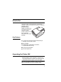
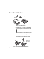
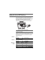
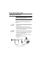
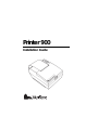
Printer 900
Installation Guide
Printer 900 Installation Guide
Table of Contents
Introduction ..............................................................................................................3
Key Features ....................................................................................................3
Unpacking the Printer 900.......................................................................................4
Setting the Internal DIP Switches ...........................................................................5
Switch 1 ............................................................................................................5
Switch 2 ............................................................................................................5
Switches 3 and 4..............................................................................................5
Installing the Printer 900 .........................................................................................6
Power Connection ............................................................................................6
Terminal Connection ........................................................................................6
Installing or Replacing the Ribbon Cartridge...................................................7
Installing the Paper Roll ...................................................................................8
Running the Print Test .................................................................................. 10
Removing the Paper Roll.............................................................................. 10
Cleaning................................................................................................................ 10
Printer Specifications............................................................................................ 11
Accessories............................................................................................................11
FCC Warning:
WARNING: This equipment has been tested and found to comply with the limits for a Class A digital device, pursuant to Part 15 of the FCC Rules. These units are designed to provide reasonable protection
against harmful interference when the equipment is operated in a commercial environment. This equipment generates, uses, and can radiate radio frequency energy and, if not installed and used in
accordance with the instruction manual, may cause harmful interference to equipment in a residential
area in which case the user will be required to correct the interference at his own expense.
Copyright 1995 VeriFone, Inc. All rights reserved.
No part of this publication may be copied, distributed, stored in a retrieval system, translated into any human or computer language, transmitted, in any form
or by any means, without the prior written consent of VeriFone, Inc.
VeriFone, ZON and TRANZ are registered trademarks of VeriFone, Inc.
Printer 900 is a trademark of VeriFone, Inc.
2
Introduction
The Printer 900 is a high-performance, freestanding
dot-matrix roll printer for VeriFone terminals or computers
equipped with an
RS-232 serial port.
Capable of printing up to
42 characters per line, it
is ideal for printing
receipts or data on one-,
two-, or three-ply
carbonless 76-mm wide
roll paper.
Key Features
•
3.7 lines per second with full line width printing at
9600 bps communication speed
•
High reliability
•
Double height, double width, and double
height/double width printing
•
Custom high-yield ribbon
•
Automatic paper feed
Unpacking the Printer 900
1. With the shipping carton right side up, open the carton’s lid and remove its contents. You should have the
components shown in Figure 2 on the next page.
Note: Save all packing material in case you ever have to
ship the Printer 900 or move it to another location.
3
Printer 900 Installation Guide
Ribbon Cartridge
Paper Roll
Power Supply
Printer 900
Figure 1. Printer 900 Components
2. Place the printer on a solid desk or table top. When
choosing a location for the printer, avoid areas with
•
direct sunlight or objects that radiate heat
•
excessive moisture
•
excessive dust
•
devices that cause excessive voltage fluctuations
or electrical noise such as air conditioners, fans,
electric motors or high frequency security devices.
3. Lift up the ribbon cover and remove the cardboard
spacer that protects the print head during shipment.
Save the spacer with the other packing material.
Cardboard
Spacer
Carefully remove
cardboard spacer
and save with
other packing
material.
Figure 2. Removing the Protective Cardboard Spacer
4
Setting the Internal DIP Switches
A set of four DIP switches is located under the paper
holder on the bottom of your Printer 900. Make sure that
these switches are set as indicated below before
connecting and operating the printer. The printer will not
operate properly if the switches are not set correctly.
ON
Figure 3. Location of DIP Switches
CAUTION: Always disconnect the power before changing
the DIP switch settings.
Refer to the table below for the proper DIP switch
settings. If you are not sure of which settings to use, refer
to the reference manual for your terminal or computer’s
application program.
Switch 1
Switch 2
Switches 3
and 4
Parity
Even Parity
Odd Parity
on
off
Word Length (data bits)
7 bit word
off
8 bit word
on
Baud Rate
1200
2400
4800
9600
(default setting)
(default setting)
(no parity)
Switch 3
Switch 4
on
on
off
off
on
off
on
off
(default setting)
5
Printer 900 Installation Guide
Installing the Printer 900
CAUTION: Unplug the terminal’s power pack before connecting the Printer 900 to the terminal.
Before installing the Printer 900, you must have the
correct printer interface cable. The Accessories Section,
located on the last page of this installation guide, lists the
interface cable part numbers for different VeriFone
terminals.
Power
Connection
1. Connect the 3-pin plug from the printer power supply to
the power connector on the right side of the Printer
900 rear panel.
2. Plug the Printer 900 power pack into an indoor,
grounded AC outlet. The printer will now be turned on
and will run through a power-up routine. Do not install
or operate the Printer 900 outdoors.
Terminal
Connection
3. Making sure that the arrow on the printer interface cable connector is up, carefully plug the 8-pin mini-DIN
connector into the communications port on the left
side of the Printer 900 rear panel.
4. Plug the other end of the cable into your terminal’s
RS-232 8-pin port.
5. Plug in the terminal’s power pack
(not shown).
Figure 4. Printer Connections
6
Installing or
Replacing the
Ribbon
Cartridge
1. Remove the ribbon cover by pressing the front tab and
lifting the cover up.
2. If you are replacing an old ribbon, pull up on the lift tab
on the right side of the cartridge (see Figure 6), remove
the cartridge and discard it.
3. Remove the new ribbon
cartridge from its protective packaging and insert it, left side first, into
the printer. Be sure the
round knob is facing up
and the ribbon fabric fits
between the print head
and the ribbon guide.
4. Press the right side of
the ribbon cartridge into
place (Figure 7). If it
Figure 6. Removing the
does not fit easily, lift
Ribbon Cartridge
the cartridge out and try
again. Do not force the
ribbon cartridge into place.
5. Turn the small
knob on the
cartridge clockwise to remove any
slack.
6. Insert the two
tabs on the
rear of the ribbon cover into
the slots on
the printer.
Ribbon
Cover
Figure 7. Replacing the Ribbon Cartridge
7. Press the front
of the cover
down and snap it into place.
7
Printer 900 Installation Guide
Installing the
Paper Roll
The Printer 900 accepts paper that is 76mm wide. There
are three different types of roll paper available from
VeriFone. These are listed in the Accessories Section on
page 11.
Note: For best results, be sure the leading edge of the
paper roll is cut cleanly rather than torn before feeding it
into the printer. This is particularly important when inserting multiple-part paper.
1. Remove the roll cover by pressing the tabs on both
sides of the paper cover and lifting the cover up.
Refer to Figure 8
on the next page
while performing
these steps.
2. Hold the paper roll at the front of the paper cavity, with
the paper roll facing you, unrolling from the bottom.
Slowly move the paper roll down and backwards, into
the cavity, until the paper support arms snap into the
paper roll core.
3. To engage the auto feed mechanism, take the end of
the paper roll and gently guide the paper end into the
paper feed path. The paper feed path is on the base
of the paper cavity in front of the paper roll. The paper
feed path is marked with an arrow. As soon as the
sensor detects the paper, the printer will automatically
feed and advance the paper.
4. Replace the roll cover onto the printer, sliding the front
edge of the cover behind the tear bar. Make sure that
the paper extends through the slot on top of the
printer, and then snap the roll cover into place.
CAUTION: If you must remove the paper roll, do not pull
the paper out from the back of the printer. This could
damage the feed mechanism. Instead, cut or tear the paper from the rear of the printer. Use the paper feed button to remove the stub remaining in the feed mechanism.
8
To engage the auto feed
mechanism, gently guide
paper end into paper
feed path. As soon as
the sensor detects the
paper, the printer
automatically feeds and
advances the paper.
Roll
Cover
Paper Feed
Path
Paper Cavity
Paper
Roll
Paper Roll Core
Paper Feed
Button
Paper Support
Arms
Figure 8. Installing the Paper Roll
(exploded view)
9
Printer 900 Installation Guide
Running the
Print Test
1. Disconnect the power cord at the rear of the printer.
2. Hold down the paper feed button and plug the power
cord back into the printer. Release the feed button when
printing begins. The printer will stop automatically after
printing 100 lines of the U.S. character set.
Removing the
Paper Roll
CAUTION: If you must remove the paper roll, do not pull
the paper out from the back of the printer. This could
damage the feed mechanism. Instead, cut or tear the paper from the rear of the printer. Use the paper feed button to remove the stub remaining in the feed mechanism.
Cleaning
CAUTION: Never use thinner, trichloroethylene, or ketone based solvents to clean the printer as they may deteriorate plastic parts.
1. Remove dirt using a clean cloth dampened with water
and mild soap. Remove stubborn stains with alcohol or
benzine.
2. If necessary use a small vacuum cleaner to remove paper particles and dust from the inside of the printer.
10
Printer Specifications
Power
Requirements
Dimensions
and Weight
Voltage:
90 VAC–137 VAC, 47–60 Hz
(low voltage version)
180 VAC–274 VAC, 47–60 Hz
(high voltage version)
Power consumption: 45W max @ 100VAC input;
0.5 Amp (average) @ 120 VAC input
Height:
Width:
Depth:
Shipping Weight:
Footprint:
94.5 mm (3.72 in.)
156.0 mm (6.1 in.)
238.0 mm (9.38 in.)
2.60 kg (5.75 lbs)
371.29 square cm (57.03 square in.)
11
Printer 900 Installation Guide
Accessories
VeriFone
Part No.
Description
Ribbon
Cartridges
CRM0023
CRM0025
Red/Black
Purple
Roll paper
CRM0008-01
CRM0008-02
CRM0008-03
Paper, 11 mm core 2-ply P250/500/900R
Paper, 11 mm core 3-ply P250/500/900R
Paper, 11 mm core 1-ply P250/500/900R
Supply Kit
25052-01
10 rolls of paper, 1 ribbon (red/black)
Interface
Cables:
The interface cables are listed here without length
specification (-XX suffix). Normally, a -00 suffix denotes a
1 meter length. For other lengths, contact your VeriFone
sales representative.
For ZON Jr XL, XL300, TRANZ 3xx, OMNI 3xx, ZON II
XPE*, and ZON II XJ* terminals:
10448-XX
with straight terminal connector
10454-XX
with 90-degree terminal connector
*Requires 10448-XX cable
For OMNI 4xx:
03015-XX
For ZON, ZON II:
10512-XX
VeriFone, Inc.
Technical Publications Dept
100 Kahelu Ave.
Mililani, HI 96789
Part Number 25015, Rev. B
12
February 1995
Printed on recycled paper.