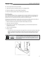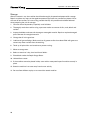
1
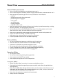
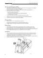
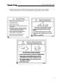
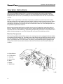
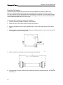
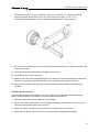
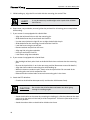
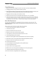
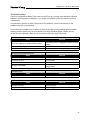
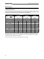
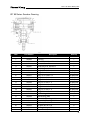
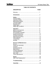
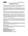
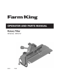
Operator and Parts Manual
Rotary Tiller
65 Series - 50", 60", 72" & 82"
082011
FK302
Table of Contents - 65 Series Rotary Tiller
Table of Contents
Introduction..................................................................................................................................5
Safety.............................................................................................................................................6
• Safety.................................................................................................................................6
• General Safety...................................................................................................................7
• Start-up Safety..................................................................................................................7
• Operation Safety...............................................................................................................7
• Transport Safety................................................................................................................7
• Service and Maintenance Safety.....................................................................................8
• Storage Safety...................................................................................................................8
• Safety Signs......................................................................................................................8
• Safety Sign Installation....................................................................................................8
Assembly.....................................................................................................................................10
• Assembly Instructions....................................................................................................10
Start-up.......................................................................................................................................10
• Machine Break-in............................................................................................................10
• Pre-operation Checklist................................................................................................... 11
Operation....................................................................................................................................12
• Machine Components.....................................................................................................12
• Equipment Matching......................................................................................................13
• Driveline Dimension.......................................................................................................14
• Attaching/Unhooking......................................................................................................15
• Field Operation................................................................................................................17
• Transporting....................................................................................................................19
• Storage............................................................................................................................20
• Theory of Operation.......................................................................................................21
Maintenance...............................................................................................................................22
• Service.............................................................................................................................22
• Fluids and Lubricants.....................................................................................................22
• Greasing..........................................................................................................................22
• Servicing Intervals..........................................................................................................23
• A-frame Adjustment.......................................................................................................24
• Time Replacement..........................................................................................................25
• Slip Clutch........................................................................................................................25
• Clutch Maintenance........................................................................................................26
3
Table of Contents - 65 Series Rotary Tiller
• Main Shaft Replacement................................................................................................26
• Troubleshooting..............................................................................................................27
Bolt Torque..................................................................................................................................28
• Checking Bolt Torque......................................................................................................28
Parts Drawings............................................................................................................................29
• Tiller Drawings................................................................................................................29
• Tiller Parts List.................................................................................................................32
• 50", 60", 72" & 82" PTO (Slip Clutch) Drawing..............................................................36
• 50", 60", & 72" PTO (Slip Clutch) Parts List....................................................................37
• 82" PTO (Slip Clutch) Parts List......................................................................................38
• 50", 60", & 72" 65 Series Gearbox Drawing and Parts List..........................................40
• 82" 65 Series Gearbox Drawing and Parts List.............................................................41
Shipping Kit and Bundle Numbers...........................................................................................42
Warranty......................................................................................................................................44
Manufacturer’s statement: for technical reasons Buhler Industries Inc. reserves the right to modify
machinery design and specifications provided herein without any preliminary notice.
Information provided herein is of descriptive nature. Performance quality may depend on soil fertility,
applied agricultural techniques, weather conditions and other factors.
4
Introduction - 65 Series Rotary Tiller
Introduction
Farm King has a collection of rotary tiller models to suit your garden and landscaping needs.
The 65 Series Tiller attaches to the 3-point hitch as well as Cat. 1 & 2 Quick Hitch, and is designed
to fit a variety of tractors, from 30 hp to 65 hp. Tilling widths range from 46" to 77" in the 65 Series.
The tilling shaft is equipped with five to eight flanges, depending on the model. Flanges on all
series are available with four tines, and six tines per flange are standard on the 65 series. This
provides an optimum balance between performance and durability, even in heavy soils and when
breaking untilled soil.
Standard on all Farm King Rotary Tillers, the skid shoes are adjustable so it is easy to set the
perfect tilling depth. The automatic chain tightener is standard on all models. This ensures
the chain remains tight even under the toughest tilling conditions. Housed within a sealed oil bath,
the chain tightener is designed to be reliable and maintenance-free. Getting close to the fences,
hedges or covering a tire track is easy with the side shift feature. The entire unit can be pushed to
one side, while the PTO shaft remains in line with the tractor to minimize stress on the universal
joint. The side shift feature is available on all Farm King Rotary Tillers except the C6582.
Keep this manual handy for frequent reference. All new operators or owners must review the
manual before using the equipment and at least annually thereafter. Contact your Farm King
Dealer if you need assistance, information, or additional copies of the manual. Visit our website at
www.buhlerindustries.com for a complete list of dealers in your area.
The directions left, right, front and rear, as mentioned throughout this manual, are as seen facing
in the direction of travel of the implement.
5
Safety - 65 Series Rotary Tiller
Safety
Safety Instructions
Remember, YOU are the key to safety. Good safety practices not only protect you, but also the
people around you. Make these practices a working part of your safety program. Be certain that
everyone operating this equipment is familiar with the recommended operating and maintenance
procedures and follows all the safety precautions. Most accidents can be prevented. Do not risk
injury or death by ignoring good safety practices.
The alert symbol is used throughout this manual. It indicates attention is required and identifies
hazards. Follow the recommended precautions.
The safety alert symbol means…
ATTENTION! BECOME ALERT! YOUR SAFETY IS INVOLVED!
6
Caution
The caution symbol indicates a potentially hazardous situation
that, if not avoided, may result in minor or moderate injury. It
may also be used to alert against unsafe practices.
Warning
The Warning Symbol indicates a potentially hazardous situation
that, if not avoided, could result in death or serious injury, and
includes hazards that are exposed when guards are removed. It
may also be used to alert against unsafe practices.
Danger
The Danger Symbol indicates an imminently hazardous situation
that, if not avoided will result in death or serious injury. This
signal word is to be limited to the most extreme situations,
typically for machine components that, for functional purposes,
cannot be guarded.
Safety - 65 Series Rotary Tiller
General Safety Instructions
• Have a first-aid kit available for use and know how to use it.
• Have a fire extinguisher available, stored in a highly visible location, and know how to use it.
• Wear appropriate protective gear. This list may include but is not limited to:
-- hard hat
-- protective shoes with slip resistant soles
-- protective glasses or goggles
-- heavy gloves
-- wet weather gear
-- hearing protection
-- respirator or filter mask
• Read and understand the Operator’s Manual and all safety signs before operating, servicing,
adjusting, repairing, or unplugging the equipment.
• Do not attempt any unauthorized modifications to your Farm King product as this could
affect function or safety, and could affect the life of the equipment.
• Never start or operate the mower except from the operator’s station on the power unit.
• Inspect and clean the working area before operating.
• Keep hands, feet, clothing, and hair away from moving parts.
• Ensure bystanders are clear of the area before operating.
Start-up Safety
•
•
•
•
•
•
Do not let inexperienced operators or children run this equipment.
Place all tractor and machine controls in neutral before starting.
Operate only with ROPS and seatbelt equipped tractors.
Do not operate inside a building unless there is adequate ventilation.
Ensure all shields are in place and in good condition before operating.
Stay clear of PTO shaft and machine when engaging PTO.
Operation Safety
•
•
•
•
Do not permit riders.
Do not wear loose fitting clothing during operation.
Never operate over 540 PTO rpm speed.
Never operate the equipment in the raised position.
Transport Safety
• Review Transport Safety instructions in tractor manual before moving.
• Check with local authorities regarding transport on public roads. Obey all applicable laws
and regulations.
• Make sure the SMV (Slow Moving Vehicle) emblem and all the lights and reflectors that are
required by the local highway and transport authorities are in place, are clean, and can be
seen clearly by all overtaking and oncoming traffic.
• Never have the equipment in operation during transport.
• Always travel at a safe speed.
7
Safety - 65 Series Rotary Tiller
Service and Maintenance Safety
• Stop engine, set brake, remove ignition key, and wait for all moving parts to stop before
servicing, adjusting, repairing, or unplugging.
• Support the equipment with blocks or safety stands before working beneath it.
• Follow good shop practices including:
-- keep service area clean and dry
-- be sure electrical outlets and tools are properly grounded
-- use adequate light for the job.
• Use only tools, jacks, and hoists of sufficient capacity for the job.
• Replace and secure all shields removed during servicing before operating.
• Use heavy leather gloves to handle sharp objects.
Storage Safety
• Store the unit in an area away from human activity.
• Do not permit children to play on or around the stored machine.
• Support the frame on stands and blocks to provide a secure base.
Safety Signs
• The following illustration shows the approximate location and detail of safety signs.
• Keep all safety signs clean and legible and replace any that are damaged or missing.
• When original parts are replaced, any safety signs affixed to those parts should be replaced
as well. Replacement safety signs are available from your local dealer.
Installation
• To install safety signs, ensure the installation area is clean and dry. Decide on the exact
position before you remove the backing paper. Remove the smallest portion of the split
backing paper and align over the specified area. Carefully press in place.
• Slowly peel back the remaining paper and smooth the remaining portion in place. Small air
pockets can be pierced with a pin and smoothed out.
8
Safety - 65 Series Rotary Tiller
• Replace safety signs immediately should they become damaged, torn or illegible.
Obtain replacements from your authorized dealer using the part numbers shown.
B
A
C
9
Assembly / Start-up - 65 Series Rotary Tiller
Assembly Instructions
The machine is shipped with the PTO shaft not installed.
To install the PTO driveline on the machine, follow this procedure.
1. Clear the area of bystanders, especially small children.
2. Clean the splines on the yoke and the input shaft.
3. Align the splines on the yoke and the shaft.
4. Attach the driveline to the tiller by removing the tapered pin and sliding the yoke onto the
gearbox shaft. Line up the pin with the groove in the gearbox shaft and fasten with the tapered
pin. The plastic gearbox PTO guard has a removable door on top to access the pin. The A-frame
brace can be removed to improve accessibility. Replace the brace after tightening the nut on
the tapered pin.
5. Be sure the yoke is locked in position. Pull on the yoke to be sure the pin clicks into position.
6. Be sure that the PTO shaft is the appropriate length for the tractor/Tiller combination. Refer to
Driveline Dimension Section for details.
Start-up
Machine Break-in
Although there are no operational restrictions on the Tiller when used for the first time, it is
recommended that the following mechanical items be checked:
• After operating for 1/2 hour or after completing 1/2 acre:
-- Check all nuts, bolts and other fasteners. Tighten to their specified torque level.
-- Check that the blades are in good condition and bolted securely to the rotor.
-- Check the oil level in the gearbox. Add as required.
-- Check that the PTO driveline shield turns freely.
-- Lubricate all grease points.
• After operating for 5 hours and 10 hours:
-- Repeat the items above.
-- Then go to the regular service schedule as defined in Section 5.
10
Start-up - 65 Series Rotary Tiller
Pre-operation Checklist
Efficient and safe operation of the Rotary Tiller requires that each operator reads and understands
the operating procedures and all related safety precautions outlined in this section. A pre-operation
checklist is provided for the operator. It is important for both personal safety and maintaining the
good mechanical condition of the Tiller that this checklist is followed.
• Before operating the machine and each time thereafter, the following areas should be checked
off:
□□ Lubricate the machine per the schedule outlined in the Service and Maintenance Section.
□□ Use only a tractor of adequate power and weight to pull the machine.
□□ Check that the machine is properly attached to the tractor. Be sure retainers are used on the
mounting pins.
□□ Check the oil level in the gearbox. Add as required.
□□ Check that the PTO driveline shield turns freely and that the driveline can telescope easily.
Clean and lubricate if required.
□□ Check the blades. Be sure they are not damaged or broken and are bolted securely to the
rotor. Repair or replace as required.
□□ Remove any entangled material on rotating parts.
□□ Install and secure all guards, doors and covers before starting.
□□ The four socket set screws on the inside of the PTO clutch assembly must be turned out as far
as they go to engage the clutch.
11
Operation - 65 Series Rotary Tiller
Operation Instructions
The Farm King 65 Series Rotary Tiller is a machine that combines the primary and secondary
tillage operation into one machine. It breaks up the soil and prepares the seed bed in one pass.
Rotational power to the rotor is provided by the tractor PTO. Be familiar with the machine before
starting.
NOTE: It is the responsibility of the owner or operator to read this manual and to train all other
operators before they start working with the machine. Follow all safety instructions exactly. Safety
is everyone's business. By following recommended procedures, a safe working environment is
provided for the operator, bystanders and the area around the work site. Untrained operators are
not qualified to operate the machine.
Many features incorporated into this machine are the result of suggestions made by customers
like you. Read this manual carefully to learn how to operate the machine safely and how to set it
to provide maximum field efficiency. By following the operating instructions in conjunction with a
good maintenance program, your Tiller will provide many years of trouble free service.
Machine Components
The Farm King 65 Series Rotary Tiller consists of a rotating drum that is equipped with bent blades
for breaking up and leveling soil. The blades are turned through the soil while the machine moves
over the working area. A Drag Shield is used to maintain a level seedbed. Rotational power to the
drum is provided by the PTO on the tractor. The power is transmitted through the gearbox in the
center of the machine to the chain drive down the side. The A-frame can be moved to offset the
machine.
A - Point A-frame
B - PTO Driveline
C - Gear Box
D - Chain Drive
E - Rotor
F - Blades
G - Skid Plates
12
Operation - 65 Series Rotary Tiller
Equipment Matching
To insure the safe and reliable operation of the Tiller, it is necessary to use a tractor with the correct
specifications. Use the following list as a guide in selecting a tractor to use on the machine.
1. Horsepower: Use Table 1 as a guide in selecting the tractor horsepower appropriate for your
width of machine. Use only small Agricultural tractors on this machine.
Table 1 - Horsepower vs. Width
Model
Width
Horsepower
50H
4.2 ft (1.3 m)
40
60H
5 ft (1.5 m)
45
72H
6 ft (1.8 m)
55
82H
7 ft (2.1 m)
65
Alert
Do not exceed the recommended horsepower levels. The use of
horsepower will void the warranty.
2. Tractor Weight: By following the recommendations for the tractor power, the tractor will have
sufficient weight to provide stability for the unit during field operation or when transporting. It
is also recommended that each tractor be equipped with a full complement of suitcase weights
on the front of the tractor. This will provide the required weight on the front for turning and
extra traction if equipped with front wheel assist.
3. 3- Point Hitch: The Tiller is equipped with a Category 1, 3-point hitch. Be sure the tractor
3-point hitch is in the Category 1 configuration. Install the lift arm blocks or shorten the stop
chains to place the arms into the non-sway configuration. Refer to the tractor manual for
details.
4. Load Sensing Hydraulics: Many newer tractors are equipped with “Load Sensing” hydraulics.
It is the responsibility of the operator to set the tractor hydraulic system to provide “float” on
the 3-point hitch. Refer to Tractor Manual for details. The float feature will allow the machine to
follow the ground contours during operation.
5. PTO Shaft: The tractor must have a 1-3/8" 6 spline 540 rpm PTO shaft to fit the driveline shaft
supplied with the machine. Do not use shaft adapters or operate at any other speed. It is
not recommended that a tractor with variable speed PTO’s be used on the Tiller. Operating at
speeds faster than 540 rpm will overload the drivetrain and lead to early failures.
Attach the safety chains supplied with the PTO shaft, allowing sufficient slack for the driveline
during turns and operation. Check booklet attached to the PTO for instructions.
13
Operation - 65 Series Rotary Tiller
Driveline Dimension
A PTO driveline is supplied with the machine. To accommodate the variety of 3-point hitch
geometry available today, the driveline can be too long for some machines and must be cut.
It is very important that the driveline be free to telescope but not bottom out when going through
its working range. If the driveline bottoms out, the bearings on both the machine and tractor PTO
shaft will be overloaded and fail in a short time.
If cutting the drive is necessary, follow this procedure:
1. Clear the area of bystanders, especially small children.
2. Attach the Tiller to the tractor but do not attach the driveline.
3. Raise the implement until the input gearbox shaft is at the closest point to the tractor output
shaft.
4. In this position, measure the dimension between the locking groove on the tractor output shaft
and the groove on the Tiller input shaft.
5. Measure the pin to pin dimension on the compressed driveline.
6. If the driveline pin to pin dimension (B) exceeds the groove to groove dimension, the driveline
should be cut.
14
Operation - 65 Series Rotary Tiller
7. To determine how much to cut off the PTO shaft ends, calculate “X” using the following
formulas and the dimensions “A” and “B” from the previous steps. X = B – A + ½”.
Pull the driveline apart and cut off the dimension determined “X” from each end.
8. Be sure to use a hacksaw to cut from each end of the separated shaft. Cut both the plastic tube
and the metal cores.
9. Use a file to remove the burrs from the edges that were cut.
10. Assemble the two ends of the shaft.
11. Make sure that the shaft can telescope freely. If it does not, separate the two parts and inspect
for burrs or cuttings on the shaft ends. Be sure it telescopes freely before installing.
12. Make sure the plastic covering shield is free to rotate on the shaft before installing on the
machine.
Attaching/Unhooking
The Tiller should always be located on a level, dry area that is free of debris and other foreign
objects. When attaching the machine to a tractor, follow this procedure:
1. Clear the area of bystanders, especially small children.
2. Be sure the tractor 3-point hitch is in the Category 1 configuration and the lift arms are in the
non sway configuration (See tractor manual).
3. Make sure there is enough room and clearance to safely back up to the Tiller.
4. Attach the PTO driveline to the Tiller if it was removed for storage (See Assembly).
15
Operation - 65 Series Rotary Tiller
5. While backing up, align the lift arm balls with the mounting pins on the Tiller.
Alert
It may be necessary to add weight to the 3-point hitch to lower
the lift arms.
6. Stop tractor, set park brake, remove ignition key and wait for all moving parts to stop before
dismounting.
7. If your tractor is not equipped with a Quick Hitch:
-- Align the left lower link arm with the mounting pin.
-- Slide the ball over the pin and install the Linch Pin.
-- Use the screw jack on the right lift arm to align the ball with the pin.
-- Slide the ball over the mounting pin and install the Linch Pin.
-- Level the frame using the screw jack.
-- Remove retainer and pin from the mast.
-- Align top link using the turnbuckle.
-- Insert pin and install Linch Pin
-- Level frame using the turnbuckle.
8. If your tractor is equipped with a Quick Hitch:
-- Set the height of the 3-point hitch so the Quick Hitch claws are lower than the mounting
pins.
-- Be sure the 3 point hitch is set in the non-sway position (See tractor manual for details.)
-- Align the claws under the mounting pins while backing up.
-- When the claws are under the pins, slowly raise the 3 point hitch. Be sure each of the
mounting pins seat in their respective claw.
-- Release the claw retainer locks to secure the mounting pins in the claws.
9. Attach the PTO driveline:
-- Check that the driveline telescopes easily and that the shield rotates freely.
Caution
Be sure that the driveline does not bottom out when going
through its working angles.
-- Attach the driveline to the tractor by retracting the locking pin, slide the yoke over the shaft
and push on the yoke until the lock pin clicks into position. Pull on the yoke to be sure it is
locked in position.
-- Attach the anchor chain on the driveline shield to the frame.
16
Operation - 65 Series Rotary Tiller
10. Use the 3-point hitch to raise the machine.
11. Unpin the front frame stand. Raise and pin in its storage position.
12. Remove the blocks from under the Depth Gauge Shoes.
13. Reverse the above procedure when unhooking from the tractor.
Field Operation
Farm King 65 Series Rotary Tillers are designed with the inherent flexibility of operating well in
almost any kind of soil and terrain conditions. However, the operator has the responsibility of
being familiar with all operating and safety procedures and following them.
Each operator should review this section of the manual at the start of the season and as often as
required to be familiar with the machine. When using, follow this procedure:
1. Review and follow the pre-operation checklist. Review Safety Instructions.
2. Attach the tractor to the machine.
3. Before going to the field review Transporting Section, pull into the field and position the
machine in a level area.
4. Lower into working position.
5. Set the machine.
-- Level the frame: Use the screw jack on the right lift arm to level the frame from side to side.
-- Depth: Use the Depth Gauge Shoes on each side to set the operating depth. Position the
Depth Gauge Shoes in the top hole for shallow tilling and in the bottom hole for deep
tilling.
Alert
In soft soil conditions, the skid plates become less effective and
sink into the ground. Use the turnbuckle on the top link to set the
frame angle so the bottom of the Depth Gauge Shoes are level
when operating.
17
Operation - 65 Series Rotary Tiller
-- Offset: The Category Pin Brackets can be moved 3" to 4" along the Deck Assembly to either
side of center if required. Center the machine for normal operation. Offset if the tire tracks
are wider than the machine or when tilling around trees, bushes or other areas.
Alert
Sliding offset feature not available in the 82" model.
-- Drag Shield: Adjust the chain in the Adjustment Bracket to set the height of the Drag Shield.
Set the Drag Shield to just contact the tilled soil when operating.
6. Align the unit with the working area.
7. Starting Machine:
-- Run the engine at low idle
-- Slowly engage the PTO control to start the machine.
-- Slowly bring the engine to the rated PTO speed. Never exceed rated speed.
-- Lower the machine to the ground and proceed down the field.
8. Stopping Machine:
-- Slowly decrease engine speed to low idle.
-- Raise machine out of the ground.
-- Disengage PTO clutch slowly.
Caution
Place all controls in neutral, lower machine, stop engine, set park
brake, remove ignition key and wait for all moving parts to stop
before dismounting.
9. Ground Speed: Travel speed can vary between 2 and 5 mph (3 and 8 km/h) depending on the
soil and terrain conditions. It is the responsibility of the operator to note the condition of the job
being done and set the speed to obtain a quality tilling job and maintain control of the machine.
The speed can be increased to optimize tilling. Decrease speed if you want the soil worked to a
finer texture.
10. Operating Hints:
-- Determine the moisture content of the soil before starting. Soil that is too wet will “ball-up”
in the rotor blades making tilling impossible. Sandy soils normally can be worked better
than heavy clay or loam soils. It is the responsibility of the operator to determine the soil
type and moisture content before starting. It may be necessary to wait for the soil to dry
out before starting to work.
-- Set the length of the Top Link to obtain the quality of the job desired without needlessly
using power and fuel in churning the soil. Use the condition of the seedbed as your guide.
18
Operation - 65 Series Rotary Tiller
-- When tilling hard or compacted soils, it is recommended that two passes be used when
working. Use the Depth Gauge Shoes on each side of the frame to adjust the tilling
depth of the machine. The second pass should be made at an angle to the first to give a
consistent job and minimize compaction.
-- Always remove heavy crop cover, all grass and weeds, before starting to prevent rotor
plugging.
-- The rotation of the Tines propel the machine in the forward direction. Always use the
tractor transmission to control the speed of forward travel.
-- Always disengage the PTO control and raise the machine out of the ground before
depressing the master clutch on the tractor.
-- Use low gear on the tractor to start the job. Increase the speed of forward travel only as the
quality of the job and power available will allow.
-- If the slip clutch slips, reduce the ground speed or raise the machine slightly out of the
ground.
Transporting
When transporting the machine, review and follow these instructions:
1. Be sure all bystanders are clear of the machine.
2. Be sure that the machine is securely attached to the tractor and all retainer pins are installed.
3. Clean the SMV emblem, lights and reflectors and be sure they are working.
4. Be sure you are in compliance with all applicable lighting and marking regulations when
transporting. Check with your local authorities.
5. Be sure your machine can clearly be seen by overtaking and oncoming traffic.
6. Keep to the right and yield the right of way to allow faster traffic to pass. Drive on the road
shoulder if permitted by law.
7. Do not allow riders.
8. Always use hazard flashers on the tractor when transporting unless prohibited by law.
9. Use pilot vehicles front and rear when transporting during times of limited visibility.
10. Never transport the machine faster than 20 mph (32 km/h). The ratio of the tractor weight
to the Tiller weight plays an important role in defining acceptable travel speed. Table 2
summarizes the recommended travel speed to weight ratio.
Table 2 - Speed vs. Weight Ratio
Road Speed
Weight of fully equipped or loaded implement(s)
relative to weight of towing machine
Up to 20 mph (32 km/h)
1 to 1, or less
Up to 10 mph (16 km/h)
2 to 1, or less
Do not tow
More than 2 to 1
19
Operation - 65 Series Rotary Tiller
Storage
After the season's use, the machine should be thoroughly inspected and prepared for storage.
Repair or replace any worn or damaged components to prevent any unnecessary down time at
the start of next season. To insure a long, trouble free life, this procedure should be followed
when preparing the unit for storage:
1. Clear the area of bystanders, especially small children.
2. Thoroughly wash the machine using a pressure washer to remove all dirt, mud, debris and
residue.
3. Inspect the blades and rotors for damage or entangled material. Repair or replace damaged
parts. Remove all entangled material.
4. Change the oil in the gear box.
5. Lubricate all grease fittings. Make sure that all grease cavities have been filled with grease to
remove any water residue from the washing.
6. Touch up all paint nicks and scratches to prevent rusting.
7. Move to storage area.
8. Select an area that is dry, level and free of debris.
9. Place blocks under the Depth Gauge Shoes.
10. Unhook from tractor.
11. If the machine cannot be placed inside, cover with a waterproof tarpaulin and tie securely in
place.
12. Store the machine in an area away from human activity.
13. Do not allow children to play on or around the stored machine.
20
Operation - 65 Series Rotary Tiller
Theory of Operation
21
Maintenance - 65 Series Rotary Tiller
Maintenance
Service
Follow Maintenance Safety Instructions as outlined.
Fluids and Lubricants
1. Hydraulic Oil:
-- Use standard hydraulic oil for all operating conditions.
2. Gear Box Oil:
-- Use an SAE 85W90 gear oil for all operating conditions.
-- Gear Box Capacity: 1 U.S. quart (0.85 liter)
3. Chain Case Grease:
-- Use a multi purpose grease for all operating conditions.
-- If chain case is removed, refill with 800 grams of grease.
4. Storing Lubricants:
-- Your machine can operate at top efficiency only if clean lubricants are used. Use clean
containers to handle all lubricants. Store them in an area protected from dust, moisture
and other contaminants.
Greasing
Use a Maintenance Checklist to keep a record of all scheduled maintenance.
1. Use a hand held grease gun for all greasing.
2. Wipe grease fitting with a clean cloth before greasing, to avoid injecting dirt and grit.
3. Replace and repair broken fittings immediately.
4. If fittings will not take grease, remove and clean thoroughly. Also clean lubricant passageway.
Replace fitting if necessary.
22
Maintenance - 65 Series Rotary Tiller
Servicing Intervals
If fittings will not take grease, remove and clean thoroughly. Also clean lubricant passageway.
Replace fitting if necessary.
8 Hours or Daily: Telescoping Tubes and Quick Disconnect 20 Hours
1. Lubricate PTO driveline (7 locations).
Alert
When using the safety chains supplied with the PTO shaft,
the shield bearings must be kept lubricated.
80 Hours or Once a Season:
2. Lubricate rotor driven end bearing (1 location)
3. Lubricate rotor drive end bearing (1 location).
4. Lubricate chain drive bearing (1 location).
-- use 3 squirts only.
-- push grease in gradually
23
Maintenance - 65 Series Rotary Tiller
40 Hours
1. Check gearbox oil level.
-- add as required.
2. Add approximately 10 squirts of grease in chain case.
Annually
1. Change gear box oil. Refill with SAE 85W90 gear oil.
2. Wash machine.
A-frame Adjustment
When moving the hitch along the front frame to adjust the offset, follow this procedure.
1. Clear the area of bystanders, especially small children.
2. Raise the machine so it is slightly out of the ground.
3. Loosen the u-bolts through the Category Pin brackets.
4. Slide the hitch along the Deck until the machine is set at the desired offset.
5. Tighten the u-bolts to their specified torque.
24
Maintenance - 65 Series Rotary Tiller
Tine Replacement
When the Tines are damaged in any way, they will need to be replaced. When replacing, follow this
procedure:
1. Raise the machine until the Tines are slightly above the ground.
2. Stop engine, set park brake, remove ignition key and wait for all moving parts to stop before
dismounting.
3. Place blocks under each Depth Gauge Shoe to support the machine.
4. Raise the Drag Shield and secure in the up position.
5. Wear leather or heavy canvas gloves when handling Tines.
6. Remove mounting bolts from Tines.
Alert
An alternate method would be to disconnect the machine from
the tractor and tip it forward on its nose.
7. Install a new replacement blade and tighten the mounting bolts to their specified torque.
8. Lower the rear gate.
9. Remove the blocks under the skid plates.
Slip Clutch
During normal operation, the slip clutch can release and slip when encountering an obstruction or
when overloaded. It is designed to slip when the load exceeds 3 times its nominal rating. When the
clutch slips too frequently during normal operating conditions, it is necessary to replace the clutch
linings. NOTE: The PTO shafts are shipped with the slip clutch disengaged. There are four socket set
screws on the inside of the clutch assembly, which are turned out as far as they go to engage the
clutch. Disengage clutch by turning set screws in fully.
To replace clutch linings, follow this procedure:
1. Disengage the clutch by turning the four set screws all the way in.
2. Remove the outside bolts from the clutch assembly and replace the clutch linings.
3. When re-tightening the bolts, stop when the clutch spacer starts to touch the clutch plates. You
should be able to just move the spacer by hand when you have the correct bolt torque.
4. Engage clutch by turning out set screws after assembly is complete.
25
Maintenance - 65 Series Rotary Tiller
Clutch Maintenance
1. Before first use or after storage of more than one month, the clutch should be checked.
2. Disengage clutch by turning in the four socket set screws.
3. Run the PTO at low idle to slip the clutch linings. This will help remove the dirt, corrosion, and
surface gloss from the clutch plates and also ensure that the linings are loose.
4. Engage the clutch by turning out the socket set screws.
5. Normally the clutch will slip at a 20% higher torque after the “run in” than before.
6. Check the temperature of the clutch after running for 20 minutes and every 8 hours after that.
If the clutch is hot to the touch or smokes, check that the outside bolts are correctly tightened
as explained in slip clutch section. If clutch still slips, linings may have to be replaced.
Main Shaft Replacement
The main shaft is designed with a replaceable Final Drive Assembly on the driven end. This
feature keeps the cost of repairs down should replacement be required and makes main shaft
replacement easier.
When replacing the Final Drive Assembly, follow this procedure:
1. Clear the area of bystanders, especially small children.
2. Unhook from the tractor.
3. Remove the driveline and store to the side.
4. Remove the chain cover, the chain and the sprocket.
5. Use 2 people or a hoist to tip the machine forward on its nose.
6. Life the Drag Shield up and lay forward.
7. Remove the mounting bolts connect the Main Shaft to the Final Drive Assembly.
8. Wear leather or heavy canvas gloves when handling the Main Shaft and Tines.
9. Remove the Final Drive Assembly from the machine.
10. Install the replacement part.
11. Install and tighten the connecting bolts to their specified torque.
12. Install the sprocket and chain.
13. Tip the machine into the upright position.
14. Refill the chain cover with approximately 800 grams of multi-purpose grease.
15. Use gasket compound and replace the chain cover.
16. Be sure all fasteners are tightened to their specified torque.
26
Maintenance - 65 Series Rotary Tiller
Troubleshooting
The Farm King 65 Series Rotary Tiller moves curved Tines on a turning rotor through the ground
to break it up and prepare a seed bed. It is a simple and reliable system that requires minimal
maintenance.
In the following section, we have listed many of the problems, causes and solutions to the
problems that you may encounter.
If you encounter a problem that is difficult to solve, even after having read through this trouble
shooting section, please call your local Buhler Farm King distributor dealer. Before you call,
please have this Operator's Manual and the serial number from your Tiller ready.
Rotor won't turn
Cause
Solution
Slip clutch slipping or replace friction plates.
Check that clutch is engaged or replace friction
plates.
PTO clutch slipping.
Set PTO clutch. See tractor manual.
Broken drive chain.
Repair or replace chain.
Untilled ground behind machine
Cause
Solution
3-point hitch system not set.
Set 3-point hitch in float. See tractor manual.
Travelling too fast.
Travel slower
Ground very hard.
Slow down. Make 2 passes.
Machine not leveled.
Adjust screw jack on 3-point arm. Adjust Depth
Gauge Shoes.
Seed bed lumpy
Cause
Travelling too fast.
Solution
Slow down. Make 2 passes.
Uneven seed bed
Cause
Solution
Machine not level.
Level machine.
Drag Sheild too high.
Adjust Drag Sheild.
27
Bolt Torque - 65 Series Rotary Tiller
Bolt Torque
Checking Bolt Torque
The tables shown below give correct torque values for various bolts and hex bolts. Tighten all bolts
to the torques specified in chart unless otherwise noted. Check tightness of bolts periodically, using
bolt torque chart as a guide. Replace hardware with the same strength bolt.
Bolt Torque*
Bolt Diameter
Grade 2 Bolts
Grade 5 Bolts
Grade 8 Bolts
(inches)
SAE 2
SAE 5
SAE 8
“A”
(lb-ft)
(N.m)
(lb-ft)
(N.m)
(lb-ft)
(N.m)
0.25 (1/4)
6
8
9
12
12
17
0.313 (5/16)
10
13
19
25
27
36
0.375 (3/8)
20
27
33
45
45
63
0.438 (7/16)
30
42
53
72
75
100
0.5 (1/2)
45
61
80
110
115
155
0.563 (9/16)
70
95
115
155
165
220
0.625 (5/8)
95
128
160
215
220
305
.75 (3/4)
165
225
290
390
400
540
0.875 (7/8)
170
230
420
570
650
880
1
225
345
630
850
970
1320
Torque figures indicated above are valid for non-greased or non-oiled threads and heads unless otherwise
specified. Therefore, do not grease or oil bolts or hex bolts unless otherwise specified in this manual. When
using locking elements, increase torque values by 5%.
* Torque value for bolts and hex bolts are identified by their head markings.
28
Parts - 65 Series Rotary Tiller
50", 60" & 72" Series Drawing
29
Parts - 65 Series Rotary Tiller
50", 60" & 72" 65 Series Drawing
30
Parts - 65 Series Rotary Tiller
82" 65 Series Only Drawing
31
Parts - 65 Series Rotary Tiller
When Ordering Parts
Always give your dealer the Model, Color and Serial Number of your machine to assist him in
ordering and obtaining the correct parts. Use the exploded view and tabular listing of the area of
interest to exactly identify the required part.
Item
Part Number
1
906904
Chain Guard
2
967164
Pound-In Grease Fitting
3
912300171
4
959221
Bottom Sprocket Spacer 3-1/2"OD x 1.07"
100B16 Sprocket
5
81592
3/8" Hex Nut
6
903193
Cat. Pin Bracket Weldment - Right
7
906312
100H Roller Chain (38 Link w/ Connector)
8
912301557
1-5/8" Retainer Ring
9
912300170
100B11 Sprocket
10
912301556
1-3/4" Retainer Ring
11
982000500
Side Stand Weldment
12
912301660
Snapper Clip
13
982006422
1-5/8" Oil Seal Plate
14
967363
1-5/8" Four Bolt Flange Bearing
967364
1-5/8" Bearing Only
15
967361
7/8" x 4" Clevis Pin
16
965911
7/16" Linch Pin
17
906297
Deck Weldment (50")
906298
Deck Weldment (60")
906299
Deck Weldment (72")
906300
Deck Weldment (82")
959227
1-5/8" Hex Shaft (50")
959228
1-5/8" Hex Shaft (60")
959229
1-5/8" Hex Shaft (72" & 82")
19
84268
5/8" x 1-1/2" Hex Bolt (pl)
18
20
967372
5/8" U-Bolt
21
903171
Spacer 1.05" OD x 2-1/4"
22
982505211
Drive Shaft Shield (50")
982605211
Drive Shaft Shield (60")
982725211
Drive Shaft Shield (72")
982505311
Drive Shaft Shield (50")
982605311
Drive Shaft Shield (60")
982725311
Drive Shaft Shield (72")
24
982825212
Drive Shaft Shield (82")
25
F0354
PTO Shaft w/ Slip Clutch (50", 60", & 72")
F0355
PTO Shaft w/ Slip Clutch (82" only)
23
32
Description
Parts - 65 Series Rotary Tiller
Item
Part Number
26
967392
Description
Gearbox PTO Guard (50", 60", & 72")
912300160
Gearbox PTO Guard (82")
27
982005111
Drive Shaft Shield Mount
28
967558
912300159
S4073 Gearbox (50", 60", & 72")
4083 F Gearbox (82" only)
29
903320
Drive Shaft Shield (50", 60", & 72")
30
982825221
31
968632
1-1/2" - Four Bolt Flange Bearing
967295
1-1/2" Bearing only (Greasable)
Drive Shaft Shield (82")
32
982000350
Left Depth Gauge Shoe Weldment
33
982000300
Right Depth Gauge Shoe Weldment
34
982006400
Right Shaft Cover Cone
35
982506200
Main Shaft - 6 Tine (50")
982606200
Main Shaft - 6 Tine (60")
982726200
Main Shaft - 6 Tine (72")
967421
Main Shaft - 4 Tine (50")
967422
Main Shaft - 4 Tine (60")
967423
Main Shaft - 4 Tine (72")
982826200
Main Shaft - 6 Tine (82")
967424
Main Shaft - 4 Tine (82")
36
81593
3/8" Lock Washer
37
982000471
1/4" x 14 Link Chain
38
967357
Drag Shield Lift Bracket
39
903187
Cat. Pin Bracket Weldment - Left
40
909715
Drag Shield Hinge Rod (50'')
909712
Drag Shield Hinge Rod (60'')
909716
Drag Shield Hinge Rod (72'')
41
42
909717
Drag Shield Hinge Rod (82'')
967379
Final Drive Assembly - 6 Tine
967420
Final Drive Assembly - 4 Tine
909733
Drag Shield (50")
909734
Drag Shield (60")
909735
Drag Shield (72")
909736
Drag Shield (82")
43
967485
Tine Right
44
967486
Tine Left
45
982006322
46
959220
Top Sprocket Spacer 3"OD x 1.07"
47
48
1-3/4" Oil Seal Plate (6-1/2" x 6-1/2")
967374
2" Four Bolt Flange Bearing
967375
2" Bearing only
967393
Left Bearing Cover Cone
33
Parts - 65 Series Rotary Tiller
34
Item
Part Number
49
912303600
Description
1-3/4" Oil Seal
50
912303601
1-5/8" Oil Seal
51
982000341
Depth Gauge Shoe Bracket
52
907306
53
982005711
54
967378
Chain Tensioner Weldment
LH Side Plate Assy
Tension Spring
55
81525
1/4" x 3/4" Hex Bolt
56
84498
1/4" Lock Nut
57
81627
1/2" x 3" Hex Bolt
58
81637
1/2" Lock Washer
59
81636
1/2" Hex Nut
60
967122
5/8" x 2-1/4" Hex Bolt Grade 8
61
812482
5/8" Lock Nut
62
84270
5/8" x 1-3/4" Hex Bolt
63
812763
1/2" x 1-1/2" Hex Bolt Grade 8 (NF)
64
812764
1/2" x 2" Hex Bolt Grade 8 (NF)
65
812765
1/2" Hex Nut Grade 8 (NF)
66
81659
5/8" x 1" Hex Bolt (NC)
67
81677
5/8" Lock Washer
68
84277
1/2" x 1-1/2" Hex Bolt
69
812364
1/2" Lock Nut
70
86171
3/8" x 1-1/4" Hex Bolt
71
84000
3/8" B.S. Flat Washer
72
84072
3/8" x 3/4" Hex Bolt
73
812363
3/8" Lock Nut
74
81549
5/16" x 3/4" Hex Bolt
75
81569
5/16" Lock Washer
76
9812767
1/2" Lock Washer Grade
77
965807
Cat. 1 Top Link Pin
78
81676
5/8" Hex Nut
79
84048
1/2'' Flat Washer
80
81620
1/2" x 1-1/4" Hex Bolt
81
86170
3/8" x 1" Hex Bolt
82
903175
A-Frame Bottom Weldment
83
903179
A-Frame Top - Right Hand
84
903180
A-Frame Top - Left Hand
85
903181
A-Frame Brace Plate
86
811790
3/4" x 4-1/2" Hex Bolt
87
81700
3/4" Hex Nut
88
81701
3/4" Lock Washer
89
87553
1/2" x 1-3/4" Hex Bolt
Parts - 65 Series Rotary Tiller
Item
Part Number
90
81568
Description
5/16" Hex Nut
91
909277
Manual Holder
92
9812432
1-1/4'' Cotter Pin
93
812026
5/16" x 1" Hex Bolt
35
Parts - 65 Series Rotary Tiller
50", 60", 72" & 82" PTO (Slip Clutch) Drawing
36
Parts - 65 Series Rotary Tiller
Item
Part Number
Description
50", 60", & 72" PTO (Slip Clutch) Parts List
F0354
Shaft Complete
908262
Outer Half Shaft - Tractor
936527
Inner Half Shaft - Implement
1
908259
Quick Disc Yoke - RS
2
966236
Repair Kit
3
936352
Outer Tube Yoke
4
936358
Flexible Pin
5
936368
Outer Cardan Tube
6
936369
Inner Cardan Tube
7
936359
Flexible Pin
8
936353
Inner Tube Yoke
9
936564
Torque Limit
10
966234
Outer Shield Collar
11
966232
Outer Shield Cone Set
12
936370
Outer Shield Safety Tube
13
936371
Inner Shield Safety Tube
14
936518
Inner Shield Cone Set
15
966235
Inner Shield Collar
16
907192
Ball & Collar Kit
17
910-075
Taper Pin Kits
18
936524
Spring Set
19
936520
Clutch Plate
20
936521
Clutch Lining
21
936523
Hub C/W Q.D.
22
936522
Thrust Plate
23
936519
Clutch Screw
24
936402
Complete Safety Chain
25
966223
Antifriction Sleeve
26
936526
Spacer
27
936512
Set Screw
NOTE: Set Screw should be backed out all the way to engage clutch.
37
Parts - 65 Series Rotary Tiller
Item
Part Number
Description
82" PTO (Slip Clutch) Parts List
F0355
Shaft Complete
908263
Outer Half Shaft - Tractor
936530
Inner Half Shaft - Implement
1
908260
End Yoke - RS
2
910-036
Repair Kit
3
910-039
Outer Tube Yoke
4
910-040
Flexible Pin
5
910-044
Outer Cardan Tube
6
910-045
Inner Cardan Tube
7
910-042
Flexible Pin
8
910-048
Inner Tube Yoke
9
936528
Torque limiter FT42
10
910-046
Outer Shield Collar
11
966232
Outer Shield Cone Set
12
910-052
Outer Shield Safety Tube
13
910-053
Inner Shield Safety Tube
14
936518
I. Cone Set
15
910-055
Inner Shield Collar
16
907192
Ball & Collar Kit
17
910-075
Taper Pin Kits
18
936524
Spring Set
19
936529
Clutch Plate
20
936521
Clutch Lining
21
936523
Hub C/W Q.D.
22
936522
Thrust Plate
23
936519
Clutch Screw
24
936402
Complete Safety Chain
25
966223
Antifriction Sleeve
26
936526
Spacer
27
936512
Set Screw
NOTE: Set Screw should be backed out all the way to engage clutch
38
Parts - 65 Series Rotary Tiller
50", 60", 72" 65 Series Gearbox Drawing
Item
40
Part Number
Description
Quantity
967558
Gearbox Assembly
1
967395
Housing
1
2
967396
Hex Shaft
1
3
967397
Cover
1
4
967305
Snap Ring, 1.80, DIN 472
2
5
967398
Snap Ring Din 472/1
2
6
967399
Snap Ring Din 471/2
1
7
967400
Ring
As Required
8
967401
Ring
As Required
9
967402
Ring
As Required
10
967340
Ring, 85.2 x 94.7 x .3
As Required
11
967342
Ring, 85.2 x 94.7 x .5
As Required
As Required
12
967343
Ring, 85.2 x 94.7 x .2
13
967328
Ball Bearing 6012
1
14
966555
Ball Bearing 6208
1
15
967404
Cone & Cup Bearing
1
16
967330
Cone & Cup Bearing
1
17
967332
Oil Seal, 60 x 95 x 10
2
18
967405
Oil Seal
1
19
967312
Oil Plug, 3/8" DIN 906
3
20
967406
Gear Set
1
Parts - 65 Series Rotary Tiller
82" 65 Series Gearbox Drawing
Item
Part Number
912300159
Description
Quantity
Gearbox Assembly
1
967280
Housing
1
2
967323
Hex Shaft, 41.15mm Dia.
1
3
967281
Cover, 160mm Dia.
1
4
967325
Snap Ring E.45, DIN 471/2
1
5
967326
Snap Ring, I.95, DIN 472/2
2
6
967335
Ring, 45.2 x 54.8 x .6
As Required
7
967336
Ring, 45.2 x 54.8 x .8
As Required
8
967337
Ring, 45.2 x 54.8 x 1.0
As Required
9
967338
Ring, 45.2 x 54.8 x .3
As Required
10
967339
Ring, 45.2 x 54.8 x .4
As Required
11
967340
Ring, 85.2 x 94.7 x .3
As Required
12
967341
Ring, 85.2 x 94.7 x .4
As Required
13
967342
Ring, 85.2 x 94.7 x .5
As Required
14
967343
Ring, 85.2 x 94.7 x .2
As Required
15
967344
Ring, 85.2 x 94.7 x .1
As Required
16
967327
Ball Bearing, 6209
1
17
967328
Ball Bearing, 6012
1
18
967329
Cone & Cup Bearing, 30209
1
19
967330
Cone & Cup Bearing, 32012
1
20
967331
Oil Seal, 45 x 85 x 10
1
21
967332
Oil Seal, 60 x 95 x 10
2
22
967312
Oil Plug, 3/8" gaz. DIN 906
3
23
967334
Bevel Gear Set, R=1.192
1
41
Shipping Kit and Bundle Numbers - 65 Series Rotary Tiller
Shipping Kit and Bundle Numbers
The following is a list of Kit Numbers for this product and the Bundle Numbers, Descriptions, and
Quantities for each Kit.
Quantity
Bundle Number
Description
C6550 50" Tiller c/w PTO
1
F0857
Deck Assembly
C6560 60" Tiller c/w PTO
1
F0859
Deck Assembly
C6572 72" Tiller c/w PTO
1
F0861
Deck Assembly
C6582 82" Tiller c/w PTO
1
F0863
Deck Assembly
C6550-4 50" Tiller 4-Tine c/w PTO
1
F0858
Deck Assembly
C6560-4 60" Tiller 4-Tine c/w PTO
1
F0860
Deck Assembly
C6572-4 72" Tiller 4-Tine c/w PTO
1
F0862
Deck Assembly
C6582-4 82" Tiller 4-Tine c/w PTO
1
42
F0864
Deck Assembly
Warranty - 65 Series Rotary Tiller
Farm King Limited Warranty
This document limits your warranty rights.
Base Limited Warranty
Buhler Industries Inc. provides this warranty only to original retail purchasers of its product.
Buhler Industries Inc. warrants to such purchasers that all Buhler Industries Inc. manufactured
parts and components used and serviced as provided for in the Operator’s Manual shall be free
from defects in materials and workmanship for a period following delivery to the original retail
purchaser of 12 months (80 days for commercial applications). This limited warranty applies only
to those parts and components manufactured by Buhler Industries Inc. Parts and components
manufactured by others are subject to their manufacturer’s warranties, if any.
Buhler Industries Inc. will fulfill this limited warranty by, at its option, repairing or replacing
any covered part that is defective or is the result of improper workmanship, provided that the
part is returned to Buhler Industries Inc. within thirty (30) days of the date that such defect or
improper workmanship is, or should have been, discovered. Buhler Industries Inc. reserves the
right to either inspect the product at the buyer’s location or have it returned to the factory for
inspection. Parts must be returned through the selling representative and the buyer must prepay
transportation charges.
Buhler Industries Inc. will not be responsible for repairs or replacements that are necessitated,
in whole or part, by the use of parts not manufactured by or obtained from Buhler Industries Inc.
Under no circumstances are component parts warranted against normal wear and tear. There
is no warranty on product pump seals, product pump bearings, rubber product hoses, pressure
gauges, or other components that require replacement as part of normal maintenance. Also:
Buckets and Bucket Tines carry no warranty, Bent Spears carry no warranty, Snowblower Fan
Shafts carry no warranty, Mower Blades carry no warranty, Portable Auger Parts Have Two (2)
Year Warranty, Loader Parts Have Two (2) Year Warranty. The purchaser is solely responsible for
determining suitability of goods sold. This warranty is expressly in lieu of all other warranties
expressed or implied. Buhler Industries Inc. will in no event be liable for any incidental or
consequential damages whatsoever. Nor for any sum in excess of the price received for the
goods for which liability is claimed.
Repair Parts Limited Warranty
Buhler Industries Inc. warrants Farm King replacement parts purchased after the expiration of the
Buhler Industries Inc. Limited Warranty, and used and serviced as provided for in the Operator’s
Manual, to be free from defects in materials or workmanship for a period of thirty (30) days
from the invoice date for the parts. Buhler Industries Inc. will fulfill this limited warranty by, at
its option, repairing or replacing any covered part that is defective or is the result of improper
workmanship, provided that the part is returned to Buhler Industries Inc. within thirty (30) days
of the date that such defect or improper workmanship is, or should have been, discovered. Such
parts must be shipped to Buhler Industries Inc. at the purchaser’s expense.
What is Not Covered
Under no circumstances does this limited warranty cover any components or parts that have
been subject to the following: negligence; alteration or modification not approved by Buhler
Industries Inc.; misuse; improper storage; lack of reasonable and proper maintenance, service,
or repair; normal wear; damage from failure to follow operating instructions; accident; and/
or repairs that have been made with parts other than those manufactured, supplied, and or
authorized by Buhler Industries Inc.
44
Warranty - 65 Series Rotary Tiller
Authorized Dealer and Labor Costs
Repairs eligible for labor under this limited warranty must be made by Buhler Industries Inc. or an
authorized Farm King dealer. Buhler Industries Inc. retains the exclusive discretion to determine
whether it will pay labor costs for warranty repairs or replacements, and the amount of such
costs that it will pay and the time in which the repairs will be made. If Buhler Industries Inc.
determines that it will pay labor costs for warranty work, it will do so by issuing a credit to the
dealer’s or distributor’s account. Buhler Industries Inc. will not approve or pay invoices sent for
repairs that Buhler Industries Inc. has not previously approved. Warranty service does not extend
the original term of this limited warranty.
Warranty Requirements
To be covered by warranty, each Farm King new product must be registered with Buhler
Industries Inc. within thirty (30) days of delivery to original retail purchaser. If the customer
decides to purchase replacement components before the warranty disposition of such
components is determined, Buhler Industries Inc. will bill the customer for such components and
then credit the replacement invoice for those components later determined to be covered by this
limited warranty. Any such replacement components that are determined not be covered by this
limited warranty will be subject to the terms of the invoice and shall be paid for by the purchaser.
Warranty Claims:
Warranty requests must be prepared on Buhler Industries Inc. Warranty Claim Forms with all
requested information properly completed. Warranty Claims must be submitted within a thirty
(30) day period from date of failure repair.
Warranty Labor:
Any labor subject to warranty must be authorized by Buhler Industries Inc. The labor rate for
replacing defective parts, where applicable, will be credited at 100% of the dealer’s posted shop
rate.
Exclusive Effect of Warranty and Limitation of Liability
TO THE EXTENT PERMITTED BY LAW, Buhler Industries Inc. DISCLAIMS ANY
WARRANTIES, REPRESENTATIONS, OR PROMISES, EXPRESS OR IMPLIED, AS TO THE QUALITY,
PERFORMANCE, OR FREEDOM FROM DEFECT OF THE COMPONENTS AND PARTS COVERED BY
THIS WARRANTY AND NOT SPECIFICALLY PROVIDED FOR HEREIN.
TO THE EXTENT PERMITTED BY LAW, Buhler Industries Inc. DISCLAIMS ANY IMPLIED
WARRANTIES OF MERCHANTABILITY AND FITNESS FOR A PARTICULAR PURPOSE ON ITS
PRODUCTS COVERED HEREIN, AND DISCLAIMS ANY RELIANCE BY THE PURCHASER ON
Buhler Industries Inc.’S SKILL OR JUDGMENT TO SELECT OR FURNISH GOODS FOR ANY
PARTICULAR PURPOSE. THE PURCHASER’S ONLY AND EXCLUSIVE REMEDIES IN CONNECTION
WITH THE BREACH OR PERFORMANCE OF ANY WARRANTY ON ProductS manufactured
by Buhler Industries Inc. ARE THOSE SET FORTH HEREIN. IN NO EVENT SHALL Buhler
Industries Inc. BE LIABLE FOR INCIDENTAL OR CONSEQUENTIAL DAMAGES (INCLUDING,
BY WAY OF EXAMPLE ONLY AND NOT LIMITATION, LOSS OF CROPS, LOSS OF PROFITS OR
REVENUE, OTHER COMMERCIAL LOSSES, INCONVENIENCE, OR COST OF REPLACEMENT
OF RENTAL EQUIPMENT). IN NO EVENT SHALL FARM KING’S CONTRACT OR WARRANTY
LIABILITY EXCEED THE PURCHASE PRICE OF THE PRODUCT.
45
Warranty - 65 Series Rotary Tiller
(Note that some provinces or states do not allow limitations on how long an implied warranty
lasts or the exclusion or limitation of incidental or consequential damages, so the above
limitations and exclusion may not apply to you.) This warranty gives you specific legal rights and
you may also have other rights, which vary from province to province or state to state.
Buhler Industries Inc. neither assumes nor authorizes any person or entity, including its selling
representatives, to assume any other obligations or liability in connections with the sale of
covered equipment, or to make any other warranties, representations, or promises, express or
implied, as to the quality, performance, or freedom from defect of the components and parts
covered herein. No one is authorized to alter, modify, or enlarge this limited warranty, or its
exclusions, limitations and reservations.
Corrections of defects and improper workmanship in the manner, and for the applicable time
periods, provided for herein shall constitute fulfillment of all responsibilities of Buhler Industries
Inc. to the purchaser, and Buhler Industries Inc. shall not be liable in negligence, contract, or on
any other basis with respect to the subject equipment.
This limited warranty is subject to any existing conditions of supply which may directly affect
Buhler Industries Inc.’s ability to obtain materials or manufacture replacement parts.
Buhler Industries Inc. reserves the right to make improvements in design or changes in
specifications to its products at anytime, without incurring any obligation to owners of units
previously sold.
Government Legislation:
Warranty terms and conditions are subject to provincial or state legislation.
Important Note: This warranty does not apply to rentals.
46
www.farm-king.com
301 Mountain Street South
Morden, Manitoba Canada R6M 1X7
Ph.: 204.822.4467 | Fax: 204.822.6348
Toll Free: 888.524.1004
E-mail: [email protected]
www.farm-king.com
Equipment shown is subject to change without notice.
©2011 Buhler Trading Inc. Printed in Canada TSX:BUI
a division of Buhler Industries Inc.