1
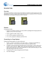
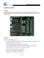
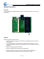
CY3655 Hardware User Guide
Introduction
CY3655 Hardware User Guide
This manual describes the hardware in the Cypress CY3655 Development Kit (DVK). The four
main boards included in the kit are the following:
•
enCoRe II Applications board
•
enCoRe II Pod
•
Wireless enCoRe II Pod
•
Modular Programmer Base
The next sections provide a description of the hardware circuitry on the boards.
Please refer as needed to the Appendix for a definition of abbreviations and terms used
throughout the manual.
Additional hardware documentation that should be used in conjunction with this document can
be found in the PSoC Designer™ Help/Documentation menu. You will find a subdirectory
called “CY3655 DVK\Hardware” that contains schematics, layout files, and Bill-of-Materials for
the Applications board in this kit.
Cypress Semiconductor Corporation • 3901 North First Street • San Jose • CA 95134 • 408-943-2600
CY3655 Hardware User Guide
Emulator Pods
Overview
The Cypress enCoRe II emulator pod and the Wireless enCoRe II emulator pod are part of the
debugging and emulation system used for development with the Cypress enCoRe II low-speed
USB controller and Cypress Wireless enCoRe II controller.
Features
Pod features Include:
•
Support for enCoRe II emulation for most enCoRe II packages with the appropriate foot
adapter and the ICE-Cube emulator.
•
Power supplied by either system or ICE.
•
4.0v to 5.25v operation for enCoRe II Pod.
•
2.7v to 3.6v operation for Wireless enCoRe II Pod.
Connecting to a Target System
Perform the following steps to use the emulator pod:
1.
Solder or connect a foot adapter to the target system. (A sample of each PDIP foot
ships with the kit. Surface mount feet can be ordered as separate items).
2.
Carefully connect the pod to the foot and ensure to orient the pin 1 corner of the pod to
the pin 1 corner of the foot. Note: There is an index pin position that is off the normal
grid of the pin-grid array on both the pod and the foot. Be sure that the index pin on the
pod aligns with the index pin on the foot.
3.
Connect the ICE to the pod using the blue RJ45 cable.
4.
Run PSoC Designer.
Page 2 of 16
CY3655 Hardware User Guide
Foot Part Numbers
The following table shows the Cypress foot part number that supports each enCoRe II device
footprint.
enCoRe II or
Wireless enCoRe II Part
Number
CY7C63923-PVXC
Emulation Foot
Ordering Number
CY3655-01
CY7C60123-PVXC
Emulation Foot
Visual Identification
Numbers
Yellow Lettering –
“P4549C”
Package
Description
SSOP-48 Surface Mount
Black Lettering –
“SSOP48”
CY7C63913-PXC
CY3655-02
CY7C60123-PXC
Yellow Lettering –
“P4548B”
PDIP-40 Through-hole
Black Lettering –
“PDIP40”
CY7C63903-PVXC
CY3655-03
CY7C60113-PVXC
CY7C63823-PXC
Yellow Lettering – none
SSOP-28 Surface Mount
Black Lettering –
“P4552A”
CY3655-04
CY7C60223-PXC
Yellow Lettering –
“P4546C”
PDIP-24 Through-hole
Black Lettering –
“PDIP24”
CY7C63823-SXC
CY3655-05
CY7C60223-SXC
Yellow Lettering –
“P4547B”
SOIC-24 Surface Mount
Black Lettering – “SO24”
CY7C63823-QXC
CY3655-06
CY7C60223-QXC
CY7C63813-PXC
Yellow Lettering – none
QSOP-24 Surface Mount
Black Lettering – “24”
CY3655-07
Yellow Lettering –
“P4544C”
PDIP-18 Through-hole
Black Lettering –
“PDIP18”
CY7C63813-SXC
CY3655-08
Yellow Lettering –
“P4545A”
SOIC-18 Surface Mount
Black Lettering – “SO18”
CY7C63801-PXC
CY3655-09
CY7C63310-PXC
Yellow Lettering –
“P4543C”
PDIP-16 Through-hole
Black Lettering –
“PDIP16”
CY7C63803-SXC
CY3655-10
CY7C63801-SXC
Yellow Lettering –
“P4550A”
CY7C63310-SXC
Black Lettering – “SO16”
Page 3 of 16
SOIC-16 Surface Mount
CY3655 Hardware User Guide
Power Supply to Pod
The pod can have power supplied either by the ICE or by your system. Configure the project
debugger settings in PSoC Designer with the appropriate power supply setting. See PSoC
Designer documentation for information on setting power options for the debugger.
Using the enCoRe II Internal 3.3 Volt Regulator Output (VREG)
Some enCoRe II devices have a built-in 3.3-volt regulator that can be used to supply external
devices with regulated voltage. To use the regulator for external devices, a 1.0uF or larger
ceramic cap must be loaded close to the output pin. When using the pod, this capacitor must
be loaded on position C12 on the bottom side of the pod board. The capacitor footprint on the
board at C12 is a 0805 sized surface mount footprint. Note that this capacitor must not be
loaded if using the VREG pin (P1.2) on enCoRe II as a GPIO. Be sure that the external
circuitry does not consume more power than the enCoRe II VREG output can provide as
specified in the data sheet. Note that the Wireless enCoRe II does not have an internal
voltage regulator.
External Clock Use with Pods
Emulation is not supported when using an external clock source for the enCoRe II’s CPU
clock. Designs which need external clock inputs are advised to use the internal clock for
emulation, then switch to the external clock for final testing.
Page 4 of 16
CY3655 Hardware User Guide
Applications Board
Overview
The Cypress enCoRe II DVK Applications board is a versatile development platform used to
develop with the Cypress enCoRe II low-speed USB peripheral controller or Wireless enCoRe
II Microcontroller.
Features
Application board features Include:
•
Supports either PDIP-24 or PDIP-40 enCoRe II devices or Wireless enCoRe II devices
•
Supports either USB or PS/2 connector
•
Supports alternate signal connections to PS/2 connector
•
5-pin programming header available for In-System-Serial-Programming support
•
High signal visibility with quick-connect logic analyzer support
•
Through-hole and surface mount prototype area
•
Buttons and LEDs available for development
•
Supports use of enCoRe II emulation system
Page 5 of 16
CY3655 Hardware User Guide
USB Port
The USB type-B connector allows a USB connection to a PC. The power pin of the connector
goes to a jumper (J5) labeled “VBUS PWR” to allow USB power to be disconnected from the
system for emulator based development. In addition the USB signals can be viewed with an
oscilloscope or logic analyzer at header J7. For best USB signal quality, remove the jumpers
on J8 and J9 that connect the PS/2 port.
PS/2 Port
The PS/2 connector allows a PS/2 connection to a PC using the supplied cable. The power
pin of the connector goes to a jumper (J13) labeled “PS/2 PWR” to allow PS/2 power to be
disconnected from the system for emulator based development. In addition the PS/2 signals
can be viewed with an oscilloscope or logic analyzer at header J7. The enCoRe II pins used
for PS/2 are normally P1.0 and P1.1, but the alternate pins P1.5 and P1.6 can be used by
moving the jumpers on J8 and J9 to the side labeled “ALT PS/2”.
Analyzer Headers
P1, P2, and P3 are 20-pin headers that are compatible with Agilent logic analyzer terminator
adapters. This feature allows for a quick and simple debugging connection.
Prototyping Area
An area on the board is available for user-customized prototyping. The through-hole area
contains 0.1” spaced holes appropriate for DIP devices. On each side of the through-hole area
there is a ground row and a power row. Each power row can be individually configured to use
either the board’s VCC or the VREG output from the enCoRe II. There is also a surface mount
prototype area that accepts either 0.050” pitch parts or 0.025” pitch parts. Holes on the
outside of the surface mount pads allow signals to easily be soldered from elsewhere on the
board. A single row of signals above the proto area allows enCoRe II signals to be wired to
the proto area. This row has all signal names in silkscreen by their respective holes on both
the top and bottom side of the board.
Page 6 of 16
CY3655 Hardware User Guide
Pushbuttons and LEDs
Three pushbuttons and three LEDs are available on the board for general purpose use. The
following table shows the enCoRe II signal name relation to the pushbutton or LED and its
jumper.
Pushbutton or LED
Jumper
enCoRe II Signal Name
D1 LED
J12
P0.5
D2 LED
J17
P0.6
D3 LED
J19
P1.3
S1 Pushbutton
J11
P0.2
S2 Pushbutton
J16
P0.3
S3 Pushbutton
J18
P0.4
The jumpers can be used to isolate the LED or pushbutton from the enCoRe II if desired. Note
that the LEDs use the same power as the enCoRe II. Driving the enCoRe pin low illuminates
the LEDs, and pushbutton presses can be detected by making the appropriate enCoRe II pin
an input with the pull-up enabled and detecting a low level when the button is pressed. Also
note that the pushbutton inputs are connected to enCoRe II pins that can be configured as
external interrupt pins.
Suggestions for Connecting the Pod
The Applications board can be used in conjunction with PSoC Designer and a pod for
development using the ICE-Cube in-circuit emulator. To do this, place either the PDIP-40 or
PDIP-24 foot into the socket at U1 and attach the pod. Note that the PDIP-18 and PDIP-16
feet cannot be used on the Applications board as their pin-outs differ substantially from the
PDIP-24 foot.
External Crystal or Ceramic Resonator Use
An external crystal or ceramic resonator can be used with the PDIP-40 part if a custom
frequency or tighter tolerance frequency is needed. The footprint at Y1 on the board can be
loaded with an HC49 sized through-hole or surface-mount crystal. Optionally a two- or
three-pin ceramic resonator can be used in this position. When using a crystal or ceramic
resonator, the resistors R2 and R3 should be removed to isolate the clock signals from the rest
of the board. Positions C4 and C5 should be populated with the appropriate load capacitance
for enCoRe II and the chosen crystal or ceramic resonator. Note that three-pin ceramic
resonators with built-in load capacitors do not need external capacitors loaded. Refer to the
enCoRe II data sheet for details on crystal or ceramic resonator specifications. Note that the
24-pin enCoRe II device does not support external crystals or ceramic resonators.
Page 7 of 16
CY3655 Hardware User Guide
Using the enCoRe II Internal 3.3 Volt Regulator Output (VREG)
The enCoRe II has a built-in 3.3-volt regulator that can be used to supply external devices with
regulated voltage. To use the regulator for external devices, a 1.0uF or larger ceramic cap
must be loaded close to the output pin. For 40-pin devices, load the capacitor on position C2.
For 24-pin devices load the capacitor on position C9. The capacitor footprints on the board at
C2 and C9 are 0805 sized surface mount footprints. In addition there is a larger footprint
available to add a tantalum or electrolytic capacitor at C1 if more capacitance is desired for
larger transients, although the ceramic capacitor must still be used at C2 or C9 even if C1 is
loaded. Note that these capacitors must not be loaded if using the VREG pin (P1.2) on
enCoRe II as a GPIO. Be sure that the external circuitry does not consume more power than
the enCoRe II VREG output can provide as specified in the data sheet. Note that some
enCoRe II devices and all Wireless enCoRe II devices do not have an internal 3.3v regulator.
Wireless enCoRe II Development using the Applications Board
The Applications board provides a useful platform for Wireless enCoRe II development. The
following is a list of items to keep in mind when using the Applications board for Wireless
enCoRe II development.
•
External power can be easily connected to the board using the Vcc and GND headers.
•
The Wireless enCoRe II Pod must be used for emulation with voltages below 4 volts.
•
The prototyping area of the board can be used to attach radio modules or other
components.
•
Be aware of voltage restraints when using in-circuit programming. The ICE-Cube
powers the target at 3.3 volts when programming. The MiniProg powers the target at 5
volts when programming. Make sure any extra circuitry on the target board can
withstand the programming voltage.
In-circuit Programming on the Applications Board
enCoRe II devices and Wireless enCoRe II devices can be programmed while on the
Applications board using the ICE-Cube. Follow the programming steps below:
1. Using a USB cable plug the ICE-Cube into a PC that has the PSoC Programmer
application installed. Make sure the ICE-Cube is powered on.
2. Connect the yellow ISSP cable to the ICE-Cube through the RJ45 adapter. Note: Do
not use a black ISSP cable as it does not properly support enCoRe II or Wireless
enCoRe II.
3. Place the 5-pin end of the ISSP cable on the 5-pin header (J2) of the Applications
board. It will only go on in one orientation.
4. Make sure no external power supply is connected to Vcc or GND on the Applications
board. Make sure that a USB cable is not connected to connector J6. Make sure that a
PS/2 cable is not connected to connector J10. Note that the programming is done over
Page 8 of 16
CY3655 Hardware User Guide
the P1.0 and P1.1 pins, so any extra circuitry connected to those pins could affect
programming success. Also note that the programming from ICE-Cube is done with
ICE-Cube supplying 3.3 volts to the target system, so make sure any connected devices
can tolerate that voltage. The ICE-Cube is limited to properly supplying a maximum of
250 mA to the target circuit during programming.
5. Launch the PSoC Programmer application.
6. In the programming application, select the Port as the ICE-Cube by choosing
“USB/xxxxCxxx” where the “x” is specific to the USB device ID of your ICE-Cube. Most
likely, the ICE-Cube will be the only device in the list that is not an LPT port.
7. First select the appropriate device family then select the device to be programmed.
8. Load the programming file using the “File Load” button.
9. Program.
enCoRe II devices and Wireless enCoRe II devices can be programmed while on the
Applications board using the MiniProg (sold separately). Follow the programming steps below:
1. Using a USB cable, plug the MiniProg programmer into a PC that has the PSoC
Programmer application installed.
2. Place the MiniProg programmer on the 5-pin header (J2) of the Applications board. It
will only attach in one orientation. Note that there may be slight mechanical interference
with the MiniProg from the J9 header, but it will still work properly.
3. Make sure no external power supply is connected to Vcc or GND on the Applications
board. Make sure there is not a USB cable connected to connector J6. Make sure
there is not a PS/2 cable connected to connector J10. Note that the programming is
done over the P1.0 and P1.1 pins, so any extra circuitry connected to those pins could
affect programming success. Also note that the programming from MiniProg is done
with MiniProg supplying 5 volts to the target system, so make sure any connected
devices can tolerate that voltage. The MiniProg is limited to properly supplying a
maximum of 100 mA to the target circuit during programming.
4. Launch the PSoC Programmer application.
5. In the programming application, select the Port as the MiniProg. After selecting the
MiniProg, make sure that in the “Results” column of the window, an unexpected
firmware version was not found. If necessary, update the MiniProg’s firmware by
choosing “Upgrade Firmware” in the “Utilities” menu.
6. First select the appropriate device family then select the device to be programmed.
7. Load the programming file using the “File Load” button.
8. Program.
Page 9 of 16
CY3655 Hardware User Guide
Modular Programmer
Overview
The Cypress Modular Programmer allows enCoRe II and Wireless enCoRe II devices to be
programmed.
Features
Modular Programmer features Include:
•
Complete programming support for all enCoRe II and Wireless enCoRe II devices in
PDIP packages
•
Programming support for all enCoRe II and Wireless enCoRe II devices in surface
mount packages with purchase of the appropriate surface-mount adapter socket (sold
separately)
•
Support for programming from ICE-Cube
•
Support for programming from MiniProg (sold separately)
•
Modular Programmer supports many other Cypress devices by obtaining the
appropriate inexpensive adapter card and socket adapter (if needed)
Page 10 of 16
CY3655 Hardware User Guide
Programming enCoRe II or Wireless enCoRe II on the Modular Programmer
enCoRe II devices and Wireless enCoRe II devices can be programmed on the Modular
Programmer using the ICE-Cube. Follow the programming steps below:
1. Using a USB cable, plug the ICE-Cube into a PC that has the PSoC Programmer
application installed. Make sure the ICE-Cube is powered on.
2. Connect the yellow ISSP cable to the ICE-Cube through the RJ45 adapter. Note: Do
not use a black ISSP cable as it does not properly support enCoRe II or Wireless
enCoRe II.
3. Place the 5-pin end of the ISSP cable on the 5-pin header (J2) of the Modular
Programmer Base. It will only go on in one orientation.
4. Place enCoRe II or Wireless enCoRe II device in the socket on the Modular
Programmer Base. Any PDIP package is supported natively. Surface mount devices
will require a surface-mount to PDIP adapter (sold separately). See the Programming
Support Matrix table in the next section for recommended surface-mount to PDIP
adapters.
5. Make sure the appropriate module supporting your specific enCoRe II or Wireless
enCoRe II device is in the memory-style DIMM slot of the Modular Programmer Base.
See the table below to find which module and which orientation of the module supports
your device. Note that the correct side of the module (A or B) must be connected to the
DIMM connector, and the module must be snapped properly in place.
6. Launch the PSoC Programmer application.
7. In the programming application, select the Port as the ICE-Cube by choosing
“USB/xxxxCxxx” where the “x” is specific to the USB device ID of your ICE-Cube. Most
likely, the ICE-Cube will be the only device in the list that is not an LPT port.
8. First select the appropriate device family then select the device to be programmed.
9. Load the programming file using the “File Load” button.
10. Program.
Alternatively, a MiniProg programmer (sold separately) can be used for programming rather
than the ICE-Cube. Follow the programming steps below:
1. Using a USB cable, plug the MiniProg programmer into a PC that has the PSoC
Programmer application installed.
2. Place the MiniProg programmer on the 5-pin header (J2) of the Modular Programmer
Base. It will only attach in one orientation.
3. Place enCoRe II or Wireless enCoRe II device in the socket on the Modular
Programmer Base. Any PDIP package is supported natively. Surface mount devices
will require a surface-mount to PDIP adapter (sold separately). See the Programming
Support Matrix table in the next section for recommended surface-mount to PDIP
adapters.
Page 11 of 16
CY3655 Hardware User Guide
4. Make sure the appropriate module supporting your specific enCoRe II or Wireless
enCoRe II device is in the memory-style DIMM slot of the Modular Programmer Base.
See the table below to find which module and which orientation of the module supports
your device. Note that the correct side of the module (A or B) must be connected to the
DIMM connector, and the module must be snapped properly in place.
5. Launch the PSoC Programmer application.
6. In the programming application, select the Port as the MiniProg. After selecting the
MiniProg, make sure in the “Results” column of the window that an unexpected firmware
version was not found. If necessary, update the MiniProg’s firmware by choosing
“Upgrade Firmware” in the “Utilities” menu.
7. First select the appropriate device family then select the device to be programmed.
8. Load the programming file using the “File Load” button.
9. Program.
Page 12 of 16
CY3655 Hardware User Guide
Programming Support Matrix
The table below shows the pieces necessary to program each device on the Modular
Programmer. The table is applicable whether programming from the ICE-Cube or the
MiniProg.
enCoRe II or
Wireless enCoRe
II Part Number
Package
Description
CY7C63923-PVXC
SSOP-48 Surface Mount
CY7C60123-PVXC
Suggested Surface-Mount to
DIP Adapter
Emulation Technology
AS-48-48-01SS-6-GANG
Programming
Module
CY3216-01 Side A
Logical Systems PA48QS-1387-6
CY7C63913-PXC
PDIP-40 Through-hole
NA
CY3216-01 Side A
SSOP-28 Surface Mount
Emulation Technology
AS-28-28-02SS-6ENP-GANG
CY3216-01 Side A
CY7C60123-PXC
CY7C63903-PVXC
CY7C60113-PVXC
Logical Systems PA28SS-OT-3
CY7C63823-PXC
PDIP-24 Through-hole
NA
CY3216-02 Side B
SOIC-24 Surface Mount
Emulation Technology
AS-24-24-02S-3-GANG
CY3216-01 Side A
CY7C60223-PXC
CY7C63823-SXC
CY7C60223-SXC
Logical Systems PA24SO1-08H-3
CY7C63823-QXC
QSOP-24 Surface Mount
Logical Systems 24QS-OT
CY3216-02 Side A
CY7C63813-PXC
PDIP-18 Through-hole
NA
CY3216-01 Side B
CY7C63813-SXC
SOIC-18 Surface Mount
Emulation Technology
AS-18-18-01S-3-GANG
CY3216-01 Side A
CY7C63801-PXC
PDIP-16 Through-hole
NA
CY3216-03 Side A
SOIC-16 Surface Mount
Emulation Technology
AS-16-16-04S-3-MS-CY3079
CY3216-01 Side A
CY7C60223-QXC
CY7C63310-PXC
CY7C63803-SXC
CY7C63801-SXC
CY7C63310-SXC
Logical Systems PA16SO1-03-3
Page 13 of 16
CY3655 Hardware User Guide
Other Kit Hardware
Overview
This section describes the rest of the hardware components that are part of the Cypress
enCoRe II DVK.
5-Pin to USB Adapter
The 5-Pin to USB adapter is a small board that allows enCoRe II based devices to be
programmed through their USB cables using the MiniProg (sold separately). This adapter is
not designed to be used with the ICE-Cube and ISSP cable due to cable length restrictions
during programming. The steps below describe the programming procedure using the
MiniProg.
1. Using a USB cable, plug the MiniProg programmer into a PC that has the PSoC
Programmer application installed.
2. Connect the 5-pin to USB adapter to the MiniProg programmer. It will only attach in one
orientation.
3. Connect the USB end of the 5-pin to USB adapter to the USB cable of a device that
uses enCoRe II. Note that the USB device must have a cable no longer than 1 meter.
Typical target devices are mice and keyboards.
4. Launch the PSoC Programmer application.
5. In the programming application, select the Port as the MiniProg. After selecting the
MiniProg, make sure that in the “Results” column of the window that an unexpected
firmware version was not found. If necessary, update the MiniProg’s firmware by
choosing “Upgrade Firmware” in the “Utilities” menu.
6. First select the appropriate device family then select the device to be programmed.
7. Load the programming file using the “File Load” button.
8. Program.
Page 14 of 16
CY3655 Hardware User Guide
Appendix A — Definitions
5-Pin to USB Adapter
The small adapter board in this kit that allows enCoRe II based devices to be
programmed through their USB cables using a MiniProg.
Applications Board
The board in this kit that can be used to develop applications for the enCoRe II low
speed USB peripheral controller or Wireless enCoRe II Microcontroller.
DVK
Development Kit
enCoRe II
The Cypress low speed USB peripheral controller supported by this kit. The enCoRe II
family also includes the Wireless enCoRe II, which is supported by this kit.
Foot
Any of several small adapter boards used to connect the emulation pod to the footprint
of enCoRe II or Wireless enCoRe II for emulation.
ICE
See In-Circuit Emulator
In-Circuit Emulator
A device used to allow debugging of an enCoRe II or Wireless enCoRe II project. This
kit uses the ICE-Cube in-circuit emulator.
ISSP Cable
The In-System-Serial-Programming cable that can be connected between the ICE and
either the applications board or Modular Programmer for enCoRe II or Wireless
enCoRe II device programming.
MiniProg
A USB based programmer that can be used to program enCoRe II or Wireless enCoRe
II devices.
Modular Programmer
A board that can be used to program enCoRe II and Wireless enCoRe II silicon of
various package types using a modular system of socket adapters and programming
modules in conjunction with either the ICE-Cube or the MiniProg.
Pod
A small board used in conjunction with PSoC designer, an ICE-Cube, and a foot for
debugging and emulation.
Programming Module
Used with the Modular Programmer to support different enCoRe II and Wireless
enCoRe II pinouts for programming.
Programming socket
adapter
Used with the Modular Programmer to support different enCoRe II and Wireless
enCoRe II packages for programming.
PS/2
A device interface developed by IBM that is used for many modern keyboards and
mice.
PSoC Designer
A software development environment used for enCoRe II and Wireless enCoRe II
firmware development
PSoC USB-4000
A USB to parallel adapter used to make a USB connection between the development
PC running PSoC Designer and the ICE-4000. This kit does not support use of either
the PSoC-4000 or ICE-4000.
RDK
Reference Design Kit
RJ45 Cable
A short blue cable used for connection between the ICE and pod.
USB
Universal Serial Bus
VREG
The internal 3.3 volt regulator in some enCoRe II devices that can also provide current
to external devices.
Wireless enCoRe II
The Cypress low-voltage microcontroller supported by this kit. Wireless enCoRe II is a
member of the Cypress enCoRe II family.
Page 15 of 16
CY3655 Hardware User Guide
Document Revision History
Revision #
Date
Comments
Alpha
Release
12/14/2004
Initial Release Accompanying Kit Revision 1.0
Beta
Release
4/04/05
Beta kit updates
Page 16 of 16