1
CITIZEN
User's Manual
Model : iDP-3420/3421/3423
Dot Matrix Printer
Rev 1.00 Newly Issued on 20.Oct.1998
Japan CBM Cor poration
Infor mation Systems Div.
iDP-3420/3421/3423 User’s Manual
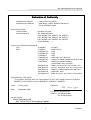
Declaration of Confor mity
Manufacturer’s Name :
Manufacturer’s Address
Declare the Product
Product Name
Model Number(s)
: Japan CBM Corporation
: CBM Bldg., 5-68-10, Nakano, Nakano-ku
Tokyo, 164-0001, Japan
Dot Matrix Printer
iDP-3420/3421/3423
(iDP-3420R/P, iDP-3420S/C, iDP-3420T/I)
(iDP-3421R/P, iDP-3421S/C, iDP-3421T/I)
(iDP-3423R/P, iDP-3423R/P, iDP-3423T/I)
(S.NO.98X0001 - )
Conform to the following Standards
LVD
: EN60950
EMC
: EN55022
: EN61000-3-2
: EN61000-3-3
: EN50082-1
: EN61000-4-2
: EN61000-4-3
: ENV50204
: A4:1997
: 1994 Class B
: 1995
: 1995
: 1997
: 1995 ±4KV CD, ±8KV AD
: 1995 3V/m, 80MHz-1000MHz AM 1KHz 80%
: 1995 3V/m, 895MHz-905MHz
(Pulse 200Hz, duty cycle 50%)
: EN61000-4-4
: EN61000-4-5
: EN61000-4-6
: EN61000-4-8
: EN61000-4-11
: 1995±1.0KV(AC Mains),±0.5KV(Signal Lines)
: 1995 1KV Differential mode, 2KV Common mode
: 1996 3V, 0.15MHz-80MHz AM 1KHz 80%
: 1993 50Hz, 3A/m
: 1994 -30%, 10ms / -60%, 100ms / -100%,5000ms
Supplementary Information
“The product complies with the requirements of the Low Voltage Directive 73/23/EEC,
93/68/EEC and the EMC Directive 89/336EEC, 92/31/EEC, 93/68EEC”
Place
Tokyo, Japan
Date
September.1998
Signature
Full Name : Mikio Moriya
Position : General Manager
R & D Department
Europe Contact :
Norco Declaration AB
Box 7146 S-250 07 Helsingborg Sweden
This declaration is applied only for 230V model.
2
CITIZEN
iDP-3420/3421/3423 User’s Manual
IMPORTANT SAFETY INSTRUCTIONS
·Read all of these instructions and save them for future reference.
·Follow all warnings and instructions marked on the product.
·Unplug this product from the wall outlet before cleaning. Do not use liquid or aerosol
cleaners. Use a damp cloth for cleaning.
·Do not use this product near water.
·Do not place this product on an unstable cart, stand or table. The product may fall, causing
serious damage to the product.
·Slots and openings on the back or bottom of the case are provided for ventilation. To ensure
reliable operation of the product and to protect it from overheating, do not block or cover
these openings. The openings should never be blocked by placing the product on a bed,
sofa, rug of other similar surface. This product should never be placed near or over a
radiator or heater. This product should not be placed in an built-in installation unless
proper ventilation is provided.
·This product should be operated from the type of power source indicated on the marking
label. If you re not sure of the type of power available, consult your dealer or local power
company.
·Do not allow anything to rest on the power cord. Do not place this product where the cord
will be walked on.
·If an extension cord is used with this product, make sure that the total of the ampere ratings
of the products plugged into the extension cord does not exceed the extension cord ampere
rating. Also, make sure that the total of all products plugged into the wall outlet does not
exceed 15 amperes.
·Never push objects of any kind into this product through cabinet slots as they may touch
dangerous voltage points or short out parts that could result in a risk of fire or electric
shock. Never spill liquid of any kind on the product.
·Except as explained elsewhere in this manual, do not attempt to service this product by
yourself. Opening and removing the covers that are marked “Do Not Remove” may expose
you to dangerous voltage points or other risks. Refer all servicing on those compartments
to service personnel.
·Unplug this product from the wall outlet and refer servicing to qualified service personnel
under the following conditions:
A. When the power cord or plug is damaged or frayed.
B. If liquid has been spilled into the product.
C. If the product has been exposed to rain or water.
D. If the product does not operate normally when the operating instructions are followed.
Adjust only those controls that are covered be the operating instructions since improper
adjustment of other controls may result in damage and will often require extensive
work by a qualified technician to restore the product to normal operation.
E. If the product has been dropped or the cabinet has been damaged.
F. If the product exhibits a distinct change in performance, indicating a need for service.
·Please keep the poly bag which this equipment is packed in away from children or throw it
away to prevent children from putting it on. Putting it on may cause suffocation.
3
CITIZEN
iDP-3420/3421/3423 User’s Manual
WICHTIGE SICHERHEITSANWEISUNG
UNGEN
·Lesen Sie die nachfolgenden Anweisungen sorgfältig durch und bewahren Sie sie auf.
·Befolgen Sie alle auf dem Drucker vermerkten Hinweise und Anweisungen. Vor dem
Reinigen grundsätzlich Stecker aus der Steckdose ziehen. Keine Flüssigkeiten oder
Aerosolreiniger benutzen. Nut mit einem feuchten Tuch abwischen.
·Der Drucker darf nicht in der Nähe von Wasser aufgestellt werden.
·Drucker nicht auf einem unstabilen Wagen, Stand oder Tisch aufstellen. Der Drucker
könnte herunterfallen und dabel beschädigt werden.
·Schlitze und Öffnungen im Gehäuse, in der Rückwand und im Boden dienen der Belüftung.
Sie dürfen keinesfalls zugedeckt oder blockiert werden, da sich der Drucker sonst
überhitzt. Drucker nicht auf ein Bett, Sofa, Teppich oder dergleichen stellen. Drucker
nicht in der Nähe eines Heizkörpers aufstellen. Drucker darf nicht eingebaut werden,
falls nicht für ausreichende Belüftung gesorgt ist.
·Drucker nur mit der auf dem Typschild angegebenen Spannung betreiben. Wenn Sie sich
nicht sicher sind, fragen Sie ihren Händler oder ihr zuständiges Elektrizitätswerk.
·Nichts auf das Stromanschlußkabel stellen. Kabel muß so verlegt werden, daß man nicht
darauftreten kann.
·Ein etwaiges Verlängerungskabel muß der Stromstärke aller daran angeschlossenen Geräte
entsprechen.
·Keine Gegenstände in die Gehäuseschlitze schieben.
·Drucker darf nur da gewartet werden, wo im Handbuch angegeben, Öffnen und.
Abnehmen von Abdeckungen, die mit “Do not remove” gekennzeichenet sind, könnte
gefährliche spannungführende Stellen oder sonstige Gefahrenpunkte freilegen. Die
Wartung solcher Stellen darf grundsätzlich nur von besonders ausgebildetem
Fachpersonal vorgenommen werden.
A. Wenn das Stromanschlußkabel oder der Stecker beschädigt oder durch-gescheuert ist.
B. Wenn Flüssigkeit auf dem Drucker verschüttet wurde.
C. Wenn der Drucker im Regen gestanden hat oder Wasser darauf verschüttet wurde.
D. Wenn der Drucker trotz genauer Befolgung der Betriebsvorschriften nicht richtig
arbeitet. Nur die in der Bedienungsanleitung angegebenen Einstellungen vornehmen.
Ein Verstellen anderer Bedienungselemente könnte den Drucker beschädigen und
macht umständliche Arbeiten eines qualifizierten Technikers erforderlich, um den
Drucker Wieder auf den normalen Betrieb einzustellen.
E. Wenn der Drucker heruntergefallen ist oder das Gehäuse beschädigt wurde.
F. Wenn der Drucker in seiner Leistung nachläßt.
·Bitte halten Sie den Kunststoffbeutel, in den die Ware verpackt ist, von Kindern entfernt,
oder werfen Sie ihn weg, damit er nicht in die Hande von Kindern gerät. Das Überstülpen
des Beutels kann zum Ersticken führen.
Lärmemission kleiner 70dBA
4
CITIZEN
iDP-3420/3421/3423 User’s Manual
IMPORTANT:: This equipment generates, uses, and can radiate radio frequency energy and
if not installed and used in accordance with the instruction manual, may cause interference
to radio communications.
It has been tested and found to comply with the limits for a Class
A computing device pursuant to Subpart J of Part 15 off FCC Rules, which are designed to
provide reasonable protection against such interference when operated in a commercial
environment.
Operation of this equipment in a residential area is likely to cause
interference, in which case the user at his own expense will be required to take whatever
measures may be necessary to correct the interference.
CAUTION: Use shielded cable for this equipment.
Sicherheitshinweis
Die Steckdose zum Anschluß dieses Druckers muß nahe dem Grät angebracht und leicht
zugänglich sein.
For Uses in Canada
This digital apparatus does not exceed the class A limits for radio noise emissions from digital,
apparatus, as set out in the radio interference regulations of the Canadian department of
communications.
Pour L’utilisateurs Canadiens
Cet appareil numérique ne dépasse pas les limites de carégorie a pour les émissions de bruit
radio émanant d’appareils numériques, tel que prévu dans les réglements sur l’interférence
radio du départment Canadien des communications.
5
CITIZEN
iDP-3420/3421/3423 User’s Manual
<CAUTIONS>
1. Prior to using the equipment, be sure to read this User's Manual thoroughly. Please keep it handy
for reference whenever it may be needed.
2. The information contained herein may be changed without prior notice.
3. Reproduction of part or all of this User's Manual without permission is strictly prohibited.
4. Never service, disassemble, or repair parts that are not mentioned in this User's Manual.
5. Note that we will not be responsible for damages attributable to a user's incorrect operation/
handling or an improper operating environment.
6. Operate the equipment only as described in this User's Manual; otherwise accidents or problems
may result.
7. Data are basically temporary; they cannot be stored or saved permanently or for a long time.
Please note that we will not be responsible for damages or losses of profit resulting from losses of
the data attributable to accidents, repairs, tests, and so on.
8. If you have any questions or notice any clerical errors or omissions regarding the information in
this manual, please contact our office.
9. Please note that, notwithstanding Item 8 above, we will not be responsible for any effects resulting
from operation of the equipment.
6
CITIZEN
iDP-3420/3421/3423 User’s Manual
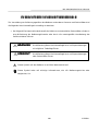
SAFETY PRECAUTIONS --------- BE SURE TO OBSERVE
In order to prevent hazards to an operator or other persons and damage to property, be sure to observe
the following precautions.
· The following describes the degrees of hazard and damages that can occur if the given
instructions are neglected or the equipment is incorrectly operated.
WARNING
Negligence of this precaution may result in death or serious
injury.
CAUTION
Negligence of this precaution may result in injury or damage to
property.
This is an illustration mark used to alert your attention.
This is an illustration mark used to indicate such information as an instruction or the like.
7
CITIZEN
iDP-3420/3421/3423 User’s Manual
WARNING
· Never handle the equipment in the following manners, as it may break, become out of
order, or overheat causing smoke and resulting in fire or electric shock.
If the equipment is used in an abnormal condition, such as when broken, then problems,
smoke emission, abnormal odor/noise, and fire can result. If an abnormal condition exists,
be sure to turn off the power, disconnect the power plug from a plug socket, and contact our
dealer. Never repair the equipment on your own - it is very dangerous.
· Do not allow the equipment to receive a strong impact or shock, such as kicking, stomping,
hitting, dropping, and the like.
· Install the equipment in a well-ventilated place. Do not use it in such a manner that its
ventilation port will be blocked.
· Do not install the equipment in a place like a laboratory where chemical reactions are
expected, or in a place where salt or gases are contained in the air.
· Do not connect/disconnect a power cord or a data cable, while holding the cable. Do not
pull, install, use, or carry the equipment in such a manner that force will be applied to the
cables.
· Do not drop or insert any foreign substances, such as clips or pins, into the equipment.
· Do not spill any liquid or spray any chemical-containing liquid over the equipment. If any
liquid is spilled on it, turn off the power, disconnect the power cable and power cord from
the plug socket, and so on, and contact our dealer.
· Do not disassemble or remodel the equipment. Negligence of this may cause fire or
electric shock.
· Should you drop or break this AC adapter by any chance, unplug it immediately and
contact our office. Using it in that condition may result in fire or electric shock.
· Should water enter inside the equipment by any chance, unplug it and contact our office.
Using it in that condition may result in fire or electric shock.
· Use the equipment only with the specified commercial power supply. Negligence of this
may result in fire, electric shock, or problems.
· Do not damage, break, process, bend/pull by force, twist, or bundle an AC adapter cord.
Also, do not put a heavy substance on it or heat it. The AC adapter could be broken,
resulting in fire, electric shock, or trouble. If the AC adapter cord is damaged, contact our
office.
· Do not connect/disconnect the AC adapter with wet hands. It may result in electric shock
or other problems.
· Do not overload a single electrical outlet, using a table tap or a current tap socket. It may
result in fire or electric shock.
· An equipment packing bag must be discarded or kept away from children. A child can
suffocate if the bag is placed over the head.
8
CITIZEN
iDP-3420/3421/3423 User’s Manual
PREC
RECAUTIONS FOR INSTALLA
LLATION
· Do not use or store the equipment in a place exposed to fire, moisture, or direct sunlight, or
in a place near a heater or a thermal device where the prescribed operating temperature
and humidity are not met, or in a place exposed to much oil, iron powder, or dust. The
equipment may become out of order, emit smoke, or catch fire.
· Do not install the equipment in a place like a laboratory where chemical reactions are
expected, or in a place where salt or gases are contained in the air. There is a danger of
fire or electric shock.
· Do not put any object on the printer. It may cause trouble.
· Do not use the equipment near a radio or TV receiver. Do not share the power from a plug
socket a radio or TV receiver is connected to. It may cause a reception problem.
· Use the equipment only at the specified voltage and frequency. Otherwise, it may emit
smoke and catch fire or cause other problems.
· Confirm that a plug socket used for connection has sufficient capacity.
· Do not overload a single electrical outlet in connecting the power cable. It may result in
the cable catching fire or a power outage. Also, do not stamp or put any object on the
cable.
· Never connect a grounding cable to a gas pipe. There is a danger of explosion. When
connecting or disconnecting the grounding cable, be sure to disconnect the power plug from
the plug socket.
· When connecting/disconnecting the cables, be sure to turn off the power first, including the
connected side, and then connect/disconnect them, holding a plug and a connector. Do not
pull or carry the equipment with a load applied to the cable.
· Connect a connector cable securely. If a reverse-polarity connection is made, internal
elements may be broken or a mating device may be adversely affected.
· Use a shielding wire or twisted pair wire for a signal line, in order to minimize noise effect.
Avoid connecting to a device that is likely to generate noise.
· When a drawer kick connector is provided, do not connect any device other than the
prescribed solenoid specifications. Negligence of this could cause trouble.
· Use the equipment in an environment where there is a plug socket near the main body and
you can easily disconnect the power plug from it, to shut off the power.
· When the equipment will not be used for a long period of time, unplug it.
· When transporting the equipment, remove the rolled paper from it.
· Install the equipment on a flat, stable desk in a well-ventilated place free from vibrations.
(Do not block the ventilation port.)
9
CITIZEN
iDP-3420/3421/3423 User’s Manual
PREC
RECAUTIONS FOR HANDLING
Do not handle the equipment in the following manners, because problems may result.
· Do not use a power supply other than the specified AC adapter.
· Do not print when there is no recording paper or ink ribbon set in the equipment.
The
print head may be damaged
· Be careful not to drop foreign substances, such as clips, pins, and screws, into the main
body.
· Do not spill any liquid or spray any chemical-containing liquid over the equipment.
· Do not stamp on, drop, hit, or give a strong shock to the equipment.
· Never use a pointed object, such as a pen, to operate the operation panel.
· Do not use Scotch tape to fasten paper together for continuous use.
· Never pull the set paper forcibly. When opening/closing the printer cover, take care that
the paper will not be caught.
To Prevent Injury and Spreading of Damage
· Do not touch the printing part of the print head.
· When turning on the power, do not touch the moving parts, such as a cutter and gear inside
the main body, or electric parts.
· Be careful to avoid bodily injure or damaging other objects with an edge of sheet metal.
· Should any error occur while operating the equipment, stop it immediately and disconnect
the power plug from the plug socket.
· Should a problem occur, leave solving it to our serviceman.
Do not disassemble the
equipment on your own.
· When opening/closing the cover, and so on, be careful not to catch your hand or finger on
the equipment.
10
CITIZEN
iDP-3420/3421/3423 User’s Manual
DAILY MAINTENANCE
· Prior to starting maintenance work, be sure to turn off the main body.
· Use a dry soft cloth to wipe off stains and dust from the surfaces of the main body case.
For severe soiling, dip the cloth in water and wring it, for wiping off the soil.
Never use
organic solvents, such as alcohol, thinner, trichlene, benzene, ketone, or chemical dusters.
· If the equipment is contaminated with paper powder, use a soft brush to clean it.
11
CITIZEN
iDP-3420/3421/3423 User’s Manual
CONTENTS
1. OUTLINE ..............................................................................................................................................15
1.1
Features ..............................................................................................................................................15
1.2
Unpacking...........................................................................................................................................15
2. BASIC SPECIFICATIONS ...................................................................................................................16
2.1
Model Classifications .........................................................................................................................16
2.2
Basic Specifications............................................................................................................................17
2.3
Paper Specifications ...........................................................................................................................18
2.3.1
Recommended Paper................................................................................................................ 18
2.3.2
Printing Position ...................................................................................................................... 18
2.3.3
Cutter Layout ........................................................................................................................... 18
3. OUTER APPEARANCE AND COMPONENT PARTS .......................................................................19
3.1
iDP-3420 .............................................................................................................................................19
3.2
iDP-3421 .............................................................................................................................................20
3.3
iDP-3423 .............................................................................................................................................21
4. OPERATION .........................................................................................................................................22
4.1
Connecting the Power Cord ...............................................................................................................22
4.2
Connecting Interface Cable ...............................................................................................................23
4.3
Attaching the Ferrite Core to the Interface Cable ........................................................................... 24
4.4
Connecting Drawer Kick-Out Connector ..........................................................................................25
4.5
Opening/Closing the Auto Cutter (iDP-3421/3423)..........................................................................25
4.6
Setting the Cassette Ribbon ..............................................................................................................26
4.7
Inserting the Paper ............................................................................................................................27
4.7.1
Inserting the Paper (iDP-3420/3421)...................................................................................... 27
4.7.2
Inserting the Paper Roll (Duplicable 2-sheet Paper)(iDP-3423)........................................... 29
4.7.3
Removing the Wound Paper Roll(iDP-3423) .......................................................................... 30
4.8
Adjusting the Paper Near End Sensor..............................................................................................30
4.9
How to Remove Remaining Paper Roll .............................................................................................31
4.10 Removing Paper Jam .........................................................................................................................31
4.11 Unlocking the Cutter(iDP-3421/3423) ..............................................................................................32
4.12 Operation Panel and Display of Error..............................................................................................33
4.13 Operation Flow at Power-on ..............................................................................................................34
12
CITIZEN
iDP-3420/3421/3423 User’s Manual
5. DIP SWITCH SETTING .......................................................................................................................35
5.1
Location of DIP Switch ......................................................................................................................35
5.2
DIP Switches Setting .........................................................................................................................36
6. PRESET JUMPER SETTING..............................................................................................................38
6.1
Location of Preset Jumper ................................................................................................................38
6.2
Preset Jumper Table ..........................................................................................................................38
7. MODE SETTING METHOD ................................................................................................................39
8. INPUT BUFFER BACKUP FUNCTION.............................................................................................40
8.1
Buffer Size ..........................................................................................................................................40
8.2
Input Buffer Backup ..........................................................................................................................40
8.3
Clearing the Input Buffer ..................................................................................................................40
9. PARALLEL INTERFACE .....................................................................................................................41
9.1
Specifications......................................................................................................................................41
9.2
Connector's Pin Configuration ..........................................................................................................41
9.3
Input and Output Signals..................................................................................................................42
9.3.1
Input and Output Signals ....................................................................................................... 42
9.3.2
Electrical Characteristics ........................................................................................................ 43
9.3.3
Timing Chart............................................................................................................................ 44
9.3.4
Data Receiving Control............................................................................................................ 44
10. SERIAL INTERFACE..........................................................................................................................45
10.1 Specifications......................................................................................................................................45
10.2 Connector's Pin Configuration ..........................................................................................................46
10.3 Input and Output Signals..................................................................................................................47
10.3.1 Input and Output Signals ....................................................................................................... 47
10.3.2 Data Configuration .................................................................................................................. 49
10.3.3 Error Detection ........................................................................................................................ 50
10.3.4 Data Receiving Control............................................................................................................ 50
10.3.5 Buffering................................................................................................................................... 50
10.3.6 Electrical Characteristics ........................................................................................................ 51
13
CITIZEN
iDP-3420/3421/3423 User’s Manual
11. DRAWER KICK-OUT CONNECTOR ................................................................................................52
11.1 Specifications of Drawer Kick-Out Connector .................................................................................52
11.2 Connector's Pin Configuration ..........................................................................................................52
11.3 Drive Circuit .......................................................................................................................................52
12. MAINTENANCE AND SERVICE ......................................................................................................53
13 PRINT CONTROL FUNCTIONS .......................................................................................................54
13.1 CBM Mode ..........................................................................................................................................54
13.1.1 Command List .......................................................................................................................... 54
13.1.2 Description of Items ............................................................................................................... 55
13.2 STAR Mode .........................................................................................................................................73
13.2.1 Command List .......................................................................................................................... 73
13.3 ESC/POS Mode.................................................................................................................................104
13.3.1 Command List ........................................................................................................................ 104
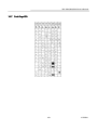
14. CHARACTER CODES TABLE .........................................................................................................126
14.1 CBM (Domestic) ...............................................................................................................................126
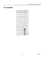
14.2 CBM (International) ........................................................................................................................127
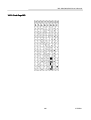
14.3 STAR (Domestic) ..............................................................................................................................128
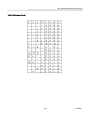
14.4 STAR (International) .......................................................................................................................129
14.5 Code Page 437 ..................................................................................................................................130
14.6 Katakana ..........................................................................................................................................131
14.7 Code Page 850 ..................................................................................................................................132
14.8 Code Page 860 ..................................................................................................................................133
14.9 Code Page 863 ..................................................................................................................................134
14.10 Code Page 865 ..................................................................................................................................135
14.11 Code Page 852 ..................................................................................................................................136
14.12 Code Page 866 ..................................................................................................................................137
14.13 Code Page 857 ..................................................................................................................................138
14.14 Windows Code...................................................................................................................................139
14.15 International Character Codes Table .............................................................................................140
APPENDIX 1. BLOCK DIAGRAM .......................................................................................................141
APPENDIX 2. OUTLINE DRAWING for iDP-3420 ............................................................................142
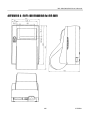
APPENDIX 3. OUTLINE DRAWING for iDP-3421 ............................................................................143
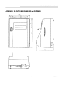
APPENDIX 4. OUTLINE DRAWING for iDP-3423 ............................................................................144
14
CITIZEN
iDP-3420/3421/3423 User’s Manual
<<< Ger man >>>
>>>
4. BETRIEB .............................................................................................................................................152
4.1
Anschluß des Netzkabels .................................................................................................................152
4.2
Anschluß des Schnittstellenkabels .................................................................................................153
4.3
Anbringen des Ferritkerns am Schnittstellenkabel ......................................................................154
4.4
Anschluß des Schubladenausschubsteckers ...................................................................................155
4.5
Öffnen/Schließen des automatischen Schneidemechanismus .......................................................155
4.6
Einlegen der Farbbandkassette ......................................................................................................156
4.7
Einlegen des Papiers........................................................................................................................157
4.7.1
Das Papier (iDP-3420/3421) einlegen. .................................................................................. 157
4.7.2
Einlegen der Papierrolle (doppellagiges Durchschlagpapier) (iDP-3423).......................... 159
4.7.3
Herausnehmen der vollen Papierrolle (iDP-3423)............................................................... 160
4.8
Ausrichten des Papierrestsensors ...................................................................................................160
4.9
Herausnehmen der Restpapierrolle ................................................................................................161
4.10 Beseitigung von Papierstaus ...........................................................................................................161
4.11 Initialisierung des Schneidemechanismus(iDP-3421/3423) ..........................................................162
4.12 Bedienfeld und Fehleranzeigen.......................................................................................................163
4.13 Betriebsfluß beim Einschalten ........................................................................................................165
5. DIP SCHALTER-EINSTELLUNG.....................................................................................................166
5.1
Lage der DIP-Schalter .....................................................................................................................166
5.2
DIP-Schalter-Einstellungen ............................................................................................................167
6. EINSTELLUNG DER VORWAHL-JUMPERSTECKER .................................................................169
6.1
Lage der Vorwahl-Jumperstecker ...................................................................................................169
6.2
Vorwahl-Jumperstecker-Tabelle......................................................................................................169
7. METHODE FÜR MODUSEINSTELLUNG......................................................................................170
12. WARTUNG UND DIENST ................................................................................................................171
Note:
Citizen, Citizen logo are registered trademark of Citizen Watch Co., Ltd.
ESC/POS and EPSON are a trademark and registered trademark of SEIKO EPSON Corporation.
STAR is a registered trademark of Star Micronics Corporation.
Windows is a registered trademark of Microsoft Corporation.
15
CITIZEN
iDP-3420/3421/3423 User’s Manual
1.
OUTLI
TLINE
This is a small-size dot impact printer developed for various data communication terminals,
POS terminals, kitchen-use printers, bank card, terminals, and so on.
Its abundant built-in features allow you to widely use this printer for different applications.
Prior to using it, read and understand this manual thoroughly.
1 .1
Features
(1) Small size, light weight, and low price
(2) High-speed print (Bi-directional)
(3) Red and black print
(4) Very easy paper loading by the auto loading function
(5) Paper end detecting function
(6) Built-in auto cutter (ACS-230) (iDP-3421)
(7) Built-in auto cutter and winder (iDP-3423)
(8) Built-in power supply
1 .2
Unpacking
(1) When unpacking the printer, confirm that the following parts are provided.
·Printer body
-----1 unit
·Cassette ribbon
-----1 piece
·Sample paper roll
-----1 roll
·User's manual
-----1 copy
·Power cord
---- 1 piece
·Ferrite core
---- 1 piece
·Fastener
---- 1 piece
CAUTION : · Install the printer on a flat and stable desk.
· Do not install the printer near a heater or in a place exposed to direct sunlight.
· Do not use the printer in a high-temperature, high-humidity, and
contaminated environment.
· Do not allow dew condensation on the printer.
If dew is condensed on it,
leave the power turned off until dew condensation is gone.
16
CITIZEN
iDP-3420/3421/3423 User’s Manual
2.
2 .1
BAS
BASIC SPECI
ECIFICATIONS
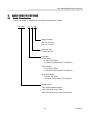
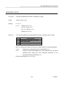
Model Classi
ssifications
The printer model is classified by the following designation method.
iDP 3420
- R F 120
Supply Voltage
120: For 120 V AC
230: For 230 V AC
Character Set
F: International
Interface
·CBM Mode
R: Serial (RS-232C)
P: Parallel (CENTRONICS Compliant)
·STAR Mode
S: Serial (RS-232C)
C: Parallel (CENTRONICS Compliant)
·ESC/POS Mode
T: Serial (RS-232C)
I: Parallel (CENTRONICS Compliant)
Model Name
·iDP-3420 Standard Model
·iDP-3421 With Auto Cutter
·iDP-3423 With Auto Cutter and Winder
17
CITIZEN
iDP-3420/3421/3423 User’s Manual
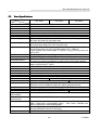
2 .2
Basic Specifications
Model
Item
Printer mechanism
Print method
Print width
Print head
Print speed
Print columns
Character size
Character types
iDP-3420
iDP-3421
iDP-3423
DP-410 series (CITIZEN)
Serial dot impact method (Bidirectional print)
64 mm
9 pins
Approx. 3 lines/second (At single-color continuous print)
40 or 42 columns (Selectable with the DIP switch)
1.31 mm(W) ´ 3.1 mm(H)
Alphanumeric, Katakana, International characters, Code page 850, 860,
863, 865, 852, 866, 857, Windows code
Line spacing
4.23 mm(1/6 inch) or 2.82(1/9 inch)
Minimum paper feed pitch: 1.41 mm(1/18 inch)
Paper
Ordinary paper and non-carbon paper: 76 +/- 0.5 mm(W) ´ f83 mm(OD);
Single-sheet paper: 45 to 55 kg/1,000 sheets/1,091 ´ 788 mm;
Copying paper: Non-carbon paper, 1 original + 1 copy, Total thickness 0.2
mm or less
Ink ribbon
Special purpose ribbon cartridge red/black or single color(Black)
Interface
Serial(RS-232C), Parallel(CENTRONICS compliant)
CBM mode, STAR mode, ESC/POS mode
Command system
The user can select the mode with the DIP switch and preset jumpers.
Print function
Provided by operating the on-line, self-test, hex. dump print function
power switches and LF switch
Input buffer
6 KB or 256 bytes (Selectable with the DIP switch)
Buffer backup function Within 24 hours (After 10 minutes or more of printer operation)
Drawer function
2-drawer, 1-drawer switch
Auto loading function Automatically feeds the paper by several lines when it is inserted.
Paper end detection
Stops printing when the paper has run out.
Paper near end detection Stops printing when the paper is running out.(Settable with a command)
Auto cutter
None
ACS-230 (Capable of partial and full cut)
Winder
None
Special purpose winder
Supply voltage
120 V AC +/- 10 %, 50/60 Hz, 120 V AC special purpose cord set
230 V AC +/- 10 %, 50/60 Hz, 230 V AC special purpose cord set
Power consumption
Not printing: Approx. 10 W, Printing: Approx. 30 W
Weight
Approx. 2.4 kg
Approx. 2.6 kg
Approx. 2.8 kg
164
(W) 280(D) 183(H)
Outer dimensions
164 (W) ´ 248 (D) ´ 140 (H) mm
Operating temperature 0 to 40°C, 35 to 85 % RH (No dew condensation)
and humidity
Storage temperature -20 to 60 °C, 10 to 90 % RH (No dew condensation)
and humidity
Reliability
Print head: 80,000,000 characters, Mechanism: MCBF 2,500,000 lines
(With single-sheet recommended paper), Auto cutter: 300,000 cuts
(With single-sheet recommended paper)
EMI standard
Domestic: Vccl Class-A U.S.A.: Fcc Class-A
Europe: EN55022 Class-B CE Marking
Safety standard
U.S.A., Canada: UL, c-UL Europe: TUV, GS
18
CITIZEN
iDP-3420/3421/3423 User’s Manual
2 .3
Paper Specifications
2.3.1 Recomme
mmended Paper
·Type
: Normal paper and non-carbon paper
·Paper width
: 76 +/- 0.5 mm
·Paper thickness
: Single-sheet paper --- 45 to 55 kg/1,000 sheets/1,091 ´ 788 mm;
Copying paper --- Non-carbon paper, 1 original + 1 copy,
Total thickness 0.2 mm or less
·Roll diameter
: f83 mm or less (f80 mm or less for the copying paper)
·Core
: f12 mm (Inner Diameter), f18 mm (Outer Diameter)
2 .3 .2
Printing Position
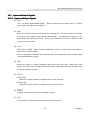
2 .3 .3
Cutte
tter Layout
iDP-3420 tear bar position
: Approx. 21 mm
iDP-3421/3423 auto cutter cutting position : Approx. 22 mm
Cutting position
iDP-3420
: Approx. 21 mm
iDP-3421/23 : Approx. 22 mm
19
CITIZEN
iDP-3420/3421/3423 User’s Manual
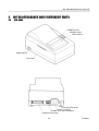
3.
3 .1
OUTER AP
APPEARA
ARANCE AN
AND COMPONENT PARTS
iDP-3420
3420
POWER Lamp
ERROR Lamp
FEED Switch
Power Switch
Top Cover
Grounding Terminal
Power Connector
Drawer Kick-Out Connector
Interface Connector
20
CITIZEN
iDP-3420/3421/3423 User’s Manual
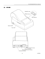
3 .2
iDP-3421
3421
POWER Lamp
ERROR Lamp
FEED Switch
Power Switch
Top Cover
Grounding Terminal
Power Connector
Drawer Kick-Out Connector
Interface Connector
21
CITIZEN
iDP-3420/3421/3423 User’s Manual
3 .3
iDP-3423
3423
POWER Lamp
ERROR Lamp
FEED Switch
Power Switch
Top Cover
Grounding Terminal
Power Connector
Drawer Kick-Out Connector
Interface Connector
22
CITIZEN
iDP-3420/3421/3423 User’s Manual
4.
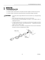
4 .1
OPERA
ERATION
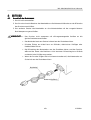
Conne
nnecting the Power Cord
1. Turn off the Power switch.
2. Connect a power cord connector to the power connector located on the back of the printer.
3. Connect a power cord plug to a plug socket where the specified voltage is available.
CAUTIONS : · Use the AC power supply different from the one used for any noise-generating
device.
· When disconnecting the power cord, be sure to hold its plug.
· Pulling the power cord could damage it and result in a fire, electric shock, or
snapping of the wire.
· If lightning has occurred in the nearby area, disconnect the power cord from
the plug socket and refrain from using the printer.
A lightning strike could
result in a fire or electric shock.
· When the printer is not used for a long period of time, be sure to disconnect
the power cord from the plug socket for safety.
Power Cord
Power
Connector
23
CITIZEN
iDP-3420/3421/3423 User’s Manual
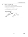
4 .2
Conne
nnecting the Interface Cable
1. Turn off the power. (Mating side included)
2. Check the top and bottom of the cable terminals, and connect to the interface connector.
3. Secure the cable terminals.
Serial interface
: Tighten screws to secure.
Parallel interface : Turn clamps to secure.
4. Connect the interface cable to the computer.
Serial Interface Cable
Serial Interface Connector
Clamp
Parallel Interface Connector
Parallel Interface
24
CITIZEN
iDP-3420/3421/3423 User’s Manual
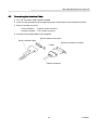
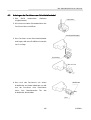
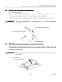
4 .3
Atta
ttaching the Fer rite Core to the Interface Cable
1. Turn off the power.(Mating side included)
Ferrite Core
2. With a regular screwdriver, unlatch and
open the ferrite core.
Interface Cable
3. Attach the ferrite core to the interface
cable so that its end face will be within up
to 5 cm.
Ferrite Core
Within 5 cm
4. Secure the arm of the ferrite core onto the
Fastener
cable with a fastener so that the ferrite
core will not move.
Cut off the surplus
part of the fastener.
Arm
25
CITIZEN
iDP-3420/3421/3423 User’s Manual
4 .4
Conne
nnecting the Drawer Kick-Out Conne
nnector
1. Turn off the power.
2. Check the top and bottom of the drawer kick-out cable connector and connect it to the
drawer kick-out connector located on the back of the printer.
3. Screw the grounding cable of the drawer to the grounding terminal of the printer.
CAUTION:·Connect only the prescribed drawer (Solenoid) to the drawer kick-out connector.
Drawer Kick-Out Connector
Drawer Kick-Out Cable Connector
Earth Terminal
4 .5
Opening/Closing the Auto Cutte
tter (iDP-342
3421/3423)
3423)
The auto cutter is secured by a magnet. Hold the auto cutter and turn it in the arrowindicated direction to open/close it.
CAUTION:·When closing the auto cutter, do so gently not to give a shock.
Auto Cutter
26
CITIZEN
iDP-3420/3421/3423 User’s Manual
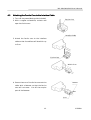
4 .6
Setti
tting the Cassette
tte Ribbon
(1) Open the printer cover.
(2) Open the auto cutter. (iDP-3421/3423)
(3) If the ribbon is slackened, turn the knob in the arrow-indicated direction to give the tension
to it before setting.
(4) While putting the ribbon in between the head cover and platen, push the locking claws into
the holder of the printer.
(5) Turn the knob of the cassette ribbon in the arrow-indicated direction to eliminate slackness
of the ribbon.
(6) To remove the cassette ribbon, lift it while tilting the locking claws on both sides toward the
inside.
(7) Close the auto cutter. (iDP-3421/3423)
CAUTION:·When closing the auto cutter, do so gently not to give a shock.
Ribbon
Cassette Ribbon
Head Cover
Knob
Platen
Locking Claw
27
CITIZEN
iDP-3420/3421/3423 User’s Manual
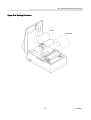
4 .7
Inserting the Paper
4.7.1 Inserting the Paper (iDP-3420/
3420/3421)
3421)
(1) Put your hands in the concave parts on both sides of the printer cover, and open it until it
comes to a stop.
(2) Cut the end of the paper roll at close to a right angle.
CAUTION : · Be sure to use the specified paper roll.
· Use of unspecified paper may adversely affect print quality, printer service life,
and so on.
· The printer cover is not detachable. Do not apply an excessive force beyond
its stopping position.
· Do not insert a frayed or bent end of paper into the printer.
(3) Check the winding direction of the paper roll.
(4) Opening the paper holder, support the center of the paper roll correctly.
(5) Turn on the printer.
(6) Insert the end of the paper roll straight into the paper inlet slot (Indicated by an arrow
on the case).
(7) The paper is automatically fed in and comes out the paper outlet of the printer (Paper
outlet of the auto cutter for the iDP-3421).
(8) iDP-3420: Put the paper into the paper outlet of the printer cover, close the cover, and
cut the surplus paper by the tear bar.
iDP-3421: Cut the surplus paper by the tear bar at the paper outlet of the auto cutter
and close the printer cover.
CAUTION : · If the paper is slack, rewind it, to remove the slack.
· If the paper is set slantwise, operate the paper-free lever, to correct the paper
position.
· While printing, do not hold the paper. This can cause a paper jam.
· When closing the auto cutter, do so gently not to give a shock.
28
CITIZEN
iDP-3420/3421/3423 User’s Manual
Paper Roll Setti
tting Direction
Good
No Good
29
CITIZEN
iDP-3420/3421/3423 User’s Manual
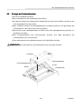
4 .7 .2
Inserting the Paper Roll (Duplic
licable 2-shee t Paper) (i
(iDP-3423
423)
1.
See Steps 1 to 6 in 4.7.1 Inserting the Paper.
2.
Press the FEED switch to feed the paper until the end of the paper comes out of the
paper outlet port of the auto cutter by about 25 cm.
3.
Open the auto cutter and pull out the paper roll from it.
4.
Thread the journal paper (Copying paper) between the auto cutter and platen.
5.
Thread the receipt paper (Original paper) tightly through the auto cutter, close the
cutter, and cut the surplus receipt paper by the tear bar.
6.
Insert the end of the journal paper into the slot in the winding reel and set onto the reel
holder.
7.
Turn the winding reel to tighten the receipt paper.
8.
Close the printer cover.
CAUTIONS : · If the paper is still slackened, wind it back to eliminate slackness.
· If the paper is set slantly, operate the paper free lever to correct a paper
position.
· Do not hold the paper while printing. It could cause a paper jam.
· When closing the auto cutter, do so gently not to give a shock.
Journal Paper
Auto Cutter
Winding Reel
Winding
Direction
Receipt Paper
Printer Mechanism
Paper Roll
(Duplicable 2-sheet Paper)
Paper Path (Duplicable 2-sheet Paper) Illustration Drawing
30
CITIZEN
iDP-3420/3421/3423 User’s Manual
4 .7 .3
Removing the Wound Paper Roll (iDP-3423)
423)
1.
Open the printer cover.
2.
Remove the paper roll by cutting it halfway or pushing the paper free lever in the arrowindicated direction.
3.
Detach the winding reel.
4.
Pull out a flange from one side of the winding reel.
5.
Pull out the paper roll from the winding reel.
Flange
Winding Reel
Paper Roll (Receipt Paper)
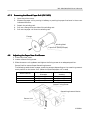
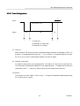
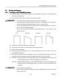
4 .8
Adjusting the Paper Near End Sensor
1. Close the printer cover.
2. Loosen a sensor fixing screw.
3. Slide the sensor unit up/down and tighten the fixing screw at an adequate position.
Sensor Position versus Paper Remaining Amount
The following table shows a paper remaining amount depending on the remaining amount
mark position on the sensor unit. (When the specified paper roll is used)
Mark Position
1
2
3
Paper Roll Remaining
Diameter
Approx. f21 mm
Approx. f23 mm
Approx. f25 mm
Paper Roll Remaining
Amount
Approx. 1.2 m
Approx. 2.2 m
Approx. 3.2 m
Sensor Fixing Screw
Remaining Amount Marks
Sensor Unit
31
CITIZEN
iDP-3420/3421/3423 User’s Manual
4 .9
How to Remove Remaining Paper Roll
(1) Open the printer cover.
(2) Open the auto cutter. (iDP-3421/3423)
(3) Pushing the paper-free lever in the arrow direction, pull out the paper roll.
(4) Close the auto cutter. (iDP-3421/3423)
CAUTION :·When pulling out the paper (Forward/Reverse direction), be sure to operate the
paper-free lever.
·When closing the auto cutter, do so gently not to give a shock.
Paper-Free Lever
4.10 Removing Paper Jam
(1) Open the printer cover.
(2) Cut off the paper near the paper inlet slot.
(3) Push the paper-free lever in the arrow direction.
The paper feed roller is disengaged, to
free the paper, allowing you to eliminate the jammed paper.
(4) Eliminate completely the paper remaining in the paper route.
CAUTION :·When pulling out the paper (Forward/Reverse direction), be sure to operate the
paper-free lever.
32
CITIZEN
iDP-3420/3421/3423 User’s Manual
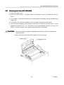
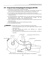
4.11
Unlocking the Cutter (iDP-3421/
421/3423)
23)
1. Open the printer cover.
2. Press the FEED switch.
The auto cutter is initialized to return its blade and clear an
alarm.
3. If the paper is jamming, eliminate the jamming paper completely, seeing "4.9 Removing
Paper Jam."
4. If the alarm still cannot be cleared, turn off the power and open the auto cutter.
5. You can see an emergency knob through a small hole in the back of the auto cutter. Using
tweezers, screwdriver, etc., turn the knob in the arrow-indicated direction to return the
blade. If there is a paper jam or paper refuse, eliminate it completely.
CAUTION:· When pulling out the paper(Forward/Reverse direction), be sure to operate the
paper free lever.
· When closing the auto cutter, do so gently not to give a shock.
Auto Cutter
Emergency Knob
33
CITIZEN
iDP-3420/3421/3423 User’s Manual
4.12 Operation Panel and Display of Er ror
1. POWER lamp (Green)
This lamp is illuminated when the power is supplied.
2. ERROR lamp (Red)
This lamp is illuminated or blinks to indicate each error.
Error Indication
Mechanical Error
ERROR Lamp
Quick blinking
Paper End
Illuminated
Paper Near End
Blinks
(Once a second)
Cutter Motor Lock
(iDP-3421/23 only)
Quick blinking
(Twice a second)
Buzzer
Sounds continuously for
approx. 1 second
Repeats a short 3-time
sound
twice
at
intervals of 0.5 second.
Repeats a short 3-time
sound
twice
at
intervals of 0.5 second.
Sounds
continuously
for approx. 1 second.
Resetting Method
Reset the Power
switch.
Set a new paper roll.
Set a new paper roll.
Eliminate a paper
jam.
Mechanical Error
: If the printer mechanism has a greater load due to a paper jam, etc.,
the buzzer will sound and the ERROR lamp will blink to stop the
printer mechanism.
Paper End
: If the paper has run out, the paper sensor in the paper path near the
print head will detect the end of the paper roll, turn on the buzzer,
and illuminate the ERROR lamp to stop the printer mechanism. If
the paper is inserted into the paper path, the paper roll will be loaded.
(See 4.7 Inserting the Paper)
Paper Near End
: If the paper is running out, the paper near end sensor will be
activated to turn on the buzzer and make the ERROR lamp blink.
Even after the paper near end is detected, a command can be used to
print by the specified number of lines. (See a description on the
command for setting the number of print lines after paper near end
detection)
Cutter Motor Lock : If the cutter position detection sensor in the cutter unit is left turned
(iDP-3421/23 only)
on or off for approx. 1 second while the cutter motor is running, cutter
operation and printing will be suspended, determining it to be motor
lock.
3. FEED switch
If this switch is pressed once for a short time, the paper will
be fed by 1 line. If it is held down, the paper will be fed
continuously.
POWER Lamp
4. FEED switch and Power switch
When the power is turned on, the printer follows the
operation flow at "power-on" on the next page, depending on
how the FEED switch is operated.
FEED Switch
34
ERROR Lamp
CITIZEN
iDP-3420/3421/3423 User’s Manual
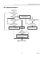
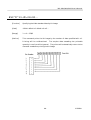
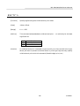
4.13 Operation Flow at Power-on
Power-on
OFF
Feed SW ?
ON
Buffer data
YES
NO
1 Sec. Passed
"Clear Data in Buffer"
Yes(FEED SW) and
Enlarged Red Print
NO
1 Sec. Passed
NO
YES
OFF
YES
OFF
FEED SW ?
(CONTINUE)
ON
FEED SW ?
(AGAIN)
ON
Prints "=Hexadecimal
Dump=." Dump Mode
est Print
Buffer Data
Input Buffer Clear
NO
YES
rints "Power Down(Data
n Buffer)" in Red, Followed
y Buffer Contents.
Waits for Data Input
35
CITIZEN
iDP-3420/3421/3423 User’s Manual
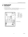
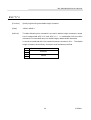
5.
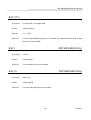
5 .1
DIP SWITCH SETTING
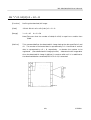
Location of DIP Switch
1. Turn off the power.
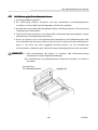
2. Open the printer cover.
3. If the paper roll has been set, remove it from the paper holder.
4. Detach the DIP switch cover.
The DIP switch can be found at the location shown in the
figure below. (Only DS1 is available for the parallel interface)
DIP Switch Cover
36
CITIZEN
iDP-3420/3421/3423 User’s Manual
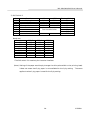
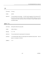
5 .2
DIP Switches Setti
tting
1) DIP Switch 1
No.
Function
ON
OFF
DS1-1
Auto cutter
Yes
No
DS1-2 International characters
²
DS1-3
See the Table below
²
DS1-4
DS1-5
Paper used
2P
1P
DS1-6
CR mode
See the Table below
DS1-7
Columns
42 columns
40 columns
DS1-8
Buffer size
6K bytes
256 bytes
DS1-9
Operation mode
See the table below
²
DS1-10
*1, *3 : Depends on the type.
*2
: Depends on the destination.
International Character Selection
No.
ON *1
ON *2
ON *2
ON *2
OFF
OFF
ON
ON
OFF *3
OFF *3
Character Code Selection
DS1-2
DS1-3
DS1-4
U.S.A.
ON
ON
ON
France
Germany
U.K.
Denmark
Sweden
Italy
OFF
ON
OFF
ON
OFF
ON
ON
OFF
OFF
ON
ON
OFF
ON
ON
ON
OFF
OFF
OFF
Japan
OFF
OFF
OFF
ountry
Upon Shipment from Factory
ESC/POS
mode
CBM mode
²
²
²
²
²
²
²
²
²
²
Star mode
Star
CBM
Code 437 (International) (International)
Code 850
Code 850
Code 850
Katakana
CBM
(Japanese)
²
²
²
²
²
Star
(Japanese)
See the International Character Codes Table and Character Codes Table.
CR mode(DS1-6)
Mode
CBM
STAR
ESC/POS
OFF
CR+LF
CR+LF
CR+LF
Operation Mode
ON
CR
Ignored
CR
CBM
ESC/POS
STAR
STAR Auto cut
37
DS1-9
OFF
ON
OFF
ON
DS1-10
OFF
OFF
ON
ON
CITIZEN
iDP-3420/3421/3423 User’s Manual
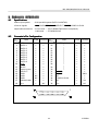
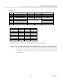
2) DIP Switch 2
No.
DS2-1
DS2-2
DS2-3
DS2-4
DS2-5
DS2-6
DS2-7
DS2-8
Function
Bit length
Parity
Odd/Even
Communication mode
Baud rate
ON
8 bits
No
Odd
DTR/DSR
²
²
Unused
OFF
7 bits
Yes
Even
XON/XOFF
See the table below
-
-
Factory Setting
ON
ON
ON
ON
ON
ON
OFF
OFF
Baud rate
Baud rate
150
300
600
1200
2400
4800
9600
19200
DS2-5
OFF
OFF
OFF
OFF
ON
ON
ON
ON
DS2-6
OFF
OFF
ON
ON
OFF
OFF
ON
ON
DS2-7
OFF
ON
OFF
ON
OFF
ON
OFF
ON
*The DIP switch 2 is used only for the serial interface.
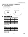
(Note) Setting of the paper used simply changes the drive pulse width to the printing head;
it does not mean that 2-ply paper is not available for the 1-ply setting.
The same
applies to when 1-ply paper is used for the 2-ply setting.
38
CITIZEN
iDP-3420/3421/3423 User’s Manual
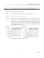
6. PRES
RESET JUMPER SETTI
TTING
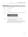
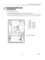
6 .1
Location of Preset Jumper
(1) Turn off the power.
(2) Remove a cassette ribbon.
(3) Remove the top cover. The preset jumper is located as shown in the figure below.
Serial Interface
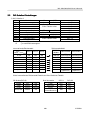
6 .2
Parallel Interface
Preset Jumper Table
Serial
Mode
Location
SCA
SCB
SCC
SCD
SCE
SCF
SCG
SCH
CBM
STAR
ESC/POS
1-C *
1-C *
1-C
1-C
1-C *
1-C *
1-C *
1-C
2-C
1-C *
2-C
2-C
2-C
2-C
2-C
2-C *
2-C
2-C
*
*
1-C *
1-C *
1-C *
2-C *
CBM
STAR
ESC/POS
1-C *
1-C
1-C *
1-C
1-C
1-C
1-C *
1-C
2-C *
2-C
2-C
2-C *
* = Open
1-C * = 1-C or open
2-C * = 2-C or open
Parallel
Mode
Location
SCA
SCB
SCC
SCD
* = Open
1-C * = 1-C or open
2-C * = 2-C or open
39
CITIZEN
iDP-3420/3421/3423 User’s Manual
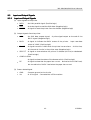
7.
MODE SETTI
TTING METHOD
This printer has the CBM, STAR, and ESC/POS mode. Any desired mode can be selected and
set according to your need.
(1) Setting method
· See 5. DIP SWITCH SETTING.
· Seeing the settings of the DIP switch segments 1-9 and 1-10 and those of the preset
jumper, set each mode.
40
CITIZEN
iDP-3420/3421/3423 User’s Manual
8.
8 .1
INPUT BUFFE
FFER BACK
ACKUP FUNCTION
Buffer Size
With the DIP switch, you can set either 6 K bytes or 256 bytes.
DIP switch segment 1-8
ON
® 6K bytes
OFF ® 256 bytes
8 .2
Input Buffer Backup
Even if the power is turned off or fails during the printing process, the data in the input buffer
will be saved.
If the power is turned on again, the printer will print a power failure mark,
"==POWER DOWN==," in red and reprints the data from the beginning of the line where it
left off.
8 .3
Clearing the Input Buffer
When you want to clear the data in the input buffer, turn on the power, holding down the LF
switch. A buzzer will sound to inform you that the input buffer has been cleared. Hold down
the LF switch until the buzzer sounds.
If the printer prints the data erroneously at power-on, clear the input buffer as described
above, and then, re-input the data.
41
CITIZEN
iDP-3420/3421/3423 User’s Manual
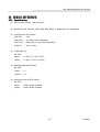
9. PARALLE
LLEL INTERFACE
9 .1
Specifications
·Data input system
: 8-bit parallel system (DATA1 to DATA8)
·Control signals
: ACK, BUSY, STB, FAULT, SELECT, RESET, COMPULSION
·Applicable connectors : Printer side --- 57LE-40360 (Equivalent to anphenol),
Cable side
9 .2
--- 57-30360 (Ditto)
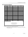
Conne
nnector's Pin Configuration
Mode
No.
1
2
3
4
5
6
7
8
9
10
11
12
13
14
15
16
17
18
CBM
STB
DATA 1
DATA 2
DATA 3
DATA 4
DATA 5
DATA 6
DATA 7
DATA 8
ACK
BUSY
PE(HI-LEVEL)
SELECT
GND
GND
GND
FRAME GND
Vcc
Mode
STAR ESC/POS No.
19
¬
¬
20
¬
¬
21
¬
¬
22
¬
¬
23
¬
¬
24
¬
¬
25
¬
¬
26
¬
¬
27
¬
¬
28
¬
¬
29
¬
¬
30
¬
¬
31
¬
¬
32
¬
¬
NC
33
¬
NC
34
¬
35
¬
¬
NC
36
¬
42
CBM
TWISTED PAIR GND
RESET
FAULT
NC
COMPULSION
NC
Vcc
STAR ESC/POS
¬
¬
¬
¬
¬
¬
¬
¬
¬
¬
¬
¬
¬
¬
¬
¬
¬
¬
¬
¬
¬
¬
¬
¬
¬
¬
¬
¬
¬
¬
¬
GND
¬
¬
Vcc
NC
CITIZEN
iDP-3420/3421/3423 User’s Manual
9 .3
Input and Output Signals
9.3.1 Input and Output Signals
(1) Input signals to the printer
· DATA
: An 8-bit parallel signal. (Positive logic)
· STB
: A strobe signal to read the 8-bit data. (Negative logic)
· RESET
: A signal to reset the printer from the outside. (Negative logic)
(2) Output signals from the printer
· ACK
: An 8-bit data request signal.
A pulse signal output at the end of the
BUSY signal. (Negative logic)
· BUSY
: A signal to indicate the BUSY status of the printer.
Input new data
when at "LOW". (Positive logic)
· FAULT
: A signal turned to "LOW" when the printer has an alarm.
At this time,
all the control circuits in the printer stop. (Negative logic)
· SELECT : A signal to show whether the printer is selected (On-line) or deselected.
(Positive logic)
· COMPULSION
: A signal to show the status of the drawer switch. (Positive logic)
· PE
: A signal to show that the paper has run out. Normal at the "LOW" level,
but turned to the "HIGH" level when the paper has run out.
(3) Power related signal
· GND
: Common ground on the circuits
· Vcc
: A +5 V signal. Connected via a 3.3kW resistor.
43
CITIZEN
iDP-3420/3421/3423 User’s Manual
9 .3 .2
Electrical Characteristics
(1) Input signal level
All the input signals are at the TTL level.
"HIGH" level: 2.0 V at minimum
"LOW" level : 0.8 V at maximum
(2) Output signal level
All the output signals are at the TTL level.
"HIGH" level: 2.4 V at minimum
"LOW" level : 0.4 V at maximum
(3) Input and output conditions
All the input signals are pulled up at 3.3 kW.
[Printer Side]
[Host Side]
Twisted Pair Wire
All the output signals are pulled up at 3.3kW.
[Printer Side]
[Host Side]
Twisted Pair Wire
44
CITIZEN
iDP-3420/3421/3423 User’s Manual
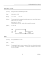
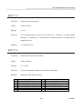
9 .3 .3
Timing Char t
(1) Data input and printing timing
T1, T2, T3 : 0.5 ms MIN
9 .3 .4
T4
: 270 ns MAX
T5
: 2.3ms TYP
T6
: 500 ms MIN (At power-on)
Data Receiving Control
When the BUSY signal is at "LOW," the printer can receive the data from the host, but when
at "HIGH," it cannot.
45
CITIZEN
iDP-3420/3421/3423 User’s Manual
10.
10. SERIAL INTERFACE
ACE
10.
10.1 Specifications
(1) Synchronous system: Asynchronous
(2) Baud rate: 150, 300, 600, 1200, 2400, 4800, 9600, or 19200 bps (User selectable)
(3) Configuration of one word
·Start bit
: 1 bit
·Data bits
: 7 or 8 bits (User selectable)
·Parity bit
: Odd, even, or none (User selectable)
·Stop bit
: 1 bit or more
(4) Signal polarity
RS-232C
·Mark
= Logic "1" (-3 V to -12 V)
·Space
= Logic "0" (+3 V to +12 V)
(5) Received data (RXD signal)
RS-232C
· Mark
= 1
· Space
= 0
(6) Reception control (DTR signal)
RS-232C
·Mark
: Data transfer disabled
·Space
: Data transfer enabled
46
CITIZEN
iDP-3420/3421/3423 User’s Manual
10.
10.2 Conne
nnector's Pin Configuration
No.
Mode
1
2
3
4
5
6
7
8
9
10
11
12
13
14
15
16
17
18
19
20
21
22
23
24
25
CBM
STAR
ECS/POS
FG
TXD
RXD
¬
¬
¬
¬
¬
¬
¬
RTS
DSR
GND
¬
PE (HI-LEVEL)
FAULT
RCH
¬
GND
FAULT
mTXD
mRXD
DTR
¬
¬
RESET
Cautions: 1. An RS-232C signal is based on the EIA RS-232C.
2. When the data is not being transferred, the received data should be always
maintained as a mark.
47
CITIZEN
iDP-3420/3421/3423 User’s Manual
10.
10.3 Input and Output Signals
10.
10.3.1 Input and Output Signals
(1) RXD
This is a serial received data signal.
When a framing error, overrun error, or parity
error occurs, that data is printed as "?".
(2) DTR
When this signal is Ready, write the data or a command. If written at the time of Busy,
an overrun error results, ignoring the previous data.
input buffer even during printing.
The data can be written in the
Busy is also issued at the time of power-on, test
print, on-line, and reset.
(3) TXD
XON (11H) or XOFF (13H) is sent at XON/XOFF control.
XON (11H) is sent every 3
seconds in the STAR mode.
When a command is received, that requests the printer state and printer status, 1-byte
corresponding data is output.
(4) DSR
When this signal is a space, the data is sent from the printer side.
Note that if this
signal is a mark when a request to send command is executed, the printer will wait until
the signal becomes a space.
(5) FAULT
1 CBM mode
When this signal is Space, a mechanical error has occurred.
2 STAR mode
When this signal is Mark, a mechanical error has occurred.
(6) RESET
A signal to reset the entire printer. (Negative logic)
(7) RTS
This signal is turned to Space when the printer is turned on.
48
CITIZEN
iDP-3420/3421/3423 User’s Manual
(8) RCH
When the printer is ready to receive, this signal is turned to Space.
This signal line is
the same as DTR.
(9) mTXD
TXD signal for the diode gate.
(10) mRXD
RXD signal for the diode gate.
(11) FG
This is a Frame Ground signal.
(12) GND
This is a common ground on the circuit.
49
CITIZEN
iDP-3420/3421/3423 User’s Manual
10.
10.3.2 Data Configuration
t
Mark
b0, b1, b2, · · · ·
Space
(1)
(2)
(3)
(1) Start Bit
(2) Data Bit (+ Parity Bit)
(3) Stop Bit (1 or More)
(1) Start bit
After a lapse of 1/2 bit from a mark-to-space fall edge, the state is read again, and if it is
a space, it is recognized as the start bit.
If it is a mark, it is assumed neither the start
bit nor an error, and it is attempted to detect the start bit again.
(2) Data bit + parity bit
The data bit and parity bit are sampled for 1 bit worth of time from the 1/2 start bit.
The then state is assumed the data for the corresponding bit. A sequence of the bits are
named Bit 0, Bit 1, ..., parity bit, starting from the one closest to the start bit.
(3) Stop bit
The stop bit is a mark level of 1 bit or more. If a space is detected in detecting the stop
bit, a framing error results.
50
CITIZEN
iDP-3420/3421/3423 User’s Manual
10.
10.3.3 Er ror Detection
A parity error, framing error, and overrun error are detected.
When an error is detected,
that data is stored in the buffer as "?".
(1) Framing error
This error results when a space is detected in detecting the stop bit. That data is stored
in the buffer as "?".
(2) Parity error
If a parity check has been specified and an error is detected at the time of parity check,
that data is stored in the buffer as "?".
(3) Overrun error
If an overrun error is detected, that data is stored in the buffer as "?".
10.
10.3.4 Data Receiving Control
When the DTR signal is a space, the data from the host side can be received.
When it is a
mark, however, the data cannot be received.
10.
10.3.5 Buffering
The DTR and TXD signals are available as control signals to transfer the data to the input
buffer.
51
CITIZEN
iDP-3420/3421/3423 User’s Manual
10.
10.3.6 Electrical Characteristics
(1) RS-232C circuit
Input (RXD, DSR, mRXD)
[Printer Side]
[Host Side]
RXD
Mark=(-8V): Stop bit
Space=(+8V): Start bit
Equivalent MAX232
Output (DTR, TXD, mTXD, RCH, RTS, FAULT)
Equivalent to MAX232
DTR
Mark=(-8V): At Busy
TXD
Space=(+8V): At Ready
Mark=(-8V): 1
Space=(+8V): 0
(2) Others
·RESET
: A signal to reset the entire printer.
·PE
: A signal to show that the paper has run out.
Normal at the "LOW" level,
but turned to the "HIGH" level when the paper has run out.
·GND
: Signal ground
·FG
: Frame ground
52
CITIZEN
iDP-3420/3421/3423 User’s Manual
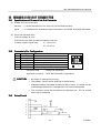
11. DRAWER KICK-OUT CONNE
NNECTOR
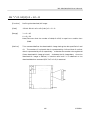
11.1
Specifications of Drawer Kick-Out Conne
nnector
(1) Drawer kick-out drive signal
Parallel ----- Can be learned at the no. 34 pin of the interface connector
Serial
----- Provided with a command to learn the status in the STAR and ESC/POS modes.
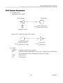
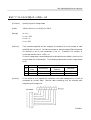
(2) Electrical characteristics
1) Drive voltage: 24 V DC
2) Drive current: 0.8 A at maximum (Within 510 ms)
3) Switch signal: Signal level
"L" = 0 to 0.5 V
"H" = 3 to 5 V
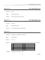
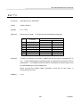
11.2
Conne
nnector's Pin Configuration
No.
1
2
3
4
5
6
Signal
FG
DRAWER 1
DRSW
VDR
DRAWER 2
GND
Function
Frame Ground
Drawer 1 drive signal
Drawer switch input
Drawer drive power
Drawer 2 drive signal
Common ground on the circuit
Connector used
: TM5RJ3-66 (HIROSE)
Applicable connector : TM3P-66P (HIROSE) or equivalent
CAUTION : · No output is made while printing.
· The drawers 1 and 2 cannot be driven simultaneously.
· A solenoid used for the drawer should be of 36W or more. An output current
should be kept below 0.8 A. Use beyond this limit cannot be assured.
· This connector cannot be connected to a telephone line. Do not connect
other than the solenoid.
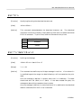
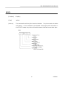
11.3
Drive Circuit
53
CITIZEN
iDP-3420/3421/3423 User’s Manual
12.
12. MAINTENANCE AN
AND SERVICE
For the information on maintenance and service, please contact our dealer or at the following
address.
Northern America
Other Areas
CBM America Corporation
Japan CBM Corporation
Service Center
Information Systems Division
365 Van Ness Way
CBM Bldg., 5-68-10, Nakano
Suit 510
Nakano-ku, Tokyo 164-0001
Torrance, CA 90501, U.S.A
Japan
TEL +1-310-781-1460
TEL +81-3-5345-7540
FAX +1-310-781-9157
FAX +81-3-5345-7541
54
CITIZEN
iDP-3420/3421/3423 User’s Manual
13.
13. PRINT CONTROL FUNC
UNCTIONS
13.
13.1
CBM Mo
Mode
13.
13.1.1 Comma
mmand List
1
2
3
4
5
6
7
8
9
10
11
12
13
14
15
16
17
18
19
20
21
22
23
24
25
26
27
28
29
30
31
Command
FF n
SO
SI
LF
CR
DC 1
DC 2
DC 3
CAN
ESC * n1 n2
ESC - n
ESC 1
ESC 2
ESC 3
ESC C n
ESC N n
ESC O
ESC f 1
ESC t n
ESC BEL n1 n2
BEL
FS
SUB
RS
ESC P 0
ESC P 1
ESC R 1
ESC & 0 n1 n2
ESC % n
ESC ¤ n
ESC DC3 n
32 ESC y n
33 ESC DC2 n1 n2
34 GS * n1 n2
35 GS ¤ m
Function
n-line paper feed
Specifying the double width character
Canceling the double width character
Printing and paper feed
Printing
Initializing the printer
Specifying/Canceling the Inverted character
Specifying the red print
Canceling the print data
Specifying the bit image mode
Specifying/Canceling the Underline
Specifying 1/9-inch line feed rate
Specifying 2/9-inch line feed rate
Specifying 1/6-inch line feed rate
Setting the page length
Specifying the perforation skip
Canceling the perforation skip
Form feed (Changing the page)
Selecting the character code table
Setting the external device drive pulse width
Driving command A for Drawer-1
Driving command B for Drawer-1
Driving command for Drawer-2
Buzzer-on
Full cut
Partial cut
Selecting the international character set
Defining the download character set
Specifying/Canceling download character set
Definition the message
Printing the message
Setting the print lines after paper near end
detection
Deleting the download character, message,
bit image
Defining the download, bit image
Printing the download, bit image
55
Code
1BH 25H n
1BH 2FH n
1BH 13H n
Page
56
56
57
57
57
58
58
59
59
60
60
61
61
61
61
62
62
62
63
64
64
65
65
65
66
66
66
67
68
68
69
1BH 79H n
69
1BH 12H n1 n2
70
1DH 2AH n1 n2
1DH 2FH m
71
72
0CH n
0EH
0FH
0AH
0DH
11H
12H
13H
18H
1BH 2AH n1 n2
1BH 2DH n
1BH 31H
1BH 32H
1BH 33H
1BH 43H n
1BH 4EH n
1BH 4FH
1BH 66H 01H
1BH 74H n
1BH 07H n1 n2
07H
1CH
1AH
1EH
1BH 50H 00H
1BH 50H 01H
1BH 52Hn
1BH 26H 00H n1 n2
CITIZEN
iDP-3420/3421/3423 User’s Manual
13.
13.1.2 Descri
cription of Items
XXXX
ALL
[Function]
Command name
[Code]
A row of command constituent code is represented by a hexadecimal number with
< >H, binary number with < >B, and a decimal number with < >.
[ ]k means a
repeat count of k-times.
[Range]
Describes an argument value (Setting range) for the command.
[Outline]
Describes a command function.
[Caution]
Describes a caution as required.
[Default]
Describes an initial value for the command when accompanied by an argument.
XXX
Shows a command.
56
CITIZEN
iDP-3420/3421/3423 User’s Manual
Details
ils
FF n
[Function]
n-line paper feed
[Code]
<0C>H n
[Range]
1 £ n £ 127
[Outline]
This command feeds the paper by n-lines. You can set n = 1 to 127 lines. If the
print buffer contains the data, use of this command feeds the paper by n-lines
after printing the data. Setting n = 0 does not feed the paper.
SO
[Function]
Specifying the double width character
[Code]
<0E>H
[Outline]
The data following this command is printed doubled in the horizontal direction.
Double width characters remain valid until the double width character cancel
command is entered, but they are also cancelled after they are printed one line.
Note that the double width characters take up two ordinary characters worth of
width.
57
CITIZEN
iDP-3420/3421/3423 User’s Manual
SI
[Function]
Canceling the double width character
[Code]
<0F>H
[Outline]
This command cancels the double width characters set with SO.
The data
following this command are printed in the ordinary character width.
LF
[Function]
Printing and paper feed
[Code]
<0A>H
[Outline]
If the print buffer contains the data, this command will feed the line after
printing. If not, the command only feeds the line.
CR
[Function]
Printing
[Code]
<0D>H
[Outline]
This command prints the data. If the DIP switch segments 1 to 6 are set to OFF,
the printer will print the data in the print buffer and feed the paper by one line.
If they are set to ON, the printer will print the data in the print buffer and will
not feed the paper.
58
CITIZEN
iDP-3420/3421/3423 User’s Manual
DC1
[Function]
Initializing the printer
[Code]
<11>H
[Outline]
This command initializes the printer.
The input buffer is not cleared.
The settings of the DIP switch segments are not re-read.
DC2
[Function]
Specifying/Canceling the inverted character
[Code]
<12>H
[Outline]
This command selects/deselects the inverted characters. Enter this command at
the beginning of one line.
Otherwise, it is overridden.
Erect and inverted
characters cannot be mixed in one line.
59
CITIZEN
iDP-3420/3421/3423 User’s Manual
DC3
[Function]
Specifying the red print
[Code]
<13>H
[Outline]
This command specifies red-color characters. All the characters in one line are
printed in red by prefixing the print data with this command and sending it to
the printer.
When you want to use red characters, use this command for each
line.
CAN
[Function]
Canceling the print data
[Code]
<18>H
[Outline]
This command clears the print data in the lines entered prior to this command.
60
CITIZEN
iDP-3420/3421/3423 User’s Manual
ESC "*" n1 n2
[Function]
Specifying the bit image mode
[Code]
<1B>H <2A>H n1 n2
[Range]
1 £ n1 + 256 ´ n2 £ 378
[Outline]
This command allows printing in the bit image mode. Divide the number of dots
printed by 256 and assume its quotient to be n2 and remainder to be n1.
Therefore, the number of horizontal dots will be n1 + 256 ´ n2.
If the bit image data is entered beyond the dot positions printable in one line, the
surplus data will be discarded.
Normal data processing is restored after bit
image printing. Printing is done in a single direction.
ESC "-" n
[Function]
Specifying/Canceling the underline
[Code]
<1B>H <2D>H n
[Outline]
This command selects/deselects an underline. The underline is selected at n = 1
and deselected at n = 0.
[Default]
n=0
61
CITIZEN
iDP-3420/3421/3423 User’s Manual
ESC "1"
[Function]
Setting the 1/9-inch line feed width
[Code]
<1B>H <31>H
[Outline]
This command sets the line feed width to 1/9 inch.
ESC "2"
[Function]
Setting the 2/9-inch line feed width
[Code]
<1B>H <32>H
[Outline]
This command sets the line feed width to 2/9 inch.
ESC "3"
[Function]
Setting the 1/6-inch line feed width
[Code]
<1B>H <33>H
[Outline]
This command sets the line feed width to 1/6 inch(Default).
ESC "C" n
[Function]
Setting the page length
[Code]
<1B>H <43>H n
[Range]
1 £ n £ 127
[Outline]
Sets the 1-page length to n-lines.
62
CITIZEN
iDP-3420/3421/3423 User’s Manual
ESC "N" n
[Function]
Specifying the perforation skip
[Code]
<1B>H <4E>H n
[Range]
1 £ n £ 126
[Outline]
This command feeds(Skips) the lines specified with n without printing. However,
you cannot specify beyond the length of one page.
ESC "O"
[Function]
Canceling the perforation skip
[Code]
<1B>H <4F>H
[Outline]
This command cancels perforation skipping operation.
ESC "f" 1
[Function]
Form feed (Changing the page)
[Code]
<1B>H <66>H <01>H
[Outline]
This command searches for the beginning of the next page after printing the data
in the print buffer.
63
CITIZEN
iDP-3420/3421/3423 User’s Manual
ESC "t" n
[Function]
Selecting the character code table
[Code]
<1B>H <74>H n
[Range]
0 £ n £ 255
[Outline]
This command selects Page-n of Character Code Table.
[Default]
Depends upon DIP switch setting.
n
0
1
2
3
4
5
Character Code Table
CBM International
CBM Domestic
Code Page 850 (Multilingual)
Code Page 860 (Portugal)
Code Page 863 (Canada-French)
Code Page 865 (Norway)
n
6
7
8
9
Character Code Table
Code Page 852 (Eastern Europe)
Code Page 866 (Russia)
Code Page 857 (Turkey)
Windows Code
255 Space Page (For user setting)
64
CITIZEN
iDP-3420/3421/3423 User’s Manual
ESC BEL n1 n2
[Function]
Setting the external device drive pulse width
[Code]
<1B>H <07>H n1 n2
[Range]
1 £ n1 £ 127
[Outline]
This command sets the power-on time to drive an external device (Cash drawer).
1 £ n2 £ 127
Power-on time = n1 ´ 10 (ms)
Delay time = n2 ´ 10 (ms)
To actually drive the drawer, use the <BEL> and <FS> commands.
[Default]
n1 = n2 = 20
BEL
[Function]
Driving command A for drawer-1
[Code]
<07>H
[Outline]
This command drives the drawer connector no. 2 pin under the condition set with
the <ESC><BEL> n1 n2 command. This command is executed in order of entry
into the input buffer.
65
CITIZEN
iDP-3420/3421/3423 User’s Manual
FS
[Function]
Driving command B drawer-1
[Code]
<1C>H
[Outline]
This command drives the drawer connector No. 2 pin under the condition set with
the <ESC><BEL> n1 n2 command.
SUB
[Function]
Driving command for drawer-2
[Code]
<1A>H
[Outline]
As soon as this command is received, the drawer connector no. 5 pin is driven.
The power-on time is 200 ms ON and 200 ms OFF stationary.
The drawers 1
and 2 cannot be driven simultaneously.
RS
[Function]
Buzzer-on
[Code]
<1E>H
[Outline]
This command emits a short warning sound from the printer.
66
CITIZEN
iDP-3420/3421/3423 User’s Manual
ESC "P" 0
(iDP-3421/3423 only)
[Function]
Full cut
[Code]
<1B>H<50>H<00>H
[Outline]
This command fully cuts the paper.
ESC "P" 1
(iDP-3421/3423 only)
[Function]
Partial cut
[Code]
<1B>H<50>H<01>H
[Outline]
This command partially cuts the paper.
ESC "R" n
[Function]
Selecting the international character set
[Code]
<1B>H <52>H n
[Range]
0 £ n £ 10
[Outline]
This command selects the international characters according to the value of n.
n
0
1
2
3
4
5
[Default]
Character Set
U.S.A.
France
Germany
U.K.
Denmark I
Sweden
n
6
7
8
9
10
Character Set
Italy
Spain
Japan
Norway
Denmark II
Depends upon DIP switch setting.
67
CITIZEN
iDP-3420/3421/3423 User’s Manual
ESC "&" <0> n1 n2 [m0 m1 ... m5 m6 m7 m8 m9] n2 - n1 + 1
[Function]
Defining the Download character set
[Code]
<1B>H <26>H <00>H n1 n2 [m0 m1 ... m5 m6 m7 m8 m9] n2 - n1 + 1
[Range]
32 £ n1 £ n2 £ 255
[Outline]
This command defines he download characters.
m0 = 0 or m0 = 128
n1 is a character code to start
definition and n2 is to end definition, respectively.
character, set n1 = n2.
When defining only one
You can define the ASCII codes ranging from 32 to 255.
Once the download characters are defined, they remain valid until they are
redefined or the download deletion command (ESC DC2 n1 n2) is executed.
68
CITIZEN
iDP-3420/3421/3423 User’s Manual
ESC "%" n
[Function]
Specifying/Canceling the download character set
[Code]
<IB>H <25>H n
[Outline]
This command selects/deselects the download character set.
The download
characters cannot be printed by simply defining them with the above-mentioned
ESC & 0 command. To print them, send this command to the printer.
n
0
30
1
31
Download Character Set
Deselects
Selects
ESC "¤" n "data" CR or LF
[Function]
Defining the Message
[Code]
<1B>H <2F>H n "data" CR or LF
[Range]
1 £ n £ 10
[Outline]
This command can define up to a 50-byte message in one line.
If the value of n
is specified beyond the range, the data following n will be treated as the print
data.
Once the message is defined, it remains valid until it is redefined.
should end with CR (0DH) or LF (0AH).
The data
If the data exceeds 50 bytes, the
subsequent data will be treated as the print data.
Once the message is defined, it remains valid until it is redefined or the download
deletion command (ESC DC2 n1 n2) is executed.
69
CITIZEN
iDP-3420/3421/3423 User’s Manual
ESC DC3 n
[Function]
Printing the message
[Code]
<1B>H <13>H n
[Range]
1 £ n £ 10
[Function]
This command prints a message. If the value of n is specified beyond the range,
the message will not be printed.
ESC "y" n
[Function]
Setting the print lines after paper near end detection
[Code]
<1B>H<79>H n
[Range]
0 £ n1 £ 255
[Outline]
This command sets the number of print lines after paper near end detection.
It
stops printing after printing n ´ 2 lines since detection of the paper near end,
resulting in the paper near end state (See 4.12 Operation Panel and Error
Indications).
The PE signal (Serial/Parallel) changes when the paper near end
is detected.
[Default]
n=0
70
CITIZEN
iDP-3420/3421/3423 User’s Manual
ESC DC2 n1 n2
[Function]
Deleting the download character, message, bit image
[Code]
<1B>H <12>H n1 n2
[Range]
0 £ n1 £ 3
0 £ n2
(Specify 0 at n1 = 0)
(1 £ n2 £ 10 at n1 = 1)
(32 £ n2 £ 255 at n1 = 2)
(Specify 0 at n1 = 3)
[Outline]
This command deletes the downloaded characters, message, and bit image.
n1
0
1
2
3
Object Deleted
All(Message, characters, bit image)
Download message
Download characters
Download bit image
With n2, specify which data of the function specified with n1 should be deleted.
n2 = 0
Deletes all the data saved with the download function specified with n1.
n2¹0
Deletes the data downloaded at the value specified with n2 (Value
specified when saving with each download command), of the download
function specified with n1.
Note) No meaning when n1 = 0 is set.
71
CITIZEN
iDP-3420/3421/3423 User’s Manual
GS "*" n1 n2 [d] n1 ´ n2 ´ 8
[Function]
Defining the download, bit image
[Code]
<1D>H <2A>H <n1> <n2> [<d>] n1 ´ n2 ´ 8
[Range]
1 £ n1 £ 45
0 £ n2 £ 24
Note) Take care that the number of data (n1´n2´8) is equal to or smaller than
2,048.
[Outline]
This command defines the download bit image having the dots specified n1 and
n2.
The number of horizontal dots is represented by n1 ´ 8 and that of vertical
dots is represented by n2 ´ 8, respectively.
registered.
(See a download bit image printout.)
m denotes the number to be
d denotes the bit image data.
Once the download bit image is defined, it remains valid until it is redefined or
the download deletion command (ESC DC2 n1 n2) is executed.
72
CITIZEN
iDP-3420/3421/3423 User’s Manual
GS ¤ m
[Function]
Printing the download, bit image
[Code]
<1D>H <2F>H m
[Range]
0 £ m £ 255
[Outline]
This command prints the bit image saved in the number specified with m.
[Caution]
If the print buffer contains the data, this command will be ignored.
If the bit
image has not been saved in the specified number, this command will be ignored.
Nothing is printed when m is other than 0,1,2 or 3.
73
CITIZEN
iDP-3420/3421/3423 User’s Manual
13.
13.2
STAR Mode
13.
13.2.1 Comma
mmand List
1
2
3
4
5
6
7
8
9
10
11
12
13
14
15
16
17
18
19
20
21
22
23
24
25
26
27
28
29
30
31
32
33
34
35
36
37
38
39
40
Command
ESC R n
ESC 6
ESC 7
ESC M
ESC P
ESC :
SO
DC4
ESC E
ESC F
ESC ESC _
ESC 4
ESC 5
SI
DC2
LF
CR
ESC z
ESC 0
ESC a n
FF
ESC C n
ESC C 0 n
VT
ESC B n1 n2
ESC N n
ESC 0
ESC 1 n
ESC Q [n] k NUL
HT
ESC D n1 n2
ESC 1
ESC A n
ESC 2
ESC J n
ESC K n1 <0>
ESC L n1 n2
ESC h n
ESC & <0> n1 n2
41 ESC % n
Function
Selecting the international character set
NOP
NOP
NOP
NOP
NOP
Specifying the double width character
Canceling the double width character
Specifying the highlight character
Canceling the highlight character
Specifying/Canceling the underline
NOP
Specifying the red print
Canceling the red print
Specifying the inverted character
Canceling the inverted character
Printing and paper feed
Printing
Setting the 1/6-inch line feed
NOP
n-line paper feed
Form feed (Change the page)
Setting the n-line page length
Setting the n-inch page length
Vertical tab
Setting the vertical tab position
Setting the lower margin
Canceling the lower margin
Setting the left margin
Setting the right margin
Horizontal tab
Setting the horizontal tab position
Setting the 1/9-inch line feed width
NOP
Setting the 2/9-inch line feed width
NOP
Specifying the 8-dot standard density bit image
Specifying the 8-dot double density bit image
Specifying/Canceling the double height character
Defining the download character
Specifying/Canceling
the
character set
74
download
Code
1BH 52H n
1BH 36H
1BH 37H
1BH 4DH
1BH 50H
1BH 3AH
0EH
14H
1BH 45H
1BH 46H
1BH 2DH n
1BH 5FH n
1BH 34H
1BH 35H
0FH
12H
0AH
0DH
1BH 7AH
1BH 30H
1BH 61H n
0CH
1BH 43H n
1BH 43H 00 n
0BH
1BH 42H n1 n2
1BH 4EH n
1BH 4FH
1BH 6cH n
1BH 51H n
09H
1BH 44H n1 n2
1BH 31H
1BH 41H n
1BH 32H
1BH 4AH n
1BH 4BH n1 00H
1BH 4CH n1 n2
1BH 68H n
Page
75
75
76
76
76
77
77
77
78
78
79
79
79
80
80
80
81
81
82
82
83
83
83
84
85
86
86
1BH 26H 00H n1 n2
87
88
89
90
1BH 25H n
91
CITIZEN
iDP-3420/3421/3423 User’s Manual
42
43
44
45
46
47
48
49
Command
ESC BEL n1 n2
BEL
FS
SUB
RS
CAN
DC3
DC1
50 ESC U n
51
52
53
54
55
56
57
58
59
ESC @
ENQ
STX
ETX
ESC d 0
ESC d <0>
ESC d 1
ESC d <0>
ESC t n
ESC / n
ESC DC3
60 ESC y n
61 ESC DC2 n1 n2
62 GS * n1 n2
63 GS ¤ m
Function
Setting the external device drive pluse width
Driving command A for drawer-1
Driving command B for drawer-1
Driving command for drawer-2
Buzzer-on
Canceling the print data
Setting the deselect mode
Setting the Select mode
Unidirectional/bidirectional
print
mode
selection command
Initializing the printer
Enquiry
Text start
Text end command
Code
1BH 07H n1 n2
07H
1CH
1AH
1EH
18H
13H
11H
1BH 55H n
1BH 40H
05H
02H
03H
1BH 64H 30H
Full cut
1BH 64H 00H
1BH 64H 31H
Partial cut
1BH 64H 01H
Selecting the character code table
1BH 74H n
Defining the message
1BH 2FH n
Printing the message
1BH 13H n
Setting the print lines after paper near end 1BH 79Hn
detection
Deleting the download character, message 1BH 12H n1 n2
bit image
Defining the download, bit image
1DH 2AH n1 n2
Printing the download, bit image
1DH 2FH m
75
Page
92
92
93
93
93
94
94
94
95
95
96
97
97
99
99
99
100
100
101
101
102
103
CITIZEN
iDP-3420/3421/3423 User’s Manual
Details
ils
ESC “R” n
[Function]
Selecting the international character set
[Code]
<1B>H <52>H n
[Range]
0 £ n £ 10
[Outline]
This command selects the international characters according to the value of n.
n
0
1
2
3
4
5
Character Set
U.S.A.
France
Germany
U.K.
Denmark I
Sweden
n
6
7
8
9
10
Character Set
Italy
Spain
Japan
Norway
Denmark II
[Default]
Depends upon DIP switch setting.
[Function]
Specifying the double width character
[Code]
<0E>H
[Outline]
The data following this command is printed doubled in the horizontal direction.
SO
Double width characters remain valid until the double width character cancel
command is entered, but they are also cancelled after they are printed one line.
Note that the double width characters take up two ordinary characters worth of
width.
76
CITIZEN
iDP-3420/3421/3423 User’s Manual
DC4
[Function]
Canceling the double width character
[Code]
<14>H
[Outline]
This command deselects the double width characters set with SO.
The data
following this command will be printed in ordinary characters.
ESC "E"
[Function]
Specifying the highlight character
[Code]
<1B>H <45>H
[Outline]
The data following this command is printed in highlight (Double) characters.
The highlight characters remain valid until the highlight character deselection
command is entered.
ESC "F"
[Function]
Canceling the highlight character
[Code]
<1B>H <46>H
[Outline]
This command deselects the highlight characters set with ESC "E".
The data
following this command will be printed in ordinary characters.
77
CITIZEN
iDP-3420/3421/3423 User’s Manual
ESC "-" n
[Function]
Specifying/Canceling the underline
[Code]
<1B>H <2D>H n
[Outline]
This command selects/deselects an underline. The underline is selected at n = 1
and deselected at n = 0.
The space by the horizontal tab is not underlined.
ESC "4"
[Function]
Specifying the red print
[Code]
<1B>H <34>H
[Outline]
This command prints its subsequent data in red.
This command remains valid
until the red print deselection command is entered.
Red and black characters
cannot be mixed in one line.
ESC "5"
[Function]
Canceling the red print
[Code]
<1B>H <35>H
[Outline]
This command deselects red print.
78
CITIZEN
iDP-3420/3421/3423 User’s Manual
SI
[Function]
Specifying the inverted character
[Code]
<0F>H
[Outline]
This command selects and prints the inverted characters.
beginning of one line.
Otherwise, it will be invalid.
Enter it at the
Erect and inverted
characters cannot be mixed in one line.
DC2
[Function]
Canceling the Inverted character
[Code]
<12>H
[Outline]
This command deselects the inverted characters.
Enter this command at the
beginning of one line.
79
CITIZEN
iDP-3420/3421/3423 User’s Manual
LF
[Function]
Printing and paper feed
[Code]
<0A>H
[Outline]
If the print buffer contains the data, this command will feed the line after
printing. If not, the command only feeds the line.
CR
[Function]
Printing
[Code]
<0D>H
[Outline]
This command prints the data. If the DIP switch segments 1 to 6 are set to OFF,
the printer will print the data in the print buffer and feed the paper by one line.
If they are set to ON, the printer will print the data in the print buffer and will
not feed the paper.
ESC "z"
[Function]
Setting the 1/6-inch line feed width
[Code]
<1B>H <7A>H
[Outline]
This command sets the line feed width to 1/6 inch (Default).
80
CITIZEN
iDP-3420/3421/3423 User’s Manual
ESC "a" n
[Function]
Setting the n-line paper feed
[Code]
<1B>H <61>H n
[Range]
1 £ n £ 127
[Outline]
This command feeds the paper by the number of lines specified with n. You can
set n = 1 to 127 lines. If the print buffer contains the data, use of this command
feeds the paper by n-lines after printing the data.
FF
[Function]
Form feed (Changing the page)
[Code]
<0C>H
[Outline]
This command searches for the head of the next page after printing the data in
the print buffer.
ESC "C" n
[Function]
Setting the n-line page length
[Code]
<IB>H <43>H n
[Range]
1 £ n £ 255
[Outline]
Sets the 1-page length to n-lines.
[Default]
n = 42
81
CITIZEN
iDP-3420/3421/3423 User’s Manual
ESC "C" <0> n
[Function]
Setting the n-inch page length
[Code]
<1B>H <43>H <0> n
[Range]
1 £ n £ 127
[Outline]
This command sets the length of one page to n-inches.
[Default]
n = 42
VT
[Function]
Vertical tab
[Code]
<0B> H
[Outline]
This command feeds the paper to the next vertical tab position. It cannot be fed
unless the vertical tab position has been set.
If the current position is equal to
or greater than the maximum set vertical tab position, it will be fed to the head of
the next page.
82
CITIZEN
iDP-3420/3421/3423 User’s Manual
ESC "B" [n]k NUL
[Function]
Setting the vertical tab position
[Code]
<1B>H <42>H [n]k <00>
[Range]
1 £ n £ 255
1 £ k £ 16
[Outline]
This command cancels the already set vertical tab positions and sets new vertical
tab positions.
They are set in the ascending order and ends with <00>.
16 vertical tabs can be set.
Up to
If the tab setting position <nK> is equal or smaller
than the preceding set position <nk-1>, it is assumed that setting of the vertical
tabs has been completed.
ESC "N" n
[Function]
Setting the lower margin
[Code]
<1B>H <4E>H n
[Range]
0 £ n £ 255
[Outline]
This command sets the n-line lower margin.
[Default]
n=0
83
CITIZEN
iDP-3420/3421/3423 User’s Manual
ESC "O"
[Function]
Canceling the lower margin
[Code]
<1B>H <4F>H
[Outline]
This command deselects the set lower margin.
ESC "l" n
[Function]
Setting the left margin
[Code]
<1B>H <6C>H n
[Range]
0 £ n £ (Right margin - 2)
[Outline]
This command sets the left margin and printing starts from the column next to
the set margin.
ESC "Q" n
[Function]
Setting the right margin
[Code]
<1B>H <51>Hn
[Range]
2 £ n £ (Max. print columns)
[Outline]
This command sets the right margin and printing is performed up to n-columns.
84
CITIZEN
iDP-3420/3421/3423 User’s Manual
HT
[Function]
Horizontal tab
[Code]
<09>H
[Outline]
This command moves a printing position to the preset next horizontal tab
position.
This command will be ignored unless there is the next horizontal tab
position.
85
CITIZEN
iDP-3420/3421/3423 User’s Manual
ESC "D" [n] k NUL
[Function]
Setting the horizontal tab position
[Code]
<1B>H <44>H [n] k <00>H
[Range]
1 £ n £ Max. print columns – 1
1 £ k £ 16
[Outline]
This command sets the horizontal tab positions. n indicates the number of lines
from the head of the line to the horizontal tab setting position; n equals the set
column position - 1."
k indicates the number of horizontal tab positions to be
set.
The tab position is set at the character width ´ n from the head of the line.
The
character width at this time includes the right space of the character and will be
doubled if the double width characters are specified.
The data <n>k indicating the set position is entered in the ascending order and
ends with <00>H.
ESC D NUL clears all the set tab positions.
After clearing
the tab positions, HT will be ignored.
[Caution]
If the data <n>k is equal to or smaller than the preceding data <n>k - 1, it is
assumed that horizontal tab setting has been completed.
In that case, the
subsequent data will be processed as regular one.
Up to 16 tab positions can be set.
processed as regular data.
If the data exceeds this limit, it will be
If the data <n>k exceeds the one-line print range,
the set column position will equal the maximum print columns + 1.
If the character width is changed after setting the horizontal tab positions, they
will not change.
86
CITIZEN
iDP-3420/3421/3423 User’s Manual
ESC "1"
[Function]
Setting the 1/9-inch line feed width
[Code]
<1B>H <31>H
[Outline]
This command sets the line feed width to 1/9 inch.
ESC "2"
[Function]
Setting the 2/9-inch line feed width
[Code]
<1B>H <32>H
[Outline]
This command sets the line feed width to 2/9 inch.
87
CITIZEN
iDP-3420/3421/3423 User’s Manual
ESC "K" n1 <0> m1 m2 ...
[Function]
Specifying the 8-dot standard density bit image
[Code]
<1B>H <4B>H n1 <00>H m1 m2 ...
[Range]
1 £ n1 £ 378/2
[Outline]
This command prints the bit image by the number of data specified with n1.
Printing will be unidirectional.
The surplus data exceeding the printable
quantity in one line will be ignored. The printer will automatically return to the
character mode after printing the bit image.
88
CITIZEN
iDP-3420/3421/3423 User’s Manual
ESC "L" n1 n2 m1 m2 ...
[Function]
Specifying the 8-dot double density bit image
[Code]
<1B>H <4C>H n1 n2 m1 m2 ...
[Range]
1 £ n1 + 256 ´ 2 £ 378
[Outline]
This command prints the 8-dot double density (Half-dot print) bit image.
Printing will be unidirectional.
The surplus data exceeding the printable
quantity in one line will be ignored. The printer will automatically return to the
character mode after printing the bit image.
The relations between the printing head pin numbers and the data are the same
as the 8-dot standard density bit image command.
When printing the double
density bit image, the horizontally adjacent dots cannot be printed.
89
CITIZEN
iDP-3420/3421/3423 User’s Manual
ESC "h" n
[Function]
Specifying/Canceling the double height character
[Code]
<1B>H <68>H n
[Outline]
The data following this command is printed in double height characters, except
the bit image mode <ESC> "K" and <ESC> "L".
In combination with the <SO>
command, this command can print double height, double width characters.
It cannot be combined with the inverted character command, <SI>.
The double
height characters and ordinary characters shall be bottom-justified.
n
0
30
1
31
Double height character command
Deselects
Selects
90
CITIZEN
iDP-3420/3421/3423 User’s Manual
ESC "&" <O> n1 n2 m0 m1 m2 m3 m4 m5 m6 m7 m8 m9] n2 - n1 + 1
[Function]
Defining the download character set
[Code]
<1B>H <26>H <00>H n1 n2 [m0 m1 ... m5 m6 m7 m8 m9] n2 - n1 + 1
[Range]
32 £ n1£ n2 £ 255
[Outline]
This command defines he download characters.
m0 = 0 or m0 = 128
n1 is a character code to start
definition and n2 is to end definition, respectively.
When defining only one
character, set n1 = n2. You can define the ASCII codes ranging from 32 to 255.
The horizontally adjacent dots cannot be printed.
Once the download bit image
is defined, it remains valid until it is redefined or the download deletion
command(ESC DC2 n1 n2) is executed.
Horizontal adjacent dots cannot be printed.
91
CITIZEN
iDP-3420/3421/3423 User’s Manual
ESC "%" n
[Function]
Specifying/Canceling the download character set
[Code]
<IB>H <25>H n
[Outline]
This command selects/deselects the download character set.
The download
characters cannot be printed by simply defining them with the above-mentioned
ESC & 0 command. To print them, send this command to the printer.
n
0
30
1
31
Download Character Set
Deselects
Selects
92
CITIZEN
iDP-3420/3421/3423 User’s Manual
ESC BEL n1 n2
[Function]
Setting the external device drive pulse width
[Code]
<1B>H <07>H n1 n2
[Range]
1 £ n1 £ 127
1 £ n2 £ 127
[Outline]
This command sets the power-on time to drive an external device(Cash drawer).
Power-on time = n1 ´ 10 (ms)
Delay time = n2 ´ 10 (ms)
To actually drive the drawer, use the <BEL> and <FS> commands.
[Default]
n1 = n2 = 20 (200ms)
BEL
[Function]
Driving command A for drawing-1
[Code]
<07>H
[Outline]
This command drives the drawer connector no. 2 pin under the condition set with
the <ESC><BEL> n1 n2 command. This command is executed in order of entry
into the input buffer.
93
CITIZEN
iDP-3420/3421/3423 User’s Manual
FS
[Function]
Driving command B for drawer-1
[Code]
<1C>H
[Outline]
This command drives the drawer connector no. 2 pin under the condition set with
the <ESC><BEL> n1 n2 command.
SUB
[Function]
Driving command for drawer-2
[Code]
<1A>H
[Outline]
As soon as this command is received, the drawer connector no. 5 pin is driven.
The power-on time is 200 ms ON and 200 ms OFF stationary.
The drawers 1
and 2 cannot be driven simultaneously.
RS
[Function]
Buzzer-on
[Code]
<1E>H
[Outline]
This command emits a short warning sound from the printer.
94
CITIZEN
iDP-3420/3421/3423 User’s Manual
CAN
[Function]
Canceling the print data
[Code]
<18>H
[Outline]
This command clears the input buffer and print buffer. In the STX-EXT mode of
the serial interface printer, the command clears the data in the data buffer and
ends the STX-ETX mode.
DC3
[Function]
Setting the deselect mode
[Code]
<13>H
[Outline]
If the printer receives <DC3>, it will ignore the subsequent data.
The Deselect
mode is cancelled by <DC1>.
DC1
[Function]
Setting the select mode
[Code]
<11H>
[Outline]
If the printer receives this command, it will save the subsequent data in the
input buffer.
95
CITIZEN
iDP-3420/3421/3423 User’s Manual
ESC "U" n
[Function]
Selecting the Unidirectional/Bidirectional print mode
[Code]
<1B>H <55>H n
[Range]
0 £ n £ 255
[Outline]
This commands selects or deselects unidirectional print.
n0 = 0
n0 = 1
Bidirectional print
Unidirectional print
ESC "@"
[Function]
Initializing the printer
[Code]
<1B>H <40>H
[Outline]
This command cancels various conditions set after power-on to initializes the
printer to the conditions having existed at power-on.
However, the input buffer
is not initialized.
96
CITIZEN
iDP-3420/3421/3423 User’s Manual
ENQ
[Function]
Enquiry
[Code]
<05>H
[Outline]
This command is valid only for the serial interface. The printer sends the status
information.
If this command is entered after receiving the text information in
the STX-ETX mode, the printer will send the status information and check byte.
97
CITIZEN
iDP-3420/3421/3423 User’s Manual
STX
[Function]
Text start
[Code]
<02>H
[Outline]
This command is valid only for the serial interface.
It effectuates the STX-ETX
mode.
ETX
[Function]
Text end
[Code]
<03>H
[Outline]
This command is valid only for the serial interface.
It ends the STX-ETX mode
and prints the data.
98
CITIZEN
iDP-3420/3421/3423 User’s Manual
*ETX-STX Mode
1
STX/ETX Mode Start
Sends ENQ
Sends ENQ
NO
Receives Status
Receives Status
Receives Check Byte
Data Buffer Empty ?
Status Error ?
YES
NO
Sends STX
Odd Parity Check ?
Check Byte
= Test Byte ?
NO
YES
NO
Sends ETX
YES
Sets Test Byte To
FFH
YES
Sets Test Byte To
00
(Print)
Sends CAN
STX-ETX
Mode End
Exclusive ORs Test
Byte and Sent Data
Test Byte
STX-ETX Mode Data
Block Ready to Send ?
Sends Data to Printer
NO
NO
YES
Last Data in 1 Block ?
RET
YES
1
99
CITIZEN
iDP-3420/3421/3423 User’s Manual
ESC "d" "0" or ESC "d" <0>
(iDP3421/3423 Only)
[Function]
Full cut
[Code]
<1B>H<64>H<30>H or <IB>H<64>H<00>H
[Outline]
This command fully cuts the paper.
ESC "d" "1" or ESC "d" <1>
(iDP3421/3423 Only)
[Function]
Partial cut
[Code]
<1B>H<64>H<31>H or <1B>H<64>H<01>H
[Outline]
This command partially cuts the paper.
ESC "t" n
[Function]
Selecting the character code table
[Code]
<1B>H <74>H n
[Range]
0 £ n £ 255
[Outline]
This command selects Page-n of Character Code Table.
[Default]
Depends on DIP switch setting.
n
0
1
2
3
4
5
Character Code Table
STAR International
STAR Domestic
Code Page 850 (Multilingual)
Code Page 860 (Portugal)
Code Page 863 (Canada-French)
Code Page 865 (Norway)
N
6
7
8
9
Character Code Table
Code Page 852 (Eastern Europe)
Code Page 866 (Russia)
Code Page 857 (Turkey)
Windows Code
255 Space Page (For user setting)
100
CITIZEN
iDP-3420/3421/3423 User’s Manual
ESC "¤" n "data" CR or LF
[Function]
Defining the message
[Code]
<1B>H <2F>H n "data" CR or LF
[Range]
1 £ n £ 10
[Outline]
This command can define up to a 50-byte message in one line.
If the value of n
is specified beyond the range, the data following n will be treated as the print
data.
Once the message is defined, it remains valid until it is redefined.
should end with CR (0DH) or LF (0AH).
The data
If the data exceeds 50 bytes, the
subsequent data will be treated as the print data.
Once the message is defined, it remains valid until it is redefined or the download
deletion command (ESC DC2 n1 n2) is executed.
ESC "DC3" n
[Function]
Printing the message
[Code]
<1B>H <13>H n
[Range]
1 £ n £ 10
[Function]
This command prints a message. If the value of n is specified beyond the range,
the message will not be printed.
101
CITIZEN
iDP-3420/3421/3423 User’s Manual
ESC "y" n
[Function]
Setting the print lines after paper near end detection
[Code]
<1B>H<79>H n
[Range]
0 £ n1 £ 255
[Outline]
This command sets the number of print lines after paper near end detection.
It
stops printing after printing n ´ 2 lines since detection of the paper near end,
resulting in the paper near end state (See 4.12 Operation Panel and Error
Indications).
The PE signal (Parallel interface only) changes when the paper
near end is detected.
[Default]
n=0
ESC DC2 n1 n2
[Function]
Deleting the download character, message, bit image
[Code]
<1B>H <12>H n1 n2
[Range]
0 £ n1£ 3
0 £ n2
(Specify 0 at n1 = 0)
(1 £ n2 £ 10 at n1 = 1)
(32 £ n2 £ 224 at n1 = 2)
(Specify 0 at n1 = 3)
[Outline]
This command deletes the downloaded characters, message, and bit image.
n1
0
1
2
3
Object Deleted
All(Message, characters, bit image)
Download message
Download characters
Download bit image
With n2, specify which data of the function specified with n1 should be deleted.
n2 = 0
Deletes all the download function specified with n1.
n2¹0
Deletes the data downloaded at the value specified with n2 (Value
specified when saving with each download command), of the
download function specified with n1.
Note) No meaning when n1 = 0 is set.
102
CITIZEN
iDP-3420/3421/3423 User’s Manual
GS "*" n1 n2 [d] n1 ´ n2 ´ 8
[Function]
Defining the download, bit image
[Code]
<1D>H <2A>H <n1> <n2> [<d>] n1 ´ n2 ´ 8
[Range]
1 £ n1 £ 45
0 £ n2 £ 24
Note) Take care that the number of data(n1´n2´8) is equal to or smaller than
2,048.
[Outline]
This command defines the download bit image having the dots specified n1 and
n2.
The number of horizontal dots is represented by n1 ´ 8 and that of vertical
dots is represented by n2 ´ 8, respectively.
registered.
(See a download bit image printout.)
m denotes the number to be
d denotes the bit image data.
Once the download bit image is defined, it remains valid until it is redefined or
the download deletion command(ESC DC2 n1 n2) is executed.
103
CITIZEN
iDP-3420/3421/3423 User’s Manual
GS / m
[Function]
Printing the download, bit image
[Code]
<1D>H <2F>H m
[Range]
0 £ m £ 255
[Outline]
This command prints the bit image saved in the number specified with m.
[Caution]
If the print buffer contains the data, this command will be ignored.
If the bit
image has not been saved in the specified number, this command will be ignored.
Nothing is printed when m is other than 0,1,2 or 3.
104
CITIZEN
iDP-3420/3421/3423 User’s Manual
13.
13.3
ESC/POS Comma
mmands
13.
13.3.1 Comma
mmand List
1
2
3
4
5
Command
HT
LF
CR
ESC " " n
ESC ! n
6
ESC % n
7
ESC & s n m
[a[p] s ´ a]
8
9
ESC * m n1 n2
[d] n1 + 256 ´ n2
ESC 2
10 ESC 3 n
11
12
13
14
15
ESC <
ESC @
ESC D [n] k NUL
ESC J n
ESC R n
16 ESC U n
17 ESC c 0 n
18 ESC c 4 n
19
20
21
22
23
24
25
26
27
ESC c 5 n
ESC d n
ESC i
ESC m
ESC p m n1 n2
ESC r n
ESC t n
ESC u n
ESC v
28 ESC { n
29 GS E n
30 ESC ¤ n
31 ESC DC3 n
32 ESC y n
33 ESC DC2 n1 n2
34 GS * n1 n2
35 GS ¤ m
Function
Horizontal tab
Printing and paper feed
Printing
Setting thr character right space
Setting print mode batch
Specifying/Canceling
the
character set
download
Defining the download character set
Specifying the bit image mode
Setting the 1/6-inch line feed rate
Setting the line feed width in minimum
pitch increments
NOP
Initializing the printer
Setting the Horizontal tab position
NOP
Selecting the international character set
Specifying/Canceling the unidirectional
print mode
NOP
Selecting the paper near end sensor valid
for print stop
Selecting the panel switch enable/disable
Printing and n-line paper feed
Full cut
Partial cut
Specifying the pulse generation
Selecting the printing color
Selecting the character code table
Sending the status for peripheral device
Sending the printer status
Specifying/Canceling the inverted character
print
NOP
Defining the message
Printing the message
Setting the print lines after paper near end
detection
Deleting the download character, message,
bit image
Defining the download, bit image
Printing the download, bit image
105
Code
09H
0AH
0DH
1BH 20H n
1BH 21H n
Page
105
105
106
106
107
1BH 25H n
108
1BH 26H s n m
[a[p] a´a] m-n+1
1BH 2AH m n1 n2
[d] n1 + 256´n2
1BH 32H n
1BH 33H n
109
110
111
111
1BH 3CH
1BH 40H
1BH 44H [n] k 00
1BH 4AH n
1BH 52H n
113
1BH 55H n
114
111
112
1BH 63H 30 n
1BH 63H 34H n
115
1BH 63H 35H n
1BH 64H n
1BH 69H
1BH 6DH
1BH 70H m n1 n2
1BH 72H n
1BH 74H n
1BH 75H n
1BH 76H
115
116
116
116
117
118
118
119
120
1BH 7BH n
121
1DH 45H n
1BH 2FH n
1BH 13H n
121
122
1BH 79nH
122
1BH 12H n1 n2
123
1DH 2AH n1 n2
1DH 2FH m
124
125
CITIZEN
iDP-3420/3421/3423 User’s Manual
Details
ils
HT
[Function]
Horizontal tab
[Code]
<09>H
[Outline]
This command moves a printing position to the next horizontal tab position.
If
the next horizontal tab position is not set, this command will be ignored.
[Caution]
The horizontal tab position is set by <ESC> D.
Initial setting of the horizontal
tab position is every 8 characters (9th, 17th, 25th culomns, and so on) of the 7´9
font.
LF
[Function]
Printing and paper feed
[Code]
<0A>H
[Outline]
This command prints one line worth of the data saved in the print buffer and
feeds the line based on the set line feed value. The head of the line is assumed
to be the next print start position.
106
CITIZEN
iDP-3420/3421/3423 User’s Manual
CR
[Function]
Printing
[Code]
<0D>H
[Outline]
This command prints the data. If the DIP switch segments 1 to 6 are set to OFF,
the printer will print the data in the print buffer and feed the paper by one line.
If they are set to ON, the printer will print the data in the print buffer and will
not feed the paper.
ESC " " n
[Function]
Setting the character right space
[Code]
<1B>H <20>H n
[Range]
0 £ n £ 32
[Outline]
This command sets the right space of the character.
[Caution]
In the double width mode, the right space will be double the set amount. Set the
space in increments of half dot.
[Default]
n=0
107
CITIZEN
iDP-3420/3421/3423 User’s Manual
ESC "!" n
[Function]
Setting the print mode batch
[Code]
<1B>H <21>H n
[Range]
0 £ n £ 255
[Outline]
Sets the print mode. "n" (Each bit) has the following meanings.
[Caution]
Bit
Function
0
1
2
3
4
5
6
7
Undefined
Undefined
Undefined
High-lighting
Double height
Double width
Undefined
Underline
0
Values
1
-
-
Canceled
Canceled
Canceled
Specified
Specified
Specified
-
-
Canceled
Specified
The entire character print width is underlined, but the portion skipped by HT is
not.
If both double height and double width are selected, the characters will be
quadrupled.
If the double width characters are selected, some dots may not be
printed depending on the preceding one.
When printing the double height characters, there will be less shear in
unidirectional printing.
[Default]
n=0
108
CITIZEN
iDP-3420/3421/3423 User’s Manual
ESC "%" n
[Function]
Specifying/Canceling the download character set
[Code]
<1B>H <25>H n
[Range]
0 £ n £ 255
[Outline]
This command selects/deselects the download character set.
n is valid only for
the least significant bit.
Setting n0 = 1 selects the download character set.
Setting n0 = 0 deselects the download character set.
[Default]
n=0
109
CITIZEN
iDP-3420/3421/3423 User’s Manual
ESC "&" s n m [a[p] s ´ a]m - n + 1
[Function]
Defining the download character set
[Code]
<1B>H <26>H s n m [a[p] ... <ps ´ a>] m - n + 1
[Range]
s=2
32 £ n £ m £ 255
0£a£9
0 £ p1 ... ps ´ a £ 255
[Outline]
This command defines the download alphenumerals or Katakana. s denotes the
number of bytes in the vertical direction, n the start character code, and m the
end character code, respectively. When defining only one character, set n = m.
The 224 ASCII code characters, 32 to 255, are definable. a specifies the number
of dots in the horizontal direction to be defined. p is the data you want to define
and shows the a-dots worth of pattern in the horizontal direction from the left
edge.
The remaining pattern on the right side will be a space.
Once the
download characters are defined, they remain valid until they are redefined or
the download deletion command (ESC DC2 n1 n2) is executed.
[Default]
Same as the internal character set.
[Caution]
The horizontally adjacent dots cannot be printed. The 2nd-byte data in the
vertical direction is valid only for the most significant bit.
110
CITIZEN
iDP-3420/3421/3423 User’s Manual
ESC "*" m n1 n2 [d] n1 + 256 ´ n2
[Function]
Specifying the bit image mode
[Code]
<1B>H <2A>H m n1 n2 [d] n1 + 256´2
[Range]
m = 0, 1
0 £ n1 £ 255
0 £ n2 £ 3
0 £ d £ 255
[Outline]
This command specifies the bit image for the mode m as to the number of dots
specified with n1 and n2. Divide the number of dots printed by 256 and assume
its quotient to be n2 and remainder to be n1.
Therefore, the number of
horizontal dots will be n1 + 256 ´ n2.
If the bit image data is entered beyond the dot positions printable in one line, the
surplus data will be discarded.
The following table shows the bit image modes
for m.
m
0
1
[Caution]
Vertical
Dots
8
8
Horizontal Direction
Adjacent Dot
Dot Density
Setting
Single density
Allowed
Double density
Disallowed
Total Dots
189
378
If the value of m is beyond the conditions, the data subsequent to n1 will be
processed as normal data.
Normal data processing will be restored after
completing bit image print.
111
CITIZEN
iDP-3420/3421/3423 User’s Manual
ESC "2"
[Function]
Setting the 1/6-inch line feed width
[Code]
<1B>H <32>H
[Outline]
This command sets the line feed width to 1/6 inch.
ESC "3"
[Function]
Setting the line feed width in minimum pitch increments
[Code]
<1B>H <33>H
[Outline]
This command sets the line feed width to n/18 inch.
ESC "@"
[Function]
Initializing the printer
[Code]
<1B>H <40>H
[Outline]
This command cancels various conditions set after power-on to initializes the
printer to the conditions having existed at power-on.
However, the print buffer,
input buffer, and external device drive pulse width are not initialized.
The
settings of the DIP switch segments are not re-read.
112
CITIZEN
iDP-3420/3421/3423 User’s Manual
ESC "D" [n]k NUL
[Function]
Setting the Horizontal tab position
[Code]
<1B>H <44>H [n]k <00>H
[Range]
1 £ n £ 255
0 £ k £ 32
[Outline]
This command sets the horizontal tab position.
n denotes the number of
columns from the head of the line to the horizontal tab setting position and
equals the set column position - 1.
positions to be set.
k denotes the number of horizontal tab
The tab position is set at the character width ´ n from the
head of the line. The character width at this time includes the space to the right
of the character; it will be double the normal character width if the double width
characters are selected.
The data <n>k denoting the set position is entered in the ascending order and
ends with <00>H.
ESC D NUL clears all the set tab positions.
HT is ignored
after clearing.
[Caution]
If the data <n>k is equal to or smaller than the preceding data <n>k - 1, it is
assumed that horizontal tab setting has been completed.
If this is the case, the
subsequent data will be processed as normal data.
Up to 16 horizontal tabs can be set. The data beyond this limit are processed as
normal ones.
If the data <n>k exceeds the one-line print range, set the "set
column position = maximum print columns + 1."
Even if the character width is changed after setting the horizontal tab position,
the latter will not change.
[Default]
7´9 font, every 8 characters (9th, 17th, 25th column, and so on)
113
CITIZEN
iDP-3420/3421/3423 User’s Manual
ESC "R" n
[Function]
Selecting the international character set
[Code]
<1B>H <52>H n
[Range]
0 £ n £ 10
[Outline]
This command selects the international characters according to the value of n.
n
0
1
2
3
4
5
[Default]
Character Set
U.S.A.
France
Germany
U.K.
Denmark I
Sweden
n
6
7
8
9
10
Character Set
Italy
Spain
Japan
Norway
Denmark II
Depends upon DIP switch setting.
114
CITIZEN
iDP-3420/3421/3423 User’s Manual
ESC "U" n
[Function]
Specifying/Canceling the Unidirectional print mode
[Code]
<1B>H <55>H
[Range]
0 £ n £ 255
[Outline]
This command selects/deselects unidirectional print. n is valid only for the least
significant bit.
n
0
1
[Caution]
Function
Deselects
Selects
If unidirectional print is selected, the printer will print from the left to the right.
When you want to prevent horizontal shear in printing at high accuracy, specify
unidirectional print with this command. (Double height print, etc.)
115
CITIZEN
iDP-3420/3421/3423 User’s Manual
ESC "c" "4" n
[Function]
Selecting the paper near end sensor valid for print stop
[Code]
<1B>H<63>H<34>H n
[Range]
0 £ n £ 255
[Outline]
This command selects the no-paper detector state in which printing should be
stopped.
[Default]
Bit
Function
0
1
2
3
4
5
6
7
Paper near end
Undefined
Undefined
Undefined
Undefined
Undefined
Undefined
Undefined
0
Disabled
Value
-
1
Enabled
-
n=0
ESC "c" "5" n
[Function]
Selecting the panel switch enable/disable
[Code]
<1B>H <63>H <35>H n
[Range]
0 £ n £ 255
[Outline]
This command enables/disables the panel switches.
n is valid only for the least
significant bit.
Setting n = 1 disables the panel switches.
Setting n = 0 enables the panel switches.
[Caution]
If the panel switches are disabled with this command, the LF switch will be
disabled. Therefore, the paper cannot be fed by the LF switch.
[Default]
n=0
116
CITIZEN
iDP-3420/3421/3423 User’s Manual
ESC "d" n
[Function]
Printing and n-line paper feed
[Code]
<1B>H <64>H n
[Range]
0 £ n £ 255
[Outline]
This command feeds the paper by n-lines after printing the one line worth of data
saved in the print buffer.
ESC i
(iDP3421/3423 Only)
[Function]
Full cut
[Code]
<1B>H<69>H
[Outline]
This command fully cuts the paper.
ESC m
(iDP3421/3423 Only)
[Function]
Partial cut
[Code]
<1B>H<6D>H
[Outline]
This command partially cuts the paper.
117
CITIZEN
iDP-3420/3421/3423 User’s Manual
ESC "p" m n1 n2
[Function]
Specifying the pulse generation
[Code]
<1B>H <70>H m n1 n2
[Range]
0£m£1
0 £ n1 £ n2 £ 255
[Outline]
This command outputs the signals specified with n1 and n2 to the connector pins.
m
0
1
Connector Pin
Drawer kick connector No. 2 pin
Drawer kick connector No. 5 pin
The ON time is n1´2 mS and the OFF time is n2´2 mS.
[Caution]
The user should consider driving the drawer at the following duty ratio.
ON time ¸ (ON time + OFF time) £ 0.2
(It is recommended to make n2 four times higher or more than n1.)
The drawer kick-out solenoid should have a resistance value of 36W or more. Do
not use a lower one because an overcurrent will flow.
For the drawer power, be
sure to use the printer power (Drawer kick-out connector No. 4 pin).
118
CITIZEN
iDP-3420/3421/3423 User’s Manual
ESC "r" n
[Function]
Selecting the printing color
[Code]
<1B>H <72>H n
[Range]
n = 0, 1
[Outline]
This command selects a print color for each line.
Setting n = 1 selects red.
Setting n = 0 selects black.
The command is valid only when it is entered at the
head of the line.
[Default]
n = 0 (Black print)
ESC "t" n
[Function]
Selecting the character code table
[Code]
<1B>H <74>H n
[Range]
0 £ n £ 255
[Outline]
This command selects Page-n of Character Code Table.
[Default]
Depends on DIP switch setting.
n
0
1
2
3
4
5
Character Code Table
Code Page 437 (U.S.A.)
Katakana
Code Page 850 (Multilingual)
Code Page 860 (Portugal)
Code Page 863 (Canada-French)
Code Page 865 (Norway)
N
6
7
8
9
Character Code Table
Code Page 852 (Eastern Europe)
Code Page 866 (Russia)
Code Page 857 (Turkey)
Windows Code
255 Space Page (For user setting)
119
CITIZEN
iDP-3420/3421/3423 User’s Manual
ESC "u" n
[Function]
Sending the status for peripheral device
[Code]
<1B>H <75>H n
[Range]
n=0
[Outline]
This commands sends the status of the connector no. 3 pin.
n
0
Connector Pin
Drawer kick-out connector No. 3 pin
Status Sent
[Caution]
Bit
Function
0
1
2
3
4
5
6
No. 3 pin's level
Undefined
Undefined
Undefined
Undefined
Undefined
Undefined
0
“LOW”
Value
1
“HIGH”
This command is valid only for the serial interface.
the connector, the bit 0 will be always "1".
If nothing is connected to
In case of DTR/DSR control, if the
host cannot receive (DSR signal has the Mark status), the printer will wait until
it will be ready to receive. In case of XON/XOFF control, only one byte will be
sent without confirming the status of the DSR signal.
Note that it may take
time to send the status after receiving the command.
120
CITIZEN
iDP-3420/3421/3423 User’s Manual
ESC "v"
[Function]
Sending the printer status
[Code]
<1B>H <76>H
[Outline]
This command sends the printer status.
[Caution]
This command is valid only for the serial interface. The following table lists the
status sent.
In case of DTR/DSR control, only one byte will be sent after
confirming that the host is ready to receive (DSR signal has the Space status).
The status at command processing time is sent after processing the data received
prior to this command. If the printing is under way when the command is being
processed, however, the then status will be sent after completing print feed of
that line.
Therefore, it may take time to send the status after receiving the
command.
Bit
Function
0
1
2
3
4
5
6
Paper near end
Undefined
Paper near end
Undefined
Undefined
Undefined
Undefined
Value
0
1
With paper
Near end
With paper
End
0 stationary
-
121
CITIZEN
iDP-3420/3421/3423 User’s Manual
ESC
"{ " n
[Function]
Specifying/Canceling the inverted character print
[Code]
<1B>H <7B>H n
[Range]
0 £ n £ 255
[Outline]
This command selects/deselects inverted print.
n is valid only for the least
significant bit.
n
0
1
Type
Deselects the inverted characters.
Selects the inverted characters.
[Caution]
This command is valid only if entered at the head of the line.
[Default]
n=0
<Example>
When Inverted Print
Is Deselected
When Inverted Print
Is Selected
Print
Direction
ESC "¤" n "data" CR or LF
[Function]
Defining the message
[Code]
<1B>H <2F>H n “data” CR or LF
[Range]
1 £ n £ 10
[Outline]
This command defines up to a 50-byte message in one line.
If the value of n is
specified beyond the range, the data following n will be treated as the print data.
Once the message is defined, it remains valid until it is redefined.
should end with CR (0DH) or LF (0AH).
The data
If the data exceeds 50 bytes, the
subsequent data will be treated as the print data.
Once the message is defined, it remains valid until it is redefined or the download
deletion command (ESC DC2 n1 n2) is executed.
122
CITIZEN
iDP-3420/3421/3423 User’s Manual
ESC DC3 n
[Function]
Printing the message
[Code]
<1B>H <13>H n
[Range]
1 £ n £ 10
[Function]
This command prints a message. If the value of n is specified beyond the range,
the message will not be printed.
ESC "y" n
[Function]
Setting the print lines after paper near end detection
[Code]
<1B>H<79>H n
[Range]
0 £ n £ 255
[Outline]
This command sets the number of print lines after paper near end detection.
It
stops printing after printing n ´ 2 lines since detection of the paper near end,
resulting in the paper near end state (See 4.12 Operation Panel and Error
Indications).
The PE signal (Parallel interface only) changes when the paper
near end is detected.
[Default]
n=0
123
CITIZEN
iDP-3420/3421/3423 User’s Manual
ESC DC2 n1 n2
[Function]
Deleting the download character, message, bit image
[Code]
<1B>H <12>H n1 n2
[Range]
0 £ n1 £ 3
0 £ n2
(Specify 0 at n1 = 0)
(1 £ n2 £ 10 at n1 = 1)
(32 £ n2 £ 224 at n1 = 2)
(Specify 0 at n1 = 3)
[Outline]
This command deletes the downloaded characters, message, and bit image.
n1
0
1
2
3
Object Deleted
All(Message, characters, bit image)
Download message
Download characters
Download bit image
With n2, specify which data of the function specified with n1 should be deleted.
n2 = 0
Deletes all the download function specified with n1.
n2¹0
Deletes the data downloaded at the value specified with n2 (Value
specified when saving with each download command), of the
download function specified with n1.
Note) No meaning when n1 = 0 is set.
124
CITIZEN
iDP-3420/3421/3423 User’s Manual
GS "*" n1 n2 [d] n1 ´ n2 ´ 8
[Function]
Defining the download, bit image
[Code]
<1D>H <2A>H <n1> <n2> [<d>] n1 ´ n2 ´ 8
[Range]
1 £ n1 £ 45
0 £ n2 £ 24
Note) Take care that the number of data(n1´n2´8) is equal to or smaller than
2,048.
[Outline]
This command defines the download bit image having the dots specified n1 and
n2.
The number of horizontal dots is represented by n1´8 and that of vertical
dots is represented by n2´8, respectively. m denotes the number to be registered.
(See a download bit image printout.)
d denotes the bit image data.
Once the
download bit image is defined, it remains valid until it is redefined or the
download deletion command (ESC DC2 n1 n2) is executed.
125
CITIZEN
iDP-3420/3421/3423 User’s Manual
GS ¤ m
[Function]
Printing the download, bit image
[Code]
<1D>H <2F>H m
[Range]
0 £ m £ 255
[Outline]
This command prints the bit image saved in the number specified with m.
[Caution]
If the print buffer contains the data, this command will be ignored.
If the bit
image has not been saved in the specified number, this command will be ignored.
Nothing is printed when m is other than 0, 1, 2 or 3.
126
CITIZEN
iDP-3420/3421/3423 User’s Manual
14.
14. CHARACTER CO
CODES TABL
ABLE
14.
14.1 CBM (Domestic)
127
CITIZEN
iDP-3420/3421/3423 User’s Manual
14.
14.2 CBM (Inter national)
128
CITIZEN
iDP-3420/3421/3423 User’s Manual
14.
14.3 STAR (Domestic)
129
CITIZEN
iDP-3420/3421/3423 User’s Manual
14.
14.4 STAR (Inter national)
130
CITIZEN
iDP-3420/3421/3423 User’s Manual
14.
14.5 Code Page 437
437
131
CITIZEN
iDP-3420/3421/3423 User’s Manual
14.
14.6 K atakana
132
CITIZEN
iDP-3420/3421/3423 User’s Manual
14.
14.7 Code Page 850
850
133
CITIZEN
iDP-3420/3421/3423 User’s Manual
14.
14.8 Code Page 860
860
134
CITIZEN
iDP-3420/3421/3423 User’s Manual
14.
14.9 Code Page 863
863
135
CITIZEN
iDP-3420/3421/3423 User’s Manual
14.
14.10 Code Page 865
865
136
CITIZEN
iDP-3420/3421/3423 User’s Manual
14.
14.11 Code Page 852
852
137
CITIZEN
iDP-3420/3421/3423 User’s Manual
14.
14.12 Code Page 866
866
138
CITIZEN
iDP-3420/3421/3423 User’s Manual
14.
14.13 Code Page 857
857
139
CITIZEN
iDP-3420/3421/3423 User’s Manual
14.
14.14 Windows Code
140
CITIZEN
iDP-3420/3421/3423 User’s Manual
14.
14.15 Inter national Character Codes Table
141
CITIZEN
iDP-3420/3421/3423 User’s Manual
APPE
PPENDIX 1. BLOCK DI
DIAGRAM
RAM
OSC16MHz
POWER LED
ERROR LED
FEED Switch
Driver
Winder
Print
Head
(iDP-3423 only)
DIP Switch
Drawer
Paper
End
CPU
Driver
Driver
Parallel
Interface
(CENTRONICS Based)
DC
Moter
ROM
Serial
(RS-232C Based)
RAM
Auto Cutter
Printer
Mechanism
(iDP-3421/3423 only)
Reset
Vp Vcc
Filter
Power
Supply
Vp : For mechanism drive,
For drawer kick
Vcc:For circuit drive
Power Supply
120 V AC, 50/60 Hz
230 V AC, 50/60 Hz
142
CITIZEN
iDP-3420/3421/3423 User’s Manual
APPE
PPENDIX 2. OUTLI
TLINE DRAWING for iDP-3420
420
143
CITIZEN
iDP-3420/3421/3423 User’s Manual
APPE
PPENDIX 3. OUTLI
TLINE DRAWING for iDP-3421
421
144
CITIZEN
iDP-3420/3421/3423 User’s Manual
APPE
PPENDIX 4. OUTLI
TLINE DRAWING for iDP-3423
423
145
CITIZEN
<<<German>>>
146
CITIZEN
iDP-3420/3421/3423 User’s Manual
<VORSICHT>
1. Bitte lesen Sie die Bedienungsanleitung vor dem Betrieb des Geräts aufmerksam durch und
bewahren Sie die Anleitung anschließend für späteres Nachschlagen an einem sicheren Platz auf.
2. Änderungen des Inhalts dieser Anleitung bleiben ohne Vorankündigung vorbehalten.
3. Die Vervielfältigung dieser Bedienungsanleitung ohne vorherige Genehmigung verstößt, auch
auszugsweise, gegen das Urheberschutzrecht.
4. Niemals versuchen, in dieser Anleitung nicht erwähnte Geräteteile eigenhändig zu warten,
zerlegen oder zu reparieren.
5. Bitte beachten Sie, daß wir keinerlei Haftung für Schäden übernehmen, die auf unsächgemäße
Bedienung, falsche Handhabung oder eine ungeeignete Betriebsumgebung zurückzuführen sind.
6. Zur Vermeidung von Unfällen und sonstigen Problemen
ist das Gerät ausschließlich auf die in
der Bedienungsanleitung beschriebene Weise zu betreiben.
7. Daten sind grundsätzlich temporär, d.h. sie können nicht permanent gesichert oder über längere
Zeit gespeichert werden. Es sei deshalb darauf hingewiesen, daß wir für finanzielle Schäden oder
Profitrückgänge als Folge von Datenverlust, Unfällen, Reparaturen, Tests usw. keinerlei Haftung
übernehmen.
8. Bitte wenden Sie sich mit Fragen oder Hinweisen auf Fehler oder Auslassungen im Text dieser
Anleitung an unsere Geschäftsstelle.
9. Beachten Sie jedoch, daß wir, ungeachtet des obigen Punkts 8, keinerlei Haftung für negative
Folgeerscheinungen im Zusammenhang mit dem Betrieb dieses Geräts übernehmen.
147
CITIZEN
iDP-3420/3421/3423 User’s Manual
ZU BEACHTENDE SICHERHEITSMASSRE
SSREG
REGELN
Zur Vermeidung von Gefahren gegenüber dem Bediener und anderen Personen und Sachschäden sind
die folgenden Vorsichtsmaßregeln unbedingt zu beachten.
· Der folgende Text beschreibt das Ausmaß der Gefahren und potentiellen Sachschäden, die durch
eine Mißachtung der Bedienungshinweise oder durch die unsachgemäße Handhabung des
Geräts entstehen können.
WARNUNG
UNG
Die Mißachtung dieser Vorsichtsmaßregel kann zu Körperverletzungen
mit möglicher Todesfolge führen.
VORSICHT
Die Mißachtung dieser Vorsichtsmaßregel kann zu Körperverletzungen
oder Sachschäden führen.
Dieses Symbol ruft den Bediener zu erhöhter Wachsamkeit auf.
Dieses Symbol weist auf wichtige Informationen, wie z.B. Bedienungsschritte oder
dergleichen, hin.
148
CITIZEN
iDP-3420/3421/3423 User’s Manual
WARNUNG
UNG
· Beim Betrieb des Geräts sind die nachfolgenden Vorsichtsmaßregeln unbedingt zu beachten.
Eine Mißachtung dieser Hinweise kann zu Schäden, Funktionsstörungen, Rauchentwicklung
und Brandgefahr durch Überhitzen und zu elektrischen Schlägen führen.
Der fortgesetzte Betrieb des Geräts in anormalem Zustand, wie z.B. nach einer
Beschädigung, kann Funktionsstörungen, Rauchentwicklung, fremde Gerüche/Geräusche
und Brände verursachen. Bei anormalem Betriebszustand das Gerät sofort ausschalten
und an einen Fachhändler wenden. Niemals versuchen, das Gerät eigenhändig zu
reparieren, um ernsthafte Gefahren zu vermeiden.
· Das Gerät vor starken Stößen und Erschütterungen, wie z.B. Tritte, Stampfen, Schläge,
Herunterfallen usw., schützen.
· Das Gerät an einem gut belüfteten Platz aufstellen, und darauf achten, die
Belüftungsöffnung nicht zu blockieren.
· Bei der Aufstellung des Geräts Plätze vermeiden, an denen chemische Reaktionen
auftreten, wie z.B. in einem Labor, sowie Plätze mit salz- oder gashaltiger Umgebungsluft.
· Netz- und Datenkabel niemals am Kabel haltend anschließen oder abziehen. Bei Betrieb,
Verrücken oder Tragen des Geräts darauf achten, daß die Kabel keiner Gewalteinwirkung
ausgesetzt sind.
· Darauf achten, daß keine Fremdköper, wie z.B. Nadeln oder Büroklammern, in das Gerät
gelangen.
· Darauf achten, keine Flüssigkeiten auf dem Gerät zu vergießen oder chemische
Substanzen enthaltende Sprays darüber zu versprühen. Bei versehentlichem Naßwerden
das Gerät sofort ausschalten, das Stromanschlußkabel abziehen, das Netzkabel von der
Steckdose trennen usw. und an einen Fachhändler wenden.
· Das Gerät niemals eigenhändig zerlegen oder modifizieren. Eine Mißachtung dieser
Vorsichtsmaßregel kann zu Bränden und elektrischen Schlägen führen.
· Das Netzteil bei versehentlichem Herunterfallen sofort von der Steckdose trennen und
sich an einen Fachhändler wenden. Der fortgesetzte Betrieb in diesem Zustand kann
Brände und elektrische Schläge verursachen.
· Sollte unbeabsichtigt Wasser in das Gerät eindringen, sofort den Netzstecker abziehen und
an einen Fachhändler wenden. Der fortgesetzte Betrieb in diesem Zustand kann zu
Bränden und elektrischen Schlägen führen.
· Das Gerät ausschließlich mit der vorgeschriebenen Netzspannung betreiben. Eine
Mißachtung dieser Vorsichtsmaßregel kann Brände, elektrische Schläge und
Funktionsstörungen verursachen.
· Das Kabel des Netzteils niemals beschädigen, knicken, modifizieren, biegen, verdrehen,
bündeln oder gewaltsam daran ziehen. Das Kabel darüber hinaus von Wärmequellen
fernhalten und keine schweren Gegenstände darauf stellen. Ein beschädigtes Netzteil
kann Brände, elektrische Schläge und Funktionsstörungen verursachen.
· Wenden Sie sich bei einer Beschädigung des Netzteilkabels bitte an unsere
Kundendienstvertretung.
· Das Netzteil niemals mit nassen Händen anschließen oder trennen. Hierdurch können
Brände, elektrische Schläge und sonstige Probleme entstehen.
· Verpackungsbeutel sind vorschriftsgemäß zu entsorgen oder ansonsten von Kindern
fernzuhalten. Kleinkinder können durch Überstreifen eines Plastikbeutels ersticken.
149
CITIZEN
iDP-3420/3421/3423 User’s Manual
VORSICHTSMASSREG
REGELN FÜR DIE AUFSTELLU
LLUNG
· Das Gerät nicht an Plätzen abstellen oder betreiben, an denen es Feuer, Feuchtigkeit oder
direkter Sonnenbestrahlung ausgesetzt ist. Ebenso sind Plätze in der Nähe von Heizkörpern
und sonstigen Wärmenquellen zu vermeiden, an denen Umgebungstemperatur und
Luftfeuchtigkeit nicht den vorgeschriebenen Betriebsbedingungen entsprechen, sowie Plätze,
an denen das Gerät Öl, Metallspänen oder Staub ausgesetzt ist. Andernfalls können
Funktionsstörungen sowie Rauch- und Brandentwicklung die Folge sein.
· Bei der Aufstellung des Geräts Plätze vermeiden, an denen chemische Reaktionen auftreten,
wie z.B. in einem Labor, sowie Plätze mit salz- oder gashaltiger Umgebungsluft. Hierbei
besteht die Gefahr von Bränden und elektrischen Schlägen.
· Keine schweren Gegenstände auf den Drucker stellen, um mögliche Probleme zu vermeiden.
· Das Gerät nicht in der Nähe eines Radios oder Fernsehers verwenden und nicht zusammen mit
einem Radio oder Fernseher an die gleiche Steckdose anschließen. Hierdurch können
Empfangsstörungen auftreten.
· Das Gerät ausschließlich mit der vorgeschriebenen Netzspannung und -frequenz betreiben.
Eine Mißachtung dieser Vorsichtsmaßregel kann Brände, elektrische Schläge und
Funktionsstörungen verursachen.
· Vergewissern, daß die für den Anschluß des Netzkabels verwendete Steckdose über eine
ausreichende Kapazität verfügt.
· Darauf achten, eine einzelne Steckdose nicht durch den Anschluß des Netzkabels zu überlasten.
Andernfalls können Brände und Stromausfälle die Folge sein. Darüber hinaus nicht fest auf
das Netzkabel treten oder schwere Gegenstände darauf abstellen.
· Erdungskabel niemals an ein Gasrohr anschließen, da hierbei Explosionsgefahr besteht. Vor
dem Anschließen oder Trennen eines Erdungskabels unbedingt zuerst den Netzstecker aus der
Steckdose ziehen.
· Beim Anschließen oder Trennen der Kabel zuerst die Netzversorgung ausschalten,
einschließlich der angeschlossenen Seite, und dann an Stecker und Steckdose haltend
anschließen bzw. trennen. Bei einem Transport des Geräts darauf achten, daß das Kabel
keinem Zug ausgesetzt ist.
· Steckerkabel sind fest anzuschließen. Durch Anschluß mit umgekehrter Polarität können
Innenbauteile oder Paßflächen beschädigt werden.
· Für Datensignalleitungen abgeschirmte Kabel oder verzwirbelte Doppeladerkabel verwenden,
um Rauschstörungen möglichst gering zu halten. Der Anschluß an ein Rauschstörungen
erzeugendes Gerät ist zu vermeiden.
· Falls ein Geldschubladen-Ausschubmechanismusstecker vorhanden ist, sollten keine anderen
Vorrichtungen, die nicht den vorgeschriebenen Solenoidspezifikationen entsprechen, angeschlossen
werden. Eine Mißachtung dieser Vorsichtsmaßregel kann zu Fehlfunktionen führen.
· Das Gerät an einem Platz in der Nähe einer Steckdose betreiben, wo sich der Netzstecker zum
Unterbrechen der Stromversorgung jederzeit schnell und mühelos abziehen läßt.
· Das Netzkabel aus der Steckdose ziehen, wenn das Gerät längere Zeit lang nicht benutzt
werden soll.
· Vor einem Transport die Papierrolle aus dem Gerät herausnehmen.
· Das Gerät auf einer ebenen, stabilen Tischplatte an einem gut belüfteten Platz und frei von
Erschütterungen aufstellen. (Darauf achten, die Belüftungsöffnung nicht zu blockieren.)
150
CITIZEN
iDP-3420/3421/3423 User’s Manual
VORSICHTSMASSREG
REGELN FÜR DIE HANDHABUNG
UNG
Zur Vermeidung von Problemen sind bei der Handhabung des Geräts die folgenden
Vorsichtsmaßregeln zu beachten.
· Für die Stromversorgung ausschließlich das vorgeschriebene Netzteil verwenden.
· Den Druckbetrieb nicht ohne eingelegtes Papier oder ohne Farbband starten, da hierdurch
der Druckkopf beschädigt werden kann.
· Darauf achten, daß keine Fremdköper, wie z.B. Nadeln, Büroklammern oder Schrauben, in
das Gehäuse gelangen.
· Darauf achten, keine Flüssigkeiten auf dem Gerät zu vergießen oder chemische
Substanzen enthaltende Sprays darüber zu versprühen.
· Das Gerät vor starken Stößen und Erschütterungen bewahren und nicht fallen lassen.
· Niemals mit spitzen Objekten, wie z.B. einem Kugelschreiber, auf das Bedienfeld drücken.
· Papierblätter niemals zum fortlaufenden Drucken mit Klebestreifen zusammenkleben.
· Ein bereits eingezogenes Blatt niemals gewaltsam herausziehen. Beim Öffnen/Schließen
der Druckerabdeckung darauf achten, daß sich das Papier nicht verfängt.
Zur Vermeidung von Verletzungen und Schäden
· Den druckenden Abschnitt des Druckkopfes nicht berühren.
· Bei Einschalten keine beweglichen Teile, wie z.B. Schneidklinge und Zahnrad im
Druckergehäuse, oder elektrische Teile berühren.
· Darauf achten, körperliche Verletzungen und die Beschädigung anderer Objekte durch
scharfe Kanten zu vermeiden.
· Bei Auftreten jeglicher Störungen während des Betriebs den Drucker sofort ausschalten,
und das Netzkabel aus der Steckdose ziehen.
· Die Beseitigung von Betriebsstörungen ist qualifiziertem Fachpersonal zu überlassen.
Niemals versuchen, das Gerät eigenhändig zu zerlegen.
· Beim Öffnen/Schließen der Druckerabdeckung darauf achten, nicht die Hand oder Finger
am Drucker einzuklemmen.
151
CITIZEN
iDP-3420/3421/3423 User’s Manual
TÄGLICHE WARTUNG
UNG
· Vor der Wartung zuerst den Drucker ausschalten.
· Schmutz und Staub mit einem trockenen, weichen Tuch vom Druckergehäuse abwischen.
Bei starker Verschmutzung einen Lappen in Wasser anfeuchten, auswringen und damit
abwischen. Hierzu niemals flüchtige organische Lösungsmittel, wie z.B. Alkohol, Terpentin,
Trichlorethan, Benzol, Keton oder chemische Staubentfernungsmittel, verwenden.
· Papierstaub mit einer weichen Bürste vom Gehäuse entfernen.
152
CITIZEN
iDP-3420/3421/3423 User’s Manual
4.
4 .1
BETRIEB
Anschluß de
des Netzkabels
1. Den Drucker ausschalten.
2. Den Drucker-Anschlußstecker des Netzkabels an die Netzanschlußbuchse an der Rückseite
des Druckers anschließen.
3. Den anderen Stecker des Netzkabels an eine Netzsteckdose mit der vorgeschriebenen
Betriebsspannung anschließen.
VORSICHT: · Den Drucker nicht zusammen mit störungserzeugenden Geräten an die
gleiche Steckdose anschließen.
· Das Netzkabel stets am Stecker haltend aus der Steckdose ziehen.
· Direktes Ziehen am Kabel kann zu Bränden, elektrischen Schlägen oder
Kabelschäden führen.
· Bei Blitzschlag den Netzstecker aus der Steckdose ziehen und den Drucker
während der Dauer des Gewitters nicht benutzen. Blitzschlag kann Brände
und elektrische Schläge verursachen.
· Wenn der Drucker längere Zeit nicht benutzt werden soll, den Netzstecker zur
Sicherheit aus der Steckdose ziehen.
Netzkabel
Netzanschlußbuch
153
CITIZEN
iDP-3420/3421/3423 User’s Manual
4 .2
Anschluß de
des Schni
hnittstelle
llenkabels
1. Den Drucker ausschalten. (Einschließlich Kontaktseite)
2. Den Stecker korrekt ausrichten und an die Schnittstellenbuchse anschließen.
3. Den Kabelstecker an der Buchse befestigen.
Serienschnittstelle: Die Steckerschrauben eindrehen.
Parallelschnittstelle
: Die Klemmen andrücken.
4. Das Schnittstellenkabel an den Computer anschließen.
Serienschnittstellenkabel
Serienschnittstellenbuchse
Steckerklemme
Parallelschnittstellenbuchse
Parallelschnittstellenkabel
154
Schnittstelle
CITIZEN
iDP-3420/3421/3423 User’s Manual
4 .3
Anbringen des Fer ritker ns am Schni
hnittstellenkabel
1. Das
Gerät
ausschalten.
(Paßseite
Ferritkern
eingeschlossen.)
2. Mit einem normalen Schraubenzieher den
Ferritkern lösen und öffnen.
Schnittstellenkabel
3. Den Ferritkern so am Schnittstellenkabel
anbringen, daß seine Endfläche innerhalb
von 5 cm liegt.
Ferritkern
Bis zu 5 cm
4. Den Arm des Ferritkerns mit einem
Kabelbinder
Kabelbinder am Kabel befestigen, so daß
sich der Ferritkern nicht verschieben
kann.
Den
überstehenden
Teil
des
Kabelbinder abschneiden.
Arm
155
CITIZEN
iDP-3420/3421/3423 User’s Manual
4 .4
Anschluß de
des Schub
hubladenaussc
sschub
hubsteckers
1. Das Gerät ausschalten.
2. Den
Schubladenausschubstecker
korrekt
ausrichten
und
an
die
Schubladenausschubbuchse an der Rückwand des Druckers anschließen.
3. Das Erdungskabel der Schublade an den Erdungsanschluß des Druckers anschrauben.
VORSICHT :
Nur den vorgeschriebenen Lade-(Magneten) an den Laden-Auszugstecker
anschließen.
Schubladenausschubbuchse
Schubladenausschubstecker
Erdungsanschluß
4 .5
Öffnen/Schlie
ließen des automatischen Schne
hneidemechanismus
Der automatische Schneidemechanismus wird vom einem Magnet gehalten. Den des
automatischen Schneidemechanismus halten und zum Öffnen/Schließen in die durch den Pfeil
angezeigte Richtung drehen.
VORSICHT:
Den automatischen Schneidemechanismus behutsam schließen, um Stöße zu
vermeiden.
Automatischer
Schneidemechanismus
156
CITIZEN
iDP-3420/3421/3423 User’s Manual
4 .6
Einlegen der Farbban
bandkassette
tte
(1) Die Druckerabdeckung öffnen.
(2) Den automatischen Schneidemechanismus öffnen.
(3) Vor dem Einsetzen der Kassette das Farbband durch Drehen des Knopfes in die durch den
Pfeil angezeigte Richtung straffen.
(4) Das Farbband zwischen Druckkopfabdeckung und Walze einführen und gleichzeitig die
Halteklemme in den Halter am Drucker einpassen.
(5) Den Knopf an der Farbbandkassette in die durch den Pfeil angezeigte Richtung drehen, um
das Band zu straffen.
(6) Die
Farbbandkassette
zum
Herausnehmen
anheben
und
dabei
gleichzeitig
die
Halteklemmen nach innen drücken.
(7) Den automatischen Schneidemechanismus (iDP-3421/3423) schließen.
VORSICHT:·Den automatischen Schneidemechanismus vorsichtig schließen.
Farbband
Farbbandkassette
Druckkopfabdeckung
Knopf
Walze
Halteklemme
157
CITIZEN
iDP-3420/3421/3423 User’s Manual
4 .7
Einlegen des Papiers
4.7.1 Das Papier (iDP-3420/
3420/342
3421) einlegen.
(1) Mit den Fingern in die Aussparungen der Druckerabdeckung greifen und die Abdeckung
bis zum Anschlag öffnen.
(2) Das Ende der Papierrolle im rechten Winkel abschneiden.
VORSICHT: · Ausschließlich die vorgeschriebene Papiersorte verwenden.
· Die Verwendung anderer Papiersorten kann zu verminderter Druckqualität,
verkürzter Betriebslebensdauer des Druckers u. dergl. führen.
· Die Druckerabdeckung ist nicht abnehmbar und sollte deshalb nicht über den
Anschlag hinaus geöffnet werden.
· Das in den Drucker einzuführende Papierende darf nicht geknickt oder
eingerissen sein.
Gut
Schlecht
Schlecht
Schlecht
(3) Die Wickelrichtung der Papierrolle bestätigen.
(4) Den Papierhalter öffnen und die Papierrolle korrekt einlegen.
(5) Den Drucker einschalten.
(6) Das Papierrollenende gerade in die
Papiereinzugöffnung (markiert durch einen Pfeil
am Gehäuse) einführen.
(7) Das Papier wird automatisch eingezogen und tritt am Papierauslauf des Druckers aus
(Papierauslauf des automatischen Schneidemechanismus für den iDP-3421).
(8) iDP-3420: Das Papierende in den Papierauslauf der Druckerabdeckung einführen und
überschüssiges Papier an der Papierabreißkante abtrennen.
IDP-3421: Überschüssiges Papier an der Papierabreißkante am Papierauslauf des
automatischen Schneidemechanismus abreißen und die Druckerabdeckung
schließen.
VORSICHT: · Lockeres Papier straffwickeln.
· Bei schräg eingezogenem Papier, den Papierfreigabehebel hochstellen und das
Papier ausrichten.
158
CITIZEN
iDP-3420/3421/3423 User’s Manual
· Das Papier während des Druckens nicht festhalten, da hierdurch Papierstaus
entstehen können.
· Den automatischen Schneidemechanismus vorsichtig schließen, um Stöße zu
vermeiden.
Einlegerichtung
ung der Papier rolle
lle
Richtig
Falsch
159
CITIZEN
iDP-3420/3421/3423 User’s Manual
4 .7 .2
Einlegen der Papier rolle
lle (doppella
llagiges Durchschlagpapier) (i
(iDP -3423
3423)
1. Siehe Schritt 1 bis 6 unter 4.7.1 "Das Papier einlegen".
2. Die Papiervorschubtaste FEED drücken, um das Papier vorzuschieben, bis etwa 25 cm
Papier aus der Papierauslauföffnung des Schneidemechanismus ausgelaufen sind.
3. Den automatischen Schneidemechanismus öffnen und das Papier herausziehen.
4. Den Journalstreifen (Durchschlagpapier) zwischen automatischem Schneidemechanismus
und Walze einführen.
5. Das Kassenzettelpapier (Originalpapier) durch die enge Öffnung des automatischen
Schneidemechanismus
führen,
den
Schneidemechanismus
schließen
und
das
überschüssige Kassenzettelpapier an der Abreißkante abtrennen.
6. Den Journalstreifen in den Schlitz in der Wickelspule einführen und die Spule auf den
Spulenhalter setzen.
7. Das Kassenzettelpapier durch Drehen der Wickelspule straffen.
8. Die Druckerabdeckung schließen.
VORSICHT: · Schlaffes Papier durch Drehen der Wickelspule nochmals straffen.
· Bei schräg eingezogenem Papier, den Papierfreigabehebel hochstellen und das
Papier ausrichten.
· Das Papier während des Druckens nicht festhalten, da
hierdurch
Papierstaus entstehen können.
· Den automatischen Schneidemechanismus vorsichtig schließen, um Stöße zu
vermeiden.
Journalstreifen
Automatischer Schneidemechanismus
Wickelspule
Wickelrichtung
Kassenzettelpapier
Druckmechanismus
Papierrolle
(doppellagiges
Durchschlagpapier)
Querschnittdarstellung des Papierwegs (doppellagiges Durchschlagpapier)
160
CITIZEN
iDP-3420/3421/3423 User’s Manual
4 .7 .3
Herausnehmen der volle
llen Papier rolle
lle (iDP -3423)
1. Die Druckerabdeckung öffnen.
2. Die Papierrolle zum Herausnehmen halb durchschneiden oder den Freigabehebel in die
durch den Pfeil angezeigte Richtung stellen.
3. Die Wickelspule abnehmen.
4. Den Flansch an der Seite der Wickelspule abziehen.
5. Die Papierrolle von der Wickelspule herunterziehen.
Flansch
Wickelspule
Papierrolle (Kassenzettelpapier)
4 .8
Ausrichten des Papierrestsensors
1. Die Druckerabdeckung öffnen.
2. Die Sensorbefestigungsschraube lösen.
3. Die Sensoreinheit nach oben/unten verschieben und die Befestigungsschraube in der
korrekten Stellung festziehen.
Sensorposition im Verhältnis zur restlichen Papiermenge
Die folgende Tabelle zeigt die restliche Papiermenge, die durch die Position der
Papierrestmarkierung an der Sensoreinheit angezeigt wird (bei Verwendung der
vorgeschriebenen Papierrolle).
Durchmesser der
Markierungsposition
Restliche Papierlänge
Restpapierrolle
Etwa ø21 mm
Etwa 1,2 m
1
Etwa ø23 mm
Etwa 2,2 m
2
Etwa ø25 mm
Etwa 3,2 m
3
Sensorbefestigungsschraube
Papierrestmarkierungen
Sensoreinheit
161
CITIZEN
iDP-3420/3421/3423 User’s Manual
4 .9
Herausnehmen der Restpapier rolle
lle
(1) Die Druckerabdeckung öffnen.
(2) Den automatischen Schneidemechanismus (iDP-3421/3423) öffnen.
(3) Den Papierfreigabehebel in die durch den Pfeil angezeigte Richtung stellen und die
Papierrolle herausziehen.
(4) Den automatischen Schneidemechanismus schließen.
VORSICHT:
Beim Herausziehen des Papiers (in Vorwärts- oder Rückwärtsrichtung)
unbedingt den Papierfreigabehebel betätigen.
Den automatischen Schneidemechanismus behutsam schließen, um Stöße zu
vermeiden.
Papierfreigabehebel
4.10 Beseitigung
ung von Papierstaus
(1) Die Druckerabdeckung öffnen.
(2) Das Papier an der Papiereinzugöffnung abtrennen.
(3) Den Papierfreigabehebel in Pfeilrichtung stellen. Die Papiervorschubwalze gibt hierdurch
das Papier frei, so daß der Papierstau beseitigt werden kann.
(4) Jegliches im Papierweg aufgestaute Papier beseitigen.
VORSICHT:
Beim Herausziehen des Papiers (in Vorwärts- oder Rückwärtsrichtung)
unbedingt den Papierfreigabehebel betätigen.
162
CITIZEN
iDP-3420/3421/3423 User’s Manual
4.11
Initialis
lisier ung
ung des Schne
hneidemechanismus
1. Die Druckerabdeckung öffnen.
2. Die FEED-Taste drücken. Hierdurch wird der automatische Schneidemechanismus
initialisiert, die Schneidklinge zurückgezogen und der Alarm gelöscht.
3. Bei Auftreten eines Papierstaus das gestaute Papier vollständig entfernen. Siehe hierzu 4.9
"Beseitigung von Papierstaus".
4. Falls sich der Alarm hierdurch nicht löschen läßt, die Netzversorgung ausschalten und den
automatischen Schneidemechanismus öffnen.
5. Durch ein kleines Loch an der Rückseite des automatischen Schneidemechanismus läßt
sich ein Notfallknopf erkennen. Diesen Knopf mit einer Pinzette, einem Schraubendreher o.
dergl. in die durch den Pfeil angezeigte Richtung drehen, um die Schneidklinge
zurückzuziehen. Gestautes Papier oder Papierreste vollständig entfernen, falls vorhanden.
VORSICHT: · Beim Herausziehen des Papiers (in Vorwärts- oder Rückwärtsrichtung)
unbedingt den Papierfreigabehebel betätigen.
·Den automatischen Schneidemechanismus behutsam schließen, um Stöße zu
vermeiden.
Automatischer
Schneidemechanismus
Notfallknopf
163
CITIZEN
iDP-3420/3421/3423 User’s Manual
4.12 Bedienfeld und Fehleranzeigen
1. Netzanzeigelämpchen (POWER) (grün)
Dieses Lämpchen leuchtet bei eingeschalteter Netzversorgung.
2. Fehlerlämpchen (ERROR) (rot)
Dieses Lämpchen leuchtet oder blinkt zur Anzeige eines Fehlers.
Fehleranzeige
Mechanischer Fehler
ERROR-Lämpchen
Rasches Blinken
Signalgeber
Etwa
1
Sekunde
anhaltender Signalton
Leuchtet
Drei kurze Signaltöne, in
Abstand von 0,6 Sekunden
wiederholt werden
Blinkt (in
Drei kurze Signaltöne,
Sekundenabständen) in Abstand von 0,6
Sekunden
wiederholt
werden
Rasches Blinken
Etwa 1 Sekunde langer
(zweimal pro Sekunde) Signalton
Papierende
Papierrolle fast leer
Motorsperre
des
Schneidemechanism
us (nur iDP-3421/23)
Mechanischer Fehler :
Rückstellmethode
Den Netzschalter
rückstellen.
Eine
neue
Papierrolle
einlegen.
Eine
neue
Papierrolle
einlegen.
Den
Papierstau
beseitigen.
Wenn der Druckmechanismus aufgrund eines Papierstaus o. dergl.
höher als normal belastet wird, erklint ein Signalton, und das
ERROR-Lämpchen blinkt, um den Druckmechanismus zu stoppen.
Papierende
: Bei aufgebrauchte-m Papiervorrat erkennt der Sensor im
Papierweg in der Nähe des Druckkopfes das Ende der Papierrolle,
schaltet den Signalgeber und das ERROR-Lämpchen ein, um den
Druckmechanismus zu stoppen. Durch Einschieben des Papiers in
den Papierweg wird die Papierrolle geladen (siehe 4.7 "Einlegen des
Papiers").
Papiervorrat fast leer :
Bei aufgebrauchtem Papiervorrat wird der Papierrestsensor zum
Einschalten des Signalgebers und des ERROR-Lämpchens aktiviert.
Selbst nach Erkennen des zuende gehenden Papiervorrats kann die
gewünschte Anzahl von Zeilen durch
Eingegeben eines Befehls
gedruckt werden. (Siehe die Beschreibung des Befehls zum Einstellen
der Druckzeilenanzahl nach der Erkennung des zuende gehenden
Papiervorrats.)
Schneidemechanismus-Motorsperre :
(nur iDP-3421/23)
Wenn der Schneidepositionssensor in der Papierschneideeinheit bei
laufendem
Schneidemotor
länger
als
1
Sekunde
ein-
oder
ausgeschaltet ist, wird die Schneide- und Druckfunktion durch
Sperren des Motors ausgeschaltet.
164
CITIZEN
iDP-3420/3421/3423 User’s Manual
3. FEED-Taste
Durch einmaliges kurzes Drücken dieser Taste wird
das Papier 1 Zeile vorgeschoben. Durch anhaltendes
Drücken wird das Papier fortlaufend vorgeschoben.
4. FEED-Taste und Netzschalter
Durch Einschalten der Netzversorgung folgt der
Drucker, je nachdem wie die FEED-Taste gedrückt
Netzanzeigelämpchen
(POWER)
Fehlerlämpchen
(ERROR)
Papiervorschubta
ste (FEED)
wird, dem auf der nächsten Seite beschriebenen
Betriebsablauf beim "Einschalten".
165
CITIZEN
iDP-3420/3421/3423 User’s Manual
4.13 Betriebsf luß beim Einschalten
Einschalten
OFF
Feed SW ?
ON
Pufferdaten
JA
NEIN
1 Sek. vergangen
"Pufferdaten löschen"
Ja (FEED SW) und
vergrößerter Rot-Druck
NO
1 Sek. vergangen
YES
OFF
YES
NO
OFF
FEED SW ?
(FORTSETZEN)
ON
FEED SW ?
(ERNEUT)
ON
Druckt "=Hexadecimal Dum="
Datenausgabe-Modus
Testdruck
Pufferdaten
Eingabepuffer leer
NEIN
JA
Druckt "Power Down (Data
in Buffer)" in rot, gefolgt von
Pufferinhalten.
Wartet auf Dateneingabe.
166
CITIZEN
iDP-3420/3421/3423 User’s Manual
5.
5 .1
DIP-SCHALTER-EINSTELLUN
LLUNG
UNG
Lage der DIP-Schalter
1. Das Gerät ausschalten.
2. Die Druckerabdeckung öffnen.
3. Wenn die Papierrolle eingesetzt ist, diese vom Papierhalter entfernen.
4. Die DIP-Schalterabdeckung entfernen. Der DIP-Schalter befindet sich an der Stelle, wie in
der Abbildung unten gezeigt. (Nur DS1 steht für die parallele Schnittstelle zur Verfügung.)
DIP-Schalterabdeckung
167
CITIZEN
iDP-3420/3421/3423 User’s Manual
5 .2
DIP-Schalter-Einstellung
ungen
1) DIP-Schalter 1
No.
Funktion
ON
OFF
DS1-1 Automatische Schneideinheit
Ja
Nein
DS1-2 Internationale Zeichen
²
DS1-3
Siehe Tabelle unten
²
DS1-4
DS1-5
Verwendetes Papier
2P
1P
DS1-6
CR-Modus
Siehe Tabelle unten
DS1-7
Stellen
42 Stellen
40 Stellen
DS1-8
Puffergröße
6K Byte
256 Byte
DS1-9
Betriebsmodus
Siehe Tabelle unten
²
1-10
*1, *3 : Je nach Typ.
*2
: Je nach Bestimmungsort.
Internationale Zeichenwahl
No.
DS1-3
DS1-4
U.S.A.
ON
ON
ON
Frankreich
Dänemark
Schweden
Italien
OFF
ON
OFF
ON
OFF
ON
ON
OFF
OFF
ON
ON
OFF
ON
ON
ON
OFF
OFF
OFF
Japan
OFF
OFF
OFF
Deutschland
Großbritannien
ON *1
ON *2
ON *2
ON *2
OFF
OFF
ON
ON
OFF *3
OFF *3
Zeichencode-Wahl
DS1-2
Land
Bei Auslieferung ab Werk
ESC/POS
CBM-Modus Star-Modus
-Modus
Star
CBM
Code 437 (international) (international)
Code 850
Code 850
Code 850
²
²
²
²
²
²
²
²
²
²
²
²
²
²
²
Katakana
CBM
(japanisch)
Star
(japanisch)
Siehe internationale Zeichencode-Tabelle und Schriftzeichen-Tabelle
CR-Modus(DS1-6)
Modus
CBM
STAR
OFF
CR+LF
CR+LF
Ignoriert
ESC/POS
CR+LF
CR
Betriebsmodus
DS1-9
DS1-10
CBM
ESC/POS
STAR
OFF
ON
OFF
OFF
OFF
ON
ON
ON
ON
CR
STAR AutoSchneidfunktion
168
CITIZEN
iDP-3420/3421/3423 User’s Manual
2) DIP-Schalter 2
No.
DS2-1
DS2-2
DS2-3
DS2-4
DS2-5
DS2-6
DS2-7
DS2-8
Funktion
Bitlänge
Parität
Ungerade/Gerade
Kommunikationsmodus
Baudrate
ON
8 Bit
Nein
Ungerade
DTR/DSR
²
²
Nicht verwendet
OFF
7 Bit
Ja
Gerade
XON/XOFF
Werksseitige Einstellung
Siehe Tabelle unten
-
-
ON
ON
ON
ON
ON
ON
OFF
OFF
Baudrate
Baudrate
150
300
600
1200
2400
4800
9600
19200
DS2-5
OFF
OFF
OFF
OFF
ON
ON
ON
ON
DS2-6
OFF
OFF
ON
ON
OFF
OFF
ON
ON
DS2-7
OFF
ON
OFF
ON
OFF
ON
OFF
ON
*Der DIP-Schalter 2 wird nur für die serielle Schnittstelle verwendet.
(Hinweis) Die Einstellung des verwendeten Papiers ändert einfach den Treiberimpuls für
den Druckkopf; sie bedeutet nicht, daß 2-Seiten-Papier nicht für die Einstellung
1P verfügbar ist. Das gleiche gilt, wenn 1-Seiten-Papier für die Einstellung 2P
verwendet wird.
169
CITIZEN
iDP-3420/3421/3423 User’s Manual
6. EINSTELLU
LLUNG DER VORWAHL-JUMPERS
ERSTECKER
6 .1
Lage der Vorwahl-Jumperstecker
(1) Betriebsstrom ausschalten.
(2) Ein Kassettenband entfernen.
(3) Die Oberabdeckung entfernen. Der Vorwahl-Jumperstecker liegt, wie in der Abbildung unten
gezeigt.
Serielle Schnittstelle
6 .2
Parallele Schnittstelle
Vorwahl-Jumperstecker-Tabelle
lle
Seriell
Modus
CBM
Lage
SCA
1-C *
SCB
1-C *
SCC
1-C
SCD
1-C
SCE
1-C *
SCF
1-C *
SCG
1-C *
SCH
1-C
* = Offen
1-C* = 1-C oder offen
2-C* = 2-C oder offen
STAR
ESC/POS
2-C
1-C *
2-C
2-C
2-C
2-C
2-C
2-C *
2-C
2-C
*
*
1-C *
1-C *
1-C *
2-C *
STAR
ESC/POS
1-C
1-C
1-C *
1-C
2-C *
2-C
2-C
2-C *
Parallel
Modus
CBM
Lage
SCA
1-C *
SCB
1-C
SCC
1-C *
SCD
1-C
* = Offen
1-C* = 1-C oder offen
2-C* = 2-C oder offen
170
CITIZEN
iDP-3420/3421/3423 User’s Manual
7.
METHODE FÜR MODU
ODUSEINSTELLUNG
UNG
Dieser Drucker hat die Modi CBM, STAR und ESC/POS. Jeder gewünschte Modus kann
gewählt und nach Bedarf eingestellt werden.
(1) Einstellmethode
· Siehe 5. DIP-SCHALTER-EINSTELLUNG
· Unter bezug auf die Einstellungen der DIP-Schalter-Segmente 1-9 und 1-10 und die der
Vorwahl-Jumperstecker jeden Modus einstellen.
171
CITIZEN
iDP-3420/3421/3423 User’s Manual
12.
12. WARTUNG
UNG UND DIENST
Bitte wenden Sie sich an die folgenden Stellen für weitergehende Informationen.
Nordamerika
Andere Gebiete
CBM America Corporation
Japan CBM Corporation
Service Center
Information Systems Division
365 Van Ness Way
CBM Bldg., 5-68-10, Nakano
Suite 510
Nakano-ku, Tokyo 164-0001
Torrance, CA 90501, USA
Japan
TEL +1-310-781-1460
TEL +81-3-5345-7540
FAX +1-310-781-9157
FAX +81-3-5345-7541
172
CITIZEN