1
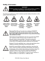
MH 4 Beam User Manual Professional Entertainment Technology © 2013-2014 Martin Professional. Information subject to change without notice. Martin Professional and all affiliated companies disclaim liability for any injury, damage, direct or indirect loss, consequential or economic loss or any other loss occasioned by the use of, inability to use or reliance on the information contained in this manual. The Martin logo, the RUSH by Martin logo, the RUSH by Martin name, the Martin name and all other trademarks in this document pertaining to services or products by Martin Professional or its affiliates and subsidiaries are trademarks owned or licensed by Martin Professional or its affiliates or subsidiaries. Martin Professional • Olof Palmes Allé 18 • 8200 Aarhus N • Denmark • www.martin.com Manual: Revision D Table of contents Safety information.............................................................................................................. 4 Introduction ........................................................................................................................ 9 Before using the product for the first time ...................................................................... 9 Physical installation ......................................................................................................... 10 Fastening the fixture to a flat surface ........................................................................... 10 Mounting the fixture on a truss .................................................................................... 10 Securing with a safety cable ........................................................................................ 11 AC power ......................................................................................................................... 12 Linking fixtures to power in a chain .............................................................................. 13 Fixture overview............................................................................................................... 13 DMX data link............................................................................................................... 14 Connecting the data link .............................................................................................. 15 Fixture setup .................................................................................................................... 15 Using the control panel ................................................................................................ 15 DMX function settings .................................................................................................. 16 Fixture settings ............................................................................................................ 16 Lamp settings .............................................................................................................. 17 Display settings ........................................................................................................... 18 Fixture tests ................................................................................................................. 20 Fixture information ....................................................................................................... 20 Special functions ......................................................................................................... 21 Effect home position (offset) adjustment ...................................................................... 22 Effects ............................................................................................................................. 23 Lamp control ................................................................................................................ 23 Pan and tilt................................................................................................................... 23 Dimming ...................................................................................................................... 23 Strobe effects .............................................................................................................. 24 Gobos .......................................................................................................................... 24 Prism ........................................................................................................................... 25 Color wheel .................................................................................................................. 25 Maintenance .................................................................................................................... 26 Changing the lamp....................................................................................................... 26 Cleaning ...................................................................................................................... 27 Changing the primary fuse........................................................................................... 28 Service and repairs ...................................................................................................... 28 DMX protocol ................................................................................................................... 30 Control menus ................................................................................................................. 35 Offset menu ..................................................................................................................... 38 Error messages ............................................................................................................... 39 Troubleshooting ............................................................................................................... 40 Specifications .................................................................................................................. 42 Safety information WARNING! Read the safety precautions in this manual before installing, powering, operating or servicing this product. The following symbols are used to identify important safety information on the product and in this manual: Warning! Warning! Warning! Warning! Safety hazard. Powerful light Refer to Hazardous Risk of severe emission. Risk manual before voltage. Risk injury or of eye injury. installing, of lethal or death. powering or severe electric servicing. shock. Warning! Hot surfaces and fire hazard. Warning! Risk Group 2 product according to EN 62471. Avoid looking directly into the beam and do not view the light output with optical instruments or any device that may concentrate the beam. This product is for professional use only. It is not for household use. It presents risks of severe injury or death due to fire hazards, electric shock and falls. It produces a powerful, concentrated beam of light that can create a fire hazard or a risk of eye injury if the safety precautions below are not followed. Respect all locally applicable laws, codes and regulations when installing, powering, operating or servicing the fixture. Read this manual before installing, powering or servicing the fixture, follow the safety precautions listed below and observe all warnings in this manual and printed on the fixture. Keep this manual for future use. If you have questions about how to operate the fixture safely, please contact your RUSH by Martin™ dealer or call the Martin™ 24-hour service hotline on +45 8740 0000, or in the USA on 1-888-tech-180. 4 RUSH MH 4 Beam User Manual For the latest user documentation and other information about this and all Martin™ products, please visit the Martin website at http://www.martin.com Protection from electric shock Do not expose the fixture to rain or moisture. Shut down power to the fixture before carrying out any installation or maintenance work and when the fixture is not in use. Ensure that the fixture is electrically connected to ground (earth). Use only a source of AC power that complies with local building and electrical codes and has both overload and ground-fault (earth-fault) protection. Socket outlets or external power switches used to supply the fixture with power must be located near the fixture and easily accessible so that the fixture can easily be disconnected from power. Disconnect the fixture from AC power before removing or installing any cover or part and when not in use. Replace defective fuses with ones of the specified type and rating only. Isolate the fixture from power immediately if the power plug or any seal, cover, cable, or other component is damaged, defective, deformed, wet or showing signs of overheating. Do not reapply power until repairs have been completed. Before using the fixture, check that all power distribution equipment and cables are in perfect condition and rated for the current requirements of all connected devices. Use only Neutrik PowerCon cable connectors to connect to power sockets. Do not connect devices to power in a chain that will exceed the electrical ratings of any cable or connector used in the chain. The supplied power input cable is rated 6 A and can safely supply only one fixture with mains power. Do not connect any device to the fixture’s MAINS OUT connector when using this cable. If you replace this cable and also use the replacement cable to supply only one fixture with mains power, the RUSH MH 4 Beam User Manual 5 replacement cable must also be rated 6 A minimum, have three conductors 18 AWG or 0.75 mm² minimum conductor size, have an outer cable diameter of 6 - 15 mm (0.2 - 0.6 in.) and be temperature-rated to suit the application. In the USA and Canada the cable must be UL listed, type SJT or equivalent. In the EU the cable must be type H05VV-F or equivalent. To connect fixtures to mains power in a chain, you must first obtain 12 AWG or 2.5 mm2 power input and throughput cables that are 16 A rated and temperature-rated to suit the application. In the USA and Canada the cables must be ULlisted, type SJT or equivalent. In the EU the cables must be type H05VV-F or equivalent. Suitable cables with Neutrik PowerCon connectors are available from Martin™ (see Accessories on page 44). If you use these cables, you can connect fixtures to power in a linked chain, MAINS OUT throughput socket to MAINS IN input socket, but do not link more than: • five (5) RUSH MH 4 fixtures in total at 100-120 V, or • ten (10) RUSH MH 4 fixtures in total at 200-240 V. The voltage and frequency at the MAINS OUT socket are the same as the voltage and frequency applied to the MAINS IN socket. Only connect devices to the MAINS OUT socket that accept this voltage and frequency. Protection from burns and fire Do not use the fixture to illuminate surfaces within 6.5 m (21.3 ft.) of the fixture. Do not operate the fixture if the ambient temperature (Ta) exceeds 40° C (104° F). The surface of the product casing can reach up to 90° C (176° F) during operation. Avoid contact by persons and materials. Allow the fixture to cool for at least 60 minutes before handling. Keep flammable materials well away from the fixture. Keep all combustible materials (e.g. fabric, wood, paper) at least 100 mm (4 in.) away from the fixture head. Ensure that there is free and unobstructed airflow around the fixture. Provide a minimum clearance of 100 mm (4 in.) around fans and air vents. Do not attempt to bypass thermostatic switches or fuses. 6 RUSH MH 4 Beam User Manual Do not stick filters, masks or other materials onto any optical component. Lamp safety Install only a lamp that is approved for use in the product. Prolonged exposure to an unshielded discharge lamp can cause eye and skin burns. Do not stare directly into the light output. Never look at an exposed lamp while it is lit. Do not operate the fixture with missing or damaged covers, shields, lenses, ultraviolet screens or any optical component. A hot discharge lamp is under pressure and can explode without warning. Allow the fixture to cool for at least 2 hours and protect yourself with safety glasses and gloves before handling a lamp. Replace the lamp immediately if it becomes visually deformed, damaged or in any way defective. Monitor hours of lamp use and lamp intensity and replace the lamp when it reaches the limit of its service life as specified in this manual or by the lamp manufacturer. If the quartz envelope of a discharge lamp is broken, the lamp releases a small quantity of mercury and other toxic gases. If a discharge lamp explodes in a confined area, evacuate the area and ventilate it thoroughly. Wear nitrite gloves when handling a broken discharge lamp. Treat broken or used discharge lamps as hazardous waste and send to a specialist for disposal. Protection from eye injury Do not look directly into the light beam. Do not point the beam in a direction where a person can look directly into it. Ensure that persons are not looking at the light beam when the product lights up suddenly. This can happen when power is applied, when the product receives a DMX signal, or when certain control menu items are selected. Do not look at the beam with magnifiers, telescopes, binoculars or similar optical instruments that may concentrate the light output. To minimize the risk of eye irritation or injury, disconnect the fixture from power at all times when the fixture is not in use, and provide well-lit conditions to reduce the pupil diameter of anyone working on or near the fixture. RUSH MH 4 Beam User Manual 7 Protection from injury Fasten the fixture securely to a fixed surface or structure when in use. The fixture is not portable when installed. Ensure that any supporting structure and/or hardware used can hold at least 10 times the weight of all the devices they support. If suspending from a rigging structure, fasten the fixture to a rigging clamp. Do not use safety cables as the primary means of support. If the fixture is installed in a location where it may cause injury or damage if it falls, install as directed in this manual a secondary attachment such as a safety cable that will hold the fixture if a primary attachment fails. The secondary attachment must be approved by an official body such as TÜV as a safety attachment for the weight that it secures, must comply with EN 60598-2-17 Section 17.6.6 and must be capable of bearing a static suspended load that is ten times the weight of the fixture and all installed accessories. Allow enough clearance around the head to ensure that it cannot collide with an object or another fixture when it moves. Check that all external covers and rigging hardware are securely fastened. Do not operate the fixture with missing or damaged covers, shields or any optical component. Block access below the work area and work from a stable platform whenever installing, servicing or moving the fixture. Do not lift or carry the fixture by its head. Always ensure that the fixture is supported by its base. In the event of an operating problem, stop using the fixture immediately and disconnect it from power. Never attempt to use a fixture that is obviously damaged. Do not modify the fixture or install other than genuine RUSH by Martin™ parts. Refer any service operation not described in this manual to a qualified technician. 8 RUSH MH 4 Beam User Manual Introduction The RUSH MH 4 Beam™ is a compact-beam moving head, equipped with an MSD Platinum 2R lamp in a state-of-the-art optical system. The device is extremely rugged, lightweight and compact, ideal for smaller venues. The fixture produces an intense and narrow beam for spectacular mid-air looks and effects. It houses a fixed gobo wheel and color wheel with a multitude of effects possible from a dimmer and strobe, 6-facet prism and focus. The fixture can be controlled using any DMX-compliant controller. The fixture is supplied with a 1.5 m (5 ft) power cable (local power plug not included) and two omega-type mounting brackets. Before using the product for the first time 1. Read ’Safety information’ on page 4 before installing, powering, operating or servicing the fixture. 2. Unpack and ensure that there is no transportation damage before using the fixture. Never attempt to operate a damaged fixture. 3. If the fixture is not going to be hard-wired to an AC mains power source, install a local power plug (not supplied) on the end of the supplied power cable. 4. Before operating, ensure that the voltage and frequency of the local power source match the mains power requirements of the fixture. 5. Check the Martin Professional website at www.martin.com for the most recent user documentation and technical information for the fixture. RUSH by Martin™ user manual revisions are identified by the revision letter at the bottom of the inside cover. Note that whenever AC mains power is applied to the fixture, it will reset all effects and functions to their home positions. The fixture head will move. This process usually takes around 20 seconds. RUSH MH 4 Beam User Manual 9 Physical installation Read ‘Safety information’ on page 4 before installing the fixture. The fixture is designed for indoor use only and must be used in a dry location with adequate ventilation. Ensure that none of the fixture’s ventilation slots are blocked and ensure that the product is fastened to a secure structure or surface. Fastening the fixture to a flat surface The fixture can be fastened to a hard, fixed, flat surface that is oriented at any angle. Ensure that the surface and all fasteners used can support at least 10 times the weight of all fixtures and equipment they will support. Fasten the fixture securely. Do not stand it on a surface or leave it where it can be moved or fall over. If you install the fixture in a location where it may cause injury or damage if it falls, secure it as directed below with a securely anchored safety cable that will hold the fixture if the primary fastening method fails. Mounting the fixture on a truss The fixture can be clamped to a truss or similar rigging structure in any orientation. When installing the fixture hanging vertically down, you can use an open-type clamp such as a G-clamp. When installing in any other orientation, you must use a half-coupler clamp (see illustration on right) that completely encircles the truss chord. To clamp the fixture to a truss: 1. Check that the rigging structure can support at least 10 times the weight of all fixtures and equipment to be installed on it. 2. Block access under the work area. 3. The fixture is supplied with two omega-type brackets to which rigging clamps can be attached. Bolt a rigging clamp securely to each bracket. The bolts used must be M12, grade 8.8 steel minimum, and fastened with self-locking nuts. 4. Fasten the omega brackets to the base of the fixture using the brackets’ quarter-turn fasteners. Turn quarterturn fasteners a full 90° to lock them (see illustration on right). 10 RUSH MH 4 Beam User Manual 5. Working from a stable platform, hang the fixture on the truss and fasten the rigging clamps onto the truss. 6. Secure the fixture with a safety cable as directed below. 7. Check that the head will not collide with other fixtures or objects. Securing with a safety cable Secure the fixture with a safety cable (or other secondary attachment) that is approved for the weight of the fixture so that the safety cable will hold the fixture if a primary attachment fails. Loop the safety cable through the cutout in the fixture’s baseplate (arrowed in illustration on right) and around a secure anchoring point. RUSH by Martin™ can supply suitable safety cables and rigging clamps (see Accessories on page 44). RUSH MH 4 Beam User Manual 11 AC power Read ‘Safety information’ on page 4 before connecting the fixture to AC mains power. Warning! The mains power input cable supplied with the fixture is rated 6 A and can supply only one fixture with mains power. Do not connect any device to the fixture’s MAINS OUT power throughput socket when using this input cable. If you want to connect other fixtures to the MAINS OUT socket, see ‘Linking fixtures to power in a chain’ on page 13. For protection from electric shock, the fixture must be grounded (earthed). The power distribution circuit must be equipped with a fuse or circuit breaker and ground-fault (earth-fault) protection. Socket outlets or external power switches used to supply the fixture with power must be located near the fixture and easily accessible so that the fixtures can easily be disconnected from power. Do not insert or remove live Neutrik PowerCon connectors to apply or cut power, as this may cause arcing at the terminals that will damage the connectors. Do not use an external dimming system to supply power to the fixture, as this may cause damage to the fixture that is not covered by the product warranty. The fixture can be hard-wired to a building electrical installation if you want to install it permanently, or a power plug (not supplied) that is suitable for the local power outlets can be installed on the power cable. If you install a power plug on the power cable, follow the plug manufacturer’s instructions and connect the wires in the power cable as shown in this table: Earth, Ground or Neutral or N Live or L US system Green White Black EU system Yellow/green Blue Brown The fixture has an auto-ranging power supply that accepts AC mains power at 100-240 V at 50/60 Hz. Do not apply AC mains power at any other voltage or frequency to the fixture. 12 RUSH MH 4 Beam User Manual Linking fixtures to power in a chain If you obtain a 12 AWG or 2.5 mm2 power input cable and 12 AWG or 2.5 mm2 throughput cables from Martin™ (see ‘Accessories’ on page 44), you can relay mains power from one fixture to another by connecting fixtures to power in a linked daisy-chain, MAINS OUT throughput socket to MAINS IN input socket. Using 12 AWG or 2.5mm2 cables from Martin™, you can link: • Maximum five (5) RUSH MH 4 fixtures to power in a chain at 100-120 V, or • Maximum ten (10) RUSH MH 4 fixtures to power in a chain at 200-240 V. Fixture overview 1 - LEDs The fixture has four LEDs on the front of the base: two are reserved for future use; the other two are marked as follows: Power Power on DMX Valid DMX signal present 2 – Display 3 – Buttons MENU • Activate the menu mode functions, or • Return to the previous level of the menu structure, or • Press and hold to exit the menus DOWN Go down a menu branch UP Go up a menu branch ENTER Confirm the selected menu item 4 - DMX XLR input/output sockets: RUSH MH 4 Beam User Manual 13 5 – AC mains power IN 6 – AC mains power OUT 7 – Primary (mains power) fuse F1 DMX data link A DMX 512 control data link is required in order to control the fixture via DMX. The fixture has 3-pin and 5-pin XLR connectors for DMX data input and output (throughput). The number of daisy-chained fixtures is limited by the number of DMX channels required by the fixtures in relation to the maximum 512 channels available in one DMX universe. Note that if independent control of a fixture is required, it must have its own DMX channels. Fixtures that are required to behave identically can share the same DMX address and channels. To add more fixtures or groups of fixtures when the above limit is reached, add a DMX universe and another daisy-chained link. Note that if a fixture loses its DMX signal it will maintain its current effect until powered off or reset. 14 RUSH MH 4 Beam User Manual Tips for reliable data transmission Use shielded twisted-pair cable designed for RS-485 devices: standard microphone cable cannot transmit control data reliably over long runs. 24 AWG cable is suitable for runs up to 300 meters (1000 ft.). Heavier gauge cable and/or an amplifier is recommended for longer runs. The pin-out on all connectors is pin 1 = shield, pin 2 = cold (-), and pin 3 = hot (+). Pins 4 and 5 in the 5-pin XLR connectors are not used in the fixture but are available for possible additional data signals as required by the DMX512-A standard. Standard pin-out is pin 4 = data 2 cold (-) and pin 5 = data 2 hot (+). To split the link into branches, use a splitter such as the Martin DMX 5.3 Splitter™ or Martin RDM 5.5 Splitter™. Terminate the link by installing a termination plug in the output socket of the last fixture. The termination plug, which is a male XLR plug with a 120 Ohm, 0.25-Watt resistor soldered between pins 2 and 3, “soaks up” the control signal so it does not reflect and cause interference. If a splitter is used, terminate each branch of the link. Connecting the data link To connect the fixture to data: 1. Connect the DMX data output from the controller to the first fixture’s male XLR DMX input connector. 2. Connect the first fixture’s DMX output to the DMX input of the next fixture and continue connecting fixtures output to input. Terminate the last fixture on the link with a DMX termination plug. Fixture setup This section explains the options available to change the fixture’s settings. Settings are made using the menus available in the control panel and are retained when the fixture is powered off. A complete map of the control menu structure and brief explanations of their purposes can be found in ‘Control menus’ on page 35. Using the control panel • • • • • • To access the control menus in the control panel, press the MENU button. Navigate the menu structure using the ENTER, DOWN and UP buttons. Scroll between menu items using the DOWN and UP buttons. Select any required menu option using the ENTER button. To return to the previous level in the menu structure without making a change, press the MENU button. To exit the menus, press and hold the MENU button. RUSH MH 4 Beam User Manual 15 DMX function settings DMX function settings include the DMX address and DMX mode. DMX addressing The fixture can be controlled using signals sent by a DMX controller over 13 DMX channels. The DMX address, also known as the start channel, is the first channel used to receive instructions from the DMX controller. Each DMXcontrolled fixture must have a DMX address set. If a fixture has its DMX address set to 1 and you want to use all 15 channels, then the next fixture can have a DMX address of 16, the next 31, then 46, and so on until the 512 channels in one DMX universe have all been allocated. For independent control, each fixture must be assigned its own DMX channels. Two fixtures of the same type may share the same address, if identical behavior is desired. Address sharing can be useful for diagnostic purposes and symmetric control, particularly when combined with the inverse pan and tilt options. To set the fixture’s DMX address: 1. Select DMX FUNCTIONS in the control panel and press ENTER. 2. Use the UP and DOWN buttons to select DMX ADDRESS and press ENTER. The fixture’s current DMX address will blink in the display. 3. Use the UP and DOWN buttons to select a new address (1 to 512). 4. Once the address has been selected, press ENTER to set it (or to return to the previous menu level without making a change, press MENU). Viewing DMX values received DMX FUNCTIONS View DMX value lets you see the DMX values the fixture is receiving on each of the DMX channels. Fixture settings Pan and/or tilt inversion The FIXTURE SETTINGS PAN INVERSE and TILT INVERSE menus let you remap the fixture so that the direction of pan and/or tilt are reversed. These settings are useful for symmetrical effects with multiple fixtures, or when coordinating the movement of fixtures that are floor-mounted and rigged upside down. 16 RUSH MH 4 Beam User Manual Pan/tilt feedback If you enable pant and tilt feedback in the FIXTURE SETTINGS P/T FEEDBACK menu, the fixture will correct its pan and tilt positions if it detects a position error. Blackout during effect changes or movement You can set the fixture to deploy the shutter to black out light output during pan and tilt movement, gobo changes and/or color changes. Blackouts are disabled by default. Lamp settings Lamp on/off To manually power the lamp on or off: 1. Select LAMP SETTINGS and press ENTER to confirm. 2. Use the DOWN and UP buttons to scroll to ON/OFF and press ENTER to confirm. 3. Use the DOWN and UP buttons to select ON or OFF. 4. Press ENTER to confirm and power the lamp on or off (or to return to the previous level of the menu structure without making a change, press MENU). State/power on To set the lamp to power on automatically when the fixture is powered on: 1. Select LAMP SETTINGS and press ENTER to confirm. 2. Use the DOWN and UP buttons to select STATE/POWER ON and press ENTER to confirm. 3. Use the DOWN and UP buttons to select ON or OFF. 4. Press ENTER to confirm (or to return to the previous menu level without making a change, press MENU). DMX lamp control The lamp can be controlled remotely by DMX. The following options are available: • OFF VIA DMX allows the lamp to be powered off by sending a DMX command. • ON IF DMX ON sets the lamp to power on automatically as soon as a DMX signal is present. RUSH MH 4 Beam User Manual 17 • OFF IF DMX OFF sets the lamp to power off automatically as soon as a DMX signal is not present Ignition delay If a large number of fixtures power their lamps on at the same time, voltage drops can result. To spread the load across multiple fixtures, an ignition delay of 0 to 255 seconds can be set, so that there is a delay between power on and lamp on. 1. Select LAMP SETTINGS and press ENTER to confirm. 2. Use the DOWN and UP buttons to select IGNITION DELAY and press ENTER to confirm. 3. Use the DOWN and UP buttons to specify a delay duration in seconds. 4. Press ENTER to confirm (or to return to the previous menu level without making a change, press MENU). Low power delay In a low-power delay, when a lamp off command is sent the lamp runs at half power for a period before powering completely off: 1. Select LAMP SETTINGS and press ENTER to confirm. 2. Use the DOWN and UP buttons to select LOW POWER DELAY and press ENTER to confirm. 3. Use the DOWN and UP buttons to specify a duration. 4. Press ENTER to confirm (or to return to the previous menu level without making a change, press MENU). Display settings Invert display Inverting the display is useful if the fixture is hung from a truss or from elevation. To invert the display: 1. Select DISPLAY SETTINGS and press ENTER to confirm. 2. Use the DOWN and UP buttons to select DISPLAY INVERSE and press ENTER to confirm. 3. Use the DOWN and UP buttons to select the YES (invert). 4. Press ENTER to confirm (or to return to the previous menu level without making a change, press MENU). Automatically turn off display backlight The display backlighting remains on permanently by default when power is applied to the fixture. If you prefer, you can enable Sleep mode, where the 18 RUSH MH 4 Beam User Manual backlighting goes off automatically when the buttons and menus have not been used for a short period: 1. Select DISPLAY SETTINGS and press ENTER to confirm. 2. Use the DOWN and UP buttons to select BACKLIGHT AUTO OFF and press ENTER to confirm. 3. Use the DOWN and UP buttons to select YES to enable automatic dimming. 4. Press ENTER to confirm (or to return to the previous menu level without making a change, press MENU). Adjust backlight intensity The brightness of the control panel display can be adjusted: 1. Select DISPLAY SETTINGS and press ENTER to confirm. 2. Use the DOWN and UP buttons to select BACKLIGHT INTENSITY and press ENTER to confirm. 3. Use the DOWN and UP buttons to set a level from 1 to 10. 4. Press ENTER to confirm (or to return to the previous menu level without making a change, press MENU). Display panel contrast To adjust the contrast of the control panel display to get the clearest readout: 1. Select DISPLAY SETTINGS and press ENTER to confirm. 2. Use the DOWN and UP buttons to adjust the intensity ratio from 1 (dark) to 30 (bright) and press ENTER to confirm. 3. Press MENU to return to the previous menu level or let the unit idle one minute to exit menu mode. Temperature Celsius/Fahrenheit To set temperatures to display in Celsius or Fahrenheit 1. Select TEMPERATURE UNIT and press ENTER to confirm. 2. Use DOWN and UP buttons to select ° C or ° F and press ENTER to store. 3. Press MENU to return to the previous menu level or let the unit idle one minute to exit menu mode. Display warnings To enable or disable error messages in the display if the fixture detects an error: 1. Select DISPLAY WARNING and press ENTER to confirm. RUSH MH 4 Beam User Manual 19 2. Use the DOWN and UP buttons to select YES or NO and press ENTER to confirm. 3. Press MENU to return to the previous menu level or let the unit idle one minute to exit menu mode. Fixture tests The fixture can carry out an automatic test of all functions, or individual functions can be tested manually. Auto test To perform a complete test of all of the effects: 1. Select FIXTURE TEST and press ENTER to confirm. 2. Use the DOWN and UP buttons to select AUTO TEST and press ENTER to confirm. The fixture will run an automatic test sequence of all the effects. Manual test (manual control of individual effects) To test individual effects: 1. Select FIXTURE TEST and press ENTER to confirm. 2. Use the DOWN and UP buttons to select MANUAL TEST and press ENTER to confirm. 3. Select the function you want to test and press ENTER to confirm. You can now test that function. 4. To return to the previous menu level, press MENU. Fixture information Fixture operating hours counter (non-resettable) To see how many hours the fixture has been used since manufacture: 1. Select FIXTURE INFORMATION and press ENTER to confirm. 2. Use the DOWN and UP buttons to select FIXTURE USE TIME and press ENTER to confirm. The number of hours will be shown. Lamp operating hours counter (resettable) This counter can be reset. It can be used to monitor the number of lamp operating hours and help you decide when a lamp change is required. 1. Select FIXTURE INFORMATION and press ENTER to confirm. 20 RUSH MH 4 Beam User Manual 2. Use the DOWN and UP buttons to select LAMP ON TIME and press ENTER to confirm. The fixture will display the number of hours the lamp has been on since the counter was last reset. 3. Use the DOWN and UP buttons to select EXIT to leave the lamp hours menu or RESET TIME to reset the lamp hours counter to zero. Press ENTER to confirm. Firmware version To see which software version is installed in the fixture: 1. Select FIXTURE INFORMATION and press ENTER to confirm. 2. Use the DOWN and UP buttons to select FIRMWARE VERSION and press ENTER to confirm. The firmware version will be shown. Reset functions or effects Individual effects (pan, tilt color, gobos, focus, prism) or all the effects can be manually reset to their home positions: 1. Select RESET FUNCTIONS and press ENTER to confirm. 2. Use the DOWN and UP buttons to select the function or effect that is to be reset. Press the ENTER button. 3. Use the DOWN and UP buttons to select YES and press ENTER to confirm (or to return to the previous menu level without making a change, press MENU). Special functions Fixture maintenance You can schedule fixture maintenance by setting an interval in hours until the next service must be carried out. You can then view the number of hours remaining until this interval has been reached: 1. Select FIXTURE MAINTENANCE and press ENTER to confirm. 2. Use the DOWN and UP buttons to select INTERVAL or REMAIN TIME. Interval 1. Select INTERVAL and press ENTER to confirm. The interval time will show on the display. 2. Press MENU button to exit. Remain Time 1. Select Remain Time and press ENTER to confirm. The remaining time will show on the display. RUSH MH 4 Beam User Manual 21 2. Press ENTER, then use the DOWN and UP buttons to select EXIT or RESET TIME. EXIT returns to the previous menu without changing the remaining time. RESET TIME restarts the timer countdown at the number of hours defined in INTERVAL. 3. Press ENTER to confirm or press MENU to exit. Factory settings The fixture’s factory default settings can be restored using FACTORY SETTINGS. Effect home position (offset) adjustment The fixture’s effects (pan, tilt, shutter, color, gobo, prism, rotating prism and focus) can lose their home position if the fixture is exposed to shocks, for example. To adjust the effect’s home position: 1. In the menu structure, press ENTER and hold for at least 3 seconds to enter the OFFSET MENU. 2. Use the DOWN and UP buttons to choose the effect that needs to be adjusted. Press ENTER to select it. 3. The effect’s currently indexed home position will flash in the display. Use the DOWN and UP buttons to adjust it. 4. Once the correct position has been reached, press ENTER to set this (or to return to the previous menu level without making a change, press MENU). 22 RUSH MH 4 Beam User Manual Effects This section describes DMX-controllable effects that require particular explanation. See DMX protocol on page 30 for a full list of the DMX channels and values required to control the different effects. Lamp control For maximum lamp operating life: • Avoid powering the lamp off until it has warmed up for at least 5 minutes. • Before shutting down power completely, douse the lamp but leave power applied for a few minutes so that cooling fans can prevent any momentary lamp temperature increase caused by heat from surrounding components. The fixture can be set to automatically turn the lamp on or off depending on whether or not a DMX signal is present. The fixture can also be set to respond to or ignore lamp off commands sent via DMX. An ignition delay of 0 to 255 seconds can be set, so that there is a delay between power on and lamp on. A low-power delay of 0 to 255 seconds can be set, so that when a lamp off command is sent the lamp runs at half power for a user-defined period before shutting down. For more information, see ‘Lamp settings’ on page 17. Pan and tilt The fixture’s moving head can be panned through 540° and tilted through 270° using coarse or fine control channels. The fixture can be set to automatically blackout during pan and tilt movement. The fixture incorporates pan and tilt feedback, so that if a pan or tilt position error is detected, the shutter closes and the fixture resets to the correct position. This can be enabled or disabled as required (see ‘Control menus’ on page 35). Dimming Full range mechanical dimming is provided. RUSH MH 4 Beam User Manual 23 Strobe effects A range of variable strobe and pulse effects are available, with variable speed and random effects. Gobos The fixture contains a rotating wheel with 17 fixed gobos plus open (white): Any gobo can be projected, with split gobos also possible, or the wheel can be rotated clockwise or counter-clockwise at variable speeds. The sharpness of gobo projections can be adjusted using the Focus adjustment DMX channel. 24 RUSH MH 4 Beam User Manual Prism The fixture incorporates a 6-facet prism that can be inserted into the beam to provide split effects. The prism can be set to an indexed position or rotated clockwise or counter-clockwise. Color wheel The fixture incorporates a single color wheel with 14 color filters plus open. The colors can be individually selected, split colors are available, and the wheel can be rotated at varying speeds clockwise and counter-clockwise. The filters installed as standard in the color wheel are as follows: Open Slot 1 Slot 2 Slot 3 Slot 4 Slot 5 Slot 6 Slot 7 Red Amber Blue Green Light green Lavender Pink Slot 8 Slot 9 Slot 10 Slot 11 Slot 12 Slot 13 Slot 14 Light yellow Magenta Deep blue Yellow CTO CTB Violet RUSH MH 4 Beam User Manual 25 Maintenance Read ‘Safety Information’ on page 5 before servicing the fixture. Refer any service operation not described in this user manual to a qualified service technician. Disconnect mains power before cleaning or servicing the fixture. Service the fixtures in an area where there is no risk of injury from falling parts, tools or other materials. Changing the lamp Read ‘Lamp safety’ on page 7 before servicing the lamp. To avoid the risk of a discharge lamp exploding in the fixture, always replace the lamp before its expected lifespan has been exceeded. The lamp must be perfectly clean. Never touch the lamp with bare hands. If this happens, clean the lamp with an alcohol wipe and dry it with a lint-free cloth. To replace the lamp: 1. If the fixture has been in use, power the lamp off but leave the fixture powered on for at least 10 minutes so that the cooling fans cool the lamp. Disconnect the fixture from power and allow it to cool for 60 minutes. 2. Remove the fixture head covers using a Phillips screwdriver. 3. Remove the fan at the rear of the head. 4. Lift the lamp out of its recess. 5. Disconnect the lamp and connect the replacement lamp. Use an approved lamp only. 26 RUSH MH 4 Beam User Manual 6. Place the new lamp into the lamp recess. 7. The lamp can be adjusted using a slotted (flat head) screwdriver. Ensure that the lamp is located in the center of the reflector for the best projection. 8. Reinstall and fasten the fan. 9. Reinstall and fasten the head covers. 10. Remember to reset the lamp hours counter using the control panel. Cleaning Excessive dust, smoke fluid, and particle buildup degrades performance, causes overheating and will damage the fixture. Damage caused by inadequate cleaning or maintenance is not covered by the product warranty. The cleaning of external optical lenses must be carried out periodically to optimize light output. Cleaning schedules for lighting fixtures vary greatly depending on the operating environment. It is therefore impossible to specify precise cleaning intervals for the fixture. Environmental factors that may result in a need for frequent cleaning include: • Use of smoke or fog machines. • High airflow rates (near air conditioning vents, for example). • Presence of cigarette smoke. • Airborne dust (from stage effects, building structures and fittings or the natural environment at outdoor events, for example). RUSH MH 4 Beam User Manual 27 If one or more of these factors is present, inspect fixtures within their first 100 hours of operation to see whether cleaning is necessary. Check again at frequent intervals. This procedure will allow you to assess cleaning requirements in your particular situation. If in doubt, consult your RUSH by Martin dealer about a suitable maintenance schedule. Use gentle pressure only when cleaning, and work in a clean, well-lit area. Do not use any product that contains solvents or abrasives, as these can cause surface damage. To clean the fixture: 1. Disconnect the fixture from power and allow it to cool for at least 60 minutes. 2. Vacuum or gently blow away dust and loose particles from the outside of the fixture and the air vents at the back and sides of the head and in the base with low-pressure compressed air. 3. Clean optical components by wiping gently with a soft, clean lint-free cloth moistened with a weak detergent solution. Do not rub the surface hard: lift particles off with a soft repeated press. Dry with a soft, clean, lint-free cloth or low-pressure compressed air. Remove stuck particles with an unscented tissue or cotton swab moistened with glass cleaner or distilled water. 4. Check that the fixture is dry before reapplying power. Changing the primary fuse If the fixture is completely dead, the fixture’s primary fuse F1 may have blown and it may be necessary to install a new fuse. This fuse is located in a fuseholder next to the Mains OUT socket on the connections panel. See 7 in ‘Fixture overview’ on page 13. To change the fuse: 1. Disconnect the fixture from power and allow it to cool for at least 60 minutes. 2. Use a large flat-bladed screwdriver to open the fuseholder. 3. Replace the fuse with one of the same type and rating only. 4. Reinstall the fuseholder cap before reapplying power. Service and repairs There are no user serviceable parts inside the fixture. Do not open the housing. Do not try to repair the fixture by yourself as this may result in damage or malfunction, and it may potentially void your product warranty. The fixture 28 RUSH MH 4 Beam User Manual must be serviced or repaired by an authorized RUSH by Martin™ service technician only. Installation, on-site service and maintenance can be provided worldwide by the Martin Professional Global Service organization and its approved agents, giving owners access to Martin’s expertise and product knowledge in a partnership that will ensure the highest level of performance throughout the product’s lifetime. Please contact your RUSH by Martin™ supplier for details. RUSH MH 4 Beam User Manual 29 DMX protocol Channel Value Function Fade type Default 1 0-255 Dimming coarse 0100% Fade 0 2 0-255 Dimming fine Fade 0 Shutter Closed Open Shutter strobe effect, slow fast Fast close, slow open Slow close, fast open Pulse open and close Shutter strobe effect, random strobe Open Snap 12 0-7 8-15 16-131 132-167 168-203 204-239 240-247 248-255 Color wheel: continuous scrolling Open Open Red Red Red Amber Amber Amber Blue Blue Blue Green Green Green Light green Light green Light green Lavender Lavender Lavender Pink Pink Pink Light yellow Light yellow Light yellow Magenta Magenta Magenta Deep blue Deep blue Deep blue Yellow Yellow Snap 0 0 1-10 11 12-21 22 23-32 33 34-43 44 45-54 55 56-65 66 67-76 77 78-87 88 89-98 99 100-109 110 111-120 121 3 4 30 RUSH MH 4 Beam User Manual Channel Value 122-131 132 133-142 143 144-153 154 155-159 160 161-162 163-164 165-166 167-167 169-170 171-172 173-174 175-176 177-178 179-180 181-182 183-184 185-186 187-188 189-192 193-214 215-221 222-243 244-247 248-251 252-255 5 0 1-8 9 10-17 18 19-26 27 28-35 Function Fade type Default Snap 0 Yellow CTO CTO CTO CTB CTB CTB Violet Violet Violet Open Open Color wheel: stepped scrolling Red Amber Blue Green Light green Lavender Pink Light yellow Magenta Deep blue Yellow CTO CTB Violet Open Color wheel: continuous rotation Clockwise rotation fast slow Stop (wheel stops at current position) Counter-clockwise rotation slow fast Color wheel: random slots Random color, fast Random color, medium Random color, slow Gobo wheel: continuous scrolling Open Open Gobo 1 Gobo 1 Gobo 1 Gobo 2 Gobo 2 Gobo 2 Gobo 3 Gobo 3 Gobo 3 Gobo 4 RUSH MH 4 Beam User Manual 31 Channel Value 36 37-44 45 46-53 54 55-62 63 64-71 72 73-80 81 82-89 90 91-98 99 100-107 108 109-116 117 118-125 126 127-134 135 136-143 144 145-152 153 154-156 157-158 159-160 161-162 163-164 165-166 167-168 169-170 171-172 173-174 175-176 177-178 179-180 32 Function Gobo 4 Gobo 4 Gobo 5 Gobo 5 Gobo 5 Gobo 6 Gobo 6 Gobo 6 Gobo 7 Gobo 7 Gobo 7 Gobo 8 Gobo 8 Gobo 8 Gobo 9 Gobo 9 Gobo 9 Gobo 10 Gobo 10 Gobo 10 Gobo 11 Gobo 11 Gobo 11 Gobo 12 Gobo 12 Gobo 12 Gobo 13 Gobo 13 Gobo 13 Gobo 14 Gobo 14 Gobo 14 Gobo 15 Gobo 15 Gobo 15 Gobo 16 Gobo 16 Gobo 16 Gobo 17 Gobo 17 Gobo 17 Open Gobo wheel: stepped scrolling Gobo 1 Gobo 2 Gobo 3 Gobo 4 Gobo 5 Gobo 6 Gobo 7 Gobo 8 Gobo 9 Gobo 10 Gobo 11 Gobo 12 RUSH MH 4 Beam User Manual Fade type Default Channel Value 181-182 183-184 185-186 187-188 189-190 191-192 193-214 215-221 222-243 244-247 248-251 252-255 Function Fade type Default Gobo 13 Gobo 14 Gobo 15 Gobo 16 Gobo 17 Open Gobo wheel: continuous rotation Clockwise rotation fast slow Stop (wheel stops at current position) CCW rotation slow fast Gobo wheel: random gobos Random gobo, fast Random gobo, medium Random gobo, slow 6 Snap Prism 0-10 Open 11-138 Prism indexing (control on next channel) 139-255 Prism rotation (control on next channel) 7 Prism Indexing control Indexed position (128 = prism indexed at 0°) Prism Rotation control No rotation (prism indexed at 0°) 0-2 3-126 Rotation CW fast CW Slow 127-129 No rotation (prism stops at current position) 130-253 Rotation CCW Slow CCW Fast 254-255 No rotation (prism indexed at 45°) 0 Fade 128 0-255 8 0-255 Focus Infinity Near Fade 128 9 0-255 Pan coarse 0° 540° Fade 128 10 0-255 Pan fine Fade 0 11 0-255 Tilt coarse 0° 270° Fade 128 12 0-255 Tilt fine Fade 0 Fixture control No function (disables calibration) Reset fixture Reset dimmer/shutter Snap 0 0-9 10-14 15-19 13 RUSH MH 4 Beam User Manual 33 Channel Value Function Reset color Reset gobos Reset pan and tilt Reset focus Lamp on Lamp off No function Enable calibration No function Pan & tilt speed = Normal Pan & tilt speed = Fast (default) Pan & tilt speed = Slow Effect shortcuts = On (default) Effect shortcuts = Off No function Auto-blackout = On Auto-blackout = Off (default) Illuminate control panel display Turn off control panel display No function Store dimmer calibration Store gobo wheel calibration Store focus calibration Store color wheel calibration Store prism calibration Store pan calibration Store tilt calibration Reset all calibration values to factory defaults 250-255 No function 20-24 25-29 30-34 35-39 40-44 45-49 50-54 55-59 60-79 80-84 85-89 90-94 95-99 100-104 105-144 145-149 150-154 155-159 160-164 165-209 210-214 215-219 220-224 225-229 230-234 235-239 240-244 245-249 34 RUSH MH 4 Beam User Manual Fade type Default Control menus To access the control menus, press the MENU button. Use the UP and DOWN buttons to navigate the menus. Select any required menu option using the ENTER button. For more information, see ‘Using the control panel’ on page 15. Default fixture settings are shown in bold. Menu Sub-menu DMX Functions DMX Address Setting/ value 1-512 DMX Channel Mode View DMX Value Fixture setting Pan Inverse Tilt Inverse P/T Feedback No Yes No Yes No Yes Bl.O. P/T Moving Bl.O. Color Change Bl.O. Gobo Change No Yes No Yes No Yes Explanation Set fixture‘s DMX address Reserved for future use View DMX values received Invert pan movement (map left to right) Invert tilt movement (map up to down) No pan or tilt position error correction If a pan or tilt position error is detected, the fixture corrects pan/tilt position Blackout during pan or tilt movement Blackout during color change Blackout during gobo change RUSH MH 4 Beam User Manual 35 Lamp Setting On/Off State/Power On Off via DMX On if DMX On Off if DMX Off Display settings No Yes No Yes No Yes Ignition Delay 0-255S Low Power Delay 0-255S Display inverse No Yes No Yes Backlight Auto Off Backlight Intensity 1-10 Contrast 1-30 Temperature Unit °C °F No Yes Display Warning Fixture Test Off On Off On Auto Test Manual Test 36 RUSH MH 4 Beam User Manual Manually power lamp on or off Lamp powers on automatically when fixture is powered on Lamp can be powered off via DMX Lamp powers on if DMX signal received Lamp powers off if DMX signal not received Delay lamp ignition (0 to 255 seconds). Half-power period before powering lamp off completely (0 to 255 seconds) Invert control panel display Automatically turn off display panel backlight when not in use. Set display panel backlight intensity Set display panel contrast Temperature display Celsius/Fahrenheit Show service warnings in display panel Automatic test of all functions Manual test of each function Fixture Information Fixture Use Time Lamp On Time Total operating hours since manufacture Exit Reset Time Firmware Version Reset Functions Pan/Tilt Shutter/Dimmer Color Gobo Focus All Special Functions Fixture Maintenance No Yes No Yes No Yes No Yes No Yes No Yes Interval Remain time Factory Settings No Yes RUSH MH 4 Beam User Manual Reset lamp hour use counter Currently installed firmware version Reset pan and tilt Reset shutter/dimmer Reset color wheel Reset gobo wheel Reset focus Reset all effects Set new maintenance countdown timer period View maintenance countdown timer Return fixture to factory default settings 37 Offset menu The offset menu is used to adjust the home position of the various effects. To access the Offset menu, press the MENU button to enter the menu structure and then press and hold ENTER for three seconds. Menu Sub-menu Offset Menu Pan -128127 Pan offset Tilt -128127 Tilt offset Shutter 0255 Explanation Shutter offset Color -128127 Color offset Gobo -128127 Gobo offset Prism 0255 Prism offset R-Prism Focus 38 Setting -128127 0255 Rotating prism offset Focus offset RUSH MH 4 Beam User Manual Error messages Error: Appears when: Lamp Startup Fail No lamp detected or wiring fault. Temperature Sense Error Temperature sensor on the PCB is damaged. Contact your RUSH by Martin authorized distributor for assistance. Lamp Too Hot Low Power Temperature higher than 105º C detected. The fixture runs at a low power level. Lamp Too Hot Power Off Temperature higher than 110° C detected. Check that ambient temperature does not exceed 40° C. Check that fixture is adequately ventilated. The fans or temperature sensor might be damaged. Contact your RUSH by Martin authorized distributor for assistance. Maintenance Fixture Service countdown timer has reached zero. Service the fixture, then reset the countdown countdown timer in the control menu. Lamp On Over 2000 Hour The lamp has had more than 2000 hours of use. Change the lamp as directed in this manual. Continuing to use the lamp increases the risk of a lamp explosion. Memory Initial Fail Damaged memory IC. Contact your RUSH by Martin authorized distributor for assistance. CPU-B Error CPU-C Error CPU-D Error CPU, PCB or fixture wiring is damaged. Contact your RUSH by Martin authorized distributor for assistance. Pan Reset Error Pan Encode Error Tilt Reset Error Tilt Encode Error Shutter Reset Fail Dimmer Reset Fail Color Reset Fail Gobo Reset Fail Focus Reset Fail These can appear when powering on or resetting the fixture and can indicate damage to sensors or components. Contact your RUSH by Martin authorized distributor for assistance. RUSH MH 4 Beam User Manual 39 Troubleshooting This section describes a few common problems that may occur during operation and provides some suggestions for easy troubleshooting: Symptom Potential cause Remedies No light from fixture, or fans not working. Power supply issue, such Check that mains supply is as blown fuse, faulty connected and supplying connector or damaged power to the fixture. cable. Check that fixture’s Power indicator LED is lit. Check all power connections and cables. Replace fixture’s primary fuse. One of the control channels is unresponsive or only responds intermittently. Damaged step motor or cable connection between the head and body. Contact your RUSH by Martin™ authorized distributor for assistance. Lamp cuts out intermittently Incorrect mains voltage or the internal temperature is too high. Check mains voltage. Fixture does not respond to DMX control. Incorrect DMX addressing. Ensure that fixture’s DMX address matches address set on DMX control device. Fault on DMX link due to damaged connector or cable, or potential interference from proximity to a highvoltage installation. Fan may need replacing. Contact your RUSH by Martin™ authorized distributor for assistance. Check that fixture’s DMX indicator LED is on, and if not, check all DMX cables and connections. Check that DMX link is terminated. Check that all devices on 40 RUSH MH 4 Beam User Manual Symptom Potential cause Remedies DMX link use standard DMX polarity. Attempt to control the fixture with another DMX control device. Move or shield link if it is very close to an unshielded high-voltage installation. RUSH MH 4 Beam User Manual 41 Specifications Physical Weight ................................................................................14 kg (30.9 lbs.) Dimensions (W x H x D)...........319 x 256 x 481 mm (12.6 x 10.1 x 18.9 in.) Lamp Approved lamp .................................................... Philips MSD Platinum 2R Color temperature ............................................................................ 9000 K CRI (Color rendering index) .................................................................... 75 Average lifetime ......................................................................... 2000 hours Dynamic Effects Color wheel........... 14 colors plus open, continuous and stepped scrolling, ....................................................rotation with variable direction and speed Static gobo wheel . 17 gobos plus open, continuous and stepped scrolling, ....................................................rotation with variable direction and speed Shutter ................. Strobe effects, pulse effects, instant open and blackout Prism ....... 6-facet, indexing and rotation with variable direction and speed Focus ............................................................................................Motorized Dimmer ......................................................... 0 - 100% continuous dimming Pan ...................................................................................................... 540° Tilt ......................................................................................................... 270° 42 RUSH MH 4 Beam User Manual Control and Programming Control system .....................................................................................DMX DMX channels ..........................................................................................13 Setting and addressing.................... Control panel with backlit LCD display DMX compliance ....................................................... USITT DMX512/1990 16-bit control .....................................................................Dimming, pan, tilt Pan and tilt speed.............. Adjustable via onboard control panel and DMX Position correction system ........................................................ Pan and tilt Optics Beam angle .............................................................................................. 3° Construction Color .................................................................................................... Black Housing .................................... High-impact flame-retardant thermoplastic Protection rating .................................................................................. IP 20 Installation Mounting points .................... Four quarter-turn bracket mounting points Minimum distance from illuminated surfaces ....................... 6.5 m (21.3 ft.) Location ............. Indoor use only, must be fastened to surface or structure Orientation ............................................................................................. Any Connections AC power in/out .................................................................. Neutrik PowerCon DMX data in/out ................................................... 3-pin & 5-pin locking XLR Electrical AC power .......................................................100-240 V nominal, 50/60 Hz Fuse.................................................................................................... T6.3A Power supply unit .............................. Auto-ranging electronic switch-mode Typical power and current 110 V, 60 Hz ........................................................... 2.2 A, 234 W, PF 0.996 230 V, 50 Hz ........................................................... 1.1 A, 231 W, PF 0.996 Measurements made at nominal voltage. Figures are typical, not maximum. Allow for a deviation of +/- 10%. Thermal Cooling ........................................................................................ Forced air Maximum ambient temperature (Ta max.) ............................ 40° C (104° F) Minimum ambient temperature (Ta min) .................................... 0°C (32° F) Total heat dissipation (calculated, +/- 10%) ............................. 800 BTU/hr. RUSH MH 4 Beam User Manual 43 Approvals EU safety .................. EN 60598-2-17 (EN 60598-1), EN 62471, EN 62493 EU EMC............................................ EN 55015, EN 55103-1, EN 55103-2, ......................................... EN 61000-3-2, EN 61000-3-3, EN 61547 US safety (pending) ........................................................................ UL 1573 US EMC...................................................................... FCC Part 15 Class A Canadian safety (pending) ........................................... CSA C22.2 No. 166 Canadian EMC ............................................................... ICES-003 Class A Australia/NZ .......................................................................... C-TICK N4241 Included Items Power cable, 6 A, 18 AWG, 0.75 mm2, UL- listed, H05VV-F, 1.5 m, without mains plug Two omega-type brackets for rigging clamp attachment Accessories Cables for connection to power in chains, 16 A, US/Canada Power input cable, 12 AWG, SJT, with PowerCon input connector, 3 m (9.8 ft.)............................. P/N 11541503 Power relay cable, 12 AWG, SJT, with PowerCon connectors, 1.4 m (4.6 ft.)................................. P/N 11850099 Power relay cable, 12 AWG, SJT, with PowerCon connectors, 2.25 m (7.4 ft.)............................... P/N 11850100 Power relay cable, 12 AWG, SJT, with PowerCon connectors, 3.25 m (10.7 ft.)............................. P/N 11850101 Cables for connection to power in chains, 16 A, EU Power input cable, 2.5 mm2, H05VV-F, with PowerCon input connector, 3 m (9.8 ft.)............................. P/N 11541007 Power relay cable, 2.5 mm2, H05VV-F, with PowerCon connectors, 1.4 m (4.6 ft.)................................. P/N 11541008 Power relay cable, 2.5 mm2, H05VV-F, with PowerCon connectors, 2.25 m (7.4 ft.)............................... P/N 11541009 Power relay cable, 2.5 mm2, H05VV-F, with PowerCon connectors, 3.25 m (10.7 ft.)............................. P/N 11541010 Power connectors Neutrik PowerCon NAC3FCA power input connector, cable mount, blue ................................. P/N 05342804 44 RUSH MH 4 Beam User Manual Neutrik PowerCon NAC3FCB power output connector, cable mount, light grey ....................... P/N 05342805 Installation hardware Half-coupler clamp ..................................................................... P/N 91602005 G-clamp (suspension vertically downwards only) ...................... P/N 91602003 Quick-trigger clamp (suspension vertically downwards only) .... P/N 91602007 Safety cable, safe working load 50 kg ....................................... P/N 91604003 Related Items RUSH Software Uploader 1™ ................................................... P/N 91611399 Ordering Information RUSH MH 4 Beam™ in cardboard box ..................................... P/N 90280030 Specifications are subject to change without notice. For latest product specifications, see www.martin.com Disposing of this product RUSH by Martin™ products are supplied in compliance with Directive 2012/19/EC of the European Parliament and of the Council of the European Union on WEEE (Waste Electrical and Electronic Equipment), where applicable. Help preserve the environment! Ensure that this product is recycled at the end of its life. Your supplier can give details of local arrangements for the disposal of RUSH by Martin™ products RUSH MH 4 Beam User Manual 45 Innovation Quality Performance