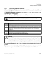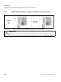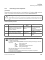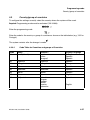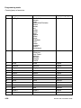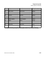
1
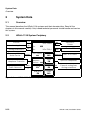
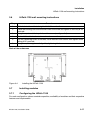
Documentation
HiPath 1100 V7.0
HiPath 1120
Installation Guide
Communication for the open minded
Siemens Enterprise Communications
www.siemens-enterprise.com
Contents
Contents
0
1 Important Information. . . . . . . . . . . . . . . . . . . . . . . . . . . . . . . . . . . . . . . . . . . . . . . . . . 1-3
1.1 Safety Information . . . . . . . . . . . . . . . . . . . . . . . . . . . . . . . . . . . . . . . . . . . . . . . . . . . . 1-3
1.1.1 Safety Information: danger . . . . . . . . . . . . . . . . . . . . . . . . . . . . . . . . . . . . . . . . . . 1-5
1.1.2 Safety Information: warning. . . . . . . . . . . . . . . . . . . . . . . . . . . . . . . . . . . . . . . . . . 1-6
1.1.3 Safety Information: Caution. . . . . . . . . . . . . . . . . . . . . . . . . . . . . . . . . . . . . . . . . . 1-7
1.1.4 General Information . . . . . . . . . . . . . . . . . . . . . . . . . . . . . . . . . . . . . . . . . . . . . . . 1-8
1.1.5 What to do in Case of an Emergency . . . . . . . . . . . . . . . . . . . . . . . . . . . . . . . . . . 1-9
1.1.6 Accident Report. . . . . . . . . . . . . . . . . . . . . . . . . . . . . . . . . . . . . . . . . . . . . . . . . . . 1-9
1.2 Data Protection and Confidentiality . . . . . . . . . . . . . . . . . . . . . . . . . . . . . . . . . . . . . . 1-10
1.3 Structure of this Manual . . . . . . . . . . . . . . . . . . . . . . . . . . . . . . . . . . . . . . . . . . . . . . . 1-11
2 System Data . . . . . . . . . . . . . . . . . . . . . . . . . . . . . . . . . . . . . . . . . . . . . . . . . . . . . . . . 2-12
2.1 Overview . . . . . . . . . . . . . . . . . . . . . . . . . . . . . . . . . . . . . . . . . . . . . . . . . . . . . . . . . . 2-12
2.2 HiPath 1120 System Periphery . . . . . . . . . . . . . . . . . . . . . . . . . . . . . . . . . . . . . . . . . 2-12
3 Installation . . . . . . . . . . . . . . . . . . . . . . . . . . . . . . . . . . . . . . . . . . . . . . . . . . . . . . . . . .
3.1 HiPath 1100 Installation . . . . . . . . . . . . . . . . . . . . . . . . . . . . . . . . . . . . . . . . . . . . . . .
3.2 Installation Procedures . . . . . . . . . . . . . . . . . . . . . . . . . . . . . . . . . . . . . . . . . . . . . . .
3.3 Select the location for installing the equipment . . . . . . . . . . . . . . . . . . . . . . . . . . . . .
3.4 Unpacking system components . . . . . . . . . . . . . . . . . . . . . . . . . . . . . . . . . . . . . . . . .
3.5 Getting to know your systems. . . . . . . . . . . . . . . . . . . . . . . . . . . . . . . . . . . . . . . . . .
3.5.1 HiPath 1120 . . . . . . . . . . . . . . . . . . . . . . . . . . . . . . . . . . . . . . . . . . . . . . . . . . . .
3.6 HiPath 1120 wall mounting instructions . . . . . . . . . . . . . . . . . . . . . . . . . . . . . . . . . . .
3.7 Installing modules . . . . . . . . . . . . . . . . . . . . . . . . . . . . . . . . . . . . . . . . . . . . . . . . . . .
3.7.1 Configuring the HiPath 1100 . . . . . . . . . . . . . . . . . . . . . . . . . . . . . . . . . . . . . . . .
3.7.2 Location of the modules . . . . . . . . . . . . . . . . . . . . . . . . . . . . . . . . . . . . . . . . . . .
3.7.3 Installing modules . . . . . . . . . . . . . . . . . . . . . . . . . . . . . . . . . . . . . . . . . . . . . . . .
3.7.3.1 On the HiPath 1120 . . . . . . . . . . . . . . . . . . . . . . . . . . . . . . . . . . . . . . . . . . .
3.7.4 ADSL Connection in the LAN interface modules. . . . . . . . . . . . . . . . . . . . . . . . .
3.7.4.1 ADSL module . . . . . . . . . . . . . . . . . . . . . . . . . . . . . . . . . . . . . . . . . . . . . . . .
3.7.4.2 SLIMC, SADSLIM modules . . . . . . . . . . . . . . . . . . . . . . . . . . . . . . . . . . . . .
3.7.5 Installing a Baby Board ADSL module . . . . . . . . . . . . . . . . . . . . . . . . . . . . . . . .
3.7.6 Installing an EVM module . . . . . . . . . . . . . . . . . . . . . . . . . . . . . . . . . . . . . . . . . .
3.7.7 Installing a Baby Board VCC module
(Voltage Conditioner Circuitry) . . . . . . . . . . . . . . . . . . . . . . . . . . . . . . . . . . . . . .
3.7.8 Installing a ISDN / S0 module . . . . . . . . . . . . . . . . . . . . . . . . . . . . . . . . . . . . . . .
3.7.9 Installing a CTR- UP0/E module . . . . . . . . . . . . . . . . . . . . . . . . . . . . . . . . . . . . .
3.7.10 Installing a Music module . . . . . . . . . . . . . . . . . . . . . . . . . . . . . . . . . . . . . . . . .
3.8 Installing the power supply . . . . . . . . . . . . . . . . . . . . . . . . . . . . . . . . . . . . . . . . . . . .
3.8.1 On the HiPath 1120. . . . . . . . . . . . . . . . . . . . . . . . . . . . . . . . . . . . . . . . . . . . . . .
3.9 Connections to the System . . . . . . . . . . . . . . . . . . . . . . . . . . . . . . . . . . . . . . . . . . . .
HiPath 1120, Installation Guide
3-13
3-13
3-13
3-14
3-15
3-15
3-15
3-17
3-17
3-17
3-18
3-19
3-19
3-20
3-20
3-20
3-21
3-22
3-23
3-24
3-26
3-27
3-28
3-28
3-29
1
Contents
3.9.1 HiPath 1120 . . . . . . . . . . . . . . . . . . . . . . . . . . . . . . . . . . . . . . . . . . . . . . . . . . . . .
3.10 Installing a USB Interface . . . . . . . . . . . . . . . . . . . . . . . . . . . . . . . . . . . . . . . . . . . . .
3.10.1 On the HiPath 1120 . . . . . . . . . . . . . . . . . . . . . . . . . . . . . . . . . . . . . . . . . . . . . .
3.11 Installing an external Audio Source. . . . . . . . . . . . . . . . . . . . . . . . . . . . . . . . . . . . . .
3.12 Installing a TFE - entrance telephone interface . . . . . . . . . . . . . . . . . . . . . . . . . . . .
3.12.1 Protection of external lines and extensions . . . . . . . . . . . . . . . . . . . . . . . . . . . .
3.13 Installing telephone terminals . . . . . . . . . . . . . . . . . . . . . . . . . . . . . . . . . . . . . . . . . .
3.14 optiPoint Master/Slave telephone HiPath 1120 connections . . . . . . . . . . . . . . . . . .
3.15 Performing a visual inspection . . . . . . . . . . . . . . . . . . . . . . . . . . . . . . . . . . . . . . . . .
3-29
3-31
3-31
3-32
3-32
3-32
3-33
3-34
3-35
4 Programming mode . . . . . . . . . . . . . . . . . . . . . . . . . . . . . . . . . . . . . . . . . . . . . . . . . . .
4.1 Language . . . . . . . . . . . . . . . . . . . . . . . . . . . . . . . . . . . . . . . . . . . . . . . . . . . . . . . . . .
4.2 Country/group of countries . . . . . . . . . . . . . . . . . . . . . . . . . . . . . . . . . . . . . . . . . . . . .
4.2.0.1 Code Table for Countries and groups of Countries. . . . . . . . . . . . . . . . . . . .
4-36
4-36
4-37
4-37
5 Abbreviations . . . . . . . . . . . . . . . . . . . . . . . . . . . . . . . . . . . . . . . . . . . . . . . . . . . . . . . . 5-41
Index . . . . . . . . . . . . . . . . . . . . . . . . . . . . . . . . . . . . . . . . . . . . . . . . . . . . . . . . . . . . . . . . . . 43
2
HiPath 1120, Installation Guide
Important Information
Safety Information
1
Important Information
HiPath 1100 Telecommunications Systems are compatible with TN-S and TN-C-S power
systems featuring a PEN conductor divided into two parts: a safety ground conductor (PE) and
a neutral conductor (N) as defined in IEC 364-3.
!
1.1
Warning
Only service and installation personnel should open the PABX box and/or connect
and handle trunk and extension lines.
Safety Information
The following information is intended for service personnel and authorized technicians.
Read carefully all the information pertaining to this equipment and follow all safety guidelines.
Become familiar with all emergency numbers.
Whenever work conditions are not absolutely safe, make sure to discuss the situation with a
supervisor before starting to work. For example, humidity or risk of an explosion due to the
presence of gas should be talked about before proceeding.
Safety Symbols
The following symbols are used to indicate potential hazards
:
!
Danger
This symbol indicates an imminently hazardous situation which, if
not avoided, will result in death or serious injury.
!
Warning
This symbol indicates a potentially hazardous situation which, if
not avoided, could result in death or serious injury.
Caution
This symbol indicates a potentially hazardous situation which may
lead to a minor to moderate injury or may damage the hardware or
software.
!
This symbol identifies useful information.
HiPath 1120, Installation Guide
1-3
Important Information
Safety Information
Other symbols that indicate potential hazardous situations
Most of these symbols do not appear in this manual but may appear on the equipment.
Electricity
Weight
Heat
Fire
Chemicals
ESD*
Laser
*Electrostatically Sensitive Device
Symbols
The device conforms to the EU directive 1999/5/EU, as attested by the CE mark.
This device has been manufactured in accordance with our certified environmental management system (ISO 14001). This process ensures that energy consumption and the use of primary raw materials are kept to a minimum, thus reducing waste production.
All electrical and electronic products should be disposed of separately from the
municipal waste stream via designated collection facilities appointed by the government or the local authorities.
The correct disposal and separate collection of your old appliance will help prevent potential negative consequences for the environment and human health. It is
a precondition for reuse and recycling of used electrical and electronic equipment.
For more detailed information about disposal of your old appliance, please contact your city office, waste disposal service, the shop where you purchased the
product or your sales representative.
The statements quoted above are only fully valid for equipment which is installed
and sold in the countries of the European Union and is covered by the directive
2002/96/EC. Countries outside the European Union may have other regulations
regarding the disposal of electrical and electronic equipment.
1-4
HiPath 1120, Installation Guide
Important Information
Safety Information
1.1.1
Safety Information: danger
Ground Safety
Ensure that all proper ground connections have been made before operating the system.
Never operate the equipment before connecting the ground wire.
Dangerous Voltages
Voltages higher than 30 VAC (alternating current) or 42 VDC (direct current) are classified as
dangerous voltages (EN 60950).
Damage
●
Replace the power cord immediately if there is any sign of damage.
●
Replace any damaged safety equipment immediately (covers, labels, safety cables).
●
Use Siemens-approved cables and modules only. The use of accessories that are not
recommended for the system may cause it to malfunction.
Make sure power is turned off while equipment is being serviced.
When maintenance services require shutting down the system, make sure to disconnect all
power supplies.
Working on low voltage network circuits
●
Only qualified technical personnel should work on low voltage network systems (100240 V ac).
●
Never work alone when working with high voltage circuits. Make sure there is another
person present who knows the location of the circuit breakers.
●
Never touch live wires that are not properly insulated.
●
Ensure that no other power source is connected to the equipment. Make sure that the
power source being used is protected by means of an additional breaker or fuse.
●
Make sure that no circuit is powered up before you start working on the equipment. Never
assume that all circuits are automatically disconnected every time a breaker or additional
fuse is disconnected.
●
Do not connect or remove telephone lines or circuit boards during a thunderstorm.
●
Always consider the possibility that a leakage current may be present.
●
When working outdoors, never leave the equipment unsupervised.
HiPath 1120, Installation Guide
1-5
Important Information
Safety Information
1.1.2
Safety Information: warning
Hazards when working with large gauge cables
Low voltages and large gauge cables increase the risk of hazardous situations. While large
gauge cables are usually of low voltage, their current values are higher. This results in higher
risk, specifically in the event of a short-circuit.
Protective Clothing/Equipment
●
When working with the equipment, do not wear loose-fitting clothes. Contain long or freeflowing hair.
●
To avoid injury and the risk of short-circuiting, do not wear jewelry, watches with metallic
wristbands, clothing with metallic accessories or rivets when working with the equipment.
●
Always use appropriate eye protection.
●
Wear a safety helmet in hazardous situations where there is a risk of injury from falling
objects.
Safety Measures
●
Shiny or reflective surfaces are conductive. Never touch a live component with a mirror.
This can lead to short-circuiting, which may lead to personal injury.
●
Unless the equipment’s operating instructions specify otherwise, shut-down the power
when working in close proximity to a power supply or DC converter.
●
Do not try to lift heavy objects by yourself.
1-6
HiPath 1120, Installation Guide
Important Information
Safety Information
1.1.3
Safety Information: Caution
Checking and Measuring Voltage
●
Check rated voltage for recommended system installation.
●
Proceed very carefully when making measurements on live components or when servicing
equipment with the power on.
Damage
Only use tools and equipment that are in perfect condition. Do not operate equipment that is
damaged. Report any problems to your supervisor.
ESD Protection for Components (ESD)
To protect an electrostatically sensitive device:
●
Wear an anti-static wristband before servicing or maintaining the system or any of its
modules.
●
Always transport the system or its modules in appropriate protective packaging.
●
When working with boards, always place them on a grounded conductive base.
●
Use grounded soldering irons with only.
Layout of the Cables
Position cables in a manner to prevent damaging them or causing accidents and injuring
people.
Batteries
Batteries that are not correctly installed or batteries replaced with a different type than the one
specified can be an explosion hazard. Replace battery with an identical type of battery or use
a type recommended by Technical Support. Dispose of used batteries according to your
countries laws and regulations.
HiPath 1120, Installation Guide
1-7
Important Information
Safety Information
1.1.4
General Information
Line/Cable Connections
●
All cables coming out of the system must be protected along their entire path inside
conduits, ducts or other appropriate routes of conveyance.
●
Cables must be connected only to their specified connections points.
Location of Safety Equipment
Once maintenance is finished, return all safety equipment to its proper location.
Inspecting your Tools
Inspect tools regularly. Only tools in perfect condition should be used.
Condensation
When moving the equipment from a cold environment to a location at room temperature, take
into consideration “Environmental conditions” to prevent the occurrence of condensation. Wait
until the equipment is at room temperature and completely dry before turning it on.
Wall Mounting
●
Some types of walls (e.g., drywall) have limited weight-bearing capacity. Before installing
equipment in wall-mount configuration, make sure the wall can support the weight.
●
Examine the condition of the walls to ensure that there are no cracks or damage that
indicates the presence of humidity.
Flammable Materials
Do not store flammable materials in close proximity to the equipment.
Hazards at the location of operation
●
Ensure that the location is well lit.
●
There is a higher risk of an accident occurring in or near unorganized premises.
1-8
HiPath 1120, Installation Guide
Important Information
Safety Information
1.1.5
What to do in Case of an Emergency
Procedures to follow during Accidents
●
In the event of an accident stay calm and proceed with caution.
●
Turn off the power before touching the victim of an electrical accident.
●
If the power cannot be shut down immediately, use an object made of a non-conductive
material such as wood to touch the victim and isolate him/her from any electrical current.
First Aid
●
You should have knowledge of the first aid principles to follow for victims of electric shock.
In the event of an emergency of this kind, it is critical to know CPR in order to help victims
who have suffered cardiac arrest or who have stopped breathing. It is also essential to have
basic knowledge of the kind of first aid administered to burn victims.
●
If the victim is not breathing, perform mouth-to-mouth or mouth-to-nose resuscitation
immediately.
●
If you have had proper training and the victim’s heart is not beating, promptly commence
a heart massage.
Emergency Call
Call an ambulance or doctor immediately and provide the following information calmly and
rationally:
●
Where did the accident occur?
●
What happened?
●
What type of injuries were sustained?
Finally, be ready to provide any additional information needed for rendering emergency
services.
1.1.6
Accident Report
●
Promptly report to a supervisor all accidents, near-accidents and potential hazards.
●
Report all electrical shocks, even minor ones.
HiPath 1120, Installation Guide
1-9
Important Information
Data Protection and Confidentiality
1.2
Data Protection and Confidentiality
Handling of Personal Information
This telephone exchange uses and processes personal information (call detail records, display
messages, and customer data records, for instance).
Comply with all local and country-specific laws and regulations concerning use and protection
of such information.
Information Protection laws are designed to prevent violation of individual privacy rights through
misuse of personal data.
By safeguarding data against misuse during all stages of processing, information protection
laws protects your rights as well as those of third parties
Guidelines for Siemens Employees
Siemens company policy and procedures require secure business practices and employee
data confidentiality.
The following rules must be strictly followed in order to ensure compliance with job-related
statutory requirements (be they company functions or outsourced maintenance and
management). This serves to safeguard our customers’ interests and provide additional
personal protection.
Guidelines for Handling Information
A conscientious, responsible approach helps to protect and safeguard information:
●
Make sure that only authorized personnel have access to customer information.
●
Always use password assignment features; no exceptions allowed. Never disclose
passwords to unauthorized personnel.
●
Ensure that no unauthorized personnel are able to process (store, modify, transmit,
override, delete) or make use of customer information.
●
Block all access by unauthorized personnel to data such as backup disks or record
printouts.
●
See that all unnecessary recording media are completely destroyed and that no
documents are stored or left in unsecured places.
●
Working together with the customer builds trust.
1-10
HiPath 1120, Installation Guide
Important Information
Structure of this Manual
1.3
Structure of this Manual
Introduction
This manual provides information about the HiPath 1100 Communications Systems.
This manual was designed to provide information in information mapping format. It is divided
into sections and units that present, as clearly as possible, all steps required to perform specific
tasks when operating the system. It makes it easy for technical personnel to find the information
needed and learn it quickly.
This Installation Gude is an extract of the HiPath 1100 Service Manual which describes all
Models of the HiPath 1100 family. More details and all Chapters could be found there.
Main sections of this Manual.
●
Chapter 2, “System Data” provides a overview of the HiPath 1100 system.
●
Chapter 3, “Installation” provides information on how to setup and install the HiPath 1100,
including recommendations and important notes.
HiPath 1120, Installation Guide
1-11
System Data
Overview
2
System Data
2.1
Overview
This manual describes the HiPath 1120 systems and their characteristics. Read all the
chapters in this manual carefully. Only trained technical personnel should handle and service
this system.
2.2
HiPath 1120 System Periphery
Profiset
External analog lines
Analog extensions
Sensor and Relay
Audio Device
c/d
a/b
a/b
S1/RL1
Internal entrance
telephone Extension
Basic Access
(Public Network)
ISDN
S0
4x
Mini DIN-6
MO
V.24
Service PC
Printer
2x
MB
Mini DIN-4
MO
USB
Service PC
8x
Music module
MO
ADSL
MO
Entrance
telephone
interface MO
UP0/E
EB
2 x S0
EB
204
EB
CTR-UP0/E
EVM
MO
EB
Figure 2-1
2-12
Ethernet
LAN
HUB - 4 PC Ports
optiPoint telephones
a/b
External analog lines
Analog extensions
HiPath 1120 System Periphery
HiPath 1120, Installation Guide
Installation
HiPath 1100 Installation
3
Installation
3.1
HiPath 1100 Installation
About this Chapter
This chapter contains information on:
●
Installing the interface HiPath 1100. More information on additional equipment and
expansions can be found in the Service Manual
●
Configuration (installation of modules).
!
Danger
Only authorized technical personnel should install this system.
3.2
Installation Procedures
!
Warning
●
Before installing the equipment, please read carefully all information and
recommendations provided in Chapter 1, “Important Information”
●
When connecting to live terminal equipment lines powered by an external AC
power source, the maximum number of terminal equipment allowed is 14 per
system. Exceeding this limit may damage the equipment and put user safety at
risk.
●
Check whether all AC and DC connections of the cables, modules and chassis
of the HiPath 1100 are correctly and properly connected before connecting the
client interface.
Step
Installation procedures (Information)
1.
“Select the location for installing the equipment”
(Usually already defined)
3-14
2.
“Unpacking system components”
3-15
3.
“Getting to know your systems”
3-15
4.
“HiPath 1120 wall mounting instructions”
3-17
5.
“Installing modules”
3-17
6.
“Installing the power supply”
3-28
HiPath1120, Installation Guide
3-13
Installation
Select the location for installing the equipment
Step
Installation procedures (Information)
7.
“Connections to the System”
3-29
8.
“Installing a USB Interface”
3-31
9.
“Installing an external Audio Source”
3-32
10.
“Installing a TFE - entrance telephone interface”
3-32
11.
“Installing telephone terminals”
3-33
12.
“Performing a visual inspection”
3-35
Table 3-1
!
3.3
HiPath 1100 - Equipment installation procedures
Caution
Always use an anti-static wrist band when working with the HiPath 1100 systems
(particularly when handling the modules). Make sure the wrist band is grounded.
Select the location for installing the equipment
Installation Location
The system’s installation site has been previously selected and agreed to by the client.
The following precautions must be taken:
●
Do not expose the equipment to any external heat source (e.g., sunlight, heaters, etc.)
●
Do not expose the equipment to excess dust
●
Do not install the equipment in areas where there is a risk of condensation when the
equipment is in use. If condensation occurs, dry the equipment before starting operation.
●
Do not install inside closets.
●
The power outlet for connecting the system’s power supply must be located close to the
equipment and must be easily accessible.
●
Follow all environmental guidelines described in the chapter “System Data“.
●
Do not install in vibrating walls.
!
3-14
Warning
When using the RSA version, extension lines with a C/D interface must only be installed indoors. Only regular extensions (without a C/D interface) can be installed
outdoors.
HiPath1120, Installation Guide
Installation
Unpacking system components
3.4
Unpacking system components
Procedure
Step
Procedure
1.
Check to see that all components listed on the receipt are included in the package.
2.
Inspect all items for any damage that may have occurred during transportation. If
any damage occurred, report it immediately to the place of purchase.
3.
Discard packaging materials according to national environmental regulations.
!
Warning
Use only equipment and systems that are in perfect condition. Never operate a damaged system.
3.5
Getting to know your systems
3.5.1
HiPath 1120
Dimensions of the HiPath 1120
Figure 3-1
Dimensions of the HiPath 1120
HiPath1120, Installation Guide
3-15
Installation
Getting to know your systems
Opening the Main Distribution Frame
Figure 3-2
Opening the HiPath 1120 Main Distribution Frame
Location of components
Figure 3-3
3-16
System installation overview HiPath 1120
HiPath1120, Installation Guide
Installation
HiPath 1120 wall mounting instructions
3.6
HiPath 1120 wall mounting instructions
Step
Procedure
1.
Drill a hole in the wall at a height of 4.10 ft from the floor.
2.
Place the bushing over the hole then insert the screw and tighten it until only 0.19"
protrude.
3.
Hang the system at the top of ➀, on the screw (see figure 3-4).
4.
Mark additional holes for washers ➁ and remove the system.
5.
Drill the remaining holes as marked, install washers and screws then tighten them
letting 0.19" protrude.
6.
Hang the system again and align it by tightening the lower screws.
Back of the enclosures
Figure 3-4
Installing the HiPath 1120
3.7
Installing modules
3.7.1
Configuring the HiPath 1100
For each configuration, please consider capacities, availability of modules and their respective
features and requirements.
HiPath1120, Installation Guide
3-17
Installation
Installing modules
To help you configure the systems, we suggest that you use the Service Manual, the HiPath
1100 Manager, in off-line mode, to obtain a visual illustration of the module locations and
external lines and the resulting numbering plan (see Help - Advanced Configuration/PABX
Information for further information).
3.7.2
Location of the modules
Installation information
The MB and the modules in the HiPath 1120 system are interconnected with a flatcable (they
must be passed through the ferrite provided) and/or a pin bar.
!
Warning
Insert modules only when the power supply is turned OFF.
Figure 3-5
3-18
Location of modules on HiPath 1120
HiPath1120, Installation Guide
Installation
Installing modules
3.7.3
Installing modules
3.7.3.1
On the HiPath 1120
Installation Procedures
Step
*
Procedure
1.
Turn off the power supply.
2.
Remove the system’s cover
3.
Insert the module into one of the slots shown in figure 3-5.
4.
Underside: To install the LAN Interface Module or Music Module, lift the top part
(MB) of the system and use the pin bar to connect with X1 position of the LAN
Interface Module or X2 position of the Music Module.
5.
Top side: Interconnect the module and the MB using the flat cable/s provided, taking
care to pass it through the ferrite (see figure 3-5).
6.
Connect to the module’s MDF Connectors (see figure 3-14).
7.
Reassemble the entire set.
8.
“Performing a visual inspection” on page 3-35.
9.
Turn on the power supply.
10.
Configure the required data (see Service Manual).
11.*
Using Manager application go to: Advanced tab, > PBX Information tab, > Slot
Allocation tab;
Select the Clear All Slots checkbox;
Update the HiPath System;
Reset the HiPath System.
This is necessary only if you have changed the type of the modules installed in your system.
HiPath1120, Installation Guide
3-19
Installation
Installing modules
3.7.4
ADSL Connection in the LAN interface modules
3.7.4.1
ADSL module
Connection procedure
Step
Procedure
1.
Connect the carrier’s ADSL line to slot 1 and 2 of the X2 Connector.
2.
Connect slots 3 and 4 of the X2 Connector to the external line input for the HiPath
1100.
3.
Connect your network cables to the HUB (J3, J5, J6 and J7 Connectors).
3.7.4.2
SLIMC, SADSLIM modules
Connection procedure
Step
Procedure
1.
Connect the carrier’s ADSL line to slot 1 and 2 of the X11.
2.
Connect slots 3 and 4 of the X11 Connector to the external line input of the HiPath
1100.
3.
Connect the cables of your network PCs to the HUB (X2, X3, X4 and X5
Connectors).
Figure 3-6
3-20
ADSL Connection on the HiPath 1120
HiPath1120, Installation Guide
Installation
Installing modules
3.7.5
Installing a Baby Board ADSL module
Installation Procedures
Step
Procedure
1.
Select the SLIMC module. The Baby Board is a Modem for ADSL over POTS and
will not support ADSL over ISDN (an external Modem must be used in case of ADSL
over ISDN).
2.
Attach the separators provided with the module.
3.
Attach the Baby Board ADSL module to the separators.
4.
Connect the cable of the Ethernet Interface to the X6 Connectors.
5.
Connect the cable of the ADSL line to the X14 Connectors.
6.
Connect the power cable of the module Baby Board ADSL to the X7 Connectors.
7.
“Performing a visual inspection” on page 3-35.
8.
Configure the required data (see Service Manual).
Assembly Diagram
Baby Board ADSL Modul
(for ADSL over POTS only)
X14
X6
X7
X14
X6
X7
Figure 3-7
Installing a Baby Board ADSL module HiPath 1120
HiPath1120, Installation Guide
3-21
Installation
Installing modules
3.7.6
Installing an EVM module
Installation Procedures
Step
Procedure
1.
Turn off the power supply.
2.
Remove the system’s cover
3.
Attach the separator provided with the module to the MB.
4.
Attach the module to the MB’s pin Connector and to the separator.
5.
Reassemble the entire set.
6.
“Performing a visual inspection” on page 3-35.
7.
Turn on the power supply.
8.
Configure the required data (see Service Manual).
Assembly Diagram
Figure 3-8
3-22
Installing an EVM module HiPath 1120
HiPath1120, Installation Guide
Installation
Installing modules
3.7.7
Installing a Baby Board VCC module
(Voltage Conditioner Circuitry)
Installation Procedures
Step
Procedure
1.
Turn off the power supply.
2.
Remove the system’s cover
3.
Attach the separator provided with the module to the MB.
4.
Attach the module to the MB’s pin Connector and to the separator.
5.
Reassemble the entire set.
6.
“Performing a visual inspection” on page 3-35.
7.
Turn on the power supply.
8.
Configure the required data (see Service Manual).
Assembly Diagram
Figure 3-9
Installing a Baby Board VCC module on the HiPath 1120
HiPath1120, Installation Guide
3-23
Installation
Installing modules
3.7.8
Installing a ISDN / S0 module
Installation Procedures
Step
Procedure
1.
Turn off the power supply.
2.
Remove the system’s cover
3.
Attach the module to the corresponding Connector on the MB
4.
Reassemble the entire set.
5.
“Performing a visual inspection” on page 3-35.
6.
Turn on the power supply.
7.
Configure the required data (see Service Manual).
Assembly Diagram
X1
Connection to the MB through a pin Connector
X2
Port 1 - RJ 45
X3
Port 2 - RJ 45
Figure 3-10
3-24
HiPath 1120 S0 module
HiPath1120, Installation Guide
Installation
Installing modules
HiPath 1120 S0 module jumpers
X2 - Port 1
Configuration
X3 - Port 2
Jumper Pos.
Configuration
Jumper Pos.
Extern S0 Trunk
(Point to Point,
Point to Multipoint)
X4 = 1-2
X5 = 1-2
Extern S0 Trunk
(Point to Point,
Point to Multipoint)
X6 = 1-2
X7 = 1-2
Intern
NOT
PERMITTED
Intern S0-BUS
X6 = 2-3
X7 = 2-3
S0-BUS
HiPath1120, Installation Guide
3-25
Installation
Installing modules
3.7.9
Installing a CTR- UP0/E module
The line length of the analog stations is restricted to 100m when using comfort
telephones.
Installation Procedures
Step
Procedure
1.
Turn off the power supply.
2.
Remove the system’s cover
3.
Attach the module to the corresponding Connector on the MB
4.
Reassemble the entire set.
5.
“Performing a visual inspection” on page 3-35.
6.
Turn on the power supply.
7.
Configure the required data (see Service Manual).
Assembly Diagram
Figure 3-11
3-26
Installing a CTR- UP0/E HiPath 1120 module
HiPath1120, Installation Guide
Installation
Installing modules
3.7.10
Installing a Music module
Installation Procedures
Step
Procedure
1.
Turn off the power supply.
2.
Remove the system’s cover
3.
Raise the system’s top slot (MB).
4.
Insert the module in the slot shown on figure 3-12.
5.
Attach the MB to the module.
6.
Make the connections to the appropriate module Connector.
7.
Reassemble the entire set.
8.
“Performing a visual inspection” on page 3-35.
9.
Turn on the power supply.
10.
Configure the required data (see Service Manual).
Assembly Diagram
Figure 3-12
Installing a Music module HiPath 1120
HiPath1120, Installation Guide
3-27
Installation
Installing the power supply
3.8
Installing the power supply
Introduction
Before connecting the power supply to the system, see Service Manual.
3.8.1
On the HiPath 1120
Installation Procedures
Step
Procedure
1.
Check network voltage
2.
If the voltage is within the power supply’s voltage range, connect the power supply.
3.
“Performing a visual inspection” on page 3-35
4.
Configure the required data (see Service Manual).
!
Warning
Use the cable of the power supply to turn system power on or off.
Figure 3-13
3-28
Installing a power supply on the HiPath 1120
HiPath1120, Installation Guide
Installation
Connections to the System
3.9
Connections to the System
Introduction
Attach cables to the system’s Main Distribution Frame (MDF) and route them through the
conduits and openings to reach the carrier’s main telephone distribution cabinet. Below are
some examples of configurations.
3.9.1
HiPath 1120
Example
*The installation of a Profiset 3030 system
telephone requires a CD pair in conjunction with an A/B extension
slot (see “Installing telephone terminals” on page 3-33).
Figure 3-14
Distribution of extensions on the HiPath 1120 MDF
.
!
Warning
When using the RSA version, extension lines with a C/D interface must only be
installed indoors. Only regular extensions (without a C/D interface) can be installed
outdoors.
HiPath1120, Installation Guide
3-29
Installation
Connections to the System
When using Expansion module UP0/E, Profiset 3030 system telephone or optiPoint
could be assigned as attendant but the c/d lines will be reduced from 4 to 2 cd lines.
The line length of the analog stations is restricted to 100m when using comfort
telephones.
Slot
MB
Position of
the
Internal #
Slot
01
801
02
802
Position
1
A/B
Slot
Position 2
A/B
Table 3-2
3-30
Position
of the extension
Position
of the
trunk
1
11
2
12
3
13
4
14
5
15
6
16
7
17
8
18
Position
of the
extension
Internal #
EB 204 module
05
805
06
806
13
23
14
24
15
25
16
26
A/B
Position
of the
trunk
Position
Internal #
of the
EB 204 module
exten-
03
803
04
804
9
19
10
20
11
21
12
22
Example of the location of extensions on the HiPath 1120 Main Distribution
Frame
HiPath1120, Installation Guide
Installation
Installing a USB Interface
3.10
Installing a USB Interface
Introduction
To connect a PC to the HiPath 1100 using a USB interface you must have a USB adapter cable.
This interface allows you to use certain applications developed specifically for configuring and
managing user features.
3.10.1
On the HiPath 1120
Figure 3-15
Illustration of USB cable connection
Connections
Step
Procedure
1.
Plug the USB adapter cable (with the male Mini DIN Connector) into the 4-pin Mini
DIN Connector on the motherboard (Figure 3-15).
2.
Connect the A to B Standard end of the USB cable to the USB adapter, and connect
the other end to the computer or modem.
3.
See System Programming Mode in the Service Manual.
HiPath1120, Installation Guide
3-31
Installation
Installing an external Audio Source
3.11
Installing an external Audio Source
The HiPath 1100 systems provide connections for audio devices, such as radios, tuners, CD,
MD, and others.
●
HiPath 1120
The audio source must be connected to a music optional module using an RCA Connector
in slot X1 (see Figure 3-14 on page 3-29).
3.12
Installing a TFE - entrance telephone interface
3.12.1
Protection of external lines and extensions
The primary protection of external lines and extensions must be provided by grounding the
system through a separate cable (minimum section = 2.5 mm 2) set up exclusively for the
protection of the telephone system. The secondary protection of external lines and extensions
is between wires A and B.
For primary protection for a distribution box that is external to the PABX use a MPT250 shield
with two PTCs (A and B wires) for overcurrent protection along with a gas capsule connected
to the ground wire through a separate cable that is independent of the cable used for grounding
the power supply.
The connection between the HiPath 1100 system and the distribution box must be made using
multipair cables, preferably foil shielded. This type of flat cable has a special grounding wire that
must be connected to the safety ground, but only at the distribution box end
.
For the RSA version the primary protection for external lines and extensions must
be provided according to local regulations.
Figure 3-16
3-32
Protection and grounding connection diagram
HiPath1120, Installation Guide
Installation
Installing telephone terminals
3.13
Installing telephone terminals
A Profiset 3030 System Telephone has four wires (A, B, C, D), two used for voice (A, B), and
two for data (C, D).
An optiPoint-type system telephone has four wires (A, B, C, D), two of which (A, B) are
required for voice communications.
A Standard Telephone (DP/MF) has only two wires (A, B), both used for voice.
Standard Telephones (DP/MF) and optiPoint telephones must be connected to the
HiPath 1100 system using wires A and B only. Do not use wires C and D.
Installation Procedures
Step
Procedure
1.
Install telephone jacks at the extensions.
2.
Connect each extension jack to the desired A/B slot on the Main Distribution Frame.
3.
Profiset 3030 system telephones are preset at factory default for C/D pairs.
If necessary, choose a different C/D pair, then program the new C/D interface
assignment.
4.
Install the telephone sets.
5.
“Performing a visual inspection” on page 3-35.
6.
Configure the required data (see Service Manual).
Warning
!
Profiset 3030 system telephones are powered through the C and D wires. Take the
necessary precautions to avoid short circuits at the interconnect block. If a short circuit occurs between wires C and D, the interface’s protection will take the extension
out of service. To activate the extension again, remove the short, disconnect the system telephone then reconnect it. The interface should then start operating normally.
For 2-wire analog telephone sets (A, B) a momentary short-circuit should not cause any
problem.
The maximum distance for installing a Profiset 3030 system telephone using a two-pair cable
with a 0.4 mm2 copper wire is 0.3 miles and for standard telephones it is 1.5 miles.
HiPath1120, Installation Guide
3-33
Installation
optiPoint Master/Slave telephone HiPath 1120 connections
3.14
optiPoint Master/Slave telephone HiPath 1120 connections
Figure 3-17
!
3-34
optiPoint Master/Slave telephone HiPath 1120 connections
Important
When there are more than 4 optiPoint 500 (Master or Slave) telephones on the HiPath 1120 system, an additional power supply must be used. (see Service Manual).
HiPath1120, Installation Guide
Installation
Performing a visual inspection
3.15
Performing a visual inspection
Introduction
Before starting up the system, perform a visual inspection of all hardware, cables and power
supply. This procedure should be performed with the entire system turned OFF.
.
Warning
!
Check whether all AC and DC connections of the cables, modules and chassis of the
HiPath 1100 are correctly and properly connected before connecting the client interface.
Visual inspection procedure
Step
Procedure
Help/
Notes
Measurements
1.
Compare the installation position of Module installation Make the appropriate
modules on the slots against the
diagram.
corrections
installation diagram.
to the modules and notify
the person in charge.
2.
Check to see that all modules are
securely and properly attached.
See “System Data” Attach or secure modules
on page 2-12.
as needed.
3.
Check the network’s line voltage.
Multimeter.
Table 3-3
Verify voltage at power
source.
Visual inspection procedure.
In case of the first usage of the UP0/E Option and your optiPoint starts with all LED's
blinking please follow the instruction below:
1. Power on the System
2. Initiate a reset to factory default command by dialing and waiting for acknowledge tone):
*95
enter program state
31994
enter password
199
reset to factory default command
31994
enter password again
After the reset (please wait for final system initialization)
3.Power off the System
4.Disconnect the analoge Phone and connect your optiPoint as planned.
5.Continue with your installation.
HiPath1120, Installation Guide
3-35
Programming mode
Language
4
Programming mode
You can change the default settings of the HiPath 1100 to fit your needs. An MF-type or system
telephone can be used for this purpose, or a PC with the HiPath 1100 Manager administration
software installed.
The instructions that follow refer to the factory default settings. For further
information please refer to the HiPath 1100 Programming Manual.
4.1
Language
Defines the language for displaying messages on the system telephone display. This field is not
automatically updated since it is based on the country option selected. When the Language
field is changed the Country is not automatically changed. It is possible, therefore, to select a
country with a different default language. Example: Country: Brazil, Language: English.
Required: Programming mode must be activated (*95 31994).
ejh w
Enter the programming code.
p w
Select the language for displaying messages.
d=
Custom
e=
Portuguese
f=
Spanish
g=
English (default)
h=
French
i=
Italian
j=
Turkish
k=
German
l=
Dutch
w
Initial status for programming mode.
4-36
HiPath1120, Installation Guide
Programming mode
Country/group of countries
4.2
Country/group of countries
To configure the settings correctly select the country where the system will be used.
Required: Programming mode must be activated (*95 31994).
eji w
Enter the programming code.
p w
Enter the code for the country or group of countries as shown on the table below (e.g., "03" for
Portugal).
w
The system restarts after the change is made.
4.2.0.1
Code Table for Countries and groups of Countries.
Code
Group
Countries
Display Language
01
Brazil (default)
Brazil
Bolivia
Paraguay*
Portuguese
Spanish
Spanish
02
Argentina
Argentina
Spanish
03
Portugal
Portugal
Portuguese
04
Chile
Chile
Spanish
05
Venezuela
Venezuela
Spanish
06
Mexico
Mexico
Spanish
07
Vietnam
Vietnam
English
08
IM Spanish
Columbia
Uruguay
Ecuador
Central
America
Indonesia**
Spanish
HiPath1120, Installation Guide
English
4-37
Programming mode
Country/group of countries
Code
Group
Countries
Display Language
09
IM English
Saudi Arabia
Bahrain
Egypt
United Arab Emirates
Ghana
Yemen
Iran
Jordan
Kuwait
Libya
Nigeria
Oman
Kenya
Zimbabwe
Syria
Sudan
Tanzania
Serbia/
Montenegro
English
10
IM French
Algeria
Cameroon
Ivory Coast
Lebanon
Morocco
Senegal
Tunisia
French
11
China
China
English
12
Malaysia
Malaysia
English
13
Singapore
Singapore
English
14
Thailand
Thailand
English
15
Greece
Greece
English
16
India
India
English
17
Pakistan
Pakistan
English
18
Spain
Spain
Spanish
19
Russia
Russia
English
20
Ukraine
Ukraine
English
21
Peru
Peru
Spanish
22
China 2
China 2
English
23
Philippines
Philippines
English
4-38
HiPath1120, Installation Guide
Programming mode
Country/group of countries
Code
Group
Countries
Display Language
24
Canada
Canada
English
25
South Africa
South Africa
English
26
Turkey
Turkey
English
27
Latvia
Latvia
English
28
Lithuania
Lithuania
English
29
Italy
Italy
English
30
Australia
Australia
English
31
United Kingdom
United Kingdom
English
33
France
France
French
34
Korea
Korea
English
35
Germany
Germany
German
36
Netherland
Netherland
Dutch
37
Belgium
Belgium
Dutch
French
* For Bolivia and Paraguay, set "01=Brazil" for country/country group then "02=Spanish" for language.
** For Indonesia set "08=Intern. Spanish" for country/group of countries. then "03=English" for language.
HiPath1120, Installation Guide
4-39
Programming mode
Country/group of countries
4-40
HiPath1120, Installation Guide
Abbreviations
5
Abbreviations
General list
This list presents the abbreviations used in this manual.
Table 5-1
Abbreviation
ACD
ACS
ADSL
ARG
BRA
CAPI
CAS
CD
CHN
CLIP
CND
COS
CTI
CTS
DID
DISA
DP
DSR
DTMF
DTR
E1
EB
ESD
ETSI
EWAKO
GND
HKZ
IM
Abbreviations
Meaning
Automatic Call Distribution
Alternative Carrier Selection
Asymmetric Digital Subscriber Line
Argentina
Brazil
Common ISDN Application Program Interface
Channel-Associated Signaling
Carrier Detect
China
Calling Line Identification Presentation
Canada
Class of Access (Class of Service)
Computer Telephony Integration
Clear To Send
Direct Inward Dialing
Direct Inward System Access
Dial pulse telephone
Data Send Ready
Dual Tone Multiple Frequency
Data Terminal Ready
Primary Access
Expansion Board
Electrostatic Discharge
European Telecomunications Standard Institute
External Toll Restriction / Denied Numbers and Permission Lists
Ground
Main Station Interface / Analog Trunk
International Market
HiPath 1120, Installation Guide
5-41
Abbreviations
Table 5-1
Abbreviation
IND
ISDN
LAN
MB
MDF
MF
MO
MOH
MSN
NT
PABX
PC
PEN
PMP
PP
PSU
RSA
RTC
RTS
RUF
RxD
S0
SPA
SW
TAPI
TFE
TN-C-S
TN-S
TxD
UCD
USB
VMIe
5-42
Abbreviations
Meaning
India
Integrated Services Digital Networks
Local Area Network
Basic Module
Main Distribution Frame
Analog Multifrequency telephone
Optional Module
Music on Hold
Multiple Subscriber Number
Network Terminator
Private Automatic Branch Exchange
Personal Computer
Protection Conductor plus Neuter conductor
Point Multipoint Connection
Point to Point Connection
Power supply unit
Republic of South Africa
Real time clock
Request To Send
Ring
Receive Data
Basic Access
Spain
Software
Telephony Applications Programming Interface
Türfernsprecher (Entrance Telephone)
Power supply systems with Phase, Neuter (grounded) and Ground
Power supply systems with Phase, Neuter (grounded)
Transmit Data
Universal Call Distribution
Universak Serial Bus
Extended voice mail interface
HiPath 1120, Installation Guide
Index
Z
A
Accident Report 1-9
C
CE mark 1-4
Connecting extensions to the system’s Internal MDF 3-29
Country 4-37
D
Data Protection and Confidentiality 1-10
Dimensions of the HiPath 1120 system 3-15
S
Safety Information 1-3
caution 1-7
warning 1-6
Safety information
danger 1-5
Safety Symbols 1-3
Select the location for installing the equipment 3-14
System Data 2-12
U
Unpacking system components 3-15
W
What to do in Case of an Emergency 1-9
G
Getting to know your systems 3-15
H
HiPath 1100 System Installation 3-13
HiPath 1100 System Periphery 2-12
I
Important Information 1-3
Installation Procedures 3-13
Installing a USB Interface 3-31
Installing an entrance telephone 3-32
Installing an external Audio Source 3-32
Installing expansion and optional modules 317
Installing modules 3-19
Installing telephone terminals 3-33
Installing the Power Supply Unit (PSU) 3-28
L
Language 4-36
P
Performing a visual inspection 3-35
Programming mode 4-36
Protection of external lines and extensions 332
HiPath 1120, Installation Guide
43
44
HiPath 1120, Installation Guide
Copyright © Siemens Enterprise
Communications GmbH & Co. KG 06/2008
Hofmannstr. 51, D-80200 München
Siemens Enterprise Communications GmbH & Co. KG
is a Trademark Licensee of Siemens AG
Reference No.: A31003-K1270-J100-1-7631
Communication for the open minded
Siemens Enterprise Communications
www.siemens-enterprise.com
The information provided in this document contains
merely general descriptions or characteristics of
performance which in case of actual use do not
always apply as described or which may change as
a result of further development of the products. An
obligation to provide the respective characteristics
shall only exist if expressly agreed in the terms of
contract. Subject to availability. Right of modification reserved. The trademarks used are owned by
Siemens Enterprise Communications GmbH & Co.
KG or their respective owners.