1
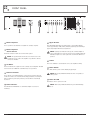
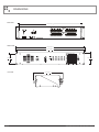
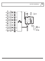
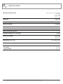
INSTALLATION AND OPERATION MANUAL
AMIS MP8
8 ZONE MONITOR PANEL
IMPORTANT SAFETY INFORMATION
PRÉCAUTIONS DURANT UTILISATION
1. Read these instructions.
1. LISEZ ces instructions.
2. Keep these instructions.
2. Tenez ces instructions.
3. Heed all warnings.
3. Notez tous les avertissements.
4. Follow all instructions.
4. Suivez toutes les avertissements.
5. Do not use this apparatus near water.
5. N’utilisez pas ce produit près de l’eau (la piscine, la plage, le lac, etc.).
6. Clean only with dry cloth.
6. Nettoyez seulement avec une étoffe sèche.
7. Do not block any ventilation openings. Install in accordance with the
manufacturer’s instructions.
7. Ne bloquez aucuns troux de ventilation. Installez en accord avec les
instructions du manufacturier.
8. Do not install near any heat sources such as radiators, heat registers,
stoves, or other apparatus (including amplifiers) that produce heat.
8. N’installez près aucunes sources de chaleur comme radiateurs, registres
de chaleur, fours ou les autres équipements (y compris amplificateurs) qui
produisent la chaleur.
9. Do not defeat the safety purpose of the polarized or grounding-type
plug. A polarized plug has two blades with one wider than the other. A
grounding type plug has two blades and a third grounding prong. The wide
blade or the third prong are provided for your safety. If the provided plug
does not fit into your outlet, consult an electrician for replacement of the
obsolete outlet.
10. Protect the power cord from being walked on or pinched particularly
at plugs, convenience receptacles, and the point where they exit from
the apparatus.
11. Only use attachments/accessories specified by the manufacturer.
12. Use only with the cart, stand, tripod, bracket, or table specified by the
manufacturer, or sold with the apparatus. When a cart is used, use caution
when moving the cart/apparatus combination to avoid injury from tip-over.
13. Unplug this apparatus during lightning storms or when unused for long
periods of time.
14. Refer all servicing to qualified service personnel.
Servicing is required when the apparatus has been
damaged in any way, such as power-supply cord or plug
is damaged, liquid has been spilled or objects have fallen
into the apparatus, the apparatus has been exposed to
rain or moisture, does not operate normally, or has been dropped.
15. This appliance shall not be exposed to dripping or splashing water and
that no object filled with liquid such as vases shall be placed on the
apparatus.
16. Plug this apparatus to the proper wall outlet and make the plug to be
disconnected readily operable.
17. Mains plug is used as disconnected device and it should remain readily
operable during intended use. In order to disconnect the apparatus from
the mains completely, the mains plug should be disconnected from the
mains socket outlet completely.
18. WARNING: To reduce the risk of fire or electric shock, do not expose this
apparatus to rain or moisture.
19. An appliance with a protective earth terminal should be connected to a
mains outlet with a protective earth connection.
20. The apparatus should be disconnected from the mains completely before
speaker wiring. The speaker output should be proper protected from
direct contact and pay attention to speaker connections, terminals and
speaker wiring during normal operation.
PAGE 2
9. Ne défaites pas le but de sécurité de la fiche polarisée ou base-type. Une
fiche polarisée a deux tranchants avec un plus large que l’autre. Une fiche
de base type a deux a deux tranchants et une troisième pointe de base,
le tranchant large ou la troisième pointe est fourni pour votre sécurité. Si
la fiche donnée ne conforme pas votre prise de contact, consultez un
électricien pour remplacement de la prise de contact obsolète.
10. Protegez le cordon de secteur contre être marchée dessus ou pincez en
particulier aux fiches, aux douilles de convenance, et au point où ils
sortent de l’appareil.
11. Seulement utilisez attachements/accessoires spécifiés par le manufacturier.
12. Utilisez seulement avec un chariot, un stand, un trépied, un support ou
une table indiquée par le manufacturier, ou vendue avec l’appareil. Quand
un chariot est utilisé, faites attention en déplaçant la combinaison
d’appareil/chariot pour éviter de se déséquilibrer.
13. Arrachez la fiche du dispositif durant éclair et orage ou quand pas utilisé
pour longues périodes de temps.
14. Référez au personnel qualifié de service pour toutes
réparations. La réparation est donnée quand le système
a été endommagé à n’importe façon, par exemple un fil
ou une fiche endommagé(e) de la source d’alimentation.
Avoir été exposé à pluie ou humidité, n’opère pas
normalement, ou avoir été tombé.
15. L’appareil ne doit pas être exposé aux écoulements ou aux éclaboussures
et aucun objet ne contenant de liquide, tel qu’un vase, ne doit être placé
sur l’objet.
16. Branchez l’appareil à une source appropriée et faire que la prise à
débrancher soit facilement accessible.
17. La prise du secteur ne doit pas être obstruée ou doit être facilement
accessible pendant son utilisation. Pour être complètement déconnecté
de l’alimentation d’entrée, la prise doit être débranchée du secteur.
18. AVERTISSEMENT: Pour éviter le risque d’incendie ou de chocs électriques,
ne pas exposer cet appareil à la pluie ou à l’humidité.
19. Un appareil avec la borne de terre de protection doit être connecté au
secteur avec la connexiion de terre de protection.
20. Assurez-vous que l’appareil est hors tension avant de connecter les hauts
parleurs. Verifiez que la sortie des enceintes soit protégées contre un
contact physique. Respecter les polarités des terminaux ainsi que le
câblage des enceintes pendant le fonctionnement afin d’assurer une
utilisation sécurisee.
AMIS MP8 INSTALLATION AND OPERATION MANUAL
INTRODUCTION AND CONTENTS
MP8
INTRODUCTION3
The Australian Monitor Installation Series MP8 is a 2 RU monitoring
panel that allows you to monitor any of up to 8, constant voltage or
low impedance speaker lines.
FRONT PANEL
4
REAR PANEL
5
This can be done via the on-board 2.5” monitor speaker or via the
8 segment VU meter. The MP8 also provides signal present LED’s
for each amplifier as well as LED’s to indicate which amplifier is
currently selected for monitoring.
INSTALLATION6
OPERATION7
The MP8 operates from either an AC/DC 12V-24V plug pack or via
24 VDC & boasts ample label space.
DIMENSIONS8
BLOCK DIAGRAM
We thank you for choosing Australian Monitor Installation Series and, as with all our products, the MP8 contains many clever
features and is contractor friendly.
9
SPECIFICATIONS10
NOTES11
AUS, EUR, USA
Rev D: Oct 2014
WARNING!
TO PREVENT FIRE OR SHOCK HAZARD, DO NOT USE THE PLUG WITH
AN EXTENSION CORD, RECEPTACLE OR OTHER OUTLET UNLESS THE BLADES
CAN BE FULLY INSERTED TO PREVENT BLADE EXPOSURE.
TO REDUCE THE RISK OF FIRE OR ELECTRIC SHOCK, DO NOT EXPOSE
THIS APPLIANCE TO RAIN OR MOISTURE.
TO PREVENT ELECTRICAL SHOCK, MATCH WIDE BLADE PLUG TO WIDE SLOT & FULLY INSERT.
CAUTION
THESE SERVICING INSTRUCTIONS ARE FOR USE BY QUALIFIED SERVICE PERSONNEL ONLY.
TO REDUCE THE RISK OF ELECTRIC SHOCK DO NOT PERFORM ANY SERVICING OTHER THAN THAT
CONTAINED IN THE OPERATING INSTRUCTIONS UNLESS YOU ARE QUALIFIED TO DO SO.
CAUTION
RISK OF ELECTRIC SHOCK
DO NOT OPEN
The lightning flash with
arrowhead symbol, within an
equilateral triangle, is intended to
alert the user to the presence of
uninsulated “dangerous voltage”
within the product’s enclosure
that may be of sufficient
magnitude to constitute a risk
of electric shock to persons.
WARNING:
TO REDUCE THE RISK OF
ELECTRIC SHOCK, DO NOT
REMOVE COVER (OR BACK).
NO USER SERVICEABLE PARTS
INSIDE. REFER SERVICING
TO QUALIFIED SERVICE
PERSONNEL.
The exclamation point within
an equilateral triangle is
intended to alert the user to
the presence of important
operating and maintenance
(servicing) instructions in the
literature accompanying the
appliance.
For European Union countries: This symbol on
the product or its packaging indicates that this
product must not be disposed of with other waste.
Instead, it is your responsibility to dispose of your
waste equipment by handing it over to a designated
collection point for the recycling of waste electrical
and electronic equipment.
Please contact your local authority for further details
of your nearest designated collection point.
Rating plate and caution marking are marked on the back enclosure of the apparatus
AMIS MP8 INSTALLATION AND OPERATION MANUAL
PAGE 3
FRONT PANEL
1
2
3
1 Monitor Speaker
A 2.5” speaker is located behind a cloth grille. No cleaning is required.
2 Monitor Speaker
Volume Control
This knob controls the volume level of the monitor speaker.
NOTE: The Speaker Volume Control does not affect the level of the
VU indicator nor does it affect the amplifiers or speaker lines that are
connected to the MP8.
3 VU Meter
This meter indicates the output level of the currently selected amplifier. The 0dB
level is referenced to 100V. This is an RMS meter, not a peak meter.
4
5
6
7
8
9
6 Signal Present
This LED will light dimly when the signal from the corresponding amplifier
reaches approximately -24dB (6.3Vac) indicating signal is present and will get
progressively brighter with increased signal level.
NOTE: Signal present indication is irrespective of which amplifier is
selected. This indicator is a passive circuit across the amplifier input and
will indicate signal across each speaker line even when the MP8 is not
powered.
7 Labels
This area is available to custom label the zones each amplifier is driving.
8 Power Switch
This switch switches power from the AC/DC plug pack input.
4 Selector Switches
These switches select which amplifier is connected to the monitor and meter
circuits. The switches are mechanical interlocking push buttons, meaning that
when one button is pushed, the previously selected switch is mechanically
deselected.
NOTE: When using 24VDC IN terminals the unit is on regardless of
switch position.
9 Power On LED
This indicates there is power to the unit.
5 Select Indicator
This LED indicator will illuminate to show which amplifier is selected for
monitoring.
PAGE 4
NOTE: When using 24VDC IN terminals the power LED will always
be on.
AMIS MP8 INSTALLATION AND OPERATION MANUAL
REAR PANEL
1
2
1 Power Socket
This 2.1mm socket accepts AC or DC voltage between 12V and 24V. For DC,
tip is positive.
2 24VDC In Binding Posts
These binding posts provide connection for 24V emergency systems and is
not switched by the front panel power switch. The 24VDC IN does not provide
trickle charge facility.
3
4
3 Input Terminal Strip
Paired connection from each amplifier in the system. The label AMP ‘X’
corresponds with AMPLIFIER ‘X’ on the selector switches.
4 Output Terminal Strip
Paired connection to each zone speaker distribution, wired in parallel with input
terminal strip.
NOTE: The terminal lug accepts wire gauges from AWG22 (0.75mm)
up to AWG16 (1.5mm). Each terminal is rated at 15A/300VAC.
NOTE: The MP8 will accept input from both constant voltage systems
and low impedance systems or a mixture of the two.
AMIS MP8 INSTALLATION AND OPERATION MANUAL
PAGE 5
INSTALLATION
Wiring:
Connect the speaker output of the first amplifier to INPUT terminals labelled
AMP 1, maintaining correct polarity. Connect the speaker load for this amplifier
to OUTPUT terminals labelled ZONE 1. Repeat for additional amplifiers and
speaker loads. Always use appropriate cable for amplifier to MP8 and MP8
to speaker wiring.
NOTE About Grounding: It may be necessary in some circumstances
to ground the MP8 to eliminate noise from the monitor speaker. This can be
done using the negative terminal of the 24VDC IN binding post or by making
sure that the chassis is electrically connected to the equipment rack (which
should be grounded).
Power Requirements:
NOTE About Speaker Isolation: When a zone is selected for
monitoring it is isolated from the other amplifiers by 1kohm resistors. The
negative input is also AC referenced to chassis ground with a capacitor.
The MP8 can operate on the supplied plug pack and/or separate 24V DC
power supply.
PAGE 6
AMIS MP8 INSTALLATION AND OPERATION MANUAL
OPERATION
The SIGNAL PRESENT LEDs give a continuous indication of the signal from
each of the eight connected amplifiers. Note that very low levels may not be
detected.
To monitor a particular amplifier, SELECT the desired amplifier. The listening
level may be adjusted using the MONITOR SPEAKER VOLUME. The PROGRAM
LEVEL meter gives accurate indication of signal from the selected amplifier.
NOTE About Monitoring: It should be noted that adjusting the monitor
speaker level control does not effect the sound level in the selected zone
and nor do the level indications indicate the SPL of the speakers in any zone.
The MP8 should be used to monitor an amplifiers output signal quality and
presence only and as such, it does not reflect the condition of the actual
sound output in any speaker zone.
AMIS MP8 INSTALLATION AND OPERATION MANUAL
Setting The Level
The monitor speaker level has been designed to accept a wide range of
program levels. Distortion may occur in the MP8 if the speaker volume control
is set too high while the amplifier is producing a high output, as indicated by
the program level meter. Check the setting of the level control and reduce
if necessary. If distortion is still present, then check amplifier operation and
affected speaker lines.
Switching The Monitored Zone
It is possible to select 2 amplifiers at once and monitor them simultaneously,
however, this is not recommended. Fusible isolation protection exists to protect
both the external amplifiers and the MP8.
PAGE 7
DIMENSIONS
REAR PANEL
FRONT PANEL
444.0mm [17.5”]
482.0mm [19.0”]
467.0mm [18.4”]
88.0mm [3.5”]
75.8mm [3.0”]
SIDE PANEL
PAGE 8
210.0mm [8.3”]
AMIS MP8 INSTALLATION AND OPERATION MANUAL
BLOCK DIAGRAM
AMIS MP8 INSTALLATION AND OPERATION MANUAL
PAGE 9
SPECIFICATIONS
MONITOR VOLUME LEVELS
Input for Max speaker output (10% THD)
(Ref 100V)
Pot @ 1: -6dB
Pot @ 5: -14dB
Pot @ 10: -27dB
CROSSTALK
-72dB @ 1kHz
-53dB @ 10kHz
SIGNAL PRESENT THRESHOLD
-24dB (6.3Vrms)
METER REFERENCE
SPEAKER TERMINAL CABLE
POWER INPUT
POWER CONSUMPTION (Max) STANDING CURRENT (ALL VOLTAGES)
MAXIMUM CURRENT
DIMENSIONS (W x D x H)
SHIPPING DIMENSIONS (W x D x H)
WEIGHT
Net Weight
Shipping Weight
PAGE 10
0dB 100Vrms
rms meter
AWG22 (0.75mm) to AWG16 (1.5mm)
12-24V DC 1.5A via 2.1mm x 5.5mm barrel socket
8VA
DC 40mA
AC 85mA
12VDC 150mA
24VDC 225mA
16VAC 350mA
482mm x 210mm x 88mm
(19” x 8.3” x 3.5”)
505mm x 325mm x 116mm
(19.9” x 12.8” x 4.6”)
4kg (8.8lb)
5.4kg (11.9lb)
AMIS MP8 INSTALLATION AND OPERATION MANUAL
NOTES
AMIS MP8 INSTALLATION AND OPERATION MANUAL
PAGE 11
ENGINEERED BY AUSTRALIAN MONITOR
Address: Level 7, 130 Pitt Street, Sydney NSW 2000 Australia.
Website: www.australianmonitor.com.au International enquiries email: [email protected]