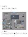
1
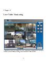
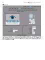
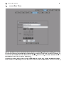
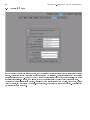
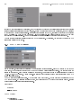
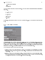
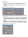
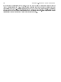
Digital Video Server
User Guide
Version 3.0
by Dividia Technologies, L.L.C.
01/05/2009
2
3
DISCLAIMER
No warranty or representation, either expressed or implied, is made with respect to the contents of this documentation, its
quality, performance, merchantability, or tness for a particular purpose. Information presented in this documentation
has been carefully checked for reliability; however, no responsibilities are assumed for inaccuracies.
The information
contained in this documentation is subject to change without notice.
In no event will Dividia Technologies be liable for direct, indirect, special, incidental, or consequential damages arising
out of the use or inability to use this product or documentation, even if advised of the possibility of such damages.
COPYRIGHT
2002-2009 by Dividia Technologies, L.L.C. All rights reserved. No part of this publication may be reproduced, transmitted,
transcribed, stored in a retrieval system, or translated into any language in any form by any means without the written
permission of Dividia Technologies, L.L.C.
4
Contents
1 Preface
7
1.1
Package Contents . . . . . . . . . . . . . . . . . . . . . . . . . . . . . . . . . . . . . . . . . . . . . . . . . .
7
1.2
Specications . . . . . . . . . . . . . . . . . . . . . . . . . . . . . . . . . . . . . . . . . . . . . . . . . . . .
8
1.3
Limited Warranty
. . . . . . . . . . . . . . . . . . . . . . . . . . . . . . . . . . . . . . . . . . . . . . . . .
8
1.3.1
Warranty Length . . . . . . . . . . . . . . . . . . . . . . . . . . . . . . . . . . . . . . . . . . . . . .
8
1.3.2
Who is protected?
. . . . . . . . . . . . . . . . . . . . . . . . . . . . . . . . . . . . . . . . . . . . .
8
1.3.3
What is and is not covered? . . . . . . . . . . . . . . . . . . . . . . . . . . . . . . . . . . . . . . . .
8
1.3.4
What we will and will not pay for? . . . . . . . . . . . . . . . . . . . . . . . . . . . . . . . . . . . .
9
1.3.5
Contact Information . . . . . . . . . . . . . . . . . . . . . . . . . . . . . . . . . . . . . . . . . . . .
9
2 DVS Introduction
11
3 Live Video Monitoring
13
3.1
1 - Camera Display . . . . . . . . . . . . . . . . . . . . . . . . . . . . . . . . . . . . . . . . . . . . . . . . .
14
3.2
4 - Camera Split Display . . . . . . . . . . . . . . . . . . . . . . . . . . . . . . . . . . . . . . . . . . . . . .
14
3.3
8 - Camera Split Display . . . . . . . . . . . . . . . . . . . . . . . . . . . . . . . . . . . . . . . . . . . . . .
14
3.4
9 - Camera Split Display . . . . . . . . . . . . . . . . . . . . . . . . . . . . . . . . . . . . . . . . . . . . . .
14
3.5
16 - Camera Split Display . . . . . . . . . . . . . . . . . . . . . . . . . . . . . . . . . . . . . . . . . . . . .
15
3.6
Full Screen Display . . . . . . . . . . . . . . . . . . . . . . . . . . . . . . . . . . . . . . . . . . . . . . . . .
15
3.7
Auto Scan . . . . . . . . . . . . . . . . . . . . . . . . . . . . . . . . . . . . . . . . . . . . . . . . . . . . . .
15
4 Playback of Recorded Video
4.1
Overview
4.2
Video Preview
4.3
Video Player
17
. . . . . . . . . . . . . . . . . . . . . . . . . . . . . . . . . . . . . . . . . . . . . . . . . . . . . .
. . . . . . . . . . . . . . . . . . . . . . . . . . . . . . . . . . . . . . . . . . . . . . . . . . .
18
. . . . . . . . . . . . . . . . . . . . . . . . . . . . . . . . . . . . . . . . . . . . . . . . . . . .
18
5 Setting up your DVS System
5.1
17
19
System Setup . . . . . . . . . . . . . . . . . . . . . . . . . . . . . . . . . . . . . . . . . . . . . . . . . . . .
20
5.1.1
DVR Name . . . . . . . . . . . . . . . . . . . . . . . . . . . . . . . . . . . . . . . . . . . . . . . . .
20
5.1.2
Recording Frame Rate . . . . . . . . . . . . . . . . . . . . . . . . . . . . . . . . . . . . . . . . . . .
20
5.1.3
Auto Scan Interval . . . . . . . . . . . . . . . . . . . . . . . . . . . . . . . . . . . . . . . . . . . . .
20
5.1.4
Email Setup . . . . . . . . . . . . . . . . . . . . . . . . . . . . . . . . . . . . . . . . . . . . . . . . .
21
5
CONTENTS
6
5.1.5
Digital Output (Optional) . . . . . . . . . . . . . . . . . . . . . . . . . . . . . . . . . . . . . . . . .
21
5.2
Device Setup
. . . . . . . . . . . . . . . . . . . . . . . . . . . . . . . . . . . . . . . . . . . . . . . . . . . .
22
5.3
Users Setup . . . . . . . . . . . . . . . . . . . . . . . . . . . . . . . . . . . . . . . . . . . . . . . . . . . . .
23
5.3.1
Overview
23
5.3.2
Setup a New User
. . . . . . . . . . . . . . . . . . . . . . . . . . . . . . . . . . . . . . . . . . . . .
23
5.3.3
Setup a New User by Copying an existing User . . . . . . . . . . . . . . . . . . . . . . . . . . . . .
23
5.3.4
Edit User Access Rights . . . . . . . . . . . . . . . . . . . . . . . . . . . . . . . . . . . . . . . . . .
24
5.3.5
Delete a User from the system
. . . . . . . . . . . . . . . . . . . . . . . . . . . . . . . . . . . . . .
24
5.3.6
Applying Changes for a user
. . . . . . . . . . . . . . . . . . . . . . . . . . . . . . . . . . . . . . .
24
Camera Setup . . . . . . . . . . . . . . . . . . . . . . . . . . . . . . . . . . . . . . . . . . . . . . . . . . . .
25
5.4.1
General
. . . . . . . . . . . . . . . . . . . . . . . . . . . . . . . . . . . . . . . . . . . . . . . . . . .
25
5.4.2
Video
. . . . . . . . . . . . . . . . . . . . . . . . . . . . . . . . . . . . . . . . . . . . . . . . . . . .
26
5.4.3
PTZ . . . . . . . . . . . . . . . . . . . . . . . . . . . . . . . . . . . . . . . . . . . . . . . . . . . . .
28
5.5
Date/Time Setup . . . . . . . . . . . . . . . . . . . . . . . . . . . . . . . . . . . . . . . . . . . . . . . . . .
29
5.6
Network Setup
. . . . . . . . . . . . . . . . . . . . . . . . . . . . . . . . . . . . . . . . . . . . . . . . . . .
30
5.7
Report . . . . . . . . . . . . . . . . . . . . . . . . . . . . . . . . . . . . . . . . . . . . . . . . . . . . . . . .
31
5.7.1
Summary
31
5.7.2
Camera Activity
. . . . . . . . . . . . . . . . . . . . . . . . . . . . . . . . . . . . . . . . . . . . . .
32
5.7.3
Alarm (Optional) . . . . . . . . . . . . . . . . . . . . . . . . . . . . . . . . . . . . . . . . . . . . . .
33
5.7.4
POS Reports
. . . . . . . . . . . . . . . . . . . . . . . . . . . . . . . . . . . . . . . . . . . . . . . .
34
POS (Optional) . . . . . . . . . . . . . . . . . . . . . . . . . . . . . . . . . . . . . . . . . . . . . . . . . . .
35
5.8.1
JWS / Apex (Optional) . . . . . . . . . . . . . . . . . . . . . . . . . . . . . . . . . . . . . . . . . .
36
5.8.2
Valve Sensing (Optional)
. . . . . . . . . . . . . . . . . . . . . . . . . . . . . . . . . . . . . . . . .
37
5.8.3
Scale Sensing (Optional) . . . . . . . . . . . . . . . . . . . . . . . . . . . . . . . . . . . . . . . . . .
38
5.8.4
PTZ Control Conguration (Optional) . . . . . . . . . . . . . . . . . . . . . . . . . . . . . . . . . .
39
5.8.5
Digital Output Conguration (Optional) . . . . . . . . . . . . . . . . . . . . . . . . . . . . . . . . .
39
5.4
5.8
. . . . . . . . . . . . . . . . . . . . . . . . . . . . . . . . . . . . . . . . . . . . . . . . . .
. . . . . . . . . . . . . . . . . . . . . . . . . . . . . . . . . . . . . . . . . . . . . . . . . .
6 Utilities
41
6.1
Export . . . . . . . . . . . . . . . . . . . . . . . . . . . . . . . . . . . . . . . . . . . . . . . . . . . . . . . .
41
6.2
Report . . . . . . . . . . . . . . . . . . . . . . . . . . . . . . . . . . . . . . . . . . . . . . . . . . . . . . . .
42
6.3
JWS Ticket Searching (Optional) . . . . . . . . . . . . . . . . . . . . . . . . . . . . . . . . . . . . . . . . .
43
6.4
Support
43
. . . . . . . . . . . . . . . . . . . . . . . . . . . . . . . . . . . . . . . . . . . . . . . . . . . . . . .
7 Remote Access
45
Chapter 1
Preface
Dividia Technologies Digital Video Server (DVS) is the latest in digital surveillance technology. It enables you to more
easily manage and catalog your video information. Your DVS implements the latest in Motion Detection technology.
When activity is detected, it automatically catalogs this information for easy access at a later time. The system will
automatically alert you to the events you are interested in. You no longer need to wade through hours of video to nd
the information you need.
1.1 Package Contents
Dividia Technologies DVS package includes:
•
DVS (Digital Video Server)
•
Power Cable
•
Keyboard and Mouse
•
BNC Breakout Cable(s)
7
CHAPTER 1.
8
PREFACE
1.2 Specications
Features
Standard HDD
250GB - 750GB
Maximum HDD
2TB
Minimum Storage
15 Days
Raid Mirroring
Optional
External Storage
DVD, HDD, USB
Video Compression
MPEG4
Resolution
320 X 240, 640 X 480
Recording Modes
Motion, 24/7
FPS per Camera
1 - 30
Display Modes
1, 4, 8, 9, or 16
Search Modes
Time/Date and text (only w/ POS Interface)
PTZ Support
Yes
Network Capability
Yes
Export Video
Yes
Field Upgradeable
Yes
Operating System
Linux
Video System
NTSC
Video Inputs
BNC
Video Outputs
VGA
Supported Cameras
CCTV, TCP, IP
Dimensions
16.7 X 6.3 X 16
Weight
23.5lbs
AC Power Input
115/230V
1.3 Limited Warranty
Dividia Technologies, L.L.C. warrants that this product to be free of defects resulting from faulty manufacturing or
components under the following terms:
1.3.1 Warranty Length
Labor is warranted for 12 months from the date of purchase.
Replacement products will be warranted for 12 months from the date of purchase.
All warranted items must be shipped to Dividia Technologies, L.L.C. for work to be completed unless otherwise stated.
1.3.2 Who is protected?
This warranty is enforceable only by the rst consumer purchaser.
1.3.3 What is and is not covered?
Except as specied below, this warranty covers all defects resulting from faulty manufacturing of this product.
following are not covered by the warranty.
1. Any product on which the serial number has been defaced, modied, or removed.
2. Damage, deterioration, or malfunction resulting from:
The
1.3. LIMITED WARRANTY
•
9
Accident, abuse, misuse, neglect, re, water, lightning, or other acts of nature, unauthorized product modication, or failure to follow instructions included with the product.
•
Misapplication of service by someone other than the manufacturer's representative.
•
Any shipment damages. (Claims must be made with carriers)
•
Any other cause that does not relate to a product defect.
3. Cartons, cases, batteries, cabinets, tapes, or accessories used with the product.
4. Dividia Technologies, L.L.C. does not warrant that this product will meet your requirements; it is your responsibility
to determine the suitability of this product for your purpose.
1.3.4 What we will and will not pay for?
We will pay labor and material expenses for covered items. However, we will not pay for the following:
1. Removal or installation charges
2. Shipping charges
3. Any incidental charges
1.3.5 Contact Information
2901 Alta Mere Dr, Suite 800
Fort Worth, TX 76116
TEL: 866-348-4342
FAX: 817-288-1039
WEB: www.dividia.net
10
CHAPTER 1.
PREFACE
Chapter 2
DVS Introduction
Once everything is connected properly, press the power button located on the front of the DVS system. This will begin
the boot-up process. Once the system completes the self-test and normal boot-up procedure, you are presented with a
login screen. Before you can begin to use your new DVS, you must rst login. This keeps unauthorized persons from
accessing your video information.
There are varying levels of access to your DVS system. By default, the admin account has access to all features of the
system. To start using your system, please login with the default information:
Username
Password
admin
admin
11
12
CHAPTER 2.
DVS INTRODUCTION
Chapter 3
Live Video Monitoring
After logging into the system, you are presented with the Live Monitoring screen. This screen allows you to view all your
cameras in varying congurations on the screen. There are 5 split display modes to choose from:
13
CHAPTER 3.
14
LIVE VIDEO MONITORING
1 - Camera Display
4 - Camera Split Display
8 - Camera Split Display
9 - Camera Split Display
16 - Camera Split Display
3.1 1 - Camera Display
In this display, you are able to monitor a single camera at a time. While in this display, you will be presented with a
button for each camera 1-16 to choose from. By clicking on one of these buttons, that camera will be displayed.
3.2 4 - Camera Split Display
In this display, you are able to view 4 cameras at a time. The groups of cameras displayed will be 1-4, 5-8, 9-12, and
13-16 depending on the number of cameras supported by your DVS. If all the cameras for a particular group have been
disabled, then that button will be inactive. You will not be able to click on an inactive button.
If you would like to view one of the cameras in the display in full view, then double click on that camera. When you
would like to return to the split display, double click on the camera's video. This will return you to your split display.
3.3 8 - Camera Split Display
In this display, you are able to view 8 cameras at a time. This display is only available on systems supporting 8 or more
cameras. The groups of cameras displayed will be 1-8 and 9-16 depending on the number of cameras supported by your
DVS. If all the cameras for a particular group have been disabled, then that button will be inactive. You will not be able
to click on an inactive button.
This display is very eective when monitoring several areas at one time. You are able to double click on any camera's
video to move that camera to the large display area. However, the other 7 cameras remain visible for monitoring at the
same time. This way, you are able to continue monitoring all cameras while reviewing a certain camera.
3.4 9 - Camera Split Display
In this display, you are able to view 9 cameras at a time. This display is only available on systems supporting 9 or more
cameras. The groups of cameras displayed will be 1-9 and 8-16 depending on the number of cameras supported by your
DVS. If all cameras for a particular group have been disabled, then that button will be inactive. You will not be able to
click on an inactive button.
If you would like to view one of the cameras in the display in full view, then double click on that camera. When you
would like to return to the split display, double click on the camera's video. This will return you to your split display.
3.5. 16 - CAMERA SPLIT DISPLAY
15
3.5 16 - Camera Split Display
In this display, you are able to view 16 cameras at a time.
This display is only available on systems supporting 16
cameras. The group of cameras displayed will be 1-16.
If you would like to view one of the cameras in the display in full view, then double click on that camera. When you
would like to return to the split display, double click on the camera's video. This will return you to your split display.
3.6 Full Screen Display
From this screen, you are also able to monitor your cameras in full screen. This makes the camera viewing area take all
the available space on the screen. You are still able to move from single to split display while in full screen mode.
To exit the full screen display, right click anywhere on the screen.
3.7 Auto Scan
In each of the above mentioned camera displays, you are able to turn on auto scan. Auto Scan allows you to scan through
each of the camera groups continuously. For instance, if you are in 1 Camera Display, Auto Scan will move from Camera
1 to Camera 2, etc. The Auto Scan interval defaults to 10 seconds; however, this interval can be congured through
system setup. Click on any camera group to exit Auto Scan.
16
CHAPTER 3.
LIVE VIDEO MONITORING
Chapter 4
Playback of Recorded Video
4.1 Overview
The playback screen allows you to access all recorded video. You are able to retrieve recorded video by Date and Time.
Additionally, you can apply various Filters to the search. Each lter, limits the amount of video you have to review to
nd the video you are looking for. You can view video using the following procedure:
17
CHAPTER 4.
18
PLAYBACK OF RECORDED VIDEO
1. Select a camera to view.
2. Select any Filters you wish to have applied to the search.
3. Select a Date and Time.
4. Click the Find button.
If no video was found for that camera, then you will receive a prompt notifying you that there is nothing to review.
Otherwise, your desired video will start playing automatically.
4.2 Video Preview
The video review area consists of two sections. On the left will be the video preview area. This area contains snapshots
of the activity that occurred around your desired time. Click on a preview snapshot to begin playing that segment of
video. The video will begin to play in the player section of the video review area.
If the video you are looking for is not located in the preview area, you can click the Next or Previous buttons to load
another set of 9 previews. In this, you are able to quickly step through all recorded video for this camera. For instance,
you may be looking for the time a car left your parking lot. You could easily scan through hours of video to determine
when the car left, all without the need to watch video.
4.3 Video Player
From the player section, you are able to control the video with VCR like controls. You can Play, Pause, Stop, Rewind,
and Fast Forward the video. If you would like to see more detail, you can click the Full Screen button. While in the Full
Screen view, only the player is visible. This allows for an optimum viewing experience. When you are ready to leave Full
Screen, just click the Full Screen button again to exit this display.
Chapter 5
Setting up your DVS System
From the Setup screen, you are able to change how your DVS system operates. You are able to Setup the following:
1. System
This section contains basic system settings such as Auto Scan Interval, UPS support, etc.
2. Device
This seciton allows you to add camera input devices (Capture Cards, Moxa's, Network Cameras, etc).
3. Users
This section allows you to add and remove users from the system. You can also change access rights.
4. Cameras
This section allows you to adjust camera settings, such as Name, Brightness, etc.
5. Date/Time
This section allows you to adjust the Date and Time settings of your DVS.
6. Network
This section allows you to adjust your networks settings, such as DHCP, Static, DNS, etc.
7. Report
This section allows you to create various reports, such as Summary (Event Totals, etc), Camera Activity, etc.
8. POS
This section allows you to setup interfaces between your DVS system and various POS systems.
support is sold separately.
19
POS System
20
CHAPTER 5.
SETTING UP YOUR DVS SYSTEM
5.1 System Setup
5.1.1 DVR Name
You have the ability to name your DVS. You should pick a name that uniquely describes the system. Oftentimes, this
may be the physical location. This name can be 32 alphanumeric characters in length.
5.1.2 Recording Frame Rate
You are able to adjust the recording frame rate for each of the cameras independently. If you would like to set all the
cameras to the same recording frame rate, just select the All Check Box. Now you can adjust any one camera and the
others will follow. The recommended setting is from 2-5 fps. The higher you set the fps, the more storage your video
will occupy. This means that higher settings allow you to record less days.
You can also congure how many seconds before and after the triggering motion you would like to record. You can only
record a maximum of 2 seconds before the triggered motion. This is useful to see what was going on just before the
activity occurred. Recording extra time after the event is useful to maintain continuity throughout multiple events.
5.1.3 Auto Scan Interval
Auto Scan allows you to continuously scan through your cameras under the Live Monitoring Display. This is the interval
to wait before switching cameras. For instance, this interval is set to 10 seconds and you are in 4 Camera Split Display.
5.1. SYSTEM SETUP
21
Initially, cameras 1-4 would be displayed on the screen. After a period of 10 seconds, those cameras would switch to
5-8. After another 10 seconds, those cameras would switch to 9-12. This would continue indenitely or until you select
another Display or camera group.
5.1.4 Email Setup
There are certain times when the system might want to send an email for notication. Various reports that you will
learn about in a later section will utilize this setting. In order for the emails to be sent properly, you must rst tell it
how to send them. You can congure which server to send it through and with what user credentials.
5.1.5 Digital Output (Optional)
If you purchased the Digital Input/Output Module, then you now have the option of activating certain digital output
relays. This will output 12V on whichever outputs you suggest. So, if you wanted to drive a pair of dry contacts, this
would allow you to do so. Before using this option, you have to select which Camera input Device these digital inputs
and outputs are associated with.
22
CHAPTER 5.
SETTING UP YOUR DVS SYSTEM
5.2 Device Setup
In order to record from a camera, you must have at least one input device congured on your DVS. An input device
could be a PCI Capture Card as depicted in the picture above. It could also be a Network Device or Network Camera.
In order to add a new input Device, you have to give it an unique name. Then specify all the options at the bottom
of the screen (Type, IP, Username, and Password). The elds IP, Username, and Password are only used if this is a
network attached device.
5.3. USERS SETUP
23
5.3 Users Setup
5.3.1 Overview
From this screen, you are able to manage all access to your Digital Video System. You can create/edit/delete users. You
can change what access rights each user has to your system.
5.3.2 Setup a New User
To create a new user, click on the New button.
A prompt will appear asking for various user information.
Enter a
Username into the appropriate eld. Keep in mind that your username and password settings are case-sensitive. Make
a note if you are entering them with the CAPS lock enabled or mix-case lettering. After entering your username, type
the password you wish to setup. Type it a second time in the Conrm Password box. If the passwords do not match,
you will be required to re-enter this information. Once you are nished, click the OK button.
5.3.3 Setup a New User by Copying an existing User
You are able to create a new user with the exact same rights as another user on the system. Select the user you would
like to copy in the User List. Click the Copy button. It will prompt you asking for various user information. Enter a
Username into the appropriate eld for the user you would like to create. The username and password settings are the
same for create New Users.
CHAPTER 5.
24
SETTING UP YOUR DVS SYSTEM
5.3.4 Edit User Access Rights
After your new user has been created, it will be selected in the list of users on the screen. You will want to setup what
this user can do on the system. You do this by assigning Server Rights to the user. These rights give you a ne-grained
ability to extend or limit access to your system. Below is a description of each right. Additionally, you will want to select
which cameras this user is able to access.
Server Rights
•
Access
The access right determines whether this user will have any access to this system. If this box is not checked, then
the user will not be able to login. This is useful if you would like to temporarily disable a users account without
deleting it.
•
Administrator
The admin right enables special Administrator features on the system. A user that has the Admin right is able to
control all aspects of the Setup Screen including System, Users, Camera, Date/Time, and Network. They are also
able to access the Utilities and Playback sections.
•
Export
The export right allows the user to use the Utilities->Export screen. From this screen, they will be able to export
video o the system. If you do not wish for users to take video o-site, you should disable this right.
•
Remote Viewing
The remote viewing right allows the user to view the cameras through a web-browser. Without this right, they will
get an access denied message.
•
PTZ Control
Can this user control any attached Pan/Tilt/Zoom cameras?
5.3.5 Delete a User from the system
To delete a user, select the username in the User List on the screen. Next, click the Delete button. You will be prompted
to make sure you would like to delete the user. If you do, click the OK button. If this was a mistake and you do not
want to delete the user, click the Cancel button.
5.3.6 Applying Changes for a user
When you are nished making changes to a user, do not forget to apply those changes by clicking the Apply button. If
you forget to click the Apply button, the system will prompt you to make sure you do not intend to lose your changes.
5.4. CAMERA SETUP
25
5.4 Camera Setup
This section allows you to customize all the per-camera settings. To select each camera in turn, click on the corresponding
Camera number. This will load the various settings for this camera. For each camera, there are three tabs full of settings:
General, Video, and PTZ.
5.4.1 General
If you do not have a camera attached to this position, it is best to disable the camera.
You can disable the camera
by un-checking the Enable check box. This will completely turn o this camera preventing it from using any system
resources.
If you would like to give each camera a unique name, you can enter it into the Camera name eld. Please be sure to only
use alphanumeric characters. There is a maximum of 32 characters for each camera name.
Next, select which Camera input Device you would like to use for this camera. Your DVS system supports 2 types of
cameras. CCTV cameras are standard CCD cameras that plug into the back of your system via Coaxial BNC connection.
Network cameras are network oriented cameras that run over a standard Ethernet network and are IP addressable. We
currently support a select number of Network cameras.
contact Customer Support.
If you have a question regarding a particular camera, please
26
CHAPTER 5.
SETTING UP YOUR DVS SYSTEM
5.4.2 Video
Preview
If you would like to see a live preview of your camera as you are making changes, click the Preview check box. Any
changes you make that aect how the camera looks (brightness, etc) can be viewed in real-time.
Mask
When you click the Mask button, you will see a grid displayed on top of the video. By clicking on a segment of the grid,
it will turn black. Each black box indicates areas where the recorder will ignore activity. That area will still show up on
the recorded video, but any activity that occurs in those areas will not trigger recording.
Activity
When you click the Activity button, a black/white video that mimics the live preview shot will begin to play. This is
similar to what the computer sees as activity. The counters on the screen indicate how many pixels are changing on
the screen. You can adjust this sensitivity setting below in the recording settings.
5.4. CAMERA SETUP
27
Brightness and Recording Settings
If your cameras appear too dark or light, you have the ability to adjust the Brightness, Contrast, Saturation, and Hue.
You can change the recording resolution for a sepcic camera. The default resolution is 320x240. You can increase this
to 640x480. Please remember that these settings will directly impact the performance of your system. This will include
frame rate, quality, and days of storage.
To change how your cameras behave when detecting motion activity on a camera, change the Record Type. The following
options are explained:
•
On
This will disable any motion detection and always record, 24/7, for this camera.
•
O
This will disable any motion detection and never record. However, the camera will still be available for live viewing.
•
Motion
This will utilize state-of-the-art motion detection algorithms to eliminate hours of useless video. With this setting
enabled, no video will be recorded unless there is activity in front of the camera. This allows you to eectively use
your time by jumping directly to incidents of importance.
•
Alarm
This setting allows you to hook a physical relay into your video system. For instance, if you would like to only
record when a door is opened, you would use this feature.
The motion sensitivity setting determines at what point the DVS system will start recording when there is activity. If
you are recording too much, then increase this setting. This will make it so that more activity will be needed to start
recording.
Despeckle is useful if your camera is very grainy at night. You can turn on despeckle and it will attempt to ignore the
small pixel changes caused by Auto Gain Control in low light situations.
Smartmask is useful to automatically tune your mask les for constantly slow moving objects like trees blowing in the
wind.
You can also adjust the quality of recorded video per camera. The lower the number (default 2) the better the recorded
quality. If you would like to save some space, you can turn this setting up. Valid values are 1-31.
28
CHAPTER 5.
SETTING UP YOUR DVS SYSTEM
5.4.3 PTZ
Pan/Tilt/Zoom cameras allow you to control the camera remotely. If this camera is a PTZ camera, check the Enable
box. We currently support Pelco PTZ cameras directly, or almost all PTZ cameras through our Moxa Vport. Select the
protocol that corresponds to your camera brand/model. If this PTZ is connected through a serial port, be sure to select
the appropriate serial port settings.
5.5. DATE/TIME SETUP
29
5.5 Date/Time Setup
It is very important that you have the correct date and time set on your system. If this is not set correctly, then you will
have diculty nding the video information you are looking for. There are two ways to set the time on your system. If
the Sync time automatically with a time server check box is checked, then every hour, your system will contact the time
server listed in the text box to obtain the current time.
The second way is to un-check the check box and manually select the date and time. This is most useful if your system
is not connected to the Internet, or you would like to sync the time manually to another system such as a POS system.
30
CHAPTER 5.
SETTING UP YOUR DVS SYSTEM
5.6 Network Setup
If you would like to access your system remotely, then you will need to enter the correct network settings for your local
network. This information can be obtained for your local System Administrator. The default setting is to Automatically
obtain IP settings with DHCP. If you have a DHCP server on your local network that hands out addresses, then this is
the easiest conguration. However, you will need to know the address before you will be able to connect remotely.
The second way is to Statically set IP address. This allows you to manually specify the IP Address, Subnet Mask, Default
Gateway Address, and the Primary DNS Server. Once completed, do not forget to click the Save button. This will apply
any changes that have been made.
5.7. REPORT
31
5.7 Report
Your DVS system supports a number of dierent reports.
Reports contain information about your DVS system.
By
default, DVS systems contain a summary report that will provide you with event totals. Additionally, you can congure
Camera Activity reports.
If you purchased any of the optional POS Modules, then you will have an additional POS
Reports tab as well. All of these reports can be scheduled. The camera activity report will only report on activity if it
is within the dened schedule. You can specify up to 3 dierent email addresses that will be emailed for each report.
5.7.1 Summary
This is an email only report. It will not store any photos or video locally on the system. The schedule you specify is
not a range. It is the exact time you would like the report to run and be emailed. You can report totals or detailed
statistics. The detail will contain line items for each event matching your selected option. There are three main pieces
of information available for this report.
1. Event Total/Detail
This will show you the number of events broken down by camera that your system recorded. Each time a camera
senses activity it will log an event. If you choose to see the detail, it will tell you which camera, what time, how
long an event lasted.
2. Report Total/Detail
This will show you the number of reports that were generated from the POS Module. For instance, you can view
a detailed list of which Scale Reports were generated and what information was contained on them (tare weight,
etc).
CHAPTER 5.
32
SETTING UP YOUR DVS SYSTEM
3. Ticket Total/Detail
This will show you the number of tickets captured from your Apex system if you purchased the POS Module and
are using the JWS/Apex type.
5.7.2 Camera Activity
This is an email only report. It will not store any photos or video locally on the system. This report will notify you
when there is activity on a certain camera. The default schedule for this report is everyday all the time.
5.7. REPORT
33
5.7.3 Alarm (Optional)
If you purchased the Digital Input Output Model, then you will have access to alarm reports.
You can setup these
reports to trigger based on a change in one of the digital input lines. This is very useful for wiring your DVS system to
an Alarm and force a snapshot when a zone trips.
CHAPTER 5.
34
SETTING UP YOUR DVS SYSTEM
5.7.4 POS Reports
This screen will let you congure how you want all of your POS reports to behave.
If you do not have any reports
congured on this screen, then your Valve/Scale reports will not do anything. You can setup multiple reports to report
on the same thing but you may have dierent schedules, or notify dierent email address during dierent time periods.
Below is a description of each report.
•
Valve Timeout
If you have the Valve Sensing Conguration enabled, then if the valve opened and closed and we never received a
ticket, a Valve Timeout report is generated. It will contain the photos of the truck as it was getting lled.
•
Lost Connection with Scale
If your DVS is not able to communicate with the scale, then this report will get generated.
•
Restored Connection with Scale
Upon successfully reconnecting with a scale after a
Lost Connection with Scale
is generated, this report will be
generated to notify you of the change.
•
Tare Weight Contamination
As the scale starts to increase from 0 (zero) weight, your DVS will monitor it. Once the scale settles for the rst
time, we record this as the Tare weight. If this weight is above your precongured threshold, then this report will
be generated. It will tell you what your threshold is and what the actual Tare weight reading was.
•
No Ticket
If a truck was on the scale and drives o, but your DVS never received a ticket from the Apex system, then a No
5.8. POS (OPTIONAL)
Ticket report is generated. If we generated a
35
Tare Weight Contamination report, then we will skip this report so
you don't get a false alarm if you told the truck to go unload the old product.
•
Gross Ticket Weight Mismatch
Once a ticket is generated, we will compare the weight on the ticket with our maximum weight reading on the scale.
If those weights dier by more than your precongured threshold, then this report is generated.
•
Overweight Truck
Your DVS system will monitor the scale weight as you are lling the product. If the maximum weight on the scale
goes above your overweight threshold, we will generate an overweight report.
5.8 POS (Optional)
From here you can congure various POS systems with Text Overlay. Select the supported POS type from the POS drop
down menu.
CHAPTER 5.
36
SETTING UP YOUR DVS SYSTEM
If this POS supports Serial communication, then you will need to congure the Serial Settings section which contains
standard Serial port settings such as baud rate, etc. If this POS supports Network communication, then you will need
to congure the Network Settings section. For network conguration of the DVS, just select which port you would like
the DVS to listen on. Then, on your POS system, set up a generic text-only driver to print to the DVS IP and port
combination you have established. Your DVS will overlay any information sent to this port over the network.
You can choose to associate several cameras with a POS transaction. Additionally, you can elect to overlay the POS
information directly on the image.
5.8.1 JWS / Apex (Optional)
For JWS systems, there will be additional JWS Conguration options available.
Since JWS tickets do not take up
much space, you can specify a ticket count to keep on the system before erasing old tickets.
tickets on the network.
You can also share the
From another machine on the network, you should be able to access this share by going to
//IP.OF.DVS.SYSTEM/tickets.
This is a read-only directory that contains the same ticket information as the DVS
system has in its catalog.
Two JWS ticket formats are supported. The old option has a xed format. You can use this by unselecting the New
XML Format button. By selecting that same button, you will use the new XML format that is recommended. It is far
more exible and allows for ner grained searching.
Fixed Format
Plant *8
...
Ticket No *10
New XML Format
<ticketentry>
<ticket>*10</ticket>
5.8. POS (OPTIONAL)
37
<uniqueid>*757</uniqueid>
...
</ticketentry>
You can now specify a File Format to save the tickets in. You can use a variety of variable placeholders to insert relevant
information.
•
%k - Ticket Number
•
%u - Unique ID
•
%r - Reprint ID
•
%i - Scale ID
Additionally, you can specify 02 to zero pad a number by a certain amount. So, D%04r would produce D0001 for Reprint
ID 1.
5.8.2 Valve Sensing (Optional)
Valve Sensing allows your DVS system to communicate directly with the PLC that controls the valve. You can have a
dry contact connected to your DVS that provides a low-voltage signal +12V to the DVS when the valve is either open or
closed. As soon as the valve opens, we will take pictures of the truck on the scale. If we have not received a ticket from
the Apex system before a timer expires, then we will generate a Valve Alert and save the previously generated pictures
associated with this Report. The le format is similar to that of the Apex conguration above.
You can congure the timer to behave in one of two ways.
1. Initiate the timer when the valve closes for the rst time.
This is useful in Cement installations where loading
happens in one place. In other words, the truck never moves. The default timeout of 120 seconds should suce in
this scenario.
2. Initiate the timer when the truck leaves the scale.
This option requires that you have Scale Sensing properly
congured. This is useful in Asphalt installations where the loading happens on one scale but several dierent silos.
Obviously, the timer should be much shorter ( 0-10 seconds) in this scenario.
CHAPTER 5.
38
SETTING UP YOUR DVS SYSTEM
5.8.3 Scale Sensing (Optional)
Scale Sensing is similar to Valve Sensing. However, with this, we do not interface with the PLC, but talk directly to
the Scale just as your Apex system does. Select the type of scale indicator you will be using on this scale. Your scale
indicator should be networkable. If it is not, then contact our Sales Department and they will instruct you on how to
convert a traditional indicator into a networkable one. Once you have conrmed that the scale indicator is accessible via
TCP/IP (the network), please enter the IP address and TCP Port that it can be accessed on. Below is a listing of the
rest of the settings on this screen. These are criteria used while monitoring the scale output to decide if and when to
generate reports based on this information.
•
Tare Minimum
This is the minimum weight that we will use for a tare weight. This should be set high enough so anything smaller
than a truck is not detected on the scale
•
Tare Maximum
What is the maximum empty weight we should read on the scale? Anything over this threshold will generate a
possible Tare Contamination Report. We want to make sure that the trucks are empty before we add our product
in to make sure we are not mixing our product with the product from another company.
•
Weight Decrease Limit
When lling a truck on the scale, sometimes the weight will bounce up and down by small amounts 20-40 pounds.
By what amount of weight decrease on the scale should we consider the truck leaving the scale? The default settings
is 1000 pounds.
•
Ticket Weight Dierent Limit
What is the maximum weight dierence between the maximum weight we read from the scale and the gross weight
eld on the ticket? These weights may not always match since the driver may get out of the vehicle. The default
is 500 pounds.
•
Maximum Weight Limit
If your state regulates a maximum allowable weight through D.O.T. the you can add a limit here. Any truck loaded
above this threshold will generate an Overweight Report.
5.8. POS (OPTIONAL)
•
39
Ticket Weight Field
In your Apex XML template, what is the name of the eld that contains the gross weight? The value of this eld
will be used to compare the maximum weight we saw on the scale. The weight should be in pounds.
•
File Format
In what format should we save our le. You may use the special variable %u to insert the unique ID associated
with this report.
5.8.4 PTZ Control Conguration (Optional)
If you purchased a PTZ (Pan/Tilt/Zoom) camera, you can control it based on certain input from your Apex system.
There are two dierent ways you can set this up depending on if you purchased the Digital Input/Output Module.
1. Template Field
You can enter a eld that is contained on your Apex XML template. Then when Apex prints a ticket and sends
it to your DVS, we will parse the value for that eld and tell your PTZ to go to that preset.
For example, if
you specify Silo, like the screenshot above, and on your ticket we see <silo>Silo 1</silo>, then we will tell
PTZ (CAM 10) to jump to preset Silo 1. This option does not require the addition of the Digital Input/Output
Module.
2. Digital Input
Using this option, you can control a PTZ based on digital inputs. As you can see in the screenshot above, you tie
certain inputs to certain PTZ presets. A good example would be to wire some relays into your PLC that will send
us digital input based on which Silo gate is open. This is very handy for license plate shots on Asphalt facilities.
5.8.5 Digital Output Conguration (Optional)
40
CHAPTER 5.
SETTING UP YOUR DVS SYSTEM
If you purchased the digital input/output module, the you now have the ability to control other equipment based on
your DVS receiving tickets from Apex. An example of such a scenario would be if you wanted to control a trac light
automatically with your DVS. This setup requires the use of a Moxa VPort to wire everything into. In the screenshot
above you can see where you select which digital outputs you would like to tie to this scale. Next, you specify in which
conditions you want to open or close the relay associated with that digital output number. You can also specify a timeout
after receiving the ticket to revert such a change (change the light red again).
Chapter 6
Utilities
This section contains various utilities you might nd useful for your system. For example, through these utilities, you
will be able to export video from your system.
6.1 Export
To export video from your Digital Video System, you should rst decide what video you would like to export. You can
41
42
CHAPTER 6.
UTILITIES
do this by selecting the desired cameras to export. Second, you can export video between two dates and times. You can
also export any video you intentionally agged while reviewing the video through Playback.
Finally, select which device to export to, then click the OK button. When nished, you should have a new CD, DVD,
External Hard Drive, or Network Share containing video les. To playback the video, select a playlist for a camera.
6.2 Report
If your DVS system generates Reports that may save les (POS Style Reports), then you can search them here. You can
search by the type of report and a date/time that the report was generated. This will allow you to review the camera
shots associated with the report.
6.3. JWS TICKET SEARCHING (OPTIONAL)
43
6.3 JWS Ticket Searching (Optional)
You can search by JWS ticket numbers with this screen. Type in the ticket number you are looking for and click Find.
A preview of 9 tickets surrounding the ticket number you searched for will appear on the left side of the screen. To view
a particular ticket, click on that preview shot. The ticket will load in the right part of the screen.
You can associate several dierent cameras with a JWS ticket. If more than one camera is associated with the ticket,
they will be numbered sequentially above the image. Just click on the radio button for that camera to display various
shots of the ticket.
You are also able to zoom in on certain areas of the image. Just click and drag a box around any area that you would
like to see up closer. To return to your normal view, just click anywhere on the image.
6.4 Support
This section contains a number of technical support utilities. These are often used in diagnosing problems remotely when
speaking with Customer Support.
44
CHAPTER 6.
UTILITIES
Chapter 7
Remote Access
To access the system remotely, you must rst have the Remote Viewing right under the Setup -> Users screen. Once
that is set, you can access your DVS by simply opening a web-browser (Internet Explorer, Firefox, etc) and going to
http://IP.OF.DVS.SYSTEM/ and clicking Go.
option is the
You have two options to view your DVS system remotely.
The rst
Standard Viewer. This is a web-based HTML viewer that allows you to quickly view your DVS system live.
If you would like to playback recorded footage or access any of the conguration section of your DVS, you must run the
Advanced Viewer.
45