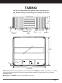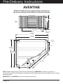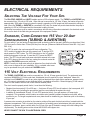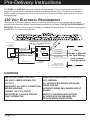
1
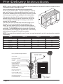
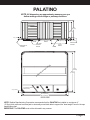
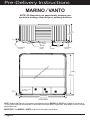
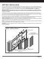
Vacanza® Series Pre-Delivery Instructions
Please take the time to read this booklet carefully, as it will provide you with the information you will need to ensure
the safe, secure, and timely installation of your new spa. The following sections are guidelines on how to prepare for
delivery and set-up of your new spa. Specifically covered are site selection, delivery access, ground preparation, and
electrical requirements.
Remember to carefully read the Owner’s Manual that accompanies your spa, and to complete the warranty card
within 10 days of delivery. These items, along with other valuable information, will be found in the Owner’s Package
which has been placed in the equipment compartment of your spa, where you will also find a serial number.
Watkins Manufacturing Corporation reserves the right to change features, specifications and design without
notification and without incurring any obligation.
DATE PURCHASED: __________________________________________________________________
DATE INSTALLED:____________________________________________________________________
DEALER:____________________________________________________________________________
ADDRESS:___________________________________________________________________________
TELEPHONE:________________________________________________________________________
In most cities and counties, permits will be required for the installation of electrical circuits or the construction of
exterior surfaces (decks and gazebos). In addition, some communities have adopted residential barrier codes which
may require fencing and/or self-closing gates on the property to prevent unsupervised access to a pool (or spa) by
children under 5 years of age. Your Caldera® spa is equipped with a locking cover that meets the ASTM F1346-91
Standard for Safety Covers and as a result, is usually exempt from most barrier requirements. As a general practice,
your local Building Department will inform you of any applicable barrier requirements at the time a permit is obtained
for the installation of an electrical circuit. Your CALDERA dealer can provide information on which permits may be
required.
Pre-Delivery Instructions
SITE SELECTION AND PREPARATION
IMPORTANT: Site selection and preparation are your responsibility. Carefully read these instructions and consult
your authorized CALDERA dealer if you have any questions.
You probably have a spot picked out for your new spa, whether it’s indoors or outdoors, on a patio or on a deck. Just
make sure you check the following:
• Always put your spa on a structurally sound, level surface. A filled spa can weigh a great deal. Make certain
that the location you choose can support the weight of your filled spa.
• Locate your equipment compartment, which houses all of the electrical components, in a place where water
will drain away from it. Allowing water into the equipment compartment can damage the electronics, or may
result in tripping your house’s circuit breaker.
• Leave yourself easy access to the circuit breakers in the subpanel.
• Never let water get into the subpanel (230 volt models) or into the GFCI by the end of the power cord
(115 volt models).
• Leave access to the entire front of the spa (the removable panel provides access to the spa’s equipment) for
periodic spa care and maintenance.
Indoor/Basement Installation
Be aware of some special requirements if you place your spa indoors. Water will accumulate around the spa, so
flooring materials must provide a good grip when wet. Proper drainage is essential to prevent a build-up of water
around the spa. When building a new room for the spa, it is recommended that a floor drain be installed. The
humidity will naturally increase with the spa installed. Water may get into woodwork and produce dryrot, mildew, or
other problems. Check for the effects of airborne moisture on exposed wood, paper, etc. in the room. To minimize
these effects, it is best to provide plenty of ventilation to the spa area. An architect can help to determine if more
ventilation must be installed.
Your CALDERA dealer can help you with local information such as zoning regulations and building codes.
Deck Installation
To be certain your deck can support your spa, you must know the deck’s maximum load capacity. Consult a
qualified building contractor or structural engineer before you place the spa on an elevated deck or indoors.
To find the weight of your spa, its contents and occupants, refer to the Spa Specification chart on back page. This
weight per square foot must not exceed the structure’s rated capacity, or serious structural damage could result.
Outdoor and Patio Installation
No matter where you install your new spa, it’s important that you have a solid foundation to support it. Structural
damage to the spa resulting from incorrect installation or placement on an inadequate foundation is not covered
under the spa’s limited warranty (See next page for specifics).
Page 2
Ground and Spa Leveling Preparation
Your CALDERA spa has been engineered to perform on several
types of common yard surfaces. While a concrete slab is best for
long-term use*, other foundations are acceptable so long as a level
base is prepared prior to delivery. Three foundation base pictures,
shown at right, represent examples of alternatives to a concrete slab
for spas installed without gazebos or other accessories.
*NOTE: A reinforced concrete pad at least four inches thick or
structurally sound deck able to support the “dead weight” (found in
the Spa Specification Chart on back page) is recommended for your
CALDERA spa. The reinforcing rod or mesh in the pad should be
attached to a bond wire.
FOUNDATIONS FOR SPAS ONLY
(No accessories such as cover or gazebo)
PEA GRAVEL
OR CRUSHED ROCK
RAILROAD TIES
INSTALLATION NOTES:
• Concrete sloped at 1/2 inch per 10 feet is preferred so that rain water and water spillover will run off and not puddle underneath the spa (water under the spa for long periods of time may cause the wood to deteriorate).
• If stepping stones or railroad ties are selected for the spa
foundation, they should be placed and leveled below the entire
spa to maintain even distribution of the spa weight.
• It is important to note that soft surfaces, even when stepping
stones are used to distribute the weight of the spa as evenly
as possible, will still have a tendency to settle unevenly,
resulting in an unlevel spa.
• Remember, placing the spa on grass or dirt may increase the
amount of debris which is inadvertently brought into the spa
water on the user’s feet.
If you are purchasing a deck package or gazebo with your spa,
a solid foundation becomes mandatory. Placing them on any
surface other than a single level pad could create problems with
their installation. Pictured at right are a few of the recommended
surfaces.
As a homeowner, it is your responsibility to provide a suitable, level
foundation for your spa. Keep in mind that most delivery crews are
not equipped to level and prepare spa sites.
If you are interested in having a concrete slab, brick surface, or
wood deck installed, your CALDERA dealer should be able to
suggest a qualified, licensed contractor.
PRE-CAST
STEPPING STONES
FOUNDATIONS FOR SPAS
WITH ACCESSORIES
(such as gazebo)
CONCRETE PADS
BRICK SURFACES
WOOD DECKING
Delivery Access
First, locate the dimensions of your spa on the chart on the next page. The dimensions shown are the
measurements of the spa in the vertical position, laid on its side.
Next, contact your dealer to find the height and width added by the delivery cart which the dealer will use to deliver
your new spa. Use the height of the cart plus the dimension shown as H to determine the vertical clearance required
to pass the spa and cart. Use the width of the cart, or dimension W, whichever is greater, to determine the maximum
width of clearance necessary.
Page 3
Pre-Delivery Instructions
NOTE: It may be necessary to allow for additional over-head clearance if the spa will be rolled up or down an incline
or moved up or down a short flight of stairs.
Use the information below to determine the requirements for
access to your desired location. It may be necessary to remove a
gate, part of a fence, or other movable obstructions in order to roll
the spa to its installation site. About ten percent of the time, a crane
is the only way to install the spa by lifting it to its final destination.
If the spa has to be taken off of the cart to go over a wall (either
because the entry area is too narrow, the eaves are too low, the
corner is too tight, or the stairway is too steep), a crane will be
required. Don’t be alarmed!
The crane has a truck-mounted boom which can fit right in your
driveway. It is run by a licensed and insured operator. For a
charge, the crane operator will lift your spa over walls, buildings,
or any other obstruction and place it as close to the installation site
as possible. The CALDERA spa delivery personnel will supervise
the crane delivery and complete the spa placement. Crane delivery
typically takes an average of 30 minutes to complete.
NOTE: If your spa delivery requires the use of a crane, you may be required to pay for its services at the completion
of the delivery.
Model
Width W
Length L
Height H
38"
89"
89"
36"
84"
84"
Vanto®
36"
84"
84"
Tarino™
Aventine ®
33"
82"
82"
29"
64"
64"
Palatino®
Marino ®
How is your width and height clearance?
BACK YARD
Check all gates
Protruding electric meters
Gas meters
A/C units
Do you have sufficient
overhead clearance?
Check low roof eaves,
overhanging branches,
rain gutters
HOUSE
Is the path clear?
Move away branches, dog
houses, firewood, etc.
If there is a 90 turn, can we
clear it? (The spa will not bend)
No more than 6 consecutive
stairs without a landing
to accommodate the spa
Page 4
STREET
PALATINO
NOTE: All dimensions are approximate; measure your spa
before making critical design or pathway decisions.
38.0”
(96.5cm)
35.0”
(88.9cm)
6.5” (16.5cm)
27.25”
(69.2cm)
DOOR
ELECTRICAL
CUTOUT
20.5”
(52.1cm)
AIR VENT
DO NOT
BLOCK
DE
SI
UP
4.0” (10.2cm)
N
W
DO
18”
(45.7cm)
DOOR
27.25”
(69.2cm)
DRAIN
EW
VI
OF
DOOR
5”
2.5” (6.4cm)
(12.7cm)
ELECTRICAL
CUTOUT
A
SP
88.75”
(225.4cm)
84.25”
(214.0cm)
ELECTRICAL CUTOUT
(BOTH SIDES)
84.25” (214.0cm)
88.75” (225.4cm)
DOOR SIDE
NOTE: Watkins Manufacturing Corporation recommends that the PALATINO be installed on a minimum 4”
(10.2cm) thick reinforced concrete pad or structurally sound deck able to support the “dead weight” found in the spa
specification chart.
IMPORTANT: The PALATINO must not be shimmed in any manner.
Page 5
Pre-Delivery Instructions
MARINO / VANTO
NOTE: All dimensions are approximate; measure your
spa before making critical design or pathway decisions
36.0”
(91.4cm)
32.5”
(82.6cm)
6.5” (16.5cm)
29”
(74.0cm)
20.5”
(52.1cm)
ELECTRICAL
CUTOUT
DE
SI
UP
4.0”
(10.2cm)
18”
(45.7cm)
DOOR
AIR VENT
DO NOT
BLOCK
DOOR
N
W
DO
EW
VI
OF
20.5”
(52.1cm)
DRAIN
DOOR
5.0”
(12.7cm)
2.5”
(6.4cm)
ELECTRICAL
CUTOUT
A
SP
83.5”
(212.1cm)
80.25”
(203.8cm)
ELECTRICAL CUTOUT
(BOTH SIDES)
80.25” (203.8cm)
83.5” (212.1cm)
DOOR SIDE
NOTE: Watkins Manufacturing Corporation recommends that the MARINO & VANTO be installed on a minimum 4”
(10.2cm) thick reinforced concrete pad or structurally sound deck able to support the “dead weight” found in the spa
specification chart.
IMPORTANT: The MARINO & VANTO must not be shimmed in any manner.
Page 6
TARINO
NOTE: All dimensions are approximate; measure your
spa before making critical design or pathway decisions
33.0”
(83.8cm)
29.5”
(74.9cm)
6.5” (16.5cm)
29”
(74.0cm)
20.5”
(52.1cm)
DOOR
ELECTRICAL
CUTOUT
DE
SI
UP
4.0”
(10.2cm)
18”
(45.7cm)
DOOR
AIR VENT
DO NOT
BLOCK
N
W
DO
EW
VI
OF
20.5”
(52.1cm)
DRAIN
DOOR
5.0”
(12.7cm)
2.5”
(6.4cm)
ELECTRICAL
CUTOUT
A
SP
82.0”
(208.3cm)
80.25”
(203.8cm)
ELECTRICAL CUTOUT
(BOTH SIDES)
80.25” (203.8cm)
82.0” (208.3cm)
DOOR SIDE
NOTE: Watkins Manufacturing Corporation recommends that the TARINO be installed on a minimum 4” (10.2cm)
thick reinforced concrete pad or structurally sound deck able to support the “dead weight” found in the spa
specification chart.
IMPORTANT: The TARINO must not be shimmed in any manner.
Page 7
Pre-Delivery Instructions
AVENTINE NOTE: All dimensions are approximate; measure your
spa before making critical design or pathway decisions.
29” (72cm)
25” (64cm)
FRONT
VIEW
DRAIN
11”
(28cm)
2.5” (6.4cm)
40” (102 cm)
DOOR
ELECTRICAL
CUTOUT
OVERALL
64” (162cm)
PEDESTAL
60” (153cm)
BOTTOM
VIEW
19.5” (50cm)
OVERALL
64” (162cm)
PEDESTAL
60” (153cm)
42.5” (108cm)
DOOR SIDE
19.5” (50cm)
NOTE: Watkins Manufacturing Corporation recommends that the AVENTINE be installed on a minimum 4”
(10.2cm) thick reinforced concrete pad or structurally sound deck able to support the “dead weight” found in the spa
specification chart.
IMPORTANT: The AVENTINE must not be shimmed in any manner.
Page 8
ELECTRICAL REQUIREMENTS
Selecting The Voltage For Your Spa
The PALATINO, MARINO and VANTO models require a 230 volt power supply. The TARINO and AVENTINE may
be converted from 115 volts to 230 volts. When the spa is connected to 115 volts, 20 amp, the heater will provide
approximately 1000 watts of heat only when the pump is operating in LOW speed and the thermostat is calling for
heat. When the TARINO or AVENTINE is connected to 230 volts, the heater will provide heat whether the pump is
operating in LOW or HIGH speed and the thermostat is calling for heat.
All electrical connections must be made in accordance with the wiring information contained in the electrical control
box or on the back of the field wiring access panel of the equipment module.
Standard, Cord-Connected 115 Volt 20 Amp
Configuration (TARINO & AVENTINE)
For your safety, if you are having an electrician install an electric outlet for the spa it should be no closer than 5 feet
(152.4cm) and no further than 10 feet (304.8cm) from the spa. [Reference National Electrical Code 680 - 6a(1) and
680 - 41a.]
One GFCI is used in the cord-connected 20 amp configuration. The
GFCI module is located at the end of the power cord. To test the GFCI,
simply press the TEST button. The GFCI should trip to the “off” position,
disconnecting power to the spa. To reset the GFCI, press the RESET
button. The GFCI should reset, and power should be restored to the spa.
If the GFCI does not function in this way, unplug the cord and contact an
authorized CALDERA spa service technician.
NOTE: Consult your local code authority to determine if an electrical outlet
with a cover is required for your installation. If it is, a suitable outlet cover
may be purchased from your authorized CALDERA dealer.
115 Volt Electrical Requirements
The TARINO & AVENTINE spa must be connected to a 115 volt, 20 amp grounded circuit. The equipment pack
requires a MINIMUM of 112 volts under load. A dedicated circuit is required; the term “dedicated” means the
electrical circuit CANNOT be used for any other high-load electrical items (patio lights, appliances, garage circuits,
etc.). If the spa is connected to a non-dedicated circuit, overloading will result in “nuisance tripping” of the internal
fuses or of the breaker switch at the house electrical breaker panel.
The circuit must be properly wired; that is, it must have the following:
• Standard (cord-connected) 115 volt 20 amp – A minimum 20 amp GFCI circuit breaker in the house panel, #12
AWG or larger wire (including the ground wire) and the correct polarity throughout the circuit.
• In addition to the dedicated 20 amp, 115 volt GFCI protected circuit, your spa requires a 20 amp single receptacle. This receptacle, which contains an outdoor-rated, weather-resistant receptacle cover plate, will be provided to you. The single receptacle and cover plate should be installed by your electrician prior to the delivery
of your spa.
A pressure wire connector is provided on the exterior surface of the spa’s electrical control box, located inside the
equipment compartment. This is to permit the connection of a bonding ground wire between this point and any metal
equipment, enclosures, pipe or conduit within five (5) feet of the spa (if needed to comply with local building code
requirements). The bonding wire must be at least a #10 AWG solid copper wire.
NEVER CONNECT THE SPA TO AN EXTENSION CORD!
Page 9
Pre-Delivery Instructions
The TARINO and AVENTINE spa comes equipped with approximately 15 feet of usable power cord (this is the
maximum length allowed by regulatory standards and the National Electric Code). The power cord is wrapped in
bubble packaging for shipping and can be found inside the skirt. Remove the bubble wrap and roll the cord out to
the desired length.
230 Volt Electrical Requirements
To ensure you will have an opportunity to use your spa soon after delivery, it is very important that the required
electrical service has been installed. Unless otherwise stipulated by your dealer, THIS IS YOUR RESPONSIBILITY.
IMPORTANT: All electrical circuits must be installed by a qualified, licensed electrician. The equipment pack requires
a MINIMUM of 112 volts per line under load.
PERMANENTLY CONNECTED
230 VAC, 50A, 60Hz, MODELS
230VAC, 50 Amp
2-POLE
CIRCUIT BREAKER
(NON GFCI)
N
L1
#8 AWG WHITE, NEUTRAL
L2
L2, HOT, #8 AWG RED
L1
L1, HOT, #8 AWG BLACK
#8 AWG RED, L2
GROUND, #8 AWG GREEN*
CONTROL BOX
JP7
JP8
JP5
JP6
JP3
JP4
230 VAC PERMANENTLY CONNECTED SPA
N L2 L1
CAUTIONS
MORE THAN 5 FEET
THE SUB-PANEL MUST BE
WITHIN SIGHT OF THE SPA
DO NOT EXCEED 50 FEET
JP1
JP2
SUB-PANEL
WITH GFCI
BREAKERS
LESS THAN 100 FT.
GND
MAIN SERVICE
ELECTRICAL
PANEL
See
Owner’s Manual
for Spa Wiring
and Jumper
Configuration
N
50A
GRD
#8 AWG BLACK, L1
50A
N, NEUTRAL, #8 AWG WHITE
L2
#8 AWG GREEN, GROUND
NO POWER
USE COPPER CONDUCTORS ONLYJUMPERS REQUIREDTHESE SPAS ARE INTENDED FOR USE WITH
GFCI SUBPANEL
USE SUPPLY WIRES SUITABLE FOR
CONVERTED 230VAC SPA MODELS
SEE WIRING
ILLUSTRATION
75°C/167°F.
ALL CANADIAN SPA MODELS USE #8 AWG
DISCONNECT ALL SUPPLY CONNECTIONS GREEN, GROUND.
BEFORE SERVICING.
INCORRECT WIRING WILL DAMAGE CIRCUIT
BOARDS.
CONNECT ONLY TO A CIRCUIT
PROTECTED BY A CLASS A GROUNDFAULT INTERRUPTER.
Page 10
REFER TO THE WIRING INSTRUCTIONS
INCLUDED WITH THE SUB-PANEL FOR
DETAILED WIRING INSTRUCTIONS.
230 Volt Installation
Your spa contains a control box designed to operate at 230V, 60Hz. Installation of a 30 or 50 amp dedicated circuit
is required. The control box must be hard wired directly to a subpanel protected by a Ground Fault Circuit Interrupter
(GFCI). The subpanel containing the GFCI breaker is included with the PALATINO, MARINO and VANTO spas.
IMPORTANT NOTE: All electrical connections to the control box must be accomplished by a qualified electrician in
accordance with the National Electrical Code and in accordance with any local electrical codes in effect at the time
and place of installation.
All electrical connections must be made in accordance with the wiring information contained in this manual and on
the back of the control box panel. A licensed electrician should install a four-wire electrical service (two line voltages,
one neutral, one ground) from the main electrical service panel to the subpanel.
The grounding conductor must be at least #8 AWG. Your electrician should mount the subpanel in the vicinity of the
spa but it should not be closer than five (5) feet from the spa water edge (NEC 680-38 to 41-A-3).
INSTALLATION NOTE: After the spa has been installed, your electrician can connect the conduit from the subpanel
to the spa’s control box and then complete the wiring connections in the control box.
NOTE: Complete step-by-step Installation and Wiring Instructions for all models are included in the Owner’s Manual
and with each subpanel, which can be obtained from your dealer.
WARNING: Removing or bypassing the GFCI breakers in the subpanel at any time will result in an unsafe spa and
will void the warranty.
POWER CONNECTION ACCESS FOR PALATINO,
MARINO, VANTO & TARINO
CONTROL BOX
EQUIPMENT
COMPARTMENT DOOR
230V WIRING ACCESS
OPENINGS ON LEFT & RIGHT
HAND SIDE
PUMP DOOR
Page 11
Pre-Delivery Instructions
Services Available From Your CALDERA Dealer
ServiceCost
Pre-Delivery site inspection
Deliver spa to installation site
Unwrap spa and haul away packaging material
Set up spa
Fill the spa with water and add FROG® bromine and mineral cartridges
Water quality and maintenance orientation
Adjust the water’s pH, Total Alkalinity and Calcium Hardness
Sanitize the water
Explain and test the spa’s operation
• Jet system
• Air controls
• Test lighting
• Set temperature control
• Control panel functions
Explain the safety features
• GFCI
• Heater high limit
General spa operation & maintenance orientation
Inspect the spa cover, place on spa, and install cover locks
Review winterizing instructions
Review Owner’s Manual & Warranty Card
Follow-up call
In-store spa water analysis
______________
______________
______________
______________
______________
______________
______________
______________
______________
______________
______________
______________
______________
______________
TOTAL COST
Additional products
• FROG bromine and mineral cartridges
• Monarch® CD ozone generator • MONARCH water and spa care products
• Vinyl covers
• CALDERA Entertainment Systems
• Vanishing Act ® Calcium Remover
• Clean Screen® Pre-Filter
• Replacement Filter Cartridge • Pillows • Retractable cover system with clearance requirements (PALATINO, MARINO, VANTO & TARINO spas only):
® - 14” Clearance Required
ProLift PROLIFT II - 24” Clearance Required
PROLIFT III - 24” Clearance Required
PROLIFT IV - 7” Clearance Required
Page 12
NOTES
Page 13
Pre-Delivery Instructions
NOTES
Page 14
NOTES
Page 15
PALATINO
89" x 89"
38"
Seating
(6 Adults)
2.26m
x
2.26m
.97m
MARINO
84"x 84"
36"
Seating
(6 Adults)
2.13m
x
2.13m
.91m
84"x 84"
36"
Seating
(7 Adults)
2.13m
x
2.13m
.91m
TARINO
82"x 82"
33"
Seating
(5 Adults)
2.08m
x
2.08m
.84m
AVENTINE
64" x 64"
29"
Seating
(2 Adults)
1.63m
x
1.63m
.74m
VANTO
65
Square
feet
4,000
6m²
65
Square
feet
4,000
4,000
375
Gallons
1420
litres
1,000
or
4,000
2.7m²
35
Square
feet
3.2m²
360
Gallons
1363
litres
6m²
30
Square
feet
400
Gallons
1514
litres
6m²
65
Square
feet
340
Gallons
1287
litres
1,000
or
4,000
150
Gallons
568
litres
911
lbs.
5297
lbs.
417
kg
2403
kg
836
lbs.
4888
lbs.
320
kg
2217
kg
847
lbs.
5200
lbs.
333
kg
2359
kg
705
lbs.
4636
lbs.
320
kg
2103
kg
501
lbs.
2,102
lbs.
179
kg
953
kg
De
ad
we
igh
t*
Ele
req ctrica
uir l
em
en
ts
we
igh
t*
led
Fil
we
igh
t
Dr
y
Wa
ca ter
pa
city
Eff
filte ectiv
ra e
rea
He
(W ater
att
s)
Fo
dim otprin
en t
sio
ns
He
igh
t
Vacanza Spa Specifications
120
lbs. per
square
foot
230 volt, 50 amp
Single phase
GFCI circuit
120
lbs. per
square
foot
230 volt, 50 amp
Single phase
GFCI circuit
125
lbs. per
square
foot
230 volt, 50 amp
Single phase
GFCI circuit
115
lbs. per
square
foot
115 volt, 20 amp
Dedicated GFCI
protected cord or
230 volt, 50 amp
Single phase
GFCI circuit
105
lbs. per
square
foot
115 volt, 20 amp
Dedicated GFCI
protected cord or
230 volt, 50 amp
Single phase
GFCI circuit
CAUTION: Watkins Manufacturing Corporation suggests a structural engineer or contractor be consulted before
the spa is placed on an elevated deck.
* NOTE: The “Filled weight” and “Dead weight” of the spa includes the weight of the occupants (assuming
an average occupant weight of 175 lbs).
WATKINS MANUFACTURING CORPORATION
1280 Park Center Drive
Vista, California 92081
(800) 669-1881 extension 8432
©2013 Watkins Manufacturing Corporation. Vacanza, Palatino, Marino, Vanto, Tarino, Aventine, Caldera, Monarch, Vanishing Act, Clean
Screen, and ProLift are trademarks of Watkins Manufacturing Corporation. FROG is a registered trademark of King Technology, Inc.
Part #62908.14 Rev. A (11/13)