1
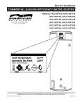
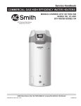
Service Handbook
COMMERCIAL GAS WATER HEATERS
PO Box 1597, 500 Princeton Road
Johnson City, TN 37605
FOR MODELS:
BCL3 95T199 6NOX, (A)BCL3 85T275 6NOX,
(A)BCL3 85T390 6NOX
ULTRA LOW NOx SERIES 100
INSTALLATION CONSIDERATIONS - PRE SERVICE CHECKS CONSTRUCTION - OPERATION & SERVICE - TROUBLESHOOTING
SERVICING SHOULD ONLY BE PERFORMED BY A QUALIFIED SERVICE TECHNICIAN
PRINTED IN THE U.S.A. 0413
324660-001
TABLE OF CONTENTS
INTRODUCTION . . . . . . . . . . . . . . . . . . . . . . . . . . . . . . . . . . . . . . . . . . . . . . . . . . . . . . . . . . . . . . . . . . . . . . 2
QUALIFICATIONS . . . . . . . . . . . . . . . . . . . . . . . . . . . . . . . . . . . . . . . . . . . . . . . . . . . . . . . . . . . . . . . . . . . . . 2
TOOLS REQUIRED . . . . . . . . . . . . . . . . . . . . . . . . . . . . . . . . . . . . . . . . . . . . . . . . . . . . . . . . . . . . . . . . . . . 3
INSTALLATION CONSIDERATIONS . . . . . . . . . . . . . . . . . . . . . . . . . . . . . . . . . . . . . . . . . . . . . . . . . . . . . . 4
GAS AND ELECTRICAL CHARACTERISTICS . . . . . . . . . . . . . . . . . . . . . . . . . . . . . . . . . . . . . . . . . . . . . . 4
GAS PRESSURE – REQUIREMENTS . . . . . . . . . . . . . . . . . . . . . . . . . . . . . . . . . . . . . . . . . . . . . . . . . . . . . 4
FEATURES AND COMPONENTS – ALL MODELS . . . . . . . . . . . . . . . . . . . . . . . . . . . . . . . . . . . . . . . . . . . 8
BLOWER AND BURNER ASSEMBLY . . . . . . . . . . . . . . . . . . . . . . . . . . . . . . . . . . . . . . . . . . . . . . . . . . . . . 9
SPARK IGNITER, FLAME SENSOR, SIGHT GLASS . . . . . . . . . . . . . . . . . . . . . . . . . . . . . . . . . . . . . . . . . . 11
VENTING . . . . . . . . . . . . . . . . . . . . . . . . . . . . . . . . . . . . . . . . . . . . . . . . . . . . . . . . . . . . . . . . . . . . . . . . . . . 12
VENTING TABLES – TECHNICAL VENTING DATA . . . . . . . . . . . . . . . . . . . . . . . . . . . . . . . . . . . . . . . . . . 14
OPERATION AND SERVICE . . . . . . . . . . . . . . . . . . . . . . . . . . . . . . . . . . . . . . . . . . . . . . . . . . . . . . . . . . . 16
DIAGNOSTIC SEQUENCE OF OPERATION – FLOW CHART . . . . . . . . . . . . . . . . . . . . . . . . . . . . . . . . . 17
SEQUENCE OF OPERATION – FLOW CHART . . . . . . . . . . . . . . . . . . . . . . . . . . . . . . . . . . . . . . . . . . . . . 18
LIGHTING AND OPERATING LABEL . . . . . . . . . . . . . . . . . . . . . . . . . . . . . . . . . . . . . . . . . . . . . . . . . . . . . 19
TROUBLESHOOTING . . . . . . . . . . . . . . . . . . . . . . . . . . . . . . . . . . . . . . . . . . . . . . . . . . . . . . . . . . . . . . . . 20
CONTROLS OVERVIEW - CONTROL BOX ASSEMBLY . . . . . . . . . . . . . . . . . . . . . . . . . . . . . . . . . . . . . . 21
PRESSURE SWITCHES – ALL MODELS . . . . . . . . . . . . . . . . . . . . . . . . . . . . . . . . . . . . . . . . . . . . . . . . . 22
HIGH LIMIT SWITCH/ DIGITAL THERMOSTAT . . . . . . . . . . . . . . . . . . . . . . . . . . . . . . . . . . . . . . . . . . . . . 23
CONTINUITY CHECK OF HIGH LIMIT (ECO) . . . . . . . . . . . . . . . . . . . . . . . . . . . . . . . . . . . . . . . . . . . . . . 25
UPPER TEMPERATURE PROBE CONTINUITY CHECK . . . . . . . . . . . . . . . . . . . . . . . . . . . . . . . . . . . . . 26
LOWER TEMPERATURE PROBE CONTINUITY CHECK . . . . . . . . . . . . . . . . . . . . . . . . . . . . . . . . . . . . . 27
IGNITION CONTROL . . . . . . . . . . . . . . . . . . . . . . . . . . . . . . . . . . . . . . . . . . . . . . . . . . . . . . . . . . . . . . . . . 28
START UP/ FLAME RECOVERY/ SAFETY LOCKOUT . . . . . . . . . . . . . . . . . . . . . . . . . . . . . . . . . . . . . . . 29
VARIABLE FREQUENCY DRIVE – ALL MODELS . . . . . . . . . . . . . . . . . . . . . . . . . . . . . . . . . . . . . . . . . . . 31
CHARACTERISTICS AND FUNCTIONS OF THE CONTROL TERMINALS . . . . . . . . . . . . . . . . . . . . . . . 32
VFD – BLOWER SPEED AND FREQUENCY READINGS . . . . . . . . . . . . . . . . . . . . . . . . . . . . . . . . . . . . . 32
WIRING DIAGRAM – ALL MODELS . . . . . . . . . . . . . . . . . . . . . . . . . . . . . . . . . . . . . . . . . . . . . . . . . . . . . . 33
Servicing should only be performed by a Qualified Service Technician
1
INTRODUCTION
The service handbook is designed to aid in servicing and troubleshooting American BCL3 Models commercial
water heaters in the field. No duplication or reproduction of this book may be made without the express
written authorization of the American Water Heaters.
The following text and illustrations will provide you with a step by step procedure to verify proper installation,
operation, and troubleshooting procedures. Additional quick reference data is included to assist you in
servicing these products.
The information contained in this handbook is designed to answer commonly faced situations encountered
in the operation of this product line and is not meant to be all inclusive. If you are experiencing a problem
not covered in this handbook, please contact American Water Heaters Technical Information at 1-800-4569805, by email at [email protected] or your local American Water Heaters representative for
further assistance. Our website at: www.americanwaterheater.com is also a resource for installation and
service information. This handbook is intended for use by licensed plumbing professionals and reference
should be made to the installation manual accompanying the product. This handbook contains supplemental
information to the product’s installation and operation manual.
QUALIFICATIONS
“Qualified Service Technician" or "Qualified Agency”
Installation and service of this water heater requires ability equivalent to that of a Qualified Agency (as defined
by ANSI below) in the field involved. Installation skills such as plumbing, air supply, venting, gas supply and
electrical supply are required in addition to electrical testing skills when performing service.
ANSI Z223.1 Sec. 3.3.85: “Qualified Agency” - “Any individual, firm, corporation or company that either
in person or through a representative is engaged in and is responsible for (1) the installation, testing or
replacement of gas piping or (2) the connection, installation, testing, repair or servicing of appliances and
equipment; that is experienced in such work; that is familiar with all precautions required; and that has
complied with all the requirements of the authority having jurisdiction.”
Service of this water heater requires ability equivalent to that of a Qualified Service Technician in the field
involved. Installation skills such as plumbing, air supply, venting, gas supply, electrical supply are required in
addition to electrical testing skills. Some products may require combustion testing equipment and certification.
If you do not possess these skills or do not have the proper tools you should not attempt to service this water
heater.
SERVICE WARNING
If you are not qualified (as defined by ANSI above) and licensed or certified as required by the authority
having jurisdiction to perform a given task do not attempt to perform any of the procedures described in
this manual. If you do not understand the instructions given in this manual do not attempt to perform any
procedures outlined in this manual.
SERVICE REMINDER
When performing any troubleshooting step outlined in this manual always consider the wiring and connectors
between components. Perform a close visual inspection of all wiring and connectors to and from a given
component before replacement. Ensure wires were stripped before being crimped in a wire connector, ensure
wires are crimped tightly in their connectors, ensure connection pins in sockets and plugs are not damaged
or worn, ensure plugs and sockets are mating properly and providing good contact.
Failure to perform this critical step or failing to perform this step thoroughly often results in needless down
time, unnecessary parts replacement, and customer dissatisfaction.
2
Servicing should only be performed by a Qualified Service Technician
TOOLS REQUIRED
•
Electrical multimeter capable of measuring continuity/ ohms, ac & dc volts, amperes, microamperes,
millivolts, and frequency (hz)
•
•
UEi Model DL289 or equivalent
Digital manometer + 60" w. c., resolution 0.01" increments
Note: A digital manometer is required for testing pressure switches and can replace a gas pressure
gauge, draft gauge or slack tube manometer for checking gas pressure.
•
UEi model EM200 or equivalent
•
Water pressure gauge w/lazy hand and hose bibb connection
•
Thermometer
•
1-1/16 Inch socket with extension for anode replacement
•
Phillips head screwdriver
•
Set of numbered drill bits
•
Standard screwdrivers
•
3/8, 7/16, 1/2 and 9/16 inch open end wrench
DIGITAL MANOMETER
DIGITAL MULTIMETER
WATER PRESSURE
TEST GAUGE W/LAZY
HAND AND HOSE BIBB
CONNECTION
Servicing should only be performed by a Qualified Service Technician
3
INSTALLATION CONSIDERATIONS
GAS AND ELECTRICAL CHARACTERISTICS
MODELS
All Models
GAS TYPE
Natural
GAS SUPPLY PRESSURE
MINIMUM
MAXIMUM
3.5" WC (0.87 kPa)
14.0" WC (3.45 kPa)
VOLTS/HZ
AMPERES
120/60
<5
All models require a minimum gas supply pressure of 3.5” W.C. The minimum supply pressure is measured
while gas is flowing (dynamic pressure). The supply pressure (dynamic) should never fall below 3.5” W.C.
The supply pressure should be measured with all gas fired appliances connected to the common main firing
at full capacity. If the supply pressure drops more than 1.5” W.C. as gas begins to flow to the water heater
then the supply gas system including the gas line and/or the gas regulator may be restricted or undersized.
The gas valve on all models has a maximum gas supply pressure limit of 14" W.C. The maximum supply
pressure is measured while gas is not flowing (static pressure).
GAS PRESSURE – REQUIREMENTS
Main line gas pressure to the water heater for natural gas should be between a maximum of 14" w.c. (3.45
kPa) static pressure and a minimum of 3.5" w.c. (0.87 kPa) dynamic pressure for Natural Gas.
A supply gas pressure regulator (service regulator) must be installed no closer than 3 feet (1 meter)
and no farther than 8 feet (2.4 meters) of equivalent length from the water heater's inlet gas connection.
1. Check gas line pressure with a manometer.
2. Cycle the burner on and off several times to check its operation.
3. Check the operation of the limit and operating controls.
4. Check the vent system seams and joints and ensure that there is no discharge of flue products into
the room.
5. Check the input rate.
Supply gas pressure shall be measured while the water heater is not firing (static pressure) and while the
water heater is firing at full capacity (dynamic pressure). If the supply gas pressure to the water heater is not
between the required minimum and maximum values given in table above, adjust the supply gas regulator
as necessary. Adjust the supply gas regulator(s) per the regulator manufacturer’s instructions to achieve the
required “static” and “dynamic” supply gas pressure.
MULTIPLE APPLIANCE INSTALLATIONS:
In multiple water heater installations or in installations where the installed water heater(s) share a common
gas supply main with other gas fired appliances; the supply gas pressures shall be measured at each water
heater with all gas fired appliances connected to a common main firing at full capacity.
In multiple water heater installations the supply gas line regulators shall be adjusted to provide gas pressure
to each water heater within the minimum and maximum supply pressure requirements listed in table above
with all gas fired appliances connected to a common gas main firing at full capacity.
Note: A pressure drop of more than 1.5” W. C. (0.37 kPa) when the main burner ignites is an indication of
an inadequate supply of gas and can lead to ignition failure, rough starts and/or rough operation. If a
drop of more than 1.5” W. C. (0.37 kPa) in supply gas pressure occurs when the main burner ignites,
ensure the supply gas lines and regulator(s) are properly sized and installed.
4
Servicing should only be performed by a Qualified Service Technician
AIR SUPPLY:
Stoichiometric or theoretical complete combustion requires 10 cubic feet of air per 1,000 BTU of gas supplied.
The National Fuel Gas Code also recommends an additional 2.5 cubic feet of “excess” air. For information
on minimum make-up air opening sizes for various building installations, refer to the National Fuel Gas Code
NFPA 54/ANSI Z223.1.
INSUFFICIENT MAKE-UP AIR, NEGATIVE AIR PRESSURE AND DOWNDRAFTS:
Downdraft Caused by Kitchen Vent Hood
A lack of combustion and ventilation air can create a negative ambient air pressure in the installed space. The
vent system on one or more gas fired appliances can experience down drafts due to the outdoor air pressure
being greater than the ambient air pressure in the installed space. Where multiple gas fired appliances are
installed, one or more gas fired appliances can “pull air” through the vent system(s) of other appliances
installed nearby.
One common example is in a restaurant installation where exhaust vent equipment was not considered in
sizing make-up requirements. This condition may result in air being back drafted by the restaurant exhaust
equipment through the heater causing the draft proving switch to open and/or erratic heater shutdown.
• Down drafts can cause flue gases to spill into the installed space.
Servicing should only be performed by a Qualified Service Technician
5
MAKE-UP AIR – DIRECT COMMUNICATION WITH OUTDOORS:
A fresh supply of make-up air for combustion can be supplied to the water heater through make-up air ducts,
which directly communicate with the outdoors. (Not Direct Vent.)
Two openings are required: one within 12 inches of the top of the enclosure and one within 12 inches
of the bottom of the enclosure. Each opening must have a free area of not less than 1 square inch per
4,000 BTU/Hr of the total input of all appliances within the enclosure. The lower opening primarily provides
combustion air. The upper opening provides vent dilution air and acts as a relief opening for flue gases
should the vent become obstructed or a downdraft condition occur.
Additionally, when the water heater is installed in a confined space and communicating with the outdoor air,
one permanent opening, beginning within 12 inches (30 cm) of the top of the enclosure, must be permitted
where the equipment has clearances of at least 1 inch (2.5 cm) from the sides and back, and 6 inches
(16 cm) from the front of the appliance. The opening must directly communicate with the outdoors and
must communicate through a vertical or horizontal duct to the outdoors or spaces (crawl or attic) that freely
communicate with the outdoors, and must have a minimum free area of a) 1 square inch per 3,000 BTU/Hr
(7cm2 per kW) of the total input of all equipment located in the enclosure and b) not less than the sum of the
areas of all vent connectors in the confined space.
CONTAMINATED AIR:
Corrosion of the flue ways and vent system may occur if air for combustion contains certain chemical vapors.
Such corrosion may result in failure and risk of asphyxiation.
Combustion air that is contaminated can greatly diminish the life span of the water heater and water heater
components such as hot surface igniters and burners. Propellants of aerosol sprays, beauty shop supplies,
water softener chemicals and chemicals used in dry cleaning processes that are present in the combustion,
ventilation or ambient air can cause such damage.
Do not store products of this sort near the water heater. Air which is brought in contact with the water
heater should not contain any of these chemicals. If necessary, uncontaminated air should be obtained from
remote or outdoor sources. The limited warranty is voided when failure of water heater is due to a corrosive
atmosphere. (See limited warranty for complete terms and conditions).
6
Servicing should only be performed by a Qualified Service Technician
AIR REQUIREMENTS:
For safe operation an adequate supply of fresh uncontaminated air for combustion and ventilation must be
provided. An insufficient supply of air can cause recirculation of combustion products resulting in contamination
that may be hazardous to life. Such a condition often will result in a yellow, luminous burner flame, causing
sooting of the combustion chamber, burners and flue tubes and creates a risk of asphyxiation.
Do not install the water heater in a confined space unless an adequate supply of air for combustion and
ventilation is brought in to that space using the methods described in the Confined Space section of the
Instruction Manual.
Never obstruct the flow of ventilation air. If you have any doubts or questions at all, call your gas supplier.
Failure to provide the proper amount of combustion air can result in a fire or explosion and cause property
damage, serious bodily injury or death.
CLOSED WATER SYSTEMS:
Water supply systems may, because of code requirements or such conditions as high line pressure, among
others, have installed devices such as pressure reducing valves, check valves, and back flow preventers.
Devices such as these cause the water system to be a closed system.
THERMAL EXPANSION:
As water is heated, it expands (thermal expansion). In a closed system the volume of water will grow when
it is heated. As the volume of water grows there will be a corresponding increase in water pressure due to
thermal expansion. Thermal expansion can cause premature tank failure (leakage). This type of failure is not
covered under the limited warranty. Thermal expansion can also cause intermittent Temperature-Pressure
Relief Valve operation: water discharged from the valve due to excessive pressure build up. This condition
is not covered under the limited warranty. The Temperature-Pressure Relief Valve is not intended for the
constant relief of thermal expansion.
CONTAMINATED AIR:
Corrosion of the flue ways and vent system may occur if air for combustion contains certain chemical vapors.
Such corrosion may result in failure and risk of asphyxiation.
Combustion air that is contaminated can greatly diminish the life span of the water heater and water heater
components such as hot surface igniters and burners. Propellants of aerosol sprays, beauty shop supplies,
water softener chemicals and chemicals used in dry cleaning processes that are present in the combustion,
ventilation or ambient air can cause such damage.
Do not store products of this sort near the water heater. Air which is brought in contact with the water
heater should not contain any of these chemicals. If necessary, uncontaminated air should be obtained from
remote or outdoor sources. The limited warranty is voided when failure of water heater is due to a corrosive
atmosphere. (See limited warranty for complete terms and conditions).
POWER SUPPLY:
The water heaters covered in this manual require a 120 VAC, 1Ø (single phase), 60Hz, 15 amp power
supply and must also be electrically grounded in accordance with local codes or, in the absence of local
codes, with the National Electrical Code, ANSI/ NFPA 70 or the Canadian Electrical Code, CSA C22.1.
Servicing should only be performed by a Qualified Service Technician
7
FEATURES AND COMPONENTS – ALL MODELS
Outlet Tube
Exhaust/Vent
Inlet Tube
T&P
Relief
Valve
Upper
Thermostat
Probe/ECO
Control Box
Assembly
Clean Out
Cover
Lower
Thermostat
Probe
Drain
Valve
The Eliminator
Combustion
Blower & Burner
Assembly
Gas Control
Valve
8
Combustion
Air Intake
Gas Supply Piping:
3/4" NPT Connection
Gas Supply Pressure:
Natural Gas - Min 3.5" WC,
Max 14.0" WC
Servicing should only be performed by a Qualified Service Technician
BLOWER AND BURNER ASSEMBLY
Fasteners (4)
Blower
Blower
Flange
Silicone
Gasket
Union
Adapter
Tube
Flange
Plate
Skirt Ring
Flange Gasket
Burner
Gas Control
Valve
Fasteners (4)
Brass Locknuts (3)
Brass Nuts/
Lock Washers (4)
Burner
Gasket
Flame
Sensor
Spark Igniter
BURNER REPLACEMENT:
1. Turn off the gas supply and electricity to the water heater.
2. Disconnect the spark ignition cable and ground wire plus the flame sensor wire at their connection points
on the flange plate.
3. Disconnect the hose tubes at the gas valve connection, blower outlet connection and fresh air intake
connection if necessary.
4. Disconnect the gas line at the union above the gas valve.
5. Remove the 4 fasteners joining the blower flange to the adapter tube. Save the silicone gasket between
the blower flange and the adapter tube.
6. Move the blower aside and support it so that it will not hang from the power connection wires.
Servicing should only be performed by a Qualified Service Technician
9
7. Remove the 4 brass nuts and 4 lock washers holding the flange plate to the skirt ring flange.
8. Pull the adapter tube/flange plate/burner assembly out of the combustion chamber. Take care not to
damage the spark igniter or flame sensor during the removal process.
9. Clean the flange plate and skirt ring flange surfaces to remove any portions of the old skirt ring flange
gasket.
10.Support the adapter tube/flange plate/burner assembly in a vertical position with the burner extending
downward.
11.Remove the 3 brass locknuts holding the adapter tube to the flange plate.
12.Separate the adapter tube from the flange plate.
13.Clean the adapter tube and flange plate surfaces removing any portions of the old burner gasket.
14.Remove the burner from the flange plate.
15.Insert the new burner into the flange plate and align the notch in the burner flange with the tab in the
flange plate.
16.Install the new burner gasket over the three studs extending from the flange plate.
17.Install the adapter tube on the flange plate with the 3 brass locknuts. Torque the nuts to 60 in.lb.
18.Install the new skirt ring flange gasket on the flange plate.
19.Insert the adapter tube/flange plate/burner assembly into the combustion chamber and engage the 4
studs through the mounting holes/slots in the flange plate. Install 4 lock washers and 4 brass nuts on
the studs and torque to 16 ft.lb.
20.Reinstall the blower and silicone gasket on the adapter tube flange using the 4 fasteners. Torque the
fasteners to 20 ft.lb.
21.Reconnect the gas line at the union above the gas valve.
22.Reconnect the spark ignition cable and ground wire plus the flame sensor wire at their connection
points on the flange plate.
23.Reconnect the hose tubes if removed in step 3.
24.Check that all gas connections and fasteners are tight.
25.Turn on the gas supply and electricity to water heater.
10
Servicing should only be performed by a Qualified Service Technician
SPARK IGNITER, FLAME SENSOR, SIGHT GLASS
The spark igniter and the flame sense rod are shown below. Also shown is the burner sight glass. These
features are typical for all models.
Burner
Flame Sensor
Spark Igniter
Sightglass
SPARK IGNITER / FLAME SENSOR / CONTROL TIMING
SPARK IGNITER
This water heater is equipped with a spark igniter. Do not damage the ceramic insulator. Inspect the igniter
ceramic insulator for any cracks. The spark gap between the spark rod and grounding rod is 1/8".
FLAME SENSOR
This water heater is equipped with a flame sensor. The flame sensor senses flame by passing a small
electric current through the flame. This type of flame sensing is also known as flame rectification. The
Ignition Control is looking for a minimum current of 0.7 micro amperes for the water heater to operate.
CONTROL TIMING
Pre-purge
Inter Purge
Trial for ignition
Tries
Flame Sensing
Loss of Flame
Reset
Note: 5 seconds delay between low and high fire rate.
30 seconds
30 seconds
4 seconds
3
Remote
Recycle
15 minutes auto reset
Servicing should only be performed by a Qualified Service Technician
11
VENTING
INSTALLATION – VENTING CATEGORY AND MATERIALS
BCL3 MODELS VENTING
Category I
• Non-condensing, negative pressure in vent, below atmospheric.
Type venting
• Must be installed Conventional Vent; uses room air for combustion and discharges flue
gases to the outdoor atmosphere through one pipe.
Vent materials
• B Vent.
MINIMUM CLEARANCES
This water heater is approved for installation on combustible flooring in an alcove with minimum clearance
from combustion construction as indicated in below Figure and Table.
In all installations the minimum combustible clearances from vent piping shall be 6” (15.2 cm). Vent piping
passing through a combustible wall or ceiling must be a continuous run (no joints) and retain 6” (15.2 cm)
clearance unless an approved reducing thimble is used.
A service clearance of 24” (61 cm) should be maintained from serviceable parts, such as Temperaturepressure relief valves, baffles, digital thermostats, cleanout openings or drain valves.
The units are approved for installation with side, rear and ceiling clearances as indicated below:
MINIMUM CLEARANCES TO COMBUSTIBLE OR NON-COMBUSTIBLE CONSTRUCTION:
MODELS
BCL3 95T199 6NOX
(A)BCL3 85T275 6NOX
(A)BCL3 85T390 6NOX
12
"A" RIGHT SIDE
0"
0 cm
0"
0 cm
0"
0 cm
"B" LEFT SIDE
0"
0 cm
0"
0 cm
0"
0 cm
"C" BACK
0"
0 cm
0"
0 cm
0"
0 cm
Servicing should only be performed by a Qualified Service Technician
"D" CEILING
12"
30.5 cm
12"
30.5 cm
12"
30.5 cm
EXTERIOR CLEARANCES
The illustration below shows the required clearances for venting units using natural draft venting.
The vent must extend at least 3 feet above the highest point where it passes through a roof of a building
and at least 2 feet higher than any portion of a building within a horizontal distance of 10 feet (for vents of 12
inches in diameter or less).
References: NFPA 54/ ANSI Z223.1 may allow reduction to 8 feet with a “listed vent cap.”
Servicing should only be performed by a Qualified Service Technician
13
VENTING TABLES – TECHNICAL VENTING DATA
TYPE B GAS VENT
Multiple Gas Fired Tank-Type Heaters
When venting multiple tank type heaters
using Type B vent pipe, follow the installation
diagram and tables below which give sizing
and data based upon NFPA 54 ANSI Z223.1.
MODEL BCL3 95T199 6NOX
Input: 199,000 Btu/hr
Total Vent Height (Feet)
Vent Connector Size: 6 inches
6
8
10
15
20
30
50
100
Input Btuh/hr
Rise
Vent Connector Diameter (Inches)
199,000
1 Ft.
7
7
7
6
6
6
6
6
199,000
2 Ft.
7
7
6
6
6
6
6
6
199,000
3 Ft.
6
6
6
6
6
6
6
6
Number of 199 Heaters
Combined Input (Btu/hr)
Manifold and Common Vent Diameters (Inches)
2
398,000
9
8
8
8
7
7
7
6
3
597,000
10
10
10
9
9
8
8
7
4
796,000
12
12
12
10
10
9
9
8
6
8
50
100
MODEL (A)BCL3 85T275 6NOX
Input: 275,000 Btu/hr
Total Vent Height (Feet)
Vent Connector Size: 6 inches
15
20
30
Input Btu/hr
Rise
Vent Connector Diameter (Inches)
275,000
1 Ft.
8
8
8
7
7
6
6
6
275,000
2 Ft.
8
8
7
7
7
6
6
6
275,000
3 Ft.
7
7
7
7
7
6
6
6
Number of 275 Heaters
Combined Input (Btu/hr)
2
550,000
10
10
9
9
8
8
7
7
825,000
1,100,000
14
14
12
14
12
14
10
12
10
12
9
12
9
10
8
9
6
8
10
50
100
3
4
MODEL (A)BCL3 85T390 6NOX
Manifold and Common Vent Diameters (Inches)
Input: 390,000 Btu/hr
Total Vent Height (Feet)
Vent Connector Size: 6 inches
Number of 400 Heaters
14
10
15
20
30
Input Btu/hr
Rise
Vent Connector Diameter (Inches)
390,000
1 Ft.
-
-
-
-
8
7
7
6
390,000
2 Ft.
-
-
-
8
8
7
7
6
390,000
3 Ft.
-
-
8
8
8
7
7
6
Combined Input (Btu/hr)
Manifold and Common Vent Diameters (Inches)
2
780,000
12
12
12
10
10
9
9
3
1,170,000
16
14
14
14
12
12
10
9
4
1,560,000
16
16
16
14
14
14
12
10
Servicing should only be performed by a Qualified Service Technician
8
TYPE B GAS VENT
Single Gas Fired Tank-Type Heater
When venting single tank type water heater using Type B vent pipe, follow the tables below which give sizing
and data based upon NFPA 54 ANSI Z223.1.
Total Vent Height (Feet)
6
8
Lateral (Feet)
MODEL BCL3 95T199 6NOX
Input: 199,000 Btu/hr
Vent Connector Diameter: 6 inches
Vent Type: Type B Double-Wall Gas Vent
Vent Connection: Connected directly to Vent
Number of Appliances: Single
Appliance Venting: Fan assist
Note: Refer to NFPA 54/ ANSI Z223.1 for
maximum vent diameter.
0
2
4
5
6
8
10
15
20
30
10
15
20
30
50
100
5
5
NA
5
NA
NA
5
5
5
6
5
5
NA
5
NA
NA
5
5
5
5
5
5
NA
5
NA
NA
5
5
5
5
30
50
100
5
6
NA
6
NA
NA
6
6
6
6
5
5
NA
5
NA
NA
6
6
6
6
5
5
NA
5
NA
NA
5
5
5
6
30
50
100
6
6
NA
6
NA
NA
6
6
6
6
6
6
NA
6
NA
NA
6
6
6
6
Minimum Vent Diameter (Inches)
6
6
6
NA
6
NA
NA
NA
NA
NA
6
6
NA
6
NA
6
NA
NA
NA
NA
6
8
5
6
NA
6
NA
NA
6
NA
NA
NA
5
5
NA
6
NA
NA
6
6
NA
NA
5
5
NA
5
NA
NA
5
6
6
NA
Total Vent Height (Feet)
Lateral (Feet)
MODEL (A)BCL3 85T275 6NOX
Input: 275,000 Btu/hr
Vent Connector Diameter: 6 inches
Vent Type: Type B Double-Wall Gas Vent
Vent Connection: Connected directly to Vent
Number of Appliances: Single
Appliance Venting: Fan assist
Note: Refer to NFPA 54/ ANSI Z223.1 for
maximum vent diameter.
0
2
4
5
6
8
10
15
20
30
10
15
20
Minimum Vent Diameter (Inches)
6
7
7
NA
7
NA
NA
NA
NA
NA
6
7
NA
7
NA
7
NA
NA
NA
NA
6
7
NA
7
NA
NA
7
NA
NA
NA
5
6
NA
6
NA
NA
6
6
NA
NA
5
6
NA
6
NA
NA
6
6
6
NA
Total Vent Height (Feet)
6
8
Lateral (Feet)
MODEL (A)BCL3 85T390 6NOX
Input: 390,000 Btu/hr
Vent Connector Diameter: 6 inches
Vent Type: Type B Double-Wall Gas Vent
Vent Connection: Connected directly to Vent
Number of Appliances: Single
Appliance Venting: Fan assist
Note: Refer to NFPA 54/ ANSI Z223.1 for
maximum vent diameter.
0
2
4
5
6
8
10
15
20
30
10
15
20
Minimum Vent Diameter (Inches)
7
8
8
NA
8
NA
NA
NA
NA
NA
6
8
NA
8
NA
8
NA
NA
NA
NA
6
7
NA
7
NA
NA
8
NA
NA
NA
6
7
NA
7
NA
NA
7
7
NA
NA
Servicing should only be performed by a Qualified Service Technician
6
7
NA
7
NA
NA
7
7
7
NA
6
6
NA
6
NA
NA
6
7
7
7
15
OPERATION AND SERVICE
SEQUENCE OF OPERATION:
1. Switch power on to unit.
2. Thermostat calls for heat.
3. VFD sends power to Blower.
4. Blower runs at low speed.
5. Combustion Blower initiates air flow through water heater closing the Prover Switch.
6. After 30 seconds, the Ignition Control provides power to the Spark Igniter and Gas Valve.
7. Ignition Control maintains spark for up to 4 seconds and monitors Flame Sensor to determine if
Burner is lit.
8. If the Flame Sensor does not detect proper flame, the Ignition Control shuts off the Gas Valve and
allows the Blower to purge the unit. At that time, the Ignition Control restarts with step 6. It will try and
ignite the main burners 2 more times. If the unit does not light, the Ignition Control will wait 15 minutes
and then restart at step 6. This cycle will continue until the unit lights or the power is shut off to the
unit.
9. If the Flame Sensor detects proper flame, the Ignition Control will allow the unit to operate until the
thermostat is satisfied.
10.Once the unit is satisfied, the Thermostat will shut off the Blower, Gas Valve and Ignition Control and
the unit will be in standby mode until another call for heat is initiated by the thermostat.
16
Servicing should only be performed by a Qualified Service Technician
DIAGNOSTIC SEQUENCE OF OPERATION – FLOW CHART
Servicing should only be performed by a Qualified Service Technician
17
SEQUENCE OF OPERATION – FLOW CHART
18
Servicing should only be performed by a Qualified Service Technician
LIGHTING AND OPERATING LABEL
FOR YOUR SAFETY READ BEFORE OPERATING
WARNING: If you do not follow these instructions exactly, a fire or
explosion may result causing property damage, personal injury
or loss of life.
FLAMMABLE
BEFORE OPERATING: ENTIRE SYSTEM MUST BE FILLED WITH WATER AND AIR PURGED FROM ALL LINES.
A. This appliance does not have a pilot. It is equipped with
an ignition device which automatically lights the burner.
Do not try to light the burner by hand.
B. BEFORE OPERATING smell all aroung the area for gas.
Be sure to smell next to the floor because some gas is
heavier than air and will settle on the floor.
WHAT TO DO IF YOU SMELL GAS
Do not try to light any appliance.
Do not touch any electric switch;
do not use any phone in your building.
Immediately call your gas supplier from a neighbor's
phone. Follow the gas suppliers instructions.
If you cannot reach your gas supplier, call the fire
department.
C. Use only your hand to push the control buttons. Never use
tools. If the control buttons will not push in, don’t try to
repair them, call a qualified service technician. Force or
attempted repair may result in a fire or explosion.
D. Do not use this appliance if any part has been under water.
Immediately contact a qualified installer or service agency
to replace a flooded water heater. Do not attempt to repair
the unit. It must be replaced!
OPERATING INSTRUCTIONS
1.
STOP! Read the safety information
above on this label.
2. Set the ON/OFF switch on the control box to
the “OFF” position.
3. Set the thermostat to the lowest setting.
4. This appliance is equipped with a device which
automatically lights the burner.
DO NOT TRY TO LIGHT THE BUNER BY HAND.
to clear out any gas.
5. Wait five (5) minutes
STOP! Follow “B”
If you then smell gas,
in the safety information above on this label. If
you don’t smell gas, go to the next step.
6. Turn on all electrical power to the appliance.
7. Set the ON/OFF switch on the control box to
the “ON” position.
8. Set the thermostat to the desired setting.
CAUTION: Hotter water increases the risk
of scald injury. Consult the instruction
manual before changing temperature.
9. If the appliance will not operate, follow the
instructions “TO TURN OFF GAS TO
APPLIANCE” and call your technician or gas
supplier.
WARNING: TURN OFF ALL ELECTRIC
POWER BEFORE SERVICING.
ON
OFF
TO TURN OFF GAS TO APPLIANCE
1. Set the thermostat to the lowest setting.
2. Set the ON/OFF switch on the control box to
the “OFF” position.
3. Turn off all electrical power to the appliance
if service is to be performed.
Servicing should only be performed by a Qualified Service Technician
19
TROUBLESHOOTING
COMPLAINT
*Water not hot enough.
*Insufficient hot water.
CAUSE
USER
Thermostat set too low.
Set thermostat dial to a
higher temperature
Upper and/or lower
temperature probe out of
calibration.
Call qualified agency.
Thermostat set too low.
Set thermostat dial to a
higher temperature
*See WATER TEMPERATURE
CONTROL WARNING on page Upper and/or lower
temperature probe out of
12 of Instruction Manual.
calibration.
Main manual gas shutoff
valve partially closed.
REMEDY
QUALIFIED AGENCY
Call qualified agency.
Check continuity and resistance
(Ohms) of upper and lower
temperature probes. Replace
probes if out of specification.
Check continuity and resistance
(Ohms) of upper and lower
temperature probes. Replace
probes if out of specification.
Open main manual gas
shutoff valve to fullest extent.
Heater too small for demand. Space usage to give heater
time to restore water
temperature.
Heater recovery is slower.
Call qualified agency.
Water temperature too hot.
Thermostat set too high.
Set thermostat to a lower
setting.
Rumbling.
Sediment accumulation on
bottom of tank.
Drain a quantity of water
through drain valve. If
rumbling persists, call
qualified agency.
Delime heater.
Ticking or metallic sounds.
Expansion and contraction normal.
Pounding or water hammer.
Air chambers in piping
have become waterlogged.
Thermal expansion tank
damaged, improperly
charged, or improperly sized.
Drain piping system and
refill. Heater must be off
while this is being done.
Check thermal expansion
tank charge pressure when
the water system pressure
is zero.
Follow the manufacturer's
instructions for proper charging of
the thermal expansion tank.
Water leaks.
Drain valve not closed tightly. If drain valve cannot be
closed tightly, replace.
Gas odors.
20
If leakage source cannot be
corrected or identified, call
qualified agency.
Shut off gas supply to heater
and close cold water inlet
valve to heater.
Possible gas leaks.
Shut off gas supply to heater
and call gas company at
once.
Check gas input. If incorrect, check
for inlet air blockage and/or flue
gas exhaust blockage.
Repair or in case of suspected
tank leakage, be certain to confirm
before replacing heater.
Servicing should only be performed by a Qualified Service Technician
CONTROLS OVERVIEW - CONTROL BOX ASSEMBLY
ON/OFF
Switch
Variable
Frequency
Drive
Digital
Thermostat
Blocked
Inlet Switch
Low Speed
I/O Module
Blocked
Outlet
Switch
High Speed
I/O Module
Ignition
Control
Blower
Prover
Switch
Servicing should only be performed by a Qualified Service Technician
21
PRESSURE SWITCHES – ALL MODELS
All models are provided with three pressure switches. These switches are essential to the safe and proper
operation of the unit. The switches are wired to the Ignition control in series. It is important to understand the
purpose of each switch.
Blocked Inlet Switch
Blocked Outlet Switch
Blower Prover Switch
BCL3 MODELS PRESSURE SWITCHES
PRESSURE SWITCHES
Blocked Inlet Switch
Blocked Outlet Switch
Blower Prover Switch
22
Model
BCL3 95T199 6NOX
(A)BCL3 85T275 6NOX
(A)BCL3 85T390 6NOX
BCL3 95T199 6NOX
(A)BCL3 85T275 6NOX
(A)BCL3 85T390 6NOX
BCL3 95T199 6NOX
(A)BCL3 85T275 6NOX/
(A)BCL3 85T390 6NOX
Setpoint (WC)
-0.67"
-0.59"
-1.00"
+4.80"
+2.65"
+5.35"
+0.38"
+0.46"
Servicing should only be performed by a Qualified Service Technician
Tolerance (WC)
+0.03"/-0.05"
+0.03"/-0.05"
+0.03"/-0.05"
+/-0.10"
+/-0.10"
+/-0.10"
+0.01"/-0.07"
+0.02"/-0.06"
BLOWER PROVER SWITCH
The blower prover switch is provided on the heater to verify that the fan is operating. It is a positive pressure
switch whose electrical contacts are normally open. The blower prover switch electrical contacts will close
on a rise in pressure as the blower increases the pressure in the burner. This switch is connected to the
blower outlet pressure tap by a piece of silicone tubing. This tubing must be connected in order for the switch
to close the electrical contacts.
BLOCKED OUTLET SWITCH
The blocked outlet switch electrical contacts are normally closed. The blocked outlet switch electrical
contacts will open on a rise in pressure.
BLOCKED INLET SWITCH
The blocked inlet switch electrical contacts are normally closed. The blocked inlet switch electrical contacts
will open when an increase in negative pressure (vacuum) occurs in the intake vent pipe. The switch
is connected to the pressure tap on the PVC pipe connected to the inlet of the blower. When this switch
prevents the unit from igniting, most likely the intake is blocked by some means. Verify that the air intake pipe
is free of obstructions that may prevent air from entering the unit.
HIGH LIMIT SWITCH/ DIGITAL THERMOSTAT
The digital thermostat contains the high limit (energy cut out) switch. The high limit switch interrupts burner
gas flow should the water temperature reach 203°F (95°C).
In the event of high limit switch operation, the water heater cannot be restarted unless the water temperature
is reduced to approximately 120°F (49°C). The manual reset button on the front of the control then needs to
be depressed.
Continued manual resetting of high limit control, preceded by higher than usual water temperature is evidence
of high limit switch operation.
Contact your dealer or qualified service technician if continued high limit switch operation occurs.
Manual
Reset
Temperature
Adjustment
Dial
To 120V
supply
(E2)
Display
LED Label
Fuse
To Lower (E4)
Temperature
Probe
Display LED's
To Pressure Switches, I/O Modules & Ignition Control (E1)
To Upper (E3)Temperature Probe
Servicing should only be performed by a Qualified Service Technician
23
DISPLAY LIGHTS – DIGITAL THERMOSTAT
LED
STATUS
INDICATION
Calling for heat
The ECO (Energy Cut-Out) has
opened.
Normal status. No action required.
•
Check for excessively hot water (203° F or
higher).
•
Check the resistance of the temperature
probes and continuity of the high limit (ECO).
No power
Check the breaker.
Tank is at a set temperature ± 2° F.
No action required.
Tank has cooled below 120° F.
Preceded by “ECO Open” indication.
24
ACTION
•
Push the manual reset button.
•
Check the resistance of the temperature
probes and continuity of the high limit (ECO).
Servicing should only be performed by a Qualified Service Technician
CONTINUITY CHECK OF HIGH LIMIT (ECO)
CONDITIONS:
•
Power On – No Hot Water.
•
Red, digital thermostat “Call for Heat” LED – On.
•
Turn Power OFF.
Continuity check of ECO (energy cut-out, high limit)
Black to Black wires of upper probe. Power is off.
IF.........
THEN............
Continuity is indicated
(ZERO “0.0” Resistance)
Continuity is not present
(meter reads “0.L”)
Water is less than 120° F
Opens at 203° F; closes at 193° F. If water is below 193° F,
continuity is correct.
Replace ECO sensor, if water temperature is below 193° F.
• Reset status LED should be on.
• Replace digital thermostat if control will not manually reset.
Servicing should only be performed by a Qualified Service Technician
25
UPPER TEMPERATURE PROBE CONTINUITY CHECK
CONDITIONS:
•
Power On – Water below temperature set point.
•
Red, digital thermostat “Reset Status” LED – OFF.
•
"Call for Heat" LED Off.
OHMS RESISTANCE TABLE
°F
OHMS
70°
120°
140°
180°
11,884
3,759
2,488
1,169
Upper Temperature Probe continuity check
Red wire to red wire – Turn supply power "Off" for this test.
IF.........
THEN............
Test indicates no continuity.
Continuity is indicated.
Replace probe.
Probe should be okay (also verify Ohms resistance for water
temperature). (Reading will be approximate.)
26
Servicing should only be performed by a Qualified Service Technician
LOWER TEMPERATURE PROBE CONTINUITY CHECK
CONDITIONS:
•
Main burner ignited.
•
Stored water is below temperature setting more than 5° F (Tank Average).
•
Power Off.
•
Plug disconnected from digital thermostat receptacle E4.
OHMS RESISTANCE TABLE
°F
OHMS
70°
120°
140°
180°
11,884
3,759
2, 488
1, 169
Lower Temperature Probe continuity check
Red wire to red wire – Turn supply power "Off" for this test.
IF.........
THEN............
Test indicates no continuity.
Continuity is indicated.
Replace probe.
Probe should be okay (also verify Ohms resistance for water
temperature). (Reading will be approximate.)
Servicing should only be performed by a Qualified Service Technician
27
IGNITION CONTROL
Each heater is equipped with an ignition control. The solid state ignition control, ignites the burner by utilizing a
spark igniter. The spark igniter shuts off during the heating cycle and the burner flame is sensed through a remote
flame sensor.
The ignition control will try to ignite the burner three times before lockout. The control waits 15 minutes before
trying again to ignite the burner. This is a continuous cycle.
This is a 24 VAC ignition control. The microprocessor circuit design provides precise, repeatable timing and
operating sequences. The on-board diagnostics with LED output make troubleshooting easy and ensures
safe and efficient operation.
WIRING TERMINALS
TERMINAL
TH/W
PV1
MV1
V2
GND
S1
HV
28
DESCRIPTION
Thermostat Input
Gas Valve Power
VFD High Speed Signal
Valve Ground
System Ground
Remote Flame Sensor
High Voltage Output
Servicing should only be performed by a Qualified Service Technician
START UP/ FLAME RECOVERY/ SAFETY LOCKOUT
START UP - HEAT MODE
When a call for heat is received from the thermostat supplying 24 volts to TH/W, the control will reset, perform
a self check routine, flash the diagnostic LED once in the first two seconds, and a pre-purge delay begins.
Following the pre-purge period, the gas valve is energized and sparks commence for the trial for ignition
period. The VFD high speed signal remains de-energized until flame is detected.
When flame is detected during the trial for ignition, the sparking process is terminated and the VFD high
speed signal is energized after a 5 second dwell period. The thermostat and burner flame are constantly
monitored to assure the system continues to operate properly. When the thermostat is satisfied and the
demand for heat ends, the gas valve and VFD speed signals are de-energized immediately.
FAILURE TO LIGHT - LOCKOUT
MULTI TRIAL CONTROL
Should the burner fail to light, or if flame is not detected during the first trial for ignition period, the gas valve is
de-energized. The control then goes through an interpurge delay before another ignition attempt. The control
will attempt two additional ignition trials before going into lockout and the valve relay will be de-energized
immediately. This ignition control has an automatic reset. If the thermostat is still calling for heat after 15
minutes the control will automatically reset and attempt to ignite the burner.
FLAME FAILURE- RECYCLE MODE
This control has the "recycle after loss of flame" function, upon loss of an established burner flame, the gas
valve is de-energized and the control proceeds to interpurge before attempting to relight the burner. The
ignition control will allow three tries for ignition including inter-purges. If the burner relights, normal operation
resumes. If the burner does not relight, the control will go into lockout as described in "failure to light".
Servicing should only be performed by a Qualified Service Technician
29
FAULT CONDITIONS
The water heater is equipped with an ignition control that incorporates a diagnostic system to assist in
troubleshooting the appliance. The indicator codes on the ignition module are as follows:
LED INDICATION
2 Flashes
3 Flashes
Steady On
FAULT MODE
Flame sensed without call for heat.
Ignition Lockout.
Internal Control Failure
The LED will flash on for 1/4 second, then off for 1/4 second during a fault condition. The pause between
fault codes is 3 seconds.
INTERNAL CONTROL FAILURE
If the ignition control detects an error in its software or hardware, all outputs are turned off and the LED
displays a steady ON condition. If an internal control failure is indicated, replace the ignition control.
TROUBLESHOOTING GUIDE FOR IGNITION CONTROL
SYMPTOMS
1. Control does not start
CAUSES
a. Miswired.
b. No 24V AC power supply at TH/W terminal.
c. Bad control, check LED for steady on or flashing
code (see above Table).
2. Thermostat on -no spark
a. Miswired.
b. No 24V AC power supply at TH/W terminal.
c. Bad control, check LED for steady on or flashing
codes.
3. Valve on - no spark during TFI
a. Shorted electrode -establish 1/8 inch gap.
b. Check high voltage cable.
c. Miswired.
4. Spark on - valve off
a. Valve coil open.
b. Valve wire disconnected.
c. Bad control, check voltage at gas valve terminals
PV1 and V2.
5. Flame okay during TFI - no flame sense after TFI a. Poor ground at burner.
b. Poor flame, check flame current.
c. Check flame rod position.
FLAME SENSOR CURRENT CHECK
Flame current is the current that passes through the flame from the sensor to ground. The minimum
flame current necessary to keep the system from lockout is 0.7 micro amps. To measure flame current,
connect analog DC microammeter to the FC-, FC+ terminals on the Ignition Control. Meter should read 0.7
microamps or higher. If the meter reads below "0" on scale, meter leads are reversed; disconnect power
and reconnect meter leads for proper polarity.
30
Servicing should only be performed by a Qualified Service Technician
VARIABLE FREQUENCY DRIVE – ALL MODELS
The BCL3 95T199 6NOX, (A)BCL3 85T275 6NOX and (A)BCL3 85T390 6NOX models have a variable
frequency drive (VFD) that controls the speed of the blower motor. The VFD receives a signal from the
thermostat and ignition control that instructs the VFD to transmit the proper frequency to the blower to
produce the proper blower speed and proper input rate.
Two conditions must be met for the variable frequency drive to start the blower at low speed:
1. 100 - 120VAC must be supplied to the VFD input.
2. The thermostat closes a contact through the low speed I/O module – VFD terminals LI1 and +24V.
Servicing should only be performed by a Qualified Service Technician
31
Two conditions must be met for the variable frequency drive to switch the blower from low speed to high
speed:
1. 100 - 120VAC must be supplied to the VFD input.
2. The ignition control closes a contact through the high speed I/O module – VFD terminals LI2 and
+24V.
CHARACTERISTICS AND FUNCTIONS OF THE CONTROL TERMINALS
Display:
•4 - digit display
•Display of numeric values and codes
TERMINALS
COM
LI1
LI2
+24V
FUNCTIONS
Common of analog and logic I/Os
Logic input for low speed
Logic input for high speed
+ 24 VDC supply provided by the drive
Line supply is at the top of the drive, the motor power supply is at the bottom of the drive.
VFD – BLOWER SPEED AND FREQUENCY READINGS
The logic inputs for the VFD are sent from the thermostat and ignition control through the low and high
speed I/O modules in the form of a contact closure. The chart below lists the nominal speed of the blower
and the frequency signal displayed by the VFD for low and high speed blower operation. If the water heater
exhibits poor run characteristics check the frequency display.
Nominal RPM – Frequency – VFD
Model
BCL3 95T199 6NOX
(A)BCL3 85T275 6NOX
(A)BCL3 85T390 6NOX
Nominal RPM
Frequency
Nominal RPM
Frequency
Nominal RPM
Frequency
Low Speed
1550
53 Hz
1475
50 Hz
1475
50 Hz
High speed
4050
138 Hz
2550
101 Hz
4250
144 Hz
32
Servicing should only be performed by a Qualified Service Technician
WIRING DIAGRAM – ALL MODELS
WIRING DIAGRAM FOR (A)BCL3 95T1996NOX, 85T2756NOX AND 85T3906NOX WHEN EQUIPPED WITH FENWAL
IGNITION CONTROL, WHITE-RODGERS THERMOSTAT, FASCO BLOWER AND ATV12 VARIABLE FREQUENCY DRIVE.
Servicing should only be performed by a Qualified Service Technician
33
NOTES
34
Servicing should only be performed by a Qualified Service Technician
NOTES
Servicing should only be performed by a Qualified Service Technician
35
COMMERCIAL GAS WATER HEATERS
Visit the "Information Central" link of
www.americanwaterheater.com for a listing of available Service Handbooks.
For additional information contact:
American Water Heaters
PO Box 1597, 500 Princeton Road
Johnson City, TN 37605
1-800-456-9805
www.americanwaterheater.com
©2013 American Water Heater Company
36
324660-001