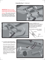
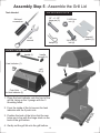
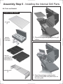
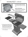
1
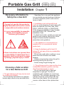
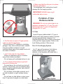
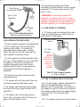
TM
Assembly and
Owner’s Manual
Portable
Gas Grill
VC0620P (
VC0680P (
VC0680N (
)
8000
Series)
8000
Series)
6000
Series
ASSEMBLER / INSTALLER:
Leave these instructions with the consumer.
CONSUMER / USER:
Read all of these instructions and keep them in a safe place for future reference.
FOR YOUR SAFETY
If you smell gas:
1 Shut off gas to the appliance.
2 Extinguish any open flame.
3 Open lid.
4 If odor continues, immediately call
your gas supplier or fire department.
FOR YOUR SAFETY
1 Do not store or use gasoline or other
flammable vapors and liquids in the
vicinity of this or any other appliance.
2 An unconnected liquid propane
cylinder should not be stored in the
vicinity of this or any other appliance.
FOR YOUR SAFETY: Never leave a grill unattended when in use.
Statement of Commitment
Congratulations and thank you for your purchase of your
new Vermont Castings grill. We are pleased that you have
recognized the value of the design, function, and quality
of components used in this product. We believe it is
among the finest on the market.
We are committed to producing quality products that your
family will enjoy for years to come. If for any reason we
have failed to meet or exceed your expectations, please
allow us the opportunity to make it right by calling us tollfree between the hours of 8:00 a.m. and 4:30 p.m.
United States: 1-800-944-8982
Canada: 1-800-668-5323
(It is recommended to avoid calling on Mondays,
when wait times may be prolonged.)
TM
410 Admiral Boulevard
Mississauga, Ontario Canada L5T 2N6
- A CFM Company -
For more information about our growing family
of barbecue grills, fireplaces, and outdoor
products, please visit our website at:
www.vermontcastings.com
Table of Contents
Page Number
Chapter 1 - INSTALLATION
4
Necessary Information . . . . . . . . . . . . . . . . . . . . . . . . . . .
Choosing a Safe Location . . . . . . . . . . . . . . . . . . . . . . . . .
Portable L.P. Gas Grills . . . . . . . . . . . . . . . . . . . . . . . . . . .
L.P. Gas Dealer Instructions . . . . . . . . . . . . . . . . . . . . . . .
Chapter 2 - ASSEMBLY INSTRUCTIONS
4
4
5-7
8
9
Step 1 ( Identifying Parts ) . . . . . . . . . . . . . . . . . . . . . . . . . 10
Step 2 ( Assemble Pillar to Base ) . . . . . . . . . . . . . . . . . . . 11
Step 3 ( Attach Grill Bottom ) . . . . . . . . . . . . . . . . . . . . . . . 12-13
Step 4 ( Side Tables ) . . . . . . . . . . . . . . . . . . . . . . . . . . . . 14
Step 5 ( Assemble Grill Lid ) . . . . . . . . . . . . . . . . . . . . . . . 15-16
Step 6 ( Internal Parts ) . . . . . . . . . . . . . . . . . . . . . . . . . . . 17-18
Installing an L.P. Gas Cylinder . . . . . . . . . . . . . . . . . . . . . 19
Connecting an L.P. Gas Cylinder . . . . . . . . . . . . . . . . . . . 20
Connecting to Natural Gas . . . . . . . . . . . . . . . . . . . . . . . . 21-22
23
Chapter 3 - USE and CARE
Leak Testing . . . . . . . . . . . . . . . . . . . . . . . . . . . . . . . . . . . 24
Lighting Instructions . . . . . . . . . . . . . . . . . . . . . . . . . . . . . 25-26
Using Your Grill . . . . . . . . . . . . . . . . . . . . . . . . . . . . . . . . . 27
Caring for Your Gas Grill . . . . . . . . . . . . . . . . . . . . . . . . . . 28
Cleaning and Maintenance . . . . . . . . . . . . . . . . . . . . . . . . 29
Replacement Parts . . . . . . . . . . . . . . . . . . . . . . . . . . . . . . 30-32
Troubleshooting Guide . . . . . . . . . . . . . . . . . . . . . . . . . . . 33-34
Chapter 4 - OUTDOOR COOKING / RECIPES
35
Recipes . . . . . . . . . . . . . . . . . . . . . . . . . . . . . . . . . . . . . . . 35-38
Warranty . . . . . . . . . . . . . . . . . . . . . . . . . . . . . . . . . . . . . . 39
3
Portable Gas Grill (
VC0620P
VC0680P
VC0680N
)( )
6000,
8000
Series
Installation Chapter 1
Necessary Information to
Safely Use a Gas Grill
· Operating this or any gas-fired appliance
in an enclosed area can produce a build-up
of carbon-monoxide, which could result in
injury or death.
2. Installation must conform with local
codes or, in the absence of local codes, with
either the National Fuel Gas Code, ANSI
Z223.1, NFPA 45 (USA), or CAN/CGA-B
149.2, Propane Installation Code (Canada)
and CAN/CGA-B 149.1 Natural Gas
Installation Code.
To check local codes, contact your local gas
dealer or gas company listed in the Yellow
Pages for recommended installation
procedures and regulations.
The gas fuel used by this product is
highly flammable and must be used in
a responsible and cautious manner.
It is your responsibility to assemble,
operate, and maintain your gas
barbecue grill properly.
3. This appliance is not intended to be
installed in or on a recreational vehicle
and/or boat.
4. Keep the barbecue grill at least 24
inches (61 cm) away from any combustible
construction.
· Do not use a grill under a ceiling or cover
where the heat or flame could cause
damage.
· Choose a level surface where the grill is
not facing directly into the wind.
· Avoid moving the grill during use.
If these instructions are ignored, there
is a possibility of a hazardous fire or
explosion which could result in property damage, physical injury or death.
5. The grill area must be clear and free from
combustible materials, gasoline, and any
other flammable liquids or vapors.
· Do not use lighter fluid or charcoal
briquettes in a gas grill. The flow of
combustion and ventilation air is not to be
obstructed. The ventilation openings of the
cylinder enclosure must be kept free and
clear from other debris. Do not store grill
covers or other items in the cylinder area.
Choosing a Safe Location
for a Gas Barbecue Grill
1. The gas barbecue grill may only be used
for cooking out-of-doors.
· Do not operate this barbecue in garages,
breeze ways, sheds or any enclosed area.
4
9. Make sure that the drip pan is in place
under the grill bottom.
· Hot drippings from cooking food could
damage the fuel supply system.
IMPORTANT: NEVER leave a grill
unattended when in use.
Portable L.P. Gas
Barbecue Grills
WARNING: Do not use natural gas in an
appliance designed for L.P. gas. Use only
liquid propane (L.P.) gas in an appliance
designed for L.P. gas.
L.P. Gas
Liquid Propane (abbreviated L.P.) gas is
stored under high pressure inside a cylinder
and will vaporize when released. It is
important that there are no leaky connections
on the grill fuel supply system. Refer to the
Leak Testing section of this manual.
6. Do Not store a spare L.P. gas cylinder
under or near this appliance.
Do not store an L.P. cylinder in a building,
garage or any other enclosed area. Instead,
store the cylinder outdoors in a well
ventilated area, away from people and out of
the reach of children.
The L.P. Fuel Supply System
An L.P. gas grill requires a fuel delivery
system made up of a L.P. gas supply
cylinder, a fuel regulator with hose and a
gas-control valve.
7. NOT FOR USE BY CHILDREN.
· Place your barbecue grill in a location
away from children and pets.
· Do not leave grill unattended when in use.
8. The outside of the barbecue grill will
become hot during use.
· To avoid burns, do not touch any hot grill
surface. If necessary, use a protective glove
when operating control knobs, tank shut-off
valve, or lid handle.
· Do not place combustible material, such
as cloth or plastic, on grill surface during
use.
· Do not lean on side tables or place more
than 15 pounds of weight on a side table.
The L.P. Fuel Supply System
5
4. The pressure regulator and hose
assembly provided is factory set at an outlet
pressure of 11 inches water column (.4 lb.
per sq. Inch).
Dual Burner
Fuel-Control Valve
Type 1 Fuel
Regulator
WARNING: Any attempt to adjust the
regulator is dangerous and could create a
situation causing personal injury or property
damage. Consult your L.P. gas dealer if you
think the regulator is not working properly.
Valve
Orifice
L.P. GAS SUPPLY CYLINDER
Fuel Supply
Hose
L.P. Cylinders can be obtained at the store
where you purchased your grill or from an
authorized L.P. gas dealer.
The L.P. Fuel Supply System
(the fuel regulator and hose)
Cylinder Control
Valve
FUEL REGULATOR AND HOSE
The fuel regulator supplied is equipped with
a Type 1 coupling nut. Do not attempt to
connect to any other L.P. cylinder not
equipped with a mating Type 1 cylinder
valve. This grill is not to be used with any
other cylinder connection device.
L.P. Gas
Cylinder
NOTE:
Some L.P.
grill models
DO NOT
include an
L.P. gas
cylinder
The fuel regulator and hose assembly with
the Type 1 fitting supplied must be used with
the appliance. Do not use a hose and
regulator assembly other than the one
supplied with the grill or a manufacturer’s
replacement fuel pressure regulator
assembly.
The L.P. Fuel Supply System
(L.P. gas cylinder)
The Type 1 connection system has the
following features:
L.P. GAS CYLINDER SPECIFICATIONS
1. The system will not allow gas to flow until
a positive connection has been made.
Any L.P. gas-supply cylinder used with this
grill must be approximately 12 inches
diameter and 18 inches high. The maximum
fuel capacity must be 20 pounds of propane.
Full-cylinder weight should be approximately
38 pounds (43.7 lbs. Nominal water
capacity).
2. The system has a thermal element that
will shut off the flow of gas between 240°F
and 300°F.
3. The system has a flow-limiting device
which, when activated, will limit the flow of
gas to 10 cubic feet per hour.
The L.P. cylinder must have a shut-off valve
6
percent full.
c.) If the information in (a.) and (b.) Is not
followed exactly, a fire causing serious injury
or death may occur.
terminating in a Type 1 L.P. gas-cylindervalve outlet. A Type 1 compatible cylinder
with a Type 1 cylinder valve has a positive
seating connection that does not permit gas
flow until a positive seal has been obtained.
The cylinder must be arranged for vapor
withdrawal. It must also include a collar to
protect the cylinder valve. A safety-relief
device having direct communication with the
vapor space of cylinder must be provided.
This will expel high-pressure gas if the
cylinder is overfilled or overheated.
All L.P. gas cylinders used with this
appliance shall be constructed and marked
in accordance with the specifications for L.P.
gas cylinders of the U.S. Department of
Transportation (DOT) or the National
Standard of Canada, CAN/CSA-B339,
Cylinders, Spheres and Tubes for
Transportation of Dangerous Goods and
Commission, as applicable; and shall be
provided with a listed overfilling-prevention
device. Read labels on the L.P. gas-supply
cylinder.
TRANSPORTING A FULL CYLINDER
WARNING: Handle a full cylinder with care.
Gas is under high pressure.
You should transport only one cylinder at a
time. Transport the cylinder in an upright and
secure manner with the control valve turned
off and the POL plug in place.
Do not transport a cylinder in the passenger
compartment of a vehicle.
Do not leave cylinder in direct sunlight or in
a high-heat area such as a closed car trunk.
High-heat areas could cause the relief valve
to vent gas.
Use a cylinder cap on the cylinder-valve
outlet during transport and when the cylinder
is not connected to the grill. Keep cylinder
valve closed when not in use.
DANGER: Do not insert any foreign objects
into the valve outlet. You may damage the
back check, A damaged back check can
cause a leak, which could result in explosion,
fire, severe personal injury or death.
HEAT SHIELD
WARNING: The heat shield must be
installed between the grill bottom and the
pillar.
Operating this grill without the heat shield
attached to the grill bottom would result in a
hazardous situation which could cause
serious property damage and possible
physical injury.
Allow only a qualified L.P. gas dealer to
fill or repair an L.P. gas-supply cylinder.
Inform the gas dealer if it is a new or used
cylinder to be filled. Caution the gas dealer
not to overfill the fuel cylinder.
After filling, have the gas dealer check for
leaks and that the relief valve remains free to
function.
Have the gas dealer weigh the cylinder
after filling to ensure that the cylinder is not
overfilled.
DANGER:
a.) Do not store a spare L.P. gas cylinder
under or near this appliance.
b.) Never fill the gas cylinder beyond 80
The heat shield in place
7
Take These Instructions to the L.P. Gas Dealer
The L.P. gas cylinder has a Type 1 cylinder
valve with a back-check module in its outlet
that will not permit gas to flow until an
evacuation device is installed. To purge the
L.P. gas cylinder, the back-check module must
be opened with an evacuation device.
When using a cylinder exchange, be sure the
exchanged cylinder is a Type 1 cylinder; a 510
POL cylinder will not fit a Type 1 regulator.
FILLING AND PURGING
TYPE 1 L.P. GAS CYLINDERS
PURGING AND EVACUATION DEVICES
FOR L.P. GAS CYLINDER WITH TYPE 1
CYLINDER VALVES
DANGER: Purging and filling of L.P. gas
cylinders must be performed by personnel who
have been thoroughly trained in accepted L.P.
gas industry procedures. Failure to follow this
instruction may result in explosion, fire, severe
personal injury or death.
A. Hose-end valve with a bleed port: Purging
can be accomplished using a hose-end valve
containing a bleed port, which also allows for
evacuation without the use of an adapter.
IMPORTANT: Purge new cylinders before
filling. This tank is easily filled with a standard
CGA 510 POL filling connection.
B. Hose-end valve without a bleed port:
When a hose-end valve does not have a bleed
port, a separate device must be used for
evacuation.
CGA-510 POL
C. Purging using a Type 1 connection: L.P.
gas cylinder evacuation can be accomplished
during each purging by using a Type 1
connection. The Type 1 valve outlet has 15/16” external ACME right-hand thread that will
accept this connection.
CAUTION: After purging or filling an L.P. gas
cylinder, do not insert a POL plug into the
valve outlet. Insertion of this plug will prevent
the back-check from closing. Use ONLY the
provided cap and strap attached to the outlet.
Close the cylinder valve knob before returning
the cylinder to the customer.
Example A
Filling a Type 1 Cylinder Valve
Example A: shows a CGA-510 POL fitting.
Example B: shows using a Type 1 POL fitting.
For proper purging procedures in the USA,
refer to: Safety Bulletin NPGA # 133, “Purging
L.P. Gas Cylinders,” and Safety Bulletin NPGA
#130, “Recommended Procedures for Filling
Cylinders.”
Type 1
(cut away to see fitting)
DANGER: Do not fill an L.P. gas cylinder
beyond 80% full. If this information is not
followed exactly, a fire causing serious injury
or death may occur.
Example B
8
Portable Gas Grill (
VC0620P
VC0680P
VC0680N
)( )
6000,
8000
Series
Assembly Instructions Chapter 2
Tools needed to assemble grill:
Getting Started
· flat-head screwdriver
· phillips-head screwdriver
1. Please follow the steps in the order that
they are presented.
2. Assemble the grill where you plan to use it.
3. You may want to place an old towel or
cloth at the assembly site to prevent nuts and
bolts from becoming lost.
4. Have a friend help. An assistant can make
the assembly easier by holding the parts in
place while you fasten the nuts and bolts.
5. To be ready to barbecue immediately, have
the L.P. gas cylinder filled by an authorized
L.P. dealer or cylinder exchange center.
(For side burner equipped grills)
· 3/8” open-end wrench*
· 7/16” open-end wrench*
* A socket set or an adjustable
3
/8
wrench may be used in place
of the open-end wrenches.
Unpacking the Grill Parts
1. Remove and set aside all inner boxes and
parts from the master carton.
2. Remove and set aside all wrapping paper
and additional packaging from the parts.
3. Do not destroy carton or packing until your
grill is completely assembled and operating to
your satisfaction.
Liquid Propane Models
7
/1
6
If a L.P. gas cylinder has been included with
your L.P. gas grill, it has been shipped empty
for safety reasons. To be ready to grill
immediately, please have the fuel cylinder
filled with L.P. gas by an authorized L.P. gas
dealer. Some L.P. gas grill models do not
include a L.P. gas cylinder.
Natural Gas Models
Natural gas grills require a connection to a
natural gas supply. The gas connection should
be made only by a qualified installer or a
licensed plumber. The gas supply line must
not be installed by the consumer.
Note: You may notice during assembly that hardware
bag “B” is used before hardware bag “A”. The
assembly procedure has been improved from the
original sequence to make assembly easier. However,
hardware packaging has not been changed.
9
Assembly Step 1 - Identifying the Grill Parts
Locate these parts:
handle
standoff (2)
Heat Indicator (1)
handle (1)
grill lid (1)
warming rack (1)
grill bottom
assembly (1)
cast iron
cooking grids
6100 series (1)
8100 series (2)
(burner
assembly
Installed)
grease pan (1)
rock grate (1)
heat shield (1)
side table (2)
pillar (1)
(knobs, ignitor,
valve, hose with
regulator installed)
base (1)
(2 locking casters and
2 non-locking casters
Installed)
cylinder retainer
wire (1)
Not Pictured:
ceramic briquettes (1 pkg)
master hardware bag (1)
(consisting of 1 each of A,B,C,D bags)
NOTE:
Not all models feature identical parts. Some components may differ,
but the functions and assembly are similar. Refer to the replacement
part listing in Chapter 3 for your model’s components.
10
Assembly Step 2 - Attach the Base to the Pillar
locking
caster
Tools Needed:
3/8”
wrench
7/16”
wrench
back side of base,
upside down
USE HARDWARE BAG A :
1/4-20 hex
nut (4)
1/4-20 x 3/4”
bolt (4)
LOCATE THESE PARTS:
back side of pillar,
upside down
pillar
assembly (1)
1. Lock the pre-assembled casters on base by
pushing down on the latch.
2. Set the pillar upside down.
3. Set the base upside down onto the pillar
bottom as shown, aligning the holes in the
base with holes in the pillar.
base assembly (1)
4. Insert the four bolts through the holes in the
pillar and base. Thread the locking hex nuts
onto bolts. Tighten the bolts and nuts with the
wrenches.
5. Carefully turn the assembly upright onto the
casters.
locking
casters
11
Assembly Step 3 - Attach Grill Bottom to Pillar
back side of grill
Tools Needed:
3/8”
wrench
7/16”
wrench
USE HARDWARE BAG B :
1/4-20
nut (4)
1/4-20 x 1”
bolt (4)
LOCATE THESE PARTS:
grill bottom
assembly (1)
1. Working from the back (open) side of the pillar,
set the heat shield on top of the pillar.
heat
shield (1)
2. Set the grill bottom on top of the heat shield. Line
up the burner tubes with the control valve orifices
inside the pillar. Adjust the grill bottom and heat
shield to line up the bolt holes.
3. Insert the bolts through the grill bottom and
tighten the nuts from inside the pillar.
12
Assembly Step 3 - Continued
IMPORTANT: Make sure the
control valve ends are properly
seated inside the burner tubes as
shown. (The control valve ends
are attached to the pillar; the
burner tubes are attached and
extend through the grill bottom.)
Improper installation and
connection of the burner tubes to
the control valves is dangerous
and may lead to damaging fire
and personal injury.
This illustration shows a proper
connection.
Venturi
Valve
4. Locate the two black igniter
wires beneath the grill bottom.
Press the metal contacts of
the loose ends of the wires
onto the metal pins of the
igniter unit. The position of the
wires is not relevant - either
wire may be connected to
either prong. It is important
that the wires are connected
securely.
13
Assembly Step 4 - Attach the Side Tables
USE HARDWARE BAG C :
Tools Needed:
3/8”
wrench
1/4-20 x 3/4”
bolt (8)
1/4-20 hex
nut (8)
LOCATE THESE PARTS:
7/16”
wrench
side table (2)
1. Insert the 3/4” bolts
through the holes in
the support brackets
of the side table.
2. Attach the side table
to the four holes
located in the side of
the grill bottom using
the locking hex nuts
provided.
3. Attach the opposite
side table the same
way.
14
Assembly Step 5 - Assemble the Grill Lid
USE HARDWARE BAG D :
Tools Needed:
1/4” x 1-1/8”
hinge pin (2)
flat-head
screwdriver
7/16”
wrench
hairpin (2)
LOCATE THESE PARTS:
handle (1)
handle
standoff (2)
Heat Indicator (1)
grill
lid (1)
Push Nuts
for Heat Indicator (2)
1. Place the heat indicator onto the front of the
grill lid, lining up the 3 prongs with the 3
mounting holes.
2. From the inside of the lid, secure the heat
indicator with the 2 push nuts.
3. Position the back of the lid so that the rear
holes are in line with the hinge struts on the
back of the grill bottom.
4. Gently set the grill lid onto the grill bottom.
15
1/4-20 hex
nut (4)
1/4-20 x 5/8”
bolt (4)
standoff
gasket (2)
Assembly Step 5 - continued
5. Hold the lid to align the hinge holes.
6. Insert a hinge pin through the hinge hole
in the lid and into the hole in the bottom
hinge strut.
4
7. After the hinge pin is in place, insert a
hair pin through the hole of the hinge pin
to secure it.
5
HINT: There is an air space between the
back of the lid and the grill bottom where
you can install the pins.
8. Repeat for the
opposite side.
standoff
standoff
gasket
grill lid
9. Raise the lid to attach
the front handle.
10. Attach one handle
standoff to the front
of the grill lid, as shown.
11. Insert one end of the handle into the
hole of the mounted standoff.
12. Place the other standoff onto the handle,
and while holding the handle in place,
assemble the opposite standoff to the lid
in the same manner.
16
3
Assembly Step 6 - Installing the Internal Grill Parts
No Tools are Needed.
LOCATE THESE PARTS:
rock grate
(1)
ceramic
briquettes
(1 package)
1. Place the single rock grate into the grill
bottom.
cast iron
cooking grids
6000 series (1)
8000 series (2)
warming rack
(1)
2. Open the package containing the
ceramic briquettes and place them on
the rock grate.
17
Assembly Step 6 - continued
3. It is important to properly arrange all
the ceramic briquettes onto the rock
grate to allow for good air flow during
use.
NOTICE THE SPACING:
The proper amount of briquettes are
supplied and there is no need to add
more. Some space between the
briquettes is necessary.
4. Set the porcelain coated cooking
grids, side by side, on the front and
back ledges formed inside the grill
bottom for a level cooking surface.
(6000 series grills are equipped with one large
single cooking grid in place of the 2 grids)
5. Set the warming rack onto the back
of the cooking grids.
18
Installing an L.P. Gas Cylinder
Obtain a filled L.P. gas cylinder. Read and
follow all directions on the cylinder and fuel
hose safety tags.
Items Needed:
L.P. Gas Cylinder
(1 FILLED)
WARNING: Connect the L.P. cylinder to the
grill outdoors only.
NOTE: Some
L.P. grill models
DO NOT include
an L.P. gas
cylinder
1. Working from behind the grill, set the
cylinder into the large round opening in
the grill base.
2. Position the cylinder-retainer wire around
the cylinder collar as shown.
LOCATE THESE PARTS:
3. Insert the right end of the wire into the
small opening in the base.
4. Flex the left side so that it fits into the
opposite opening on the left side of the
base.
cylinder retainer
wire (1)
grease drip
pan (1)
2
1
3
4
(Back side, under grill bottom)
19
Connecting the L.P. Gas Cylinder
7. Make sure the hose has no kinks or
sharp bends and clears any areas that will
become hot during use. Never put strain on
the hose where it joins a fitting. The rubber
fuel supply hose must not touch the bottom
grill casting during use.
8. Before lighting grill, check all connections
for leaks using a mild soapy-water solution.
Connecting the Regulator to Cylinder
9. Place an aluminum 3-1/2” x 6” loaf pan
into the opening in the heat shield located
beneath the grill bottom. During use the pan
will catch hot grease drippings that could
damage the fuel supply system.
1. The top knob on the supply cylinder must
be closed. See that the top cylinder knob is
turned clockwise to a full stop.
2. Check that all the grill burner knobs are
turned off.
(Back Side, Under the Grill Bottom)
3. Remove the protective caps from the
cylinder valve and coupling nut, if present.
4. Hold the regulator in one hand and insert
the nipple into the valve outlet. Be sure the
nipple is centered in the valve outlet. The
coupling nut connects to the large outside
threads on the valve outlet. Use care not to
cross thread the connection.
Grease
Drip Pan
5. Hand tighten the coupling nut clockwise
until it comes to a full stop. Tighten by hand
only. Do not use tools.
Heat
Shield
6. CAUTION: In the connection process,
the grill side of the connection will seal on
the back check in the valve, resulting in a
slight resistance. The connection requires
about one-half to three-quarters additional
turn to complete the connection.
NOTE: If you cannot complete the final
connection, disconnect the regulator and
repeat steps 4 through 6. If you are still
unable to complete the connection, do not
use this valve and regulator.
Install a Drip Pan in the Heat Shield
The grease pan is a 3-1/2”x6” aluminum loaf
pan available at most grocery stores.
20
Natural Gas Grills - Connecting to Natural Gas
(for specially equipped natural gas grills only)
DANGER: EXPLOSIVE AND FLAMMABLE!
If the appliance is for connection to natural
gas, the gas connections should be made by a
qualified installer or a licensed plumber. The
gas-supply line must not be installed by the
consumer.
A quick-connect coupling sleeve with 3/8”
female end is provided. Install the connector
socket at the pipe end, after the shut-off valve.
This must be installed where the grill will be in
use.
It is important to observe the safety
guidelines for choosing a safe location. The
gas supply must be shut off prior to installation
of the quick connector socket. Use only a
matching factory authorized quick-connect
plug with the quick-connect socket.
The valve-orifices and fuel supply hose
system necessary for use with natural gas is
different than the system required for L.P. gas.
Modification to the burner valve/orifices allow
the use of natural gas. An L.P. cylinder is not
needed.
Natural-gas units are equipped with a 12footlong quick-connect fuel hose in place of
the shorter hose/regulator attached to the
burner valve.
WARNING: Do not use liquid propane (L.P.)
gas in an appliance designed for natural gas.
Use only natural gas in an appliance designed
for natural gas.
Dust Cap
INSTALLATION FOR NATURAL GAS
The maximum inlet supply pressure is 11.0"
w.c. for propane gas and 7.0" w.c. for natural
gas.
The specified supply pressure is 11.0" w.c.
for propane gas and 7.0" wc. for natural gas.
Shut-off Valve
The piping system should be installed by a
qualified service technician in accordance with
the National Fuel Gas Code (NFPA 54/ANSI
Z223.1) in the U.S.A., including:
Connector Socket
1. The appliance and its individual shut-off
valve must be disconnected from the gassupply piping system during any pressure
testing of that system at test pressures in
excess of 1/2 psi (3.5 kPa).
Gas Flow
One example of an Individual Shut-Off
Valve with the Quick-Connect Socket.
Prior to inserting, turn on gas supply and test
all connections with an ammonia-free soap
and water solution. Apply this solution to the
stem of the shut-off valve and opening of the
socket to detect leaks. (See Leak Testing
Natural Gas Connections on the following
page).
2. The appliance must be isolated from the
gas-supply piping system by closing its
individual manual shut-off valve during any
pressure testing of the gas supply piping
system at test pressures equal to or less than
1/2 psi (3.5 kPa).
21
Natural Gas Grills - Connecting to Natural Gas
(for specially equipped natural gas grills only)
5. Push the plug into the connector until the
sleeve snaps forward to lock the fitting in
place. Turn on the shut-off valve. The flow of
gas to the appliance will be restricted if the
plug is not connected properly.
OPERATING THE QUICK-CONNECT
Follow all directions on tags attached to hose.
1. To connect the fuel-supply hose to the fuel
supply, the shut-off valve must be closed.
6. Test for gas leaks using an ammonia-free
soap and water solution.
2. Remove the dust cap from the connector
socket by sliding the connector sleeve back to
release the plug. Remove the dust cap from
the plug.
TO DISCONNECT THE FUEL SUPPLY
1. Pull connector sleeve back and pull plug
out of socket. This will automatically shut off
gas to the appliance.
Plug
2. Close the shut-off valve and install the dust
caps on the socket and plug. Always turn off
the fuel supply at the shut-off valve when the
grill is not in use.
LEAK TEST CONNECTIONS
3. Position the plug end of the fuel supply
hose into the sleeve opening.
Test all the fuel supply connections using an
ammonia-free soap and water solution equally
mixed. Never use fire to test for leaks.
1. Turn on the gas shut-off valve.
2. Coat all connections of the fuel supply
system, especially at the quick-connect.
Connector Sleeve
3. Watch for bubbles to indicate a leak.
4. If there is a leak, shut off the gas supply
and re-connect the hose to the socket. Re-test
for leaks.
4. Slide the connector sleeve back, firmly
push the fitting into the connector.
Do not use the grill if a leak is detected that
cannot be corrected in this manner or if the
hose and connections become damaged.
Replace damaged components with only
factory authorized parts.
Shut-off Valve
Do not strain or kink the fuel-supply hose.
See that the hose is kept clear of surfaces that
become hot during use.
Dust Cap
22
Portable Gas Grill (
VC0620P
VC0680P
VC0680N
)( )
6000,
8000
Series
Use and Care Directions Chapter 3
Leak Testing the
Fuel Supply System
Lighting Instructions
Replacement Parts
23
Leak Testing
DANGER
To prevent fire or explosion hazard:
· Do not smoke while performing a leak
test.
· Do not permit any sources of ignition
in the area when testing for leaks.
· Perform leak tests outdoors only.
· Never perform a leak test near a fire or
flame.
Perform a leak test each time the gas
supply cylinder is connected to the regulator.
Leak test any time a part of the gas system
is replaced. Perform a leak test at least once
each year whether the L.P. gas supply
cylinder has been disconnected or not.
Have a dealer check the cylinder for
deterioration after 10 years, according to
DOT regulations. Immediately replace
cylinder if any is found.
How to Check the Fuel Supply System for
Gas Leaks
IMPORTANT! Inspect the gas supply hose
regularly. If there are cuts, excessive
abrasion or wear, replace the hose prior to
operating the appliance.
1. Mix a solution of equal parts mild
detergent or liquid soap and water.
2. Turn off the burner control knobs.
3. Turn the top knob of the fuel-supply
cylinder counterclockwise one rotation to
open.
4. Apply the soap solution to all connections
of fuel-supply assembly.
Use only the hose replacement specified in
the parts list for your grill.
If no soap bubbles appear, the grill is fine
for use.
If bubbles form at the connections, there is
a leak. In case of a leak, try tightening the
joint. If necessary, replace the faulty part with
a replacement part recommended by the
manufacturer.
5. Turn off the knob on fuel-supply cylinder.
6. Turn on the burner control knobs for a
moment to release pressure in hose, then
turn the control knobs back off.
7. Wash off soapy solution with cold water
and towel dry.
Leak Testing the
Fuel Supply System
(arrows denote primary
areas to check)
WARNING: Do not attempt to repair the
cylinder valve. If it becomes damaged,
the cylinder must be replaced.
If you are unable to stop a leak, shut off the
gas supply at the cylinder valve. Remove the
cylinder from the grill. Call a gas appliance
serviceman or L.P. gas dealer. Do not use
appliance until the leak is fixed.
24
Lighting Instructions
IGNITER LIGHTING SYSTEM
CAUTION: Do not stand with head or arms
over the grill.
The Igniter System consists of an igniter unit,
a gas-collector box, one ceramic electrode,
and lead wires. Gas is collected in the metal
collector box located at the burner. When the
igniter knob is turned, an electric spark is
created at the ceramic electrode. The gas is
then ignited by the spark.
To test: Watch the electrode tip inside the gas
collector while activating the igniter. To avoid a
possible shock, do not touch the burner or
metal parts on igniter system while performing
igniter test. A visible spark should jump from
the electrode. The spark gap is set when the
electrode is installed.
If there isn't a spark, check the lead wires
and connections. The igniter wires should be
kept away from the grill bottom. Also check
that the ceramic electrode in the collector box
is not broken.
Sometimes dirt and rust at and around the
electrode can prevent an igniter spark. Clean
them with a degreaser or warm soapy water,
and dry. Remove rust from electrode tip and
metal surfaces by lightly sanding with an
emery cloth or fine-grain sandpaper.
STEP 5. To light using the igniter:
Push in and turn the right burner-control knob
counter-clockwise to the high setting.
STEP 6. Immediately turn the igniter knob
clockwise until you hear it click. Repeat 4 to 5
times if necessary.
The burner should light.
STEP 7. If the burner fails to light properly,
turn the burner control knob off. Also turn off
the L.P. cylinder knob. Wait five minutes before
attempting to light the burner again. This will
allow time for released gas to disperse.
HINT: If the burner does not light after trying
again, turn off burner-control knob, the L.P.
cylinder knob and try match lighting the grill
once the gas has cleared.
LIGHTING INSTRUCTIONS
(Read all the steps before beginning.)
STEP 1. Check the burner venturi tubes for
blockage from an insect nest (see,
“CLEANING THE BURNER VENTURI
TUBES”).
STEP 2. Ensure that both of the burnercontrol knobs are in the OFF position.
Operating the Control Knobs
Gas control knobs PRESS IN and rotate
counterclockwise.
TURN THE IGNITER KNOB CLOCKWISE
UNTIL IT CLICKS. Do NOT turn the igniter
knob counter-clockwise because it will strip the
knob and become unuseable.
STEP 3. OPEN GRILL LID
WARNING: Attempting to light the grill with
the lid down could cause an explosion.
STEP 4. Go behind the grill and turn on the
fuel supply valve. One counter-clockwise turn
is generally enough to open the valve.
25
Lighting Instructions
MATCH LIGHTING
CAUTION: Do not touch any hot grill parts.
The outside of the grill bottom becomes very
hot during use. It may be necessary to use
protective gloves.
IMPORTANT: The match lighting hole is
found under the front right corner of the grill
bottom. When match lighting the grill, use the
gas control knob on your RIGHT-HAND side
(closest to the match lighting hole).
HOW TO SHUT OFF THE GRILL
Repeat steps 1 to 4 of “Igniter Lighting
Instructions.”
STEP 1. Turn the burner-control knob(s) off.
The burner flame will go out.
STEP 5. To match light: push down and turn
the RIGHT burner control knob
counterclockwise to the high setting.
STEP 6.
IMMEDIATELY strike a long wooden match
and position the burning match through match
lighting hole in the grill bottom. Extend the
flame near a burner port in the bottom edge of
the burner. The burner should light.
STEP 2. Turn off the top L.P. cylinder valve
by turning the knob in a clockwise direction
until it stops.
IMPORTANT: Always have the gas shut off at
the L.P. cylinder valve when the grill is not in
use. The L.P. cylinder has a leak detection
feature which will restrict the amount of gas
flow to the burner if the tank shut-off valve has
not been turned off prior to the next use.
To light the other side of the burner, press in
and turn the opposite control knob. The flame
will track around the burner. Allow grill to
preheat with the grill lid closed for five to ten
minutes before cooking.
Locating the Match Lighting Hole
The match lighting hole is located beneath the
lower right corner of the grill bottom casting.
26
Using Your Gas Grill
TO BREAK IN A NEW GRILL
Before using it for the first time; operate the
grill with lid closed on a low setting for about
15 minutes. This will help burn away oil and
the smell of new paint. After the oil has burned
away, check the burner flame.
Regular use of your grill will actually help
keep it operating more smoothly. It is not
unusual for similar units to heat a little
differently.
BURNER'S FLAME
The high flame setting is for quick searing of
meat. Sear foods, then finish cooking on a
lower setting.
A medium setting works best for cooking
steaks, pork chops, and hamburgers.
The lowest setting works well for all roasts
and rotisserie foods. Even thick steaks, when
seared on a high setting first, will have a better
texture and be more juicy cooked on low.
CONTROL SETTINGS
Keep the grill lid closed and the grids in
place. Inspect the burner's flame by carefully
looking below and through the air-supply
openings in the grill bottom.
A good flame should be blue with some
yellow tip coming from the burner holes. Some
yellow tips on flames up to 1" in length are
acceptable as long as no carbon or soot
deposits appear.
If flames are excessively yellow and irregular,
the oil residue may not be completely burned
off, or the venturi may not be properly
positioned over the orifice(s). Allow grill to cool
before repositioning venturi over valve.
After a grill has been in use for a while it may
begin to have a more yellow flame. A build up
of food deposits, fats, or cooking seasonings
can cause yellowing of flames. Try cleaning
the burner to remove built-up residue. Check
for clogged burner holes or blocked venturi
tubes.
DUAL BURNER COOKING SYSTEM
The grill's burner may be operated to cook on
either side or both sides at once. This allows
for various styles of cooking.
1. Use a direct heat source when browning
meat or cooking hot dogs and hamburgers.
Check the food often.
2. Cook large-size foods (such as roasts,
turkey, or duck) on a low, direct heat. Place
food and water in foil pan with corrugated
bottom, adding water as needed.
3. If doing skillet or stir-fry cooking, limit the
amount of oil and direct heat used.
4. Cook foods that burn easily over an
indirect heat. Light one side of the burner and
place the food on the other side for cooking.
The food will cook slower but should be more
tender. This method of cooking also reduces
grease flare-up. Add a small pan of water to
help keep meat moist, replace the water as
needed.
5. Casseroles can be cooked in oven-proof or
foil pans using indirect heat.
6. Cook two foods at once using different
settings.
7. To add smoked flavor, try adding wood
chips in apple, mesquite, and hickory flavors.
BAD
FLAME
GOOD
FLAME
Yellow
Blue
Holes in Burner
FLAME CHECK
Checking the Burner Flame
27
Caring for Your Gas Grill
COOKING TIPS
CARING FOR YOUR GRILL
Prior to lighting the grill, coat the cooking grids
with cooking oil to prevent food from sticking.
Preheat the grill with the lid closed about five to
ten minutes before cooking. Cook with lid down
when possible. This will keep temperature even,
conserve fuel, improve food's flavor, and lessen
flare-ups.
Regular care of your grill will help keep it
operating properly. Cleaning or maintenance
may be done only when the grill is cool and with
the fuel supply turned off. Clean grill parts and
tighten loose hardware as needed.
Do not put grill parts in a self-cleaning oven as
the extreme heat could damage them. Do not
use a combustible or flammable cleanser on
grill. Do not use a commercial oven cleaner.
Never leave cooking food unattended. Frozen
meat and poultry should be thawed before
cooking. Trim the excess fat. Frozen fish and
vegetables will cook without thawing. However,
placing frozen food onto very hot porcelain grids
can crack the porcelain finish.
Always keep a small aluminum pan beneath
the grill bottom to catch grease drippings during
use. The grease pan is a 3-1/2”x 6” aluminum
loaf pan available at most grocery stores.
CAUTION: The grease pan and grill bottom
become extremely hot during use. To avoid
burns empty grease pan only when the grill is
cool.
Add salt to food after cooking to prevent it from
drying out. Brush naturally lean meat, poultry or
fish with cooking oil or margarine.
The small vent hole in the regulator must be
kept clean of dirt and debris. Keep the gassupply hose at least 3" away from any grill
surface that becomes hot during use.
Cook small pieces of tender foods in foil. Apply
barbecue, tomato, or sugar-based sauces no
sooner than the last ten minutes of cooking.
Turn food with a long-handled spatula or tongs.
REGULAR CLEANING AND UPKEEP
During operation, stand to side of grill when
opening the grill lid. Lift lid handle slowly in case
of a grease flare-up. Do not position any part of
your body directly above the cooking area.
Some flare-up is expected. It adds a smoky
flavor and sears food, but a major grease fire
can cause a potentially hazardous situation and
damage the grill.
After each cooking, shut the lid and turn control
knobs to highest setting for 5 minutes to burn off
grease drippings inside grill. Occasionally turn
the ceramic briquettes over before lighting to
burn off extra grease residue. Replace them with
fresh ones if they become too saturated with
grease.
Use a brass bristle brush on porcelain cooking
grids. Wash cooking grids with a mild soap, a
scrub brush and hot water. Use a mild soap and
hot water to wash all other grill parts.
IN CASE OF A MAJOR GREASE FIRE,
follow these steps:
1. Turn the burner-control knob(s) to off.
2. Stay away from grill.
3. Allow the fire to burn itself out.
4. After the fire is out and the grill is cool, shut
off the fuel supply valve at the fuel source.
5. Clean all parts.
6. Check for damage to the gas-supply hose,
burner valve, and burner. On L.P. appliances
also check the L.P. cylinder, L.P. cylinder valve,
regulator and hose. If any of these parts are
damaged, replace them with factory authorized
parts before operating the appliance again.
To refinish the outside of the aluminum grill
castings, clean and then lightly sand with a fine
sandpaper. Clean with a vinegar / water solution,
and rinse with water. When dry, paint with a high
temperature paint following directions on paint
can label.
IMPORTANT: NEVER leave a grill unattended
when in use.
28
Cleaning and Maintenance
Inspect and clean the burner regularly. Remove
grill components from the grill bottom necessary to
get to the burner inside. Use a wire bristle brush
to clean the burner surface. A straightened paper
clip is useful to remove debris from the small
burner ports.
If a blockage occurs inside the gas-control valve,
located behind the control panel, it may be
necessary to clear the valve orifices. Unscrew the
orifices from rear of the gas-control valve. Wash
the orifices and blow air through the small end
holes. Replace the orifices into the valve ends
when they are dry.
CLEARING THE BURNER VENTURI TUBES
WARNING: Never attempt to operate your grill
without orifices in the valve. A serious and
immediate fire hazard would result.
Spiders and other insects are known to
sometimes build homes inside a burner's venturi
tubes. This can become a serious problem. A
spider web or wasp nest inside the venturi tube
can block gas flow and can cause a fire at the gas
control valve. Such a fire can cause operator injury
and do serious damage to your grill. The venturi
tubes have fine screens to discourage spiders and
insects from building a nest inside. However, some
very small spiders may spin webs inside the
venturi tubes.
Replace the burner assembly into the grill bottom
after it is clean. IMPORTANT! Make sure the valve
orifices are inside venturi tubes. Secure burner to
the grill bottom, and reconnect the igniter wires.
Replace all other parts inside grill. Reconnect the
fuel cylinder to grill. Inspect the condition and
position of the gas-supply hose.
STORING AN L.P. GRILL
WARNING: Store an L.P. gas-supply cylinder
outdoors in a cool area, out of direct sunlight, and
away from people or pets.
Inspect the venturi tubes if a blockage is
suspected.
First, disconnect and remove the fuel source
from the grill.
Portable grills can be stored indoors without the
cylinder. If leaving it outdoors, cover the grill for
protection from weather.
Next detach and remove the burner from grill
bottom.
OPTIONAL ELECTRICAL ACCESSORIES
Insert a long pipe cleaner (about 20" long) inside
the venturi tubes to loosen and remove blockages.
Use care so as not to damage the screens inside
the tubes. A high pressured stream of water may
also be used.
If owner-supplied electrical accessories are used
with grill (such as an electric rotisserie), follow
specification statements included with the
accessory. Do not allow cord to touch any hot
surfaces that could melt the insulation.
IMPORTANT: If using an external electrical
source, the installed appliance must be electrically
grounded according to local codes or, in the
absence of local codes, with the National Electrical
Code, ANSI/NFPA 70 or the Canadian Electrical
Code CSA C22.1.
Venturi
Grounding Instructions: Use an appliance
equipped with a three-prong grounding plug for
your protection against shock hazard. It should be
plugged directly into a properly grounded threeprong receptacle. Do not remove the grounding
prong from a three-prong plug.
Pipe Cleaner
Burner
Cleaning the Venturi Tubes
29
Long detachable power-supply cords or
extension cords can also be used with care. The
marked electrical rating of the cord set or
extension cord should be at least as great as the
electrical rating of the appliance. If the appliance
is of the grounded type, the extension cord
should be a grounding-type 3 wire cord. Use
outdoor extension cords with a surface marked
with suffix letters “W-A” and with a tag stating
“Suitable for Use with Outdoor Appliances.”
Keep the connection to an extension cord away
from water and off the ground. Arrange the cord
so that it will not drape over the counter top or
tabletop where it can be pulled or tripped over.
Do not clean any electrical product with a water
spray or the like. Store electrical products
indoors out of reach of children when not in use.
6000, 8000 Series Replacement Parts
Replacement parts are available direct from our warehouse. Some components are not available
preassembled and may be ordered separately. For convenience, the following parts list is provided
along with a representation of the items listed. Charges for replacement parts and shipping may
apply.
For warranty replacements, proof of ownership and date of purchase is required.
Please call to receive a return authorization number before returning any grill components.
To order parts call toll free in the USA: 1-800-944-8982
in Canada: 1-800-668-5323
Model number cross reference: 6000 = VC0620P
8000 = VC0680P
8000N = VC0680N
Parts Enclosed
quantity
1
description
Parts Enclosed
part no.
Main Hardware Bag
AM000505
1
4
4
Hardware Bag “A”
1/4 x 20 x 3/4” Bolt
1/4 x 20 Hex Keps Nut
AM000105
AM000904
1
4
4
Hardware Bag “B”
1/4 x 20 x 1” Bolt
1/4 x 20 Hex Keps Nut
1
8
8
1
2
2
4
4
2
quantity
2
1
1
2
1
1
description
part no.
Aluminum Side Tables
Warming Rack
Lid Handle
Handle Standoff
Heat Shield
Aluminum Drip Pan
AX000505
AF000303
AP000102
AZ000802
AI000204
AI000302
AM000106
AM000904
L.P. Gas Models only
1
L.P. Gas Cylinder
1
Cylinder Retainer Wire
AW000202
AF000402
Hardware Bag “C”
1/4 x 20 x 3/4” Bolt
1/4 x 20 Hex Keps Nut
AM000105
AM000904
Hardware Bag “D”
1/4 x 1-1/8” Hinge Pin
Hairpin
1/4 x 20 x 5/8” Bolt
1/4 x 20 Hex Keps Nut
Handle Gasket
AM000908
AM000909
AM000207
AM000904
AM000704
Preassembled Components (see following pages)
1
Base Assembly
1
Pillar Assembly
1
Grill Bottom/Burner Assembly
1
Side Table Assemblies
30
Model 6000
Series Components
Model number reference: VC0620P
6000 Series Parts
quantity
1
1
1
1 pkg
description
Grill Lid
Rock Grate
Cast Iron Cooking Grid
Ceramic Briquettes
part no.
PX000105
AF000203
AZ000104
AQ000103
BOTTOM / BURNER ASSEMBLY
Bottom / Burner Assembly
1
consisting of:
Cast Brass Burner
1
Venturi Tube
1
Venturi Gasket
1
#8-32 x 1/2” Screw
8
Bottom Grill Casting
1
Collector Box
1
Collector Box Wire 8”
2
AZ001504
AZ000505
AM000503
AM000603
PX000205
AN000103
AN000203
PILLAR ASSEMBLY
Pillar Assembly
1
consisting of:
Aluminum Pillar (Green)
1
10-24 x 3/8” Screw
4
Printed Control Plate
1
10-24 x 1/2” Bolt
2
LP Valve / Regulator / Hose
1
Rotary Igniter Kit
1
Control Knob
2
Ignitor Knob
1
PXG00305
AM000203
AI000103
AM000103
AL000104
AN000303
AZ000703
AZ000603
Natural Gas Model only:
Natural Gas Valve / Hose
AL000204
1
(Replaces LP HVR AL000104)
BASE ASSEMBLY
Base Assembly
1
consisting of:
1
ROCTM Base
2
Locking Caster
2
Non-Locking Caster
AH000402
AH000104
AH000105
31
ModelModel
8000
Series Components
number reference: VC0680P and VC0680N
8000 Series Parts
quantity
1
1
2
1 pkg
description
Grill Lid
Rock Grate
Cast Iron Cooking Grids
Ceramic Briquettes
part no.
PX000104
AF000202
AZ001600
AQ000102
BOTTOM / BURNER ASSEMBLY
Bottom / Burner Assembly
1
consisting of:
Cast Brass Burner
1
Venturi Tube w/gasket
1
#8-32 x 1/2” Screw
8
Bottom Grill Casting
1
Collector Box
1
Collector Box Wire 8”
2
AZ001503
AZ000506
AM000603
PX000204
AN000103
AN000203
PILLAR ASSEMBLY
Pillar Assembly
1
consisting of:
Aluminum Pillar (Silver)
1
10-24 x 3/8” Screw
4
Printed Control Plate
1
10-24 x 1/2” Bolt
2
LP Valve / Regulator / Hose
1
Rotary Igniter Kit
1
Control Knob
2
Igniter Knob
1
PXS00305
AM000203
AI000103
AM000103
AL000104
AN000303
AZ000703
AZ000603
Natural Gas Model only:
AL000203
Natural Gas Valve / Hose
1
(Replaces LP HVR AL000103)
BASE ASSEMBLY
Base Assembly
1
consisting of:
1
ROCTM Base
2
Locking Caster
2
Non-Locking Caster
AH000402
AH000104
AH000105
32
Gas Grill Troubleshooting Guide
During the course of using your grill, you may occasionally encounter some cases where you have
questions as to how to keep your grill running properly. Following is a list of symptoms followed by the most
commonly used solutions.
Please, if you have a problem with your grill, and you are attempting to remedy it by yourself using the
following procedures, first read all warnings and safety precautions listed throughout the owner's manual.
For further assistance with operational and component issues, call our customer service center toll-free in
the USA: 1-800-944-8982; in Canada: 1-800-668-5323
_______________________________________________________________________________________
Burner Will Not Light
Corrective action:
Cause:
1) Lack of fuel
1) For LP, be sure that the tank valve is turned
on 1 to 1-1/2 turns. For natural gas, be sure
the gas valve is turned on all the way.
2) Burner venturi clogged with spider webs or insect 2) Clean inside venturi tubes with a small wire
nest
brush or pipe cleaner
3) Clean with a straight pin or paper clip and
3) Clogged or blocked orifices, burner ports, or
blow out
regulator hose-to-tank connection
4) a. Be sure igniter knob is fully seated (snapped
4) Igniter malfunctioninto place) on stem and if still no clicks replace
a. When rotating igniter knob no loud clicks are
both the igniter knob and igniter
heard
b. Igniter clicks but no spark in collector box
b. & c. Check wire connections and if still no
c. Collector box rusted out or damaged
spark replace collector box assembly
5) Burner venturi misaligned on orifices
5) Position venturi over orifices properly
6) Crimped fuel supply hose
6) Straighten hose
7) Bad regulator or damaged hose
7) Double check for proper and snug connections.
Replace if necessary
Comments: An unsuccessful ignition is often experienced when a gust of flames occurs due to the grill being
flooded with gas. This is a result of failure to follow the proper lighting instructions as explained in the owner's
manual. The gas is left on for over the allowed 3 to 5 seconds before ignition and finally it ignites. If the grill
fails to light with the igniter, use the match lighting instructions explained in the owner's manual.
_______________________________________________________________________________________
Burner Won't Stay Lit
Corrective action:
Cause:
1) Lack of fuel
2) Too cold or windy
1) Fill cylinder
2) Rotate grill to where the front faces the wind and
turn control knobs on high
3) Burner venturi misaligned on orifices
3) Position venturi over orifices properly
4) Burner venturi clogged with spider webs or insect 4) Clean inside venturi tubes with a small wire
nest
brush or pipe cleaner
_______________________________________________________________________________________
Yellow Burner Flame
Corrective action:
Cause:
1) Burner venturi clogged with spider webs or insect
nest
2) Food particles, grease or seasonings on burner
3) Air in tank (before filling tank was not purged)
4) Burner venturi misaligned
33
1) Clean inside venturi tubes with a small wire
brush or pipe cleaner
2) Clean burner with safe solutions (see Cleaning
section in owner's manual for details)
3) Use up LP tank (should improve with new tank)
4) Position venturi over orifices properly
Gas Grill Troubleshooting Guide - Continued
Grill Not Hot Enough or Uneven Heat
Corrective action:
Cause:
1) Shut everything off - both the tank and control
knobs. Then turn only the tank on 1 1/2 turns
followed by turning the control knobs on high
2) Clean inside venturi tubes with a small wire
brush or pipe cleaner
3) Clean with a straight pin or paper clip and
blow out
4) Rotate grill to where front is facing the wind
and turn control knobs to a higher setting
5) Position venturi over orifices properly
5) Burner venturi misaligned on orifices
_______________________________________________________________________________________
Grill Gets Too Hot
1) Improper lighting procedure (if you look closely
at the burner flames they'll be only 1/4" long on
the high setting when they should be at least 1")
2) Burner venturi clogged with spider webs or insect
nest
3) Clogged or blocked orifices, burner ports, or
regulator hose-to-tank connection
4) Extreme cold or windy conditions
Corrective action:
Cause:
1) Use leaner meat or add aluminum foil to the top
1) Grease flare up (caused by build up of grease
of the cooking grid before applying meat. Also
from extra fatty food or excessive amounts of
keep inside of grill and grease pan clean.
sauces or basting)
2) Turn control knobs to lower setting
2) Cooking temperature too high
3) Replace Hose Valve Regulator Assy. (HVR)
3) Malfunctioned regulator or damaged orifice
_______________________________________________________________________________________
Humming or Whistling Sound (comes from liquid propane passing through the regulator)
Corrective action:
Cause:
1) Tank overfilled or gas has expanded from getting
hot during the day
2) Tank has been turned on it’s side or upside down
1) Have LP dealer bleed tank and if humming
continues after use then replace HVR
2) Follow same steps as above
Note: The sound will usually cease during use and there is nothing to be concerned about. However, if it does
not cease, and you smell gas, shut the grill and L.P. tank off immediately and follow the above listed
corrective action.
_______________________________________________________________________________________
Popping Sound or Loud "Poofs" (comes from erratic burner flame)
Corrective action:
Cause:
1) Windy weather conditions
2) Improper lighting procedure (if you look closely
at the burner flames they'll be only 1/4" long on
the high setting when they should be at least 1")
1) Rotate grill to where the front is facing the wind
2) Shut everything off - both the tank and control
knobs. Then turn only the tank on 1 1/2 turns
followed by turning the control knobs on high
Note: Replace damaged components only with factory authorized parts.
34
Outdoor Cooking
Recipes Chapter 4
BEEF
FLAVORFUL FLANK STEAK
DISAPPEARING SHISH KEBOBS
1 beef flank steak (about 2 pounds)
3 tablespoons ketchup
1 tablespoon vegetable oil
1 tablespoon chopped onion
1 teaspoon brown sugar
1 teaspoon Worcestershire sauce
1 garlic clove, minced
1/8 teaspoon pepper
1/2 cup ketchup
1/2 cup sugar
1/2 cup soy sauce
1 teaspoon garlic powder
1 teaspoon ground ginger
2 pounds boneless beef sirloin steak
(1-1/2 inches thick),
cut into 1-1/2-inch cubes
1/2 fresh pineapple, trimmed and
cut into 1-inch chunks
2 to 3 small zucchini, cut into 1-inch chunks
1/2 pound whole fresh mushrooms
(medium size work best)
1/2 pound boiling onions, peeled
1 large green or sweet red pepper,
cut into 1-inch pieces
Place flank steak in an 11-in. x 7-in. x 2-in. glass
dish. Combine remaining ingredients; pour over
meat.
Cover and refrigerate for at least 4 hours. Remove
meat, discarding marinade.
Grill over hot grill until meat reaches desired
doneness, about 4 minutes per side for medium, 5
minutes per side for medium-well.
Combine first five ingredients; toss with beef.
Cover and refrigerate overnight.
Drain beef, reserving marinade.
Thread meat, pineapple and vegetables
alternately on long skewers.
Slice into thin strips across the grain to serve.
Yield: 8 servings.
Cook on a hot grill 15-20 minutes, turning often, or
until meat reaches desired doneness and
vegetables are tender.
BETTER BURGERS
1 pound ground beef or turkey
4 teaspoons prepared horseradish
2 teaspoons Dijon mustard
1 teaspoon paprika
1/4 teaspoon pepper
1/8 teaspoon salt, optional
4 hamburger buns, split
Simmer the marinade in a small saucepan over
low heat for 15 minutes. Remove meat and
vegetables from skewers; serve with marinade.
Yield: 6-8 servings.
HINT: Soak wooden or bamboo skewers in water
about a half hour prior to cooking.
In a bowl, combine the first six ingredients; mix
well. Shape into four patties. Grill until desired
doneness. Serve on buns.
Yield: 4 servings
35
POULTRY
PORK
GRILLED CHICKEN
BEST PORK RIBS
1 broiler/fryer chicken
(3-1/2 to 4 pounds), quartered
1/4 cup vinegar
1/4 cup butter or margarine
1/4 cup water
1/4 teaspoon dried thyme
1/4 teaspoon oregano
1/4 teaspoon rosemary
1/4 teaspoon garlic powder
1/8 teaspoon salt
1/8 teaspoon pepper
3 pounds country-style pork ribs
1/2 teaspoon garlic salt
1/2 teaspoon pepper
1 cup ketchup
1/2 cup packed brown sugar
1/2 cup honey
1/4 cup spicy brown mustard
2 tablespoons Worcestershire sauce
1-1/2 teaspoons liquid smoke, optional
Place ribs in a large kettle or Dutch oven; sprinkle
with garlic salt and pepper. Add enough water to
cover. Cook on your kitchen stove and bring to a
boil. Reduce heat; cover and simmer for 1 hour or
until juices run clear and ribs are tender; drain.
Meanwhile, combine the remaining ingredients.
Remove ribs from kettle to barbecue the ribs. Grill
ribs, uncovered, over medium heat for 10-12
minutes, basting with sauce and turning
occasionally. Yield: 4 servings.
Place chicken in a shallow glass dish. In a small
saucepan, combine all remaining ingredients; bring
to a gentle boil. Remove from the heat. Pour over
chicken. Cover and refrigerate for 4 hours, turning
once. Drain and discard marinade. Grill chicken,
covered, over medium heat for 30-40 minutes or
until juices run clear. Yield: 4 servings.
TASTY TURKEY
HMM - HMM HAM STEAK
1/4 cup soy sauce
1/4 cup vegetable oil
1/4 cup apple juice
2 tablespoons lemon juice
2 tablespoons dried minced onion
1 teaspoon vanilla extract
1/4 teaspoon ground ginger
Dash of garlic powder
Dash of pepper
2 turkey breast tenderloins
(about 1/2 pound each)
1-pound ham steak, 1/2 inch thick
1 tablespoon Dijon mustard
1 tablespoon honey
1 tablespoon apricot preserves
Cut outer edge of fat on ham diagonally at 1-inch
intervals to prevent curling (do not cut into ham). Mix
mustard, honey and preserves.
Grill ham uncovered 4 to 6 inches from medium-high
heat 4 minutes. Turn ham; brush with mustard
mixture. Grill 4 minutes longer. Turn ham; brush with
remaining mustard mixture. Grill about 2 minutes
longer or until heated through. Yield: 4 servings.
In a large resealable plastic bag or shallow glass
dish, combine the soy sauce, oil, apple juice, lemon
juice, onion, vanilla, garlic powder and pepper. Add
turkey; seal or cover and refrigerate for at least 2
hours. Discard marinade. Grill turkey, covered, over
medium heat for 8-10 minutes per side or until
juices run clear. Yield: 4 servings.
GRILLED HAM & SWISS SANDWICHES
1/4 cup butter, softened
2 tablespoons horseradish mustard
2 tablespoons chopped onion
2 tablespoons poppy seed
6 ounces thinly sliced ham
6 ounces sliced Swiss cheese
6 sandwich buns
Mix butter, mustard, onion and poppy seed. Spread
mixture on both halves of each bun; layer a slice of
Swiss cheese and several ham slices between
halves. Wrap each sandwich in foil and grill for 20
minutes. Serve warm. Yield: 6 servings.
36
FISH / SEAFOOD
SIDE DISHES
SHRIMP COMBO PACKETS
RICE ON THE SIDE
4 cups peeled potatoes (about 1-1/4 lbs.),
sliced 1/8-inch thick
1 cup sliced leeks or mild onions
1 cup chopped plum tomatoes
20 jumbo shrimp (about 1 lb.)
peeled and deveined
4 Tablespoon butter
2 teaspoon dill weed, crushed
1 teaspoon garlic powder
1 teaspoon salt
1/2 teaspoon ground black pepper
1-1/3 cups uncooked instant rice
1/3 cup sliced fresh mushrooms
1/4 cup chopped green pepper
1/4 cup chopped onion
1/2 cup chicken broth
1/2 cup water
1/3 cup ketchup
1 tablespoon butter or margarine
In a 9-in. round aluminum foil pie pan, combine the
first seven ingredients. Dot with butter. Cover with
heavy-duty foil; seal edges tightly. Grill, covered, for
14 to 15 minutes or until liquid is absorbed. Fluff with
a fork and serve immediately. Yield: 6 servings
On work surface, place 4 sheets of heavy-duty or
doubled aluminum foil each about 20 inches long. In
the center of each, arrange 1/2 cup potatoes,
overlapping slightly; top with 1/4 cup each leeks and
tomatoes and 5 shrimp.
AU GRATIN POTATO POUCHES
4 cups frozen O'Brien potatoes (16 ounces)
1 tablespoon vegetable oil
1/2 teaspoon seasoned salt
3/4 cup shredded Cheddar cheese ( 3 ounces)
Dot with 1 tablespoon butter; sprinkle with 1/2
teaspoon dill weed, 1/4 teaspoon garlic powder, 1/4
teaspoon salt and 1/8 teaspoon black pepper.
Arrange remaining potatoes over shrimp,
overlapping slightly.
Spray 18x13-inch foil with piece of heavy-duty
aluminum foil with cooking spray. Place potatoes on
foil. Drizzle with oil; sprinkle with seasoned salt.
Wrap foil securely around potatoes. Grill on medium
heat 30 minutes, turning once. Carefully open
packet; sprinkle cheese over potatoes. Cover loosely
and let stand for 4 to 5 minutes or until cheese is
melted. Yield: 6 servings.
Bring long sides of foil together over mixture,
allowing space for heat circulation and expansion;
fold down to seal. Fold up short ends; crimp to seal.
Place on grill. Cook until potatoes are tender and
shrimp are cooked, approximately 20 minutes on the
grill. Carefully lift pouch from grill and place in
serving dish. Open carefully, allowing steam to
escape. Yield: 4 servings.
GRILLED BREADS
SUPER SALMON
1 One pound loaf frozen bread dough,
white or honey wheat, thawed
2 tablespoons olive oil
Suggested Toppings for bread:
Sliced fresh tomatoes with basil and grated
Fontina cheese, OR Grilled onions, OR Fresh
herbs and garlic, OR Grated Parmesan cheese
and garlic, OR pizza sauce with grated
mozzarella cheese and sliced olives, OR feta
cheese and black olives
1-1/2 cups packed brown sugar
6 tablespoons butter or margarine, melted
3 to 6 tablespoons lemon juice
2-1/4 teaspoons dill weed
3/4 teaspoon cayenne pepper
1 salmon fillet (about 2 pounds)
Lemon-pepper seasoning
In a small bowl, combine the first five ingredients;
mix well. Remove 1/2 cup to a saucepan; simmer
until heated through. Set aside remaining mixture for
basting. Sprinkle salmon with lemon-pepper. Place
on grill with skin side down. Grill, covered, over
medium heat for 5 minutes. Brush with the reserved
brown sugar mixture. Grill 10-15 minutes longer,
basting occasionally. Serve with the warmed sauce.
Yield: 6-8 servings.
Divide dough into 4 equal pieces. Flatten each into a
6-inch round. Brush one side of each round with oil.
Place oiled-side down on an oiled grid at medium
heat. Cover and cook until browned and firm, about
5 minutes. Brush tops with oil; turn breads over. Top
cooked side of bread with a suggested topping.
Yield: 4 servings.
37
VEGETABLES
DESSERTS
ONION BLOOM
CINNAMON APPLES
1 Bermuda onion
1 tablespoon butter
2 teaspoons honey
1/2 teaspoon Worcestershire sauce
4 medium tart apples, cored
4 teaspoons brown sugar
1/4 cup red-hot candies
Vanilla ice cream, optional
Peel onion; cut 1/2 -inch slice from top of onion and
leave root end. Cut onion from top into 8 wedges to
within 1/2-inch of root end. Gently pull wedges apart.
Brush 12-inch square of heavy-duty aluminum foil
with vegetable oil. Place onion on square; loosely
shape foil around onion. Sprinkle onion with butter,
honey and Worcestershire sauce. Wrap foil securely
around onion. Cover and grill onion at medium heat
50 - 60 minutes or until very tender.
Yield: 1 serving.
Place each apple in the center of a piece of heavy
duty foil (12 in. square). Spoon I teaspoon sugar and
I tablespoon red-hots into the center of each apple.
Fold foil around apple and seal tightly. Grill, covered,
over medium-hot heat for 30 minutes or until apples
are tender. Carefully transfer apples and syrup to
bowls. Serve warm with ice cream it desired.
Yield: 4 servings.
VEGETABLES ON A STICK
3 medium ripe peaches, halved and pitted
1 cup fresh blueberries
2 tablespoons brown sugar
2 tablespoons butter or margarine
1 tablespoon lemon juice
SUMMER MEDLEY
2 medium zucchini, cut into 1-inch slices
2 medium yellow summer squash,
cut into 1-inch slices
1/2 pound whole fresh mushrooms
1/3 cup olive or vegetable oil
2 tablespoons lemon juice
1-1/2 teaspoons dried basil
1-1/2 teaspoons dried parsley flakes
3/4 teaspoon garlic powder
3/4 teaspoon dried oregano
1/2 teaspoon salt
1/8 teaspoon pepper
Place each peach half, cut side up, on a double
thickness of heavy duty foil (12 in. square).
Sprinkle each with about 2 tablespoons blueberries,
1 teaspoon of brown sugar, 1 teaspoon butter and
1/2 teaspoon lemon juice. Fold foil around the
peaches and seal tightly. Grill, covered, over
medium-low heat for 18-20 minutes or until the
peaches are tender.
Yield: 3 servings.
On skewers, alternately thread zucchini, yellow
squash and mushrooms. In a bowl, combine the
remaining ingredients. Brush some of the mixture
over vegetables. Grill, uncovered, over medium heat
for 10-15 minutes or until vegetables are tender,
turning and basting occasionally with herb mixture.
Yield: 4 servings.
MEXICAN SMORES
1/2 cup creamy peanut butter
4 flour tortillas (8 inches)
1 cup miniature marshmallows
1/2 cup miniature semisweet chocolate chips
Vanilla ice cream
HOW TO GRILL FROZEN VEGETABLES
Spread 2 tablespoons of peanut butter on each
tortilla. Sprinkle 1/4 cup marshmallows and 2
tablespoons chocolate chips on half of each tortilla.
Roll up, beginning with the topping side. Wrap each
tortilla in heavy-duty foil; seal tightly. Grill, covered,
over low heat for 5-10 minutes or until heated
through. Unwrap tortillas and place on dessert
plates. Serve with ice cream.
Yield: 4 servings.
Tear off a 36x18-inch piece of heavy duty foil. Fold in
half to make an 18-inch square. Fold up sides, using
your fist to form a pouch. Place one 10-ounce
package frozen vegetables in center of pouch.
Season with salt and pepper; top with a pat of butter
or margarine. Fold edges of foil to sea] pouch
securely, leaving space for expansion of steam. Grill
over medium-hot until vegetables are cooked. Allow
about 20 minutes for peas and other small
vegetables; allow more time for larger vegetables.
Turn the package of vegetables frequently.
38
Manufacturer’s Limited Warranty
The Vermont Castings grill is guaranteed against broken or damaged parts at the time
of purchase. Components are guaranteed against defect as follows: All cast-aluminum
parts are warranted against burn through, rust, and structural failure excluding paint,
neglect, or abuse, for 75 years from the date of purchase. The cast-brass burner (only)
has a limited warranty of 25 years from date of purchase. If the burner should fail to
operate during the warranty period, Vermont Castings will prorate the cost of a
replacement burner. (Pro-rated consumer cost for burner replacement: up to 5 years free replacement; 6 to 10 years - 20% of replacement cost; 11 to 15 years - 40% of
replacement cost; 16 to 20 years - 60% of replacement cost; 21 to 25 years - 80% of
replacement cost) All other parts carry a 5-year limited warranty, except paint, which is
guaranteed to be free of defects for 90 days. L.P. cylinders (on propane models only)
are warranted by the cylinder manufacturer.
This warranty is void if the grill collar, heat shield and heat gaskets are removed from
the grill. This warranty does not cover damage or issues related to neglect, abuse, or
modifications to the product. Repair labor costs are the responsibility of the consumer.
All parts that meet the warranty requirement will be shipped at no-charge via the
discretion of the Customer Service Department (ground shipments, US Mail, or Parcel
Post ONLY). Any Special handling charges (i.e. Second Day, Overnight, etc.) will be the
responsibility of the consumer.
All warranty claims apply only to the original purchaser and require a proof of purchase
verifying purchase date. Do not return parts to our address without first obtaining a
return authorization number from our customer service. This service is available by
calling toll free in the USA: 1-800-944-8982; in Canada: 1-800-668-5323
This warranty may give you specific legal rights that vary by state.
TM
410 Admiral Boulevard
Mississauga, Ontario Canada L5T 2N6
- A CFM Company -
www.vermontcastings.com
©2004 Vermont Castings - a CFM company
The Vermont Castings logo, R.O.C.TM (Rugged Outdoor CompositeTM)
are trademarks of Vermont Castings and not to be used without express
permission by the owners and managers of Vermont Castings.
Patents Pending
USA 1998-2004
Revision A: February, 2004
Part No. AO000118