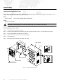
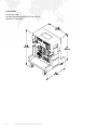
1
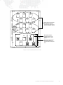
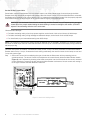
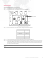
WWW.PRG.COM
PRG SERIES 400®
400 AMP DISCONNECT
USER MANUAL
AutoPar®, Bad Boy®, PRG Series 400®, Mbox Extreme®, V676®, Virtuoso®, Virtuoso® DX, and Virtuoso® DX2,
are trademarks of Production Resource Group, LLC, registered in the U.S. and other countries.
All other brand names which may be mentioned in this manual are trademarks or registered trademarks of their respective companies.
This manual is for informational use only and is subject to change without notice. Please check www.prg.com for the latest version.
PRG assumes no responsibility or liability for any claims resulting from errors or inaccuracies that may appear in this manual.
PRG Series 400® 400 Amp Disconnect User Manual
Version as of: October 25, 2010
PRG part number: 02.9680.0200 A
Production Resource Group
Dallas Office
8617 Ambassador Row, Suite 120
Dallas, Texas 75247
www.prg.com
PRG Series 400® 400 Amp Disconnect User Manual
©2006-2010 Production Resource Group, LLC. All Rights Reserved.
INTRODUCTION
About This Guide
This guide provides necessary information regarding product safety, installation, and operation for the following PRG
equipment:
+ PRG Series 400® 400 Amp Disconnect (20.9680.0200)
Familiarizing yourself with this information will help you get the most out of your PRG product.
WARNING: It is important to read ALL accompanying safety and installation instructions to avoid damage to
the product and potential injury to yourself or others.
The PRG Series 400® 400 Amp Disconnect is suitable for use in the U.S. and Canada, or any locality with a 5-wire,
120/208V power grid. It is intended for dry locations only and must be protected from moisture if used outdoors.
IMPORTANT INFORMATION REGARDING INSTALLATION. PLEASE READ!
This equipment is intended for installation in accordance with the National Electrical Code® and
local or Federal code specifications. To ensure full compliance with all codes and regulations,
check with your local electrical inspector prior to installation. To prevent electrical shock, turn off
power at mains before installation.
Additional Documentation
For more information on the Series 400 system, refer to the following PRG manuals:
+ PRG Series 400® Power and Data Distribution System User Manual (02.9680.0001.xx)
+ PRG Series 400® Power and Data Distribution System Service Manual (02.9680.0010)
PRG SERIES 400® 400 AMP DISCONNECT USER MANUAL
1
Customer Service
For technical assistance, contact the PRG International Service Center or contact your nearest PRG office. Contact
information for all PRG office locations can be found on our website at: www.prg.com/about-us/locations/
PRG Dallas (International Service)
8617 Ambassador Row, Suite 120
Dallas, Texas 75247 USA
Phone: 214.630.1963
Fax: 214.630.5867
Service Fax: 214.638.2125
Service Email: [email protected]
For additional resources and documentation, please visit our website at: www.prg.com
2
PRG SERIES 400® 400 AMP DISCONNECT USER MANUAL
OVERVIEW
Description
The PRG Series 400® 400 Amp Disconnect is a safety device containing a three-phase, 400 Amp circuit breaker
serving as a Main Breaker for high current AC power distribution systems. A Disconnect unit is required when 5-wire,
4/0 AWG feeder cables greater than 10 feet in length are connected from a house service greater than 400 Amps per
phase to a portable power distribution system.
The S400 Disconnect interrupts the 3-phase current flow under fault conditions, preventing dangerous overloads of
the feeder cables. The S400 Disconnect may be used with the PRG Series 400 Power and Data Distribution System,
other power distribution systems, and with portable power sources (generators) as long as its ratings are not
exceeded and an adequate Earth ground has been established.
Features:
+ Six Cam-Lok Series E1016 high-current connections for
power input.
+ Two sets of six Cam-Lok Series E1016 high-current
connections for power output.
+ Double Neutral connectors to handle excessive neutral
current generated by low power factor loads.
+ Seven digital LED meters to monitor power flow - three
voltmeters to measure phase voltages and four current
meters to measure current flowing in each phase and the
neutral.
+ Neon indicators to show when feed cable is energized.
+ Adjustable control for setting inrush limit.
+ Five color coded, insulated test points for metering output
voltages.
+ Multiple local convenience outlets.
+ Solid copper rigid bus bars and two thermostatically
controlled cooling fans allow operation at 100% of Rated
current.
+ Suitable for use in the U.S. and Canada, or any locality
with a 5-wire, 120/208V power grid.
Proper Use and Operation
Please observe the following safety, use and operational guidelines:
+ The S400 Disconnect is intended for dry locations only and must be protected from rain and other moisture if
used outdoors.
+ Two S400 Disconnect racks may be stacked on top of each other. The upper rack’s casters will nest on top of the
lower rack. When stacking racks, use a strap to tie them together for stability.
+ The S400 Disconnect may be operated with the front cover in place for security or weather protection. The fans
draw and exhaust to the rear of the rack.
+ The cooling fans turn on automatically when the internal bus bar temperatures exceed 135°F. This only happens
when the S400 Disconnect rack is in the sun on a hot day or when it is loaded to its maximum. The fan may cycle
on and off during normal operation.
PRG SERIES 400® 400 AMP DISCONNECT USER MANUAL
3
Controls and Indicators
The S400 Disconnect contains the following connections and LED indicators.
Voltmeters - measures phase voltages
to ensure supply voltage is correct.
Voltage input to the Cam-Loks is
measured before the breakers and will
show the input voltage even when the
Main Breaker is off.
INPUT VOLTAGES
600A MAX
Voltmeter Rocker Switch - allows
connection of the meters between the
three phases (Ø-Ø) or between each
phase and neutral (Ø-N).
400A MAX
Ø -Ø
Ø -N
X Ø VOLTS
ZØ VOLTS
Y Ø VOLTS
NEUT AMPS
MAIN
BREAKER
ON
X Ø AMPS
Y Ø AMPS
ZØ AMPS
OUTPUT
VOLTAGES
XØ
YØ
ZØ
TEST POINT
FUSES
1A / 250V
AGC1
PUSH
TO
TEST
GROUND
400 AMP
MAIN BREAKER
120V / 15A
208V / 15A
208V / 20A
OFF
2000A
3000A
MIXED
LOADS
TUNGSTEN
LOADS
Main Breaker - provides system
protection.
Convenience Outlet (2) - Edison style
receptacle, which provides power for
optional work lights, test equipment, etc.
L6-20 Power Outlet - provides 208V
power for a single luminaire.
Type 1 Enclosure
For use in Dry Locations
50 C Max Ambient
For Use in Areas Not Readily Accessible by the General Public
FOR USE BY QUALIFIED PERSONNEL ONLY
WARNING - Risk of Electric Shock.
120/208V
3ØY/30 A
120/208V
3ØY/30 A
Conforms to:
UL STD 1640
Production Resource Group
8617 Ambassador Row
Suite 120
Dallas, TX 75247
Made in USA
Pilot Light - indicates when Main
Breaker is ON. Provides a Push-To-Test
function.
Neutrik® Power Outlet (2) provides power for control consoles and
support equipment.
4000A
INRUSH LIMIT
SETTING
ARC
LOADS
Test Points - to meter the output
voltages after the Main Breaker.
NEUTRAL
FOR BRANCH CIRCUIT USE ONLY
ON
SWITCH TO OFF
POSITION TO
RESET BREAKER
Current Meters - measures current
flowing in each phase and neutral
circuit.
Certified to:
CAN/CSA STD C22.2
No. 29
XXXXX
S-400
120/208V
3ØY/30 A
Inrush Limit Setting - adjustment
allows Inrush Limit to be set between
2000 and 4000 Amps.
L21-30R Power Outlet (2) - provides
120/208V 30 Amp, 3-phase power.
400 AMP DISCONNECT
MODEL 23-9680-0200
Figure 1: Series 400 Disconnect Front Panel
4
PRG SERIES 400® 400 AMP DISCONNECT USER MANUAL
120/208V 3Ø OUTPUTS
400A PER Ø MAX
NEUT
YØ
GND
NEUT
GND
XØ
NEUT
ZØ
Power Output Connectors Two sets of six Cam-Lok
connectors for power output
to power distribution systems.
YØ
S-400
400 AMP
DISCONNECT
NEUT
XØ
ZØ
INPUT CONNECTIONS
MUST BE MADE
IN THE FOLLOWING
ORDER:
1) CONNECT GROUND
2) CONNECT NEUTRAL
3) CONNECT PHASES
DISCONNECT IN
REVERSE ORDER
120/208V 3Ø INPUTS 400A PER Ø MAX
XØ
YØ
ZØ
Neon Phase Lamps Indicate presence of AC
voltage for each of three
phases.
NEUT
GND
YØ
Power Input Connectors Six 400 Amp Cam-Lok
connectors for house power
feed.
NEUT
XØ
ZØ
Figure 2: Series 400 Disconnect Rear Panel
PRG SERIES 400® 400 AMP DISCONNECT USER MANUAL
5
INSTALLATION
Installing S400 Disconnect
The S400 Disconnect is installed between the house service and a portable power distribution system, such as the
PRG Series 400 Power and Data Distribution System. It may also be used to protect a dimmer installation.
CAUTION: Before installing, refer to "Proper Use and Operation" on page 3.
WARNING: Ensure house service main breaker and S400 Disconnect breaker are OFF before connecting
mains power cables. Ground should always be connected first.
To install:
Step 1. At house service main breaker, turn power OFF.
Step 2. Meter voltage at the input of the house disconnect to ensure that all voltages are correct. Phase-to-phase
voltages should be 208 Volts +/- 8 Volts. The voltage between Neutral and Ground should be less than 5
Volts.
CAUTION: If the house breaker has a capacity greater than 400 Amps per phase, the pigtails connecting the
S400 Disconnect cannot be longer than 10 feet.
Step 3. Connect Cam-Lok 5-wire pigtails to house breaker output terminals. Ensure connections are tight to avoid
heating of the connections.
Step 4. Place S400 Disconnect in desired location and remove front and back covers (Figure 3).
NOTE: Two racks may be stacked on top of
each other. The upper rack’s casters will nest
on top of the lower rack. When stacking racks,
use a strap to tie them together for stability.
Figure 3: Removing Disconnect Rack Covers
6
PRG SERIES 400® 400 AMP DISCONNECT USER MANUAL
Step 5. Ensure that Main Breaker is switched OFF (Figure 4).
Step 6. At INPUTS, connect input power cable Cam-Loks in the following order:
1) Ground, 2) Neutral 3) X Phase, 4) Y Phase, and 5) Z Phase.
INPUT VOLTAGES
600A MAX
WARNING: RISK OF ELECTRICAL SHOCK!
400A MAX
Ø -Ø
Ø -N
X Ø VOLTS
Pilot
Light
ZØ VOLTS
Y Ø VOLTS
NEUT AMPS
X Ø AMPS
MAIN
BREAKER
ON
Y Ø AMPS
ZØ AMPS
OUTPUT
VOLTAGES
XØ
YØ
ZØ
TEST POINT
FUSES
1A / 250V
AGC1
PUSH
TO
TEST
GROUND
400 AMP
MAIN BREAKER
NEUTRAL
FOR BRANCH CIRCUIT USE ONLY
ON
Main
Breaker
Ensure house service main breaker and Disconnect
breaker are OFF before connecting mains power
cables. Ground should always be connected first.
SWITCH TO OFF
POSITION TO
RESET BREAKER
120V / 15A
208V / 15A
Cam-Lok Output Connectors (Two Sets)
208V / 20A
OFF
2000A
3000A
120/208V 3Ø OUTPUTS
400A PER Ø MAX
NEUT
YØ
GND
4000A
INRUSH LIMIT
SETTING
ARC
LOADS
MIXED
LOADS
TUNGSTEN
LOADS
Type 1 Enclosure
For use in Dry Locations
50 C Max Ambient
For Use in Areas Not Readily Accessible by the General Public
FOR USE BY QUALIFIED PERSONNEL ONLY
NEUT
120/208V
3ØY/30 A
WARNING - Risk of Electric Shock.
120/208V
3ØY/30 A
XØ
ZØ
120/208V
3ØY/30 A
Conforms to:
UL STD 1640
Production Resource Group
8617 Ambassador Row
Suite 120
Dallas, TX 75247
Made in USA
Certified to:
CAN/CSA STD C22.2
No. 29
XXXXX
S-400
GND
NEUT
YØ
400 AMP DISCONNECT
MODEL 23-9680-0200
S-400
400 AMP
DISCONNECT
FRONT VIEW
CONNECTION
ORDER:
1) Ground
2) Neutral
3) X Phase
4) Y Phase
5) Z Phase
Cam-Lok Input
Connectors
NEUT
XØ
ZØ
INPUT CONNECTIONS
MUST BE MADE
IN THE FOLLOWING
ORDER:
1) CONNECT GROUND
2) CONNECT NEUTRAL
3) CONNECT PHASES
DISCONNECT IN
REVERSE ORDER
120/208V 3Ø INPUTS 400A PER Ø MAX
XØ
YØ
ZØ
NEUT
GND
YØ
NEUT
XØ
ZØ
REAR VIEW
Figure 4: Turning Off Main Breaker and Connecting Cam-Loks
Step 7. At OUTPUTS, connect output power cable Cam-Loks from power distribution equipment in the following
order: 1) Ground, 2) Neutral 3) X Phase, 4) Y Phase, and 5) Z Phase.
Note: Two complete sets of OUTPUT Cam-Lok connectors are provided in order to connect two separate power
distribution systems.
Note: A double set of Neutral connections are provided in the INPUT and OUTPUT Cam-Lok sets for use with low
power factor loads, such as dimmers. Since low power factor loads cause large neutral currents, the Disconnect is
designed to handle up to 600 Amps of Neutral current if the input and Output cable sets have two Neutral conductors
each. The double set of Neutral cables must be 4/0.
PRG SERIES 400® 400 AMP DISCONNECT USER MANUAL
7
Set the Inrush Current Limit:
Some loads, such as incandescent lamps or electric motors, can draw a large surge of current through the Main
Breaker when they are quickly energized with voltage. When the Inrush Current Limit of the Main Breaker is exceeded,
the Breaker will trip within a half cycle of the AC line. It is important that the Inrush Current Limit be properly adjusted
so that these normal, but large surges do not cause nuisance tripping of the Main Breaker.
CAUTION: 1) If the Inrush Current Limit is set too high, the Main Breaker may not respond quickly enough to
a hard fault in the output cables feeding the load resulting in excessive damage to the cables. 2) DO NOT
adjust the Inrush Setting while the unit is under load.
Recommended Settings...
+ For loads consisting mainly of arc lamp power supplies, set the Inrush Limit to its minimum of 2000 Amps.
+ For loads consisting mainly of high wattage incandescent lamps, set the Inrush Limit to 4000 Amps.
+ For mixed loads, try an intermediate setting near 3000 Amps.
Note: It is important to note that this setting applies to INRUSH and not OVERALL amperage. For example, setting
the inrush to 2000 amps does not mean that the switch will now trip at a normal load of 200 amps-per-leg instead of
400 amps-per-leg.
Once the load system is installed, connected and ready to test, "bump" the entire cold load to make sure the Main
Breaker does not trip. If it trips, increase the Inrush setting moderately, then wait 5 minutes for the lamps to cool and
"bump the system again.
Step 1. Set Inrush Current Limit considering the type of load that the Disconnect will be protecting (refer to
guidelines above). The Inrush Current Limit adjustment is located directly below the Main Breaker handle
(Figure 5) and is adjusted by inserting a flat blade screwdriver into the vertical slot of the curved, recessed
control. Moving the control to the left reduces the Main Breaker's tolerance of inrush current and moving it
to the right increases the Main Breaker's tolerance.
INPUT VOLTAGES
600A MAX
400A MAX
Ø -Ø
Ø -N
XØ VOLTS
YØ VOLTS
ZØ VOLTS
NEUT AMPS
MAIN
BREAKER
ON
X Ø AMPS
YØ AMPS
ZØ AMPS
OUTPUT
VOLTAGES
XØ
YØ
ZØ
TEST POINT
FUSES
1A / 250V
AGC1
PUSH
TO
TEST
GROUND
400 AMP
MAIN BREAKER
NEUTRAL
FOR BRANCH CIRCUIT USE ONLY
ON
MAIN CIRCUIT BREAKER IS SUITABLE
FOR CONTINUOUS OPERATION AT
400 AMPERES.
120V / 15A
DISJONCTEUR DU CIRCUIT PRINCIPAL
A MOINS QU'IL NE CONVIENNE POUR
SERVICE CONTINU A 400 AMPERES.
SWITCH TO OFF
POSITION TO
RESET BREAKER
208V / 15A
OFF
2000A
3000A
2000A
208V / 20A
3000A
ARC
MIXED TUNGSTEN
LOADS LOADS
LOADS
120/208V
Y/30 A
120/208V
3ØY/30 A
120/208V
3ØY/30 A
ARC
LOADS
S-400
MIXED
LOADS
400 AMP DISCONNECT
MODEL 23-9680-0200
Figure 5: Inrush Limit Setting Switch
8
4000A
INRUSH LIMIT
SETTING
4000A
INRUSH LIMIT
SETTING
PRG SERIES 400® 400 AMP DISCONNECT USER MANUAL
TUNGSTEN
LOADS
Power Up Sequence
Use the following procedure to power up unit:
Step 1. At house service main breaker, turn power ON.
Step 2. At rear of Disconnect, verify all phase indicators are lit (Figure 6).
NEUT
DISCONNECT
XØ
ZØ
INPUT CONNECTIONS
MUST BE MADE
IN THE FOLLOWING
ORDER:
1) CONNECT GROUND
2) CONNECT NEUTRAL
3) CONNECT PHASES
DISCONNECT IN
REVERSE ORDER
120/208V 3Ø INPUTS 400A PERØ MAX
XØ
YØ
ZØ
Phase Indicators
NEUT
GND
YØ
NEUT
XØ
ZØ
Figure 6: Phase Indicators Location
Step 3. At front of Disconnect, check AC voltmeters. Voltages should read as follows:
Voltmeter Connection
Voltage
Neutral to X
120V ± 5V
Neutral to Y
120V ± 5V
Neutral to Z
120V ± 5V
X to Y
208V ± 8V
Y to Z
208V ± 8V
Z to X
208V ± 8V
Step 4. If meter readings are nominal, switch Main Breaker to the ON position (Figure 4).
Step 5. Verify that test point readings match LED meter readings for proper voltage. Note: Since the test points are
after the Main Breaker, their voltages may be slightly lower than those indicated by the digital meters when
the Disconnect is under load. This is due to the internal resistance of the breaker causing a slight voltage
drop when current flows through it.
Note: The Pilot Light indicates when Main Breaker is energized (Figure 4). Press to test LED before Main Breaker is
"ON."
PRG SERIES 400® 400 AMP DISCONNECT USER MANUAL
9
MAINTENANCE
Cleaning/Replacing Rack Air Filters
The air filters, located in the interior rack assembly, will require periodic cleaning. The frequency will depend on the
amount of use and/or exposure to dusty environments.
Parts:
40.7155.0120.0
FILTER, FAN 120MM, MESH ALUMINUM
Tools:
#2 slotted screwdriver
WARNING: Remove power from rack before performing any maintenance procedures.
To clean/replace rack air filters:
Step 1. Disconnect ALL power from rack.
Step 2. Remove rack assembly from rolling rack case by removing ten 10-32 x 1/2" PTB black zinc screws.
Step 3. Using screwdriver, free filter from enclosure.
Step 4. Clean filter with soap and water. Dry thoroughly.
Step 5. Re-install filter.
Step 6. Re-install rack assembly into rolling rack case.
Rack Assembly
Fan Filter
Rolling Rack Case
Rack Assembly
10-32 x 1/2" PTB
Black Zinc Screw (10)
Figure 7: Removing Rack Air Filters
10
PRG SERIES 400® 400 AMP DISCONNECT USER MANUAL
SPECIFICATIONS
Technical Specifications
RATINGS and AMPACITY
Voltage Rating:
120/208V 3-phase wye with Neutral and Ground
Line Frequency:
50 - 60 Hz
Current Rating, Phases:
400 Amps per phase continuous
Current Rating, Neutral:
600 Amps continuous
Current Rating, Ground:
400 Amps
Fault Current
Interrupting Capacity:
42,000 Amps
Fault Current Interrupt Time:
Circuit clears in less than one line cycle
MAIN BREAKER
Type:
Thermal-Magnetic, Square D Model LAL36400
Number of Poles:
3
Voltage Rating:
600V AC
Current Rating:
400 Amps
Inrush Overload Limit:
Adjustable from 2000A to 4000A
DIGITAL LED METERS (7)
Update Rate:
2.5 samples/sec.
Display:
3-digit reading
INPUT VOLTMETERS (3)
Accuracy:
± 1 Volt
Input Range:
85 - 264 Volts AC
Overload Protection:
300V AC
OUTPUT AMMETERS (4)
Phase Current Meters
full scale reading:
400 Amps
Neutral Current Meter
full scale reading:
600 Amps
Overcurrent Rating:
1.5X rated full scale reading
Accuracy (sine wave):
±0.15% of full scale or ±6 counts
ENVIRONMENTAL
Operational Temp. Range:
-20° C to +50° C
Cooling:
Two thermostatically controlled fans
Installation:
For Dry Locations Only
DIMENSIONS and WEIGHT
Unit in Rolling Rack:
22.5"(L) x 22.5"(W) x 30.5"(H)
Stand-Alone Panel w/o Rack: 8.5"(D) x 19"(W) x 23.5"(H)
Weight:
153 lbs. with Rack / 79 lbs. without Rack
PRG SERIES 400® 400 AMP DISCONNECT USER MANUAL
11
COMPLIANCE
UL Standard 1640
Canadian Standard CAN/CSA STD C22.2 No.29
Intertek ETL Safety Mark
12
PRG SERIES 400® 400 AMP DISCONNECT USER MANUAL
PRG Series 400® 400 Amp Disconnect User Manual
Version as of: October 25, 2010
PRG part number: 02.9680.0200 A
Production Resource Group
Dallas Office
8617 Ambassador Row, Suite 120
Dallas, Texas 75247
www.prg.com