1
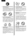
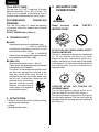
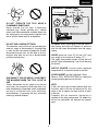
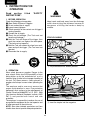
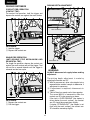
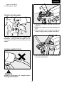
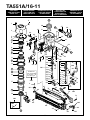
TA551A/16-11(CE)
PNEUMATIC STAPLER
PNEUMATISCHER HEFTER
AGRAFEUSE PNEUMATIQUE
AGGRAFFATRICE PNEUMATICA
MÁQUINA GRAPADORA NEUMÁTICA
OPERATING and MAINTENANCE MANUAL
BETRIEBSANLEITUNG
MANUEL D’UTILISATION et D’ENTRETIEN
MANUALE DI FUNZIONAMENTO E MANUTENZIONE
MANUAL DE OPERACIONES Y MANTENIMIENTO
WARNING
BEFORE USING THIS TOOL, STUDY THIS MANUAL TO ENSURE SAFETY WARNING AND
INSTRUCTIONS.
KEEP THESE INSTRUCTIONS WITH THE TOOL FOR FUTURE REFERENCE.
ACHTUNG
LESEN SIE VOR INBETRIEBNAHME DES GERÄTES DIE GEBRAUCHS- UND SICHERHEITSHINWEISE. BITTE BEWAHREN SIE DIE GEBRAUCHS- UND SICHERHEITSHINWEISE AUF,
DAMIT SIE AUCH SPÄTER EINGESEHEN WERDEN KÖNNEN.
AVERTISSEMENT
AVANT D’UTILISER CET OUTIL, LIRE CE MANUEL ET LES CONSIGNES DE SECURITE
AFIN DE GARANTIR UN FONCTIONNEMENT SUR.
CONSERVER CE MANUEL EN LIEU SUR AVEC L’OUTIL AFIN DE POUVOIR LE
CONSULTER ULTERIEUREMENT.
ATTENZIONE
PRIMA DI USARE QUESTA MACCHINA, STUDIARE IL MANUALE PER PRENDERE ATTO
DEGLI AVVERTIMENTI E DELLE ISTRUZIONIPER LA SICUREZZA.
TENERE QUESTE ISTRUZIONI INSIEME ALLO STRUMENTO PER CONSULTAZIONI FUTURE.
ATENCIÓN
PARA EVITAR GRAVES DAÑOS PERSONALES O EN LA PROPIEDAD.
ANTES DE EMPLEAR LA HERRAMIENTA, LEER CON ATENCIÓN Y COMPRENDER LOS
SIGUIENTES INSTRUCCIONES DE SEGURIDAD.
INDEX
INHALTSVERZEICHNIS
INDEX
3
INDICE
ENGLISH
Page
DEUTSCH
Page 15 to 26 Page
INDICE
to 14 Page
FRANÇAIS Page 27 to 38 Page
ITALIANO
Page 39 to 50 Page
ESPAÑOL
Page 51 to 62 Page
DEFINITIONS OF SIGNAL WORDS
WARNING:
Indicates a potentially hazardous situation which, if not avoided, could result in death
or serious injury.
CAUTION:
Indicates a potentially hazardous situation which, if not avoided, may result in minor or
moderate injury.
NOTE:
Emphasizes essential information.
DEFINITIONEN DER HINWEISBEZEICHNUNGEN
ACHTUNG!
Zeigt eine eventuell gefährliche Situation an, die den Tod oder schwere Verletzungen
zur Folge haben könnte, wenn sie nicht vermieden wird.
VORSICHT!
Zeigt eine eventuell gefährliche Situation an, die leichte oder mittelschwere
Verletzungen zur Folge haben könnte, wenn sie nicht vermieden wird.
HINWEIS:
Hebt wichtige Informationen hervor.
DÉFINITIONS DES DIFFÉRENTS DEGRÉS D’ AVERTISSEMENTS
AVERTISSEMENT Indique une situation éventuellement dangereuse qui, si elle n’est pas contournée,
pourrait provoquer la mort ou des blessure sérieuses.
ATTENTION
Indique une situation éventuellement dangereuse qui, si elle n’est pas contournée,
pourrait provoquer des blessures légères à moyennement sérieuses.
REMARQUE
Souligne des informations importantes.
DEFINIZIONE DELLE INDICAZIONI DI AVVERTIMENTO
ATTENZIONE:
Indica l’eventualità che possa verificarsi una situazione pericolosa, la quale se non
viene evitata, può risultare letale o provocare gravi lesioni.
AVVERTENZA:
Indica l’eventualità che possa verificarsi una situazione pericolosa, la quale se non
viene evitata, può provocare lesioni di lieve o media entità.
NOTA:
Evidenzia informazioni importanti.
DEFINICIÓN DE LAS INDICACIONES DE ADVERTENCIA
¡ATENCIÓN!
Indica una situación potencialmente peligrosa que podría causar la muerte o graves
lesiones si no se evita.
¡PRECAUCIÓN!
Indica una situación potencialmente peligrosa que podría causar lesiones menos
graves o leves si no se evita.
NOTA:
Resalta informaciones importantes.
2
ENGLISH
OPERATING and MAINTENANCE MANUAL
INDEX
1. SAFETY INSTRUCTIONS …………………………………………… 3
2. SPECIFICATIONS & TECHNICAL DATA ……………………………… 7
3. AIR SUPPLY AND CONNECTIONS …………………………………… 8
4. INSTRUCTIONS FOR OPERATION …………………………………… 10
5. MAINTENANCE ……………………………………………………… 14
6. STORAGE ……………………………………………………………… 14
7. TROUBLESHOOTING/REPAIRS ……………………………………… 14
BEFORE USING THIS TOOL, STUDY THIS MANUAL TO ENSURE SAFETY
WARNING
WARNING AND INSTRUCTIONS.
KEEP THESE INSTRUCTIONS WITH THE TOOL FOR FUTURE REFERENCE.
1. SAFETY INSTRUCTIONS
1. WEAR SAFETY GLASSES OR GOGGLES
Danger to the eyes always exists due to the
possibility of dust being blown up by the
exhausted air or of a fastener flying up due to
the improper handling of the tool. For these
reasons, safety glasses or goggles shall
always be worn when operating the tool.
The employer and/or user must ensure that
proper eye protection is worn. Eye protection
equipment must conform to the requirements
of Council Directive 89/686/EEC of 21 DEC.
1989 (the American National Standards
Institute, ANSI Z87.1) and provide both frontal
and side protection.
The employer is responsible to enforce the
use of eye protection equipment by the tool
operator and all other personnel in the work
area.
NOTE: Non-side shielded spectacles and
face shields alone do not provide adequate
protection.
WARNING
TO AVOID SEVERE PERSONAL INJURY OR
PROPERTY DAMAGE
BEFORE USING THE TOOL, READ
CAREFULLY AND UNDERSTAND THE
FOLLOWING “SAFETY INSTRUCTIONS”.
FAILURE TO FOLLOW WARNINGS COULD
RESULT IN DEATH OR SERIOUS INJURY.
PRECAUTIONS ON USING THE TOOL
3
ENGLISH
Thinner
Gasoline
2. EAR PROTECTION MAY BE REQUIRED IN
SOME ENVIRONMENTS
As the working condition may include
exposure to high noise levels which can lead
to hearing damage, the employer and user
should ensure that any necessary hearing
protection is provided and used by the
operator and others in the work area.
5. DO NOT OPERATE THE TOOL NEAR A
FLAMMABLE SUBSTANCE
Never operate the tool near a flammable
substance (e.g., thinner, gasoline, etc.).
Volatile fumes from these substances could
be drawn into the compressor and
compressed together with the air and this
could result in an explosion.
6. NEVER USE THE TOOL IN AN EXPLOSIVE
ATMOSPHERE
Sparks from the tool may ignite atmospheric
gases, dust or other combustible materials.
7. DO NOT USE A WRONG FITTINGS
The connector on the tool must not hold
pressure when air supply is disconnected. If a
wrong fitting is used, the tool can remain
charged with air after disconnecting and thus
will be able to drive a fastener even after the
air line is disconnected, possibly causing
injury.
3. DO NOT USE ANY POWER SOURCE
EXCEPT AN AIR COMPRESSOR
The tool is designed to operate on
compressed air. Do not operate the tool on
any other highpressure gas, combustible
gases (e.g., oxygen, acetylene, etc.) since
there is the danger of an explosion. For this
reason, absolutely do not use anything other
than an air compressor to operate the tool.
5
70
100
7
8. DISCONNECT THE AIR SUPPLY AND
EMPTY THE MAGAZINE WHEN THE TOOL
IS NOT IN USE
Always disconnect the air supply from the tool
and empty the magazine when operation has
been completed or suspended, when
unattended, moving to a different work area,
adjusting, disassembling, or repairing the tool,
and when clearing a jammed fastener.
4. OPERATE WITHIN THE PROPER AIR
PRESSURE RANGE
The tool is designed to operate within an air
pressure range of 5 to 7 bar (70 to 100 p.s.i.).
The pressure should be adjusted to the type
of the work being fastened. The tool shall
never be operated when the operating
pressure exceeds 8 bar (120 p.s.i.).
Never connect the tool to air pressure which
potentially exceeds 14 bar (200 p.s.i.) as the
tool can burst.
4
ENGLISH
12. USE SPECIFIED FASTENERS
(SEE PAGE 7)
The use of fasteners other than specified
fasteners will cause the tool malfunction. Be
sure to use only specified fasteners when
operating the tool.
9. INSPECT SCREW TIGHTNESS
Loose or improperly installed screws or bolts
cause accidents and tool damage when the
tool is put into operation. Inspect to confirm
that all screws and bolts are tight and
properly installed prior to operating the tool.
13. PLACE THE DISCHARGE OUTLET ON THE
WORK SURFACE PROPERLY
Failure to place the discharge outlet of the
nose in a proper manner can result in a
fastener flying up and is extremely
dangerous.
10. DO NOT TOUCH THE TRIGGER UNLESS
YOU INTEND TO DRIVE A FASTENER
Whenever the air supply is connected to the
tool, never touch the trigger unless you intend
to drive a fastener into the work. It is
dangerous to walk around carrying the tool
with the trigger pulled, and this and similar
actions should be avoided.
14. KEEP HANDS AND BODY AWAY FROM
THE DISCHARGE OUTLET
When loading and using the tool, never place
a hand or any part of body in fastener
discharge area of the tool. It is very
dangerous to hit the hands or body by
mistake.
11. NEVER POINT THE DISCHARGE OUTLET
TOWARD YOURSELF AND OTHER
PERSONNEL
If the discharge outlet is pointed toward
people, serious accidents may be caused
when misfiring. Be sure the discharge outlet
is not pointed toward people when connecting
and disconnecting the hose, loading and
unloading the fasteners or similar operations.
15. DO NOT DRIVE FASTENERS CLOSE TO
THE EDGE AND CORNER OF THE WORK
AND THIN MATERIAL
The workpiece is likely to split and the
fastener could fly free and hit someone.
5
ENGLISH
20. NEVER USE THE TOOL IF ANY PORTION
OF THE TOOL CONTROLS (e.g., TRIGGER,
CONTACT ARM) IS INOPERABLE,
DISCONNECTED, ALTERED OR NOT
WOKING PROPERLY
21. NEVER ACTUATE THE TOOL INTO FREE
SPACE
This will avoid any hazard caused by free
flying fasteners and excessive strain of the
tool.
16. DO NOT DRIVE FASTENERS ON TOP OF
OTHER FASTENERS
Driving fasteners on the top of other fasteners
may cause deflection fasteners which could
cause injury.
22. ALWAYS ASSUME THAT THE TOOL
CONTAINS FASTENERS
23. RESPECT THE TOOL AS A WORKING
IMPLEMENT
17. REMOVING THE FASTENERS AFTER
COMPLETING OPERATION
If fasteners are left in the magazine after the
completion of operation, there is the danger
of a serious accident occurring prior to the
resumption of operation, should the tool be
handled carelessly, or when connecting the
air fitting. For this reason, always remove all
fasteners remaining in the magazine after
completion of the operation.
24. NO HORSEPLAY
25. NEVER LOAD THE TOOL WITH
FASTENERS WHEN ANY ONE OF THE
OPERATING CONTROLS (e.g., TRIGGER,
CONTACT ARM) IS ACTIVATED
26. WEAR THE GLOVES DEPENDING ON THE
WORKING CONDITION
27. WHEN DISPOSING THE MACHINE OR ITS
PARTS, FOLLOW THE RELEVANT
NATIONAL RULES
18. CHECK OPERATION OF THE CONTACT
TRIP MECHANISM FREQUENTLY IN CASE
OF USING A CONTACT TRIP TYPE TOOL
Do not use the tool if the trip is not working
correctly as accidental driving of a fastener
may result. Do not interfere with the proper
operation of the contact trip mechanism.
OBSERVE THE FOLLOWING GENERAL
CAUTION IN ADDITION TO THE OTHER
WARNINGS CONTAINED IN THIS
MANUAL
• Do not use the tool as a hammer.
• Always carry the tool by the grip, never
carry the tool by the air hose.
• The tool must be used only for the purpose
it was designed.
• Never remove, tamper with the operating
controls (e.g., TRIGGER, CONTACT ARM)
• Keep the tool in a dry place out of reach of
children when not in use.
• Do not use the tool without Safety Warning
label.
• Do not modify the tool from original design
or function without approval by MAX CO.,
LTD.
19. WHEN USING THE TOOL OUTSIDE OR
ELEVATED PLACE
When fastening roofs or similar slanted
surface, start fastening at the lower part and
gradually work your way up. Fastening
backward is dangerous as you may lose your
foot place.
Secure the hose at a point close to the area
you are going to drive fasteners. Accidents
may be caused due to the hose being pulled
inadvertently or getting caught.
6
ENGLISH
2. SPECIFICATIONS AND TECHNICAL DATA
1. NAME OF PARTS
w
i
y
u
q
!1
q
w
e
r
t
y
u
i
o
!0
!1
Frame
Cylinder Cap
Contact Arm
Nose
Magazine
Trigger
Grip
Trigger Lock Dial
Staple Removal Lever
Pusher
Click Lever
r
o
e
!0
t
2. TOOL SPECIFICATIONS
PRODUCT NO.
TA551A/16-11 (CE)
HEIGHT
288.5 mm (11-3/8”)
WIDTH
84 mm (3-1/4”)
LENGTH
356 mm (14”)
WEIGHT
2.2 kg (4.9 lbs.)
RECOMMENDED
OPERATING PRESSURE
5 to 7 bar (70 to 100 p.s.i.)
LOADING CAPACITY
157 Staples
AIR CONSUMPTION
1.1R(0.039 ft3) at 7 bar (100 p.s.i.)
operating pressure
* The machine has been compactly designed in order to improve operating weight balance.
3. FASTENER SPECIFICATIONS
CROWN
PRODUCT NO.
TA551A/16-11 (CE)
CROWN
11 mm (7/16”)
LENGTH
25 to 51 mm (1˝ to 2”)
WIDTH
1.57 mm (0.062”)
THICKNESS
1.40 mm (0.055”)
GAUGE
16
LENGTH
THICKNESS
7
WIDTH
ENGLISH
TOOL AIR FITTINGS:
3. AIR SUPPLY AND
CONNECTIONS
This tool uses a 1/4˝ N.P.T. male plug. The inside
diameter should be 7mm (.28”) or larger. The
fitting must be capable of discharging tool air
pressure when disconnected from the air supply.
RECOMMENDED
PRESSURE:
OPERATING
WARNING
5 to 7 bar (70 to 100 p.s.i.). Select the operating
air pressure within this range for best fastener
performance.
DO NOT EXCEED 8 bar (120 p.s.i.).
Read section
INSTRUCTIONS”.
titled
“SAFETY
4. TECHNICAL DATA
q NOISE
A-weighted single-event sound power level
------ LWA, 1s, d 93.78 dB
A-weighted single-event emission sound
pressure level at work station
------- LpA, 1s, d 86.64 dB
These values are determined and documented
in accordance to EN12549 : 1999.
DO NOT USE ANY POWER SOURCE EXCEPT
AN AIR COMPRESSOR
The tool is designed to operate on compressed
air. Do not operate the tool on any other
highpressure gas, combustible gases (e.g.,
oxygen, acetylene, etc.) since there is the danger
of an explosion. For this reason, absolutely do not
use anything other than an air compressor to
operate the tool.
w VIBRATION
Vibration characteristic value = 3.6 m/s2
These values are determined and documented
in accordance to ISO 8662-11.
This value is a tool-related characteristic value
and does not represent the influence to the
hand-arm-system when using the tool. An
influence to the hand-arm-system when using
the tool will, for example, depend on the
gripping force, the contact
pressure force, the working
direction, the adjustment of
mains supply, the workpiece,
the workpiece support.
5
70
100
7
OPERATE WITHIN THE PROPER AIR
PRESSURE RANGE
The tool designed to operate within an air
pressure range of 5 to 7 bar (70 to 100 p.s.i.).
The pressure should be adjusted to the type of
the work being fastened. The tool shall never be
operated when the operating pressure exceeds 8
bar (120 p.s.i.).
5. APPLICATIONS
*General constuction works including siding,
decking, panel sheathing
*Crating
*Making wooden pallets
8
ENGLISH
[AIR SUPPLY & CONNECTIONS]
Regulator
Air compressor
Air filter
Oiler
Thinner
Gasoline
Air hose
DO NOT OPERATE THE TOOL NEAR A
FLAMMABLE SUBSTANCE
Never operate the tool near a flammable
substance (e.g., thinner, gasoline, etc.). Volatile
fumes from these substances could be drawn into
the compressor and compressed together with
the air and this could result in an explosion.
3-piece airset
Used at 5 to 7 bar (70 to 100 p.s.i.)
DO NOT USE A WRONG FITTINGS
The connector on the tool must not hold pressure
when air supply is disconnected. If a wrong fitting
is used, the tool can remain charged with air after
disconnecting and thus will be able to drive a
fastener even after the air line is disconnected,
possibly causing injury.
FITTINGS: Install a male plug on the tool which is
free flowing and which will release air pressure
from the tool when disconnected from the supply
source.
HOSES: Hose has a min. ID of 6 mm (1/4”) and
max. length of no more than 5 meters (17”).
The supply hose should contain a fitting that will
provide “quick disconnecting” from the male plug
on the tool.
SUPPLY SOURCE: Use only clean regulated
compressed air as a power source for the tool.
3-PIECE AIRSET (Air filter, Regulator, Oiler):
Refer to TOOL SPECIFICATIONS for setting the
correct operating pressure for the tool.
DISCONNECT THE AIR SUPPLY AND EMPTY
THE MAGAZINE WHEN THE TOOL IS NOT IN
USE
Always disconnect the air supply from the tool
and empty the magazine when operation has
been completed or suspended, when unattended,
moving to a different work area, adjusting,
disassembling, or repairing the tool, and when
clearing a jammed fastener.
NOTE:
A filter will help to get the best performance and
minimum wear from the tool because dirt and
water in the air supply are major causes of wear
in the tool.
Frequent, but not excessive, lubrication is
required for the best performance. Oil added thru
the air line connection will lubricate the internal
parts.
9
ENGLISH
4. INSTRUCTIONS FOR
OPERATION
Read section
INSTRUCTIONS”.
titled
“SAFETY
WARNING
1. BEFORE OPERATION
Check the following prior operation.
q Wear Safety Glasses or Goggles.
w Do not connect the air supply.
e Inspect screw tightness.
r Check operation of the contact arm & trigger if
moving smoothly.
t Connect the air supply.
y Check the air-leakage. (The Tool must not
have the air-leakage.)
u Hold the Tool with finger-off the trigger, then
push the contact arm against the work-piece.
(The tool must not operate.)
i Hold the Tool with contact arm free from workpiece and pull the trigger. (The Tool must not
operate.)
o Disconnect the air supply.
Keep hands and body away from the discharge
outlet when driving the fasteners because of
dangerous of hitting the hands or body by
mistake.
STAPLE LOADING
Pusher
WARNING
q Pull pusher back into “locked” position.
2. OPERATION
Wear safety glasses or goggles. Danger to the
eyes always exists due to the possibility of dust
being blown up by the exhausted air or of a
fastener flying up due to the improper handling of
the tool. For these reasons, safety glasses or
goggles shall always be worn when operating the
tool.
The employer and/or user must ensure that
proper eye protection is worn. Eye protection
equipment must conform to the requirements of
Council Directive 89/686/EEC of 21 DEC. 1989
(the American National Standards Institute, ANSI
Z87.1) and provide both frontal and side
protection.
The employer is responsible to enforce the use of
eye protection equipment by the tool operator and
all other personnel in the work area.
NOTE: Non-side shielded spectacles and face
shields alone do not provide adequate protection.
Staples
Magazine
w Insert the staples into the magazine.
10
ENGLISH
Click lever
CONTACT TRIP
Identified by BLACK TRIGGER.
SEQUENTIAL TRIP
The Sequential Trip requires the operator to hold
the tool against the work before pulling the trigger.
This makes accurate fastener placement easier,
for instance on framing, toe nailing and crating
applications. The Sequential Trip allows exact
fastener location without the possibility of driving
a second fastener on recoil, as described under
“Contact Trip”.
The Sequential Trip Tool has a positive safety
advantage because it will not accidentally drive a
fastener if the tool is contacted against the workor anything else-while the operator is holding the
trigger pulled.
e Hold the click lever and put back the pusher.
TEST OPERATION
q Adjust the air pressure at 5 bar (70 p.s.i.) and
connect the air supply.
w Without touching the trigger, depress the
contact arm against the work-piece.
Pull the trigger. (The tool must fire the
fastener.)
e With the tool off the work-piece, pull the
trigger.
Then depress the contact arm against the
work-piece. (The tool must fire the fastener.)
r Adjust the air pressure as much as the lowest
possible according the length of fastener and
the hardness of work-piece.
MODEL IDENTIFICATION
SEQUENTIAL TRIP
Identified by ORANGE TRIGGER.
CONTACT TRIP
The common operating procedure on “Contact
Trip” tools is for the operator to contact the work
to actuate the trip mechanism while keeping the
trigger pulled, thus driving a fastener each time
the work is contacted. This will allow rapid
fastener placement on many jobs, such as
sheathing, decking and pallet assembly.
All pneumatic tools are subject to recoil when
driving fasteners. The tool may bounce, releasing
the trip, and if unintentionally allowed to recontact
the work surface with the trigger still actuated
(finger still holding trigger pulled) an unwanted
second fastener will be driven.
11
ENGLISH
DRIVING FASTENERS
DRIVING DEPTH ADJUSTMENT
CONTACT FIRE OPERATION
(CONTACT TRIP)
For contact fire operation, hold the trigger and
depress the contact arm against the work surface.
1
Hex. bar wrench
2
PROCEDURE
q Hold the trigger.
w Depress the contact arm.
Screw M5×6
Up
SINGLE FIRE OPERATION
(ANTI-DOUBLE FIRE MECHANISM AND
SEQUENTIAL TRIP)
For single fire operation, depress the contact arm
against the work surface and pull the trigger. Tool
can not fire a second fastener until the trigger is
released and tool can cycle.
Contact arm “B”
Down
WARNING
ALWAYS disconnect air supply before making
adjustment.
2
The driving depth adjustment is made by
adjusting the contact arm “B”.
q With air pressure set, drive a few staples into a
representative material sample to determine if
adjustment is necessary.
w If adjustment is required, disconnect air
supply.
e Take off hex. bar wrench set in the magazine.
The screw M5×6 is loosened to allow the
contact arm “B” to be moved up or down.
If the tool is “OVER DRIVING” (the staples is
driven below the work surface), the contact
arm “B” should be moved down slightly.
If staples “STICKING-OUT” (the staples is not
flush with the work surface), the contact arm
“B” should be moved up slightly.
1
PROCEDURE
q Depress the contact arm.
w Pull the trigger.
12
ENGLISH
Tighten screw M5×6.
r Reconnect air supply.
TRIGGER LOCK MECHANISM
q Take out the staples from the inside of the
magazine.
w Release the staple removal lever and open the
door.
e Remove staples that are jammed inside the
nose by using a punch or slotted screw driver.
(UNLOCK)
Trigger lock
dial
(LOCK)
Staple removal lever
Trigger
The tool is equipped with a trigger lock
mechanism. Push and rotate the trigger LOCK to
the trigger UNLOCK position before driving
staples.
CLEARING JAMMED STAPLES
r After removing the staples. Close the door and
the staple removal lever.
WARNING
ALWAYS disconnect air supply before
clearing jammed fastener.
13
ENGLISH
5. MAINTENANCE
6. STORAGE
q ABOUT PRODUCTION YEAR
This product bears production number at the
lower part of the grip of the main body. The
two digits of the number from left indicates the
production year.
q When not in use for an extended period, apply
a thin coat of the lubricant to the steel parts to
avoid rust.
w Do not store the tool in a cold weather
environment. Keep the tool in a warm area.
e When not in use, the tool should be stored in a
warm and dry place. Keep out of reach of
children.
r All quality tools will eventually require servicing
or replacement of parts because of wear from
the normal use.
(Example)
08826035D
Year 2008
w DO NOT FIRE THE STAPLER WHEN IT IS
EMPTY
e USE A 3-PIECE AIRSET
Failure to use a 3-piece airset allows the
moisture and dirt inside compressor to pass
into the tool directly. This causes rust and
wear, and results in a poor operating
performance. The hose length between airset
and tool should be no longer than 5 m since a
longer length results in a reduction in air
pressure.
7. TROUBLE
SHOOTING/REPAIRS
The troubleshooting and/or repairs shall be
carried out only by the MAX CO., LTD. authorised
distributors or by other specialists.
r USE RECOMMENDED OIL
The velocite or turbine oil should be used to
lubricate the tool. Upon completion of
operations, place 2 or 3 drops of oil into the air
plug inlet with the jet oiler. (Recommended Oil
: ISO VG32)
t INSPECT AND MAINTAIN DAILY OR
BEFORE OPERATION
Supplement to the operating instruction
According to the European Norm EN 792-13 the
regulation is valid from 01.01.2001 that all
fastener driving tools with contact actuation must
be marked with the symbol “Do not use on
scaffoldings, ladders” and they shall not be used
for specific application for example:
WARNING
Disconnect air supply and empty the
magazine when inspecting or maintaining the
tool.
(1) Drain air line filter and compressor
(2) Keep lubricator filled in air 3-pieces set
(3) Clean filter element of air 3-pieces set
(4) Tighten all screws
(5) Keep contact arm moving smoothly
* when changing one driving location to another
involves the use of scaffoldings, stairs, ladders
or ladder alike constructions e.g. roof laths,
* closing boxes or crates,
* fitting transportation safety systems e.g. on
vehicles and wagons.
14
TA551A/16-11
EXPLODED
VIEW AND SPARE
PARTS LIST
EINZELTEILDARSTELLUNG UND
ERSATZEILLISTE
PNEUMATIC STAPLER
ESPLOSO DEI
COMPONENTI DE
ELENCO DELLE
PARTI DI RICAMBIO
SCHEMA ECLATE ET
LISTE DES PIECEC
DE RECHANGE
DESPIECE DE LA
MAQUINA Y LISTA
DE RECAMBIOS
A
3
1
20
24
2
47
B
46
45
21
33
32
5
6
7
25
29
44
23
31
8
22
9
30
10
28
42
27
7
B
26
34
11
40
48
36
12
35
37
13
38 39
15
O-RING KIT
16
Parts marked
are included
in the O-ring kit.
41
49
48
41
50
10
206
49
52
53
54
55
56
57
58
59
200
17
10
51
201
14
51
61
67
84
70
75
64
18
82
50
60
4
43
62
52
79
54
55
80
57
81
76
74
71
61
72
68
19
77
78
202
73
86
203
204
205
205
65
66
63
43
A
83
63
85
TA551A/16-11
ITEM
NO.
1
PART
MATERIAL
NO.
BB40470 Steel
SCREW M5x32
3
TA16996 Aluminum
CN35720 Polyethylene
terephthalate
4
FF31535
PARALLEL PIN 1535
2
Stainless steel
ENGLISH
DEUTSCH
FRANÇAIS
ITALIANO
ESPAÑOL
SCHRAUBE M5x32
VIS 5x32
VITE 5x32
TORNILLO M5x32
CYLINDER CAP
ZYLINDERDEKEL
COUVERCLE DE CYLINDRE
COPERCHIO CILINDRO
CUBIERTA DE CILINDRO
LABEL B (CE)
AUFKLEBER B (CE)
ÉTIQUETTE B (CE)
ETICHETTA B (CE)
ETIQUETA B (CE)
PARALLELBOLZEN 1535 GOUPILLE PARALLELE 1535
PERNO PARALLELO 1535
PERNO PARALELO 1535
GUARNIZIONE COPERCHIO
JUNTA CUBIERTA DE CILINDRO
CILINDRO
5
TA16997 Aluminum, Rubber CYLINDER CAP SEAL
DE COUVERCLE DE
ZYLINDERDECKELDICHCHTUNG JOINT
CYLINDRE
6
CN33838 Rubber
EXHAUST SEAL
AUSPUFFDICHTUNG
JOINT D’ÉCHAPPEMENT GUARNIZIONE DI SCARICO
SELLO DE EXTRACCIÓN
7
HH11170 Rubber
O-RING 1AP48
O-RING 1AP48
JOINT TORIQUE 1AP48 O-RING 1AP48
ANILLO TÓRICO 1AP48
8
CN37216 Polyacetal
HEAD VALVE GUIDE
DE LA SOUPAPE
DRUCKVENTILFÜRUNG GUIDAGE
PRINCIPALE
9
KK23934 Stainless steel
COMPRESSION SPRING 3934 DRUCKFEDER 3934
10
HH11138 Rubber
O-RING 1AP20
O-RING 1AP20
JOINT TORIQUE 1AP20 O-RING 1AP20
11
CN37217 Polyacetal
HEAD VALVE PISTON
KOPFVENTILKOLBEN
PISTON DE CLAPET DE TËTE
12
HH12108 Rubber
O-RING 1AG60
O-RING 1AG60
JOINT TORIQUE 1AG60 O-RING 1AG60
ANILLO TÓRICO 1AG60
13
CN35060 Polyacetal
CYLINDER RING
ZYLINDERRING
ANNEAU DE CYLINDRE ANELLO CILINDRO
ANILLO DE CILINDRO
14
CN34682 Urethane
CYLINDER SEAL
ZYLINDERDICHTUNG
JOINT DE CYLINDRE
15
HH19165 Rubber
O-RING 1A2.6x46.5
O-RING 1A2.6x46.5
JOINT TORIQUE 1A2.6x46.5 O-RING 1A2.6x46.5
16
CN35131 Rubber
CHECK VALVE
RÜCKSCHLAGVENTIL
CLAPET ANTI-RETOUR
VALVOLA DI NON RITORNO VÁLVULA DE RETENCIÓN
17
TA16998 Aluminum
CYLINDER
ZYLINDER
CYLINDRE
CILINDRO
18
HH11807 Rubber
O-RING 1AP38
O-RING 1AP38
JOINT TORIQUE 1AP38 O-RING 1AP38
19
TA70278 Magnesium, Steel MAIN PISTON UNIT
STANTUFFO
ARBEITSKOLBEN KOMPL. PISTON DE TRAVAIL COMPLET GRUPPO
OPERATORE
EMBOLO DE TRABAJO COMPL
20
TA17016 Rubber
BUMPER
STOSSDÄMPFER
AMORTISSEUR
AMMORTIZZATORE
AMORTIGUADOR
21
TA17017 Steel
NOZZLE
DÜSE
BUSE
UGELLO
TOBERA
22
TA18506 Aluminum
FRAME
GEHÄUSE
BOÎTIER
ALLOGGIAMENTO
CARCASA
23
TA81112
TA18515 Polyethylene
terephthalate
FRAME UNIT
GEHÄUSE KOMPL
BOÎTIER COMPLET
GRUPPO ALLOGGIAMENTO CARCASA COMP
24
LABEL “A”
TYPENSCHILD “A”
PRAQUE SIGNALÈTIQUE “A” TARGHETTA “A”
25
TA18516 Polyethylene
terephthalate
LABEL “B”
TYPENSCHILD “B”
PRAQUE SIGNALÈTIQUE “B” TARGHETTA “B”
PLACA DE CARACTERÍSTICAS “B”
26
TA18688 Steel
NOSE
NAGLERNASE
NEZ DE CLOUEUR
PICO DEL CLAVADOR
27
TA18523 Steel
WEAR CHIP
ABNUTZUNGSSPAN
COPEAU D’USURE
TRUCIOLO DI USURA
VIRUTA DE DESGASTE
28
AA22207 Steel
SCREW M4x5
SCHRAUBE M4x5
VIS M4x5
VITE 4x5
TORNILLO M4x5
29
TA18509 Steel
DRIVER GUIDE “B”
30
steel,
TA70256 Stainless
Steel
LATCH UNIT
VERSCHLUSS KOMPL
31
FF21275
ROLL PIN 4x16
ROLLENBOLZEN 4x16
32
TA18508 Steel
DRIVER GUIDE “A”
33
BB40465 Steel
SCREW M6x45
TOURILLON DE CYLINDRE 4x16 PERNO DI ROTOLAMENT 4x16 PERNO DE RODILLO 4x16
DE CHASSOR DE
NAGELTREIBERFÜHRUNG “A” GUIDAGE
GUIDA SPINGI-CHIODI “A” GUÍA CLAVADOR “A”
POINTES “A”
SCHRAUBE M6x45
VIS 6x45
VITE 6x45
TORNILLO M6x45
34
FF21611
ROLL PIN 3x32
ROLLENBOLZEN 3x32
35
CN35074 Nylon
TRIGGER LOCK DIAL
36
KK23507 Stainless steel
COMPRESSION SPRING 3507 DRUCKFEDER 3507
RESSORT À PRESSION 3507
MOLLA DI COMPRESSIONE 3507 MUELLE DE COMPRESIÓN 3507
37
TA17007 Steel
CONTACT ARM A
KONTAKTARM “A”
BARRE DE CONTACT A
BRACCIO DI CONTATTO “A” BRAZO DE CONTACTO “A”
38
TA17008 Steel
CONTACT ARM B
KONTAKTARM “B”
BARRE DE CONTACT B
BRACCIO DI CONTATTO “B” BRAZO DE CONTACTO “B”
39
BB40467 Steel
SCREW M5x6
SCHRAUBE M5x6
VIS M5x6
40
TA17001 Nylon
CONTACT ARM GUIDE
DE LA BARRE DE
KONTAKTARMFÜHRUNG GUIDE
CONTACT
41
KK23807 Stainless steel
COMPRESSION SPRING 3807 DRUCKFEDER 3807
RESSORT À PRESSION 3807
MOLLA DI COMPRESSIONE 3807 MUELLE DE COMPRESIÓN 3807
42
KK23282 Stainless steel
COMPRESSION SPRING 3282 DRUCKFEDER 3282
RESSORT À PRESSION 3282
MOLLA DI COMPRESSIONE 3282 MUELLE DE COMPRESIÓN 3282
43
CC49409 Steel
NUT M5 “T”
ECROU M5 “T”
44
CN35075 Nylon
TRIGGER LOCK LEVER
Steel
Steel
RESSORT À PRESSION 3934
GUIDA DELLA VALVOLA
PRINCIPALE
GUÍA DELA VÁLVULA PRINCIPAL
MOLLA DI COMPRESSIONE 3934 MUELLE DE COMPRESIÓN 3934
STANTUFFO VALVOLA DI
MANDATA
ANILLO TÁRICO 1AP20
EMBORO VÁLVULA DEL CABEZAL
GUARNIZIONE DEL CILINDRO SELLO DEL CILINDRO
PUNTA SPARACHIODI
ANILLO TÓRICO 1A2.6x46.5
CILINDRO
ANILLO TÓRICO 1AP38
PLACA DE CARACTERÍSTICAS “A”
DE CHASSOR DE
NAGELTREIBERFÜHRUNG “B” GUIDAGE
GUIDA SPINGI-CHIODI “B” GUÍA CLAVADOR “B”"
POINTES “B”
FERMETURE COMPLET GRUPPO CHIUSURA
CIERRE COMP
TOURILLON DE CYLINDRE 3x32 PERNO DI ROTOLAMENT 3x32 PERNO DE RODILLO 3x32
DE BLOCAGE DE LA
DE
BETÄTIGUNGSSPERREKNOPF DISQUE
DISCO DI SICURA GRILLETTO DISCO,BLOQUE
COMMANDE
ACCIONAMIENTO
MUTTER M5 “T”
VITE 5x6
TORNILLO M5x6
GUIDA BRACCIO DI CONTATTO GUÍA BRAZO DE CONTACTO
DADO M5 “T”
DE BLOCAGE DE LA
BETÄTIGUNGSSPERREHEBEL LEVIER
LEVA DI SICURA GRILLETTO
COMMANDE
TUERCA M5 “T”
PALANCA,BLOQUEO DE
ACCIONAMIENTO
45
TA17032 Aluminum
END CAP
ABSCHLUSSKAPPE
CAPOT DE RECOUVREMENT CAPPUCCIO DI CHIUSURA CAPERUZA DE CIERRE
46
HH12118 Rubber
O-RING 1AG35
O-RING 1AG35
JOINT TORIQUE 1AG35 O-RING 1AG35
47
TA17024 Nylon
FILTER “A”
FILTER “A”
FILTRE “A”
48
HH11125 Rubber
O-RING 1AP12
O-RING 1AP12
JOINT TORIQUE 1AP12 O-RING 1AP12
49
CN31323 Polyacetal
DE SOUPAPE DE ALLOGGIAMENTO VALVOLA CARCASA VÀLVULA DE
TRIGGER VALVE HOUSING BETÄTIGUNGSVENTILGEHÄUSE CHAPELLE
COMMANDE
DI AZIONAMENTO
ACCIONNAMIENTO
50
HH11119 Rubber
O-RING 1AP6
O-RING 1AP6
JOINT TORIQUE 1AP6
64
FILTRO “A”
O-RING 1AP6
ANILLO TÓRICO 1AG35
FILTRO “A”
ANILLO TÓRICO 1AP12
ANILLO TÓRICO 1AP6
TA551A/16-11
ITEM PART
MATERIAL
NO.
NO.
51
HH11209 Rubber
ENGLISH
DEUTSCH
FRANÇAIS
O-RING 1BP7
O-RING 1BP7
JOINT TORIQUE 1BP7
ITALIANO
O-RING 1BP7
ESPAÑOL
ANILLO TÓRICO 1BP7
52
FF30161
STRAIGHT PIN 161
ZYLINDERSTIIFT 161
GOUPILLE CYLINDRIQUE 161 SPINA CILINDRICA 161 PASADOR CILÍNDRICO 161
53
CN31589 Polyacetal
PILOT VALVE
STEUERVENTIL
VANNE-PILOTE
VALVOLA DI COMANDO VÁLVULA DE CONTROL
54
HH11113 Rubber
O-RING 1AP9
O-RING 1AP9
JOINT TORIQUE 1AP9
O-RING 1AP9
55
KK24123 Stainless steel
COMPRESSION SPRING 4123 DRUCKFEDER 4123
56
CN35779 Steel
TRIGGER VALVE STEM
DE SOUPAPE DE
BETÄTIGUNGSVENTILSCHAFT TIGE
COMMANDE
57
HH11901 Rubber
O-RING 1B1.4x2.5
O-RING 1B1.4x2.5
58
CN33009 Polyacetal
TRIGGER VALVE CAP
DE SOUPAPE
BETÄTIGUNGSVENTILDECKEL CAPUCHON
DE COMMANDE
COPERCHIO VALVOLA DI
AZIONAMENTO
CAPERUZA VÁLVULA DE
ACCIONAMIENTO
59
CN35115 Steel
CONTACT LEVER
KONTAKTHEBEL
LEVA DI CONTATTO
PALANCA DE CONTACTO
60
CN35714 Polyacetal
TRIGGER
BETÄTIGUNGSHEBEL
LEVIER DE COMMANDE GRILLETTO
PALANCA DE ACCIONAMIENTO
61
FF22402
ROLL PIN 3x16
ROLLENBOLZEN 3x16
TOURILLON DE CYLINDRE 3x16 PERNO DI ROTOLAMENT 3x16
PERNO DE RODILLO 3x16
62
TA18511 Steel
PUSHER
NAGELSCHIEBER
COULISSE A POINTES
DISPOSITIVO DI
AVANZAMENTO CHIODI
EMPUJADOR DE CLAVO
63
TA18512 Steel
CLICK LEVER
SPERRHEBEL
LEVIER BLOCAGE
LEVA DI ARRESTO
PALANCA DE BLOQUEO
64
KK44023 Stainless steel
PUSHER SPRING 4023
SCHIEBERFEDER 4023
DISPOSITIVO DI
RESSORT DE COULISSE 4023 MOLLA
AVANZAMENTO 4023
RESORTE DEL EMPUJADOR. 4023
65
FF21613
ROLL PIN 6x20
ROLLENBOLZEN 6x20
TOURILLON DE CYLINDRE 6x20 PERNO DI ROTOLAMENT 6x20
PERNO DE RODILLO 6x20
66
TA18510 Nylon
MAGAZINE
MAGAZIN
MAGASIN
CARGADOR
67
TA17010 Nylon
MAGAZINE COVER
MAGAZINABDECKUNG
COUVERCLE DE MAGASIN COPERCHIO CARICATORE CUBIERTA CARGADOR
68
TA18514 Polyethylene
terephthalate
WARNING LABEL(USA) WARNSCHILD(USA)
68
TA18689 Polyethylene
terephthalate
WARNING LABEL(CE)
70
TT15401 Steel
HEX.BAR WRENCH 4
AVISADOR DE
PLAQUE D‘AVERTISSEMENT(USA) TARGHETTA AVVERTENZE (USA) RÓTULO
PELIGRO (USA)
AVISADOR DE
PLAQUE D‘AVERTISSEMENT(CE) TARGHETTA AVVERTENZE (CE) RÓTULO
PELIGRO (CE)
A TUBO PER DADI
LLAVE DE CABEZA HUECA
SECHSKANTSTECKSCHLÜSSEL 4 CLÉ HEXAGONALE MALE 4 CHIAVE
ESAGONALI 4
HEXAGONAL 4
71
BB40408 Steel
SCREW M5x14
SCHRAUBE M5x14
TA17013 Steel
TAIL HANGER
VIS 5x14
VITE 5x14
DI SOSPENSIONE
SCHWANZAUFHANGER SUSPENSION DE QUEUE STAFFA
POSTERIORE
TORNILLO M5x14
72
73
BB40401 Steel
SCREW M5x22
SCHRAUBE M5x22
TORNILLO M5x22
74
CN35648 Polyacetal
75
Polyethylene
TA81180 Nylon,
terephthalate
TRIGGER
BETÄTIGUNGSHEBEL
MAGAZINE COVER ASSY (USA) MAGAZINABDECKUNG
KOMPL (USA)
75
Polyethylene
TA81189 Nylon,
terephthalate
76
77
Stainless steel
Stainless steel
Stainless steel
ANILLO TÓRICO 1AP9
RESSORT ÀPRESSION 4123 MOLLA DI COMPRESSIONE 4123 MUELLE DE COMPRESIÓN 4123
STELO VALVOLA DI
AZIONAMENTO
JOINT TORIQUE 1B1.4x2.5 O-RING 1B2.4x2.5
LEVIER DE CONTACT
CARICATORE
VÁSTAGO VÁLVULA DE
ACCIONAMIENTO
ANILLO TÓRICO 1B1.4x2.5
WARNSCHILD(CE)
VIS 5x22
VITE 5x22
DISPOSITIVO DE
SUSPENSION DE COLA
LEVIER DE COMMANDE GRILLETTO
PALANCA DE ACCIONAMIENTO
MAGAZINE COVER ASSY (CE) MAGAZINABDECKUNG
KOMPL (CE)
COUVERCLE DE MAGASIN
COMPLET (USA)
COUVERCLE DE MAGASIN
COMPLET (CE)
CUBIERTA CARGADOR
COMP (USA)
CUBIERTA CARGADOR
COMP (CE)
KK33247 Stainless steel
TORSION SPRING 3247 TORSIONSFEDER 3247
RESSORT DE TORSION 3247 MOLLA DI TORSIONE 3247
TA16138 Steel
S.T.LEVER
78
KK33144 Stainless steel
TORSION SPRING 3144 TORSIONSFEDER 3144
79
CN33627 Polyacetal
PILOT VALVE
80
CN33723 Steel
TRIGGER VALVE STEM
STEUERVENTIL
VANNE-PILOTE
DE SOUPAPE DE
BETÄTIGUNGSVENTILSCHAFT TIGE
COMMANDE
81
CN31346 Polyacetal
TRIGGER VALVE CAP
DE SOUPAPE
BETÄTIGUNGSVENTILDECKEL CAPUCHON
DE COMMANDE
STELO VALVOLA DI
AZIONAMENTO
COPERCHIO VALVOLA DI
AZIONAMENTO
82
TA17023 Steel
CONTACT ARM A
KONTAKTARM “A”
BARRE DE CONTACT A
BRACCIO DI CONTATTO “A” BRAZO DE CONTACTO “A”
83
FF41599
STEP PIN 1599
STUFENBOLZEN 1599
BOULON À GRADINS 1599 PERNO SCALARE 1599
84
GN10424 Stainless steel
SPRING COLLAR
FEDERSSTELLRING
COLLIER DE RESSORT
85
KK23998 Stainless steel
COMPRESSION SPRING 3287 DRUCKFEDER 3287
RESSORT À PRESSION 3287 MOLLA DI COMPRESSIONE 3287 MUELLE DE COMPRESIÓN 3287
86
KK29015 Stainless steel
COMPRESSION SPRING 9015 DRUCKFEDER 9015
RESSORT À PRESSION 9015 MOLLA DI COMPRESSIONE 9015 MUELLE DE COMPRESIÓN 9015
200
TA81012
O-RING KIT
O-RING KIT
TROUSSE DE JOINTS TORIQUES KIT DEGLI ANELLIIN “O” KIT DELOS ANILLOS TORICOS
201
TA81178
TRIGGER VALVE KIT
ABZUG-VENTIL-KIT
202
TA81011
SEQUENTIAL TRIP KIT
SEQUENTIELLE
SHUSSAUSLÖSUNG
TROUSSE DE SOUPAPE DE
COMMANDE
DECLENCHEMENT DE TIR
SEQUENTIEL
203
TA81014
STEP PIN KIT
SCHRITSTIFT-KIT
KIT DE GOUPILLE DE PAS CORRED DI PERNO DI PASSO KIT DE PERNO DE PASO
Steel
HEBEL (SEQUENTIELLE
SCHUßAUSLÖSUNG)
LEVIER (DÉCLENCHEMENT
DE TIR SÉQUENTILE)
UNITÁ DEL COPERCHIO
CARICATORE (USA)
UNITÁ DEL COPERCHIO
CARICATORE (CE)
LEVA (AZIONAMENTO
SEQUENZIALE)
RESSORT DE TORSION 3144 MOLLA DI TORSIONE 3144
MUELLE DE TORSIÒN 3247
PLANCA (DISPARO SECUENCIAL)
MUELLE DE TORSIÒN 3144
VALVOLA DI COMANDO VÁLVULA DE CONTROL
VÁSTAGO VÁLVULA DE
ACCIONAMIENTO
CAPERUZA VÁLVULA DE
ACCIONAMIENTO
PERNO ESCALONADO 1599
COLLARE DELLA MOLLA COLLAR DE MUELLE
DE LA VÁLVULA DE
KIT DELLA VALVOLÁ DI MANDO KIT
ACCIONAMIENTO
AZIONAMENTO SEQUENZIALE DISPARO SECUENCIAL
204
FF41842
205
EE39609 Urethane
BOULON À GRADINS 1842 PERNO SCALARE 1842 PERNO ESCALONADO 1842
STUFENBOLZEN 1842
DE CAOUTCHOUC
RUBBER WASHER 1.8x6x2 GUMMISCHEIBE 1.8x6x2 DISQUE
RONDELLA IN GOMMA 1.8x6x2 ARANDELO DE CAUCHO 1.8x6x2
1.8x6x2
206
CN80150
DE SOUPAPE DE
TRIGGER VALVE KIT (ST) ABZUG-VENTIL-KIT (ST) TROUSSE
COMMANDE (ST)
Steel
STEP PIN 1842
65
KIT DELLA VALVOLÁ DI
MANDO (ST)
KIT DE LA VÁLVULA DE
ACCIONAMIENTO (ST)
Recycled paper is used for this manual and its recyclable.
• The content of this manual might be changed without notice for improvement.
• Änderungen der Betriebsanleitung zum Zwecke der Verbesserung ohne Ankündigung
vorbehalten.
• Le contenu de ce manuel est sujet à modification sans préavis à des fins
d’amélioration.
• I contenuti di questo manuale possono essere cambiati senza preavviso per motivi di
miglioramento del prodotto.
• El contenido de este manual puede ser cambiado sin noticia previa para mejoramiento.
• The specifications and design of the products in this manual will be subject to change without
advance notice due to our continuous efforts to improve the quality of our products.
• Änderungen bei technischen Daten und Design der Produkte in diesem Handbuch im Sinne der
Produktverbesserung bleiben vorbehalten.
• Les caractéristiques et la conception des produits mentionnés dans ce manuel sont sujettes à
des modifications sans préavis en raison de nos efforts continus pour améliorer la qualité de nos
produits.
• Le caratteristiche e la concezione dei prodotti menzionati in questo manuale sono soggette a
modifiche senza preavviso a causa dei nostri sforzi continui per migliorare la qualità dei nostri
prodotti.
• Las características y la concepción de los productos mencionados en este manual están sujetas
a modificaciones sin preaviso debido a nuestros esfuerzos continuos para mejorar la calidad de
nuestros productos.
OSTSTRASSE 22, 40211
DÜSSELDORF, GERMANY
TEL: +49-211-9365300
FAX: +49-211-93653017
Camerastraat 19
1322 BB Almere The Netherlands
Phone: +31-36-546-9699
FAX: +31-36-536-3985
www.max-ltd.co.jp/int/ (GLOBAL Site)
www.max-europe.com (EUROPE Site)
★080306-00/02
PRINTED IN JAPAN
GEDRUCKT IN JAPAN
IMPRIMÉ AU JAPON
STAMPATO IN GIAPPONE
IMPRESO EN JAPÓN
![Stiftnagler SK 335- 201 C deutsch [1] Abmessungen:L = 254](http://vs1.manualzilla.com/store/data/006281873_1-8c943fec4e20e2e88c178e3bef799b9c-150x150.png)