1
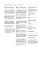
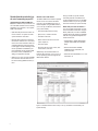
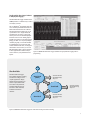
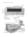
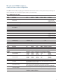
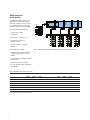
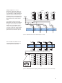
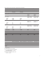
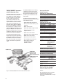
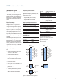
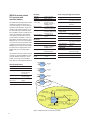
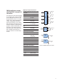
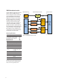
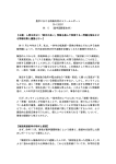
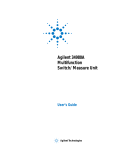
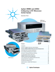
Agilent 34980A
Multifunction
Switch/Measure Unit
Data Sheet
Challenge the Boundaries of Test
Agilent Modular Products
High-performance switch/measure unit provides a
low-cost, highly flexible measurement platform
If you use automated test equipment for
design validation or manufacturing, you now
have a cost-effective solution for many test
system applications. The 34980A multifunction switch/measure unit provides functionality that is easy to set up and use, with
a fast startup time. The 34980A helps you
lower your cost of test and accelerate your
test-system integration and development.
The 34980A handles system switching up
to 26.5 GHz and provides basic measurements and system control. It also offers
DMM measurements, counter/ totalizer functionality, digital I/O with pattern
capabilities, and analog outputs with basic
waveforms— all in one low-cost, compact
box. And with its standard connectors and
software drivers, computer-standard I/O,
and Web browser interface, the 34980A
easily integrates into electronic functional
test and data acquisition systems.
Flexible switching, measurements, and system control
The 34980A accommodates up to 8 plug-in
modules to give you the flexibility you need.
Choose from 21 different modules to define
your own configuration. You can buy what
you need now and add to it or reconfigure it
as your requirements change.
2
Whether you are measuring temperature,
AC or DC voltage, resistance, frequency,
current, or custom measurements, the
34980A offers the functionality you need
in a single box. Switch in different measurements with high-performance signal switching up to 300V with no external signal
conditioning required. Choose between
different switch types and topologies with
frequency ranges from DC to 26.5 GHz. The
34980A offers high-density multiplexers for
scanning multiple channels, matrices for
connecting multiple points at one time, and
general purpose switches for simple control
and high power needs.
The rugged instrument comes with
a variety of system-ready features:
• Webbrowserinterfaceshows
settings at a glance and provides remote
access and control
• Self-guidingfrontpaneltoconfigure,
troubleshoot or view data
• LowEMIandefficientsystem
cooling
• Heavy-dutycablingandconnection
options
• Flexiblerackmountingoptions
Use the 34980A to route individual signals
or monitor multiple signals over a specified
period of time—monitor a single channel or
multiple channels, set alarms, and identify
irregularities.
• Relaycountershelppredictendof-life
The 34980A offers flexible choices for
system control. You can control external
devices such as microwave switches,
attenuators, solenoids, and power relays. Or
use the digital inputs to sense limit-switch
and digital-bus status.
• DMMmeasurementaccuraciesinclude
the switch for simple
calculations
Optimized for test systems
The 34980A has the performance you need
for medium- to high-density switching/
measurement applications such as design
verification, functional test and data acquisition. Your signals are switched to the right
measurement device without compromising
signal integrity. Switch your signals to the
optional internal DMM and achieve optimal
throughput on switch closure time. Or, if
you prefer, you can easily connect to external instruments such as DMMs, scopes,
power supplies, and more. What’s more,
with the built-in Ethernet interface, you can
control the 34980A and collect data from
anywhere on the network. For a complete
modular solution, use the 34980A together
with PXI modular products when more
capability is required.
• In-rackcalibrationforreducedmaintenance time
Make system connections easily
and quickly with simple, reliable
connection options:
• Built-inEthernet,USB2.0,
andGPIBconnectivity
• Low-cost,standard50-or78-pinDsub
connectors and cables
• Detachableterminalblockswithstrain
relief
• Massinterconnectsolutions
In addition, the 34980A comes with Agilent
IOLibrariesSuite.Quicklyestablishan
error-free connection between your PC
and instruments—regardless of vendor.
TheIOLibrariesproviderobustinstrument
control and work with the software development environment you choose.
Easier signal routing with four
2-wire internal analog buses. You can route
your measurements directly to the internal DMM, or you can connect to external
instruments through the analog bus connector on the rear of the mainframe. And
since you have four 2-wire buses, you can
dedicate one bus for use with the internal
DMM and use the other three buses for
module extensions or additional signal routing between modules, reducing your wiring
needs.
You can define up to 500 switch sequences
to control complex signal routing and
the order of switch closures. Assign a
sequence, give it a name and then execute
it with the name you created.
Switch sequences are downloaded and
stored in the instrument for ease of programming and increased throughput.
External trigger capabilities make it easy for
you to time and synchronize measurements
and other events. This can help you determine when to begin or end an acquisition.
Measurements you can trust
Get proven performance from Agilent
instruments, with the resolution, repeatability, speed, and accuracy you’ve come
to expect.
The 34980A offers built-in signal conditioning and modular flexibility. When you use it
with the internal DMM, you can configure
each channel independently for the measurements you choose. It includes a variety
of features that give you confidence in your
measurements:
• 6½digitsofresolutionwith.004%
of accuracy with DC voltage
measurements
• Alarmsperchannel—highlimit,
low limit, or both
• Mathfunctions—useMx+Bfor
custom linear conversions and
converting raw inputs
• Built-inthermocouplereference
for temperature measurements (34921T)
• Time-stampedreadings
• AddmoreformulaswithBenchLinkData
LoggerSoftware
The integrated DMM is mounted inside
the mainframe and does not consume
any of the eight user-available slots. You
can access the DMM through any switch
module that connects to the analog bus,
or directly from the analog bus connector
on the rear of the mainframe. The internal
DMM gives you the flexibility to measure
11 types of inputs:
• Temperaturewiththermocouples,RTDs,
or thermistors (with 34921A)
• DCandACvoltage
• 2-and4-wireresistance
• Frequencyandperiod
Modules provide flexible system
stimulus and control
System control—with analog outputs,
open-collector digital outputs, clock generation, and isolated Form-C relays for controlling external devices. Additionally, with the
microwave switch/attenuator driver, highfrequency switches and attenuators can be
efficiently controlled external to the 34980A
mainframe.
Analog sources—output either voltage or
current. You can configure the 4-channel
isolated D/A converter as a point-to-point
arbitrary waveform generator that lets you
define up to 500,000 points per waveform.
Digital patterns—send or receive digital
data from your device under test. With onboard memory you can output communication protocols and bit streams or monitor
digital input patterns and interrupt when a
user-defined pattern is detected.
• DCandACcurrent
You can control the DMM directly, or
configure it to work in conjunction with
the switches. Each switch channel can be
configured independently for measurement
functions, scale factors and alarm limits.
Advanced measurement features such as
offset compensation, variable integration
time, and delay are also selectable on a
per-channel basis.
The DMM inputs are shielded and optically isolated from the 34980A’s earthreferenced circuitry and computer interface,
and as a result, you get up to 300 V of input
isolation. This is important for reducing
ground-loops and common-mode voltage
errors associated with long wiring runs and
floating sources.
Simple DMM calibration is
accomplished with just the analog bus connection on the rear panel of the mainframe.
You don’t need to remove the mainframe
from the rack or dedicate a channel for
calibration.
3
Standard interfaces take the hassle out of connecting to your PC
Standard Ethernet, USB and GPIB interfaces are included in every mainframe. Use
one of the built-in interfaces that is already
available in your computer, or if you prefer,
GPIBisstillavailable.
• USBoffersthequickestandeasiestconnection scheme—it’s perfect for small
systems and bench connections.
• Ethernetoffershigh-speedconnections
that allow for remote access and control.
Choose a local area network to filter out
unwantedLANtrafficandspeedupthe
I/O throughput. Or take advantage of the
remote capabilities and distribute your
tests worldwide. Use the graphical Web
browser to monitor, troubleshoot, or
debug your application remotely.
• GPIBhasmanyyearsofprovenreliability
for instrument communication and can
beusedinexistingGPIBbasedtestsystems.
Remote access and control
The built-in Web browser interface provides
remote access and control of the instrument via a Java-enabled browser such as
Internet Explorer. Using the Web interface,
you can set up, troubleshoot, and maintain
your system remotely.
• Viewandmodifyinstrumentsetup
• Open,close,ormonitorswitches
• SendSCPIcommands
• Defineandexecuteswitchscansand
switch sequences
• Viewerrorqueue
• Getstatusreportsonrelaycounts,firmware revisions, and more
Additionally, since the Web interface is
built into the instrument, you can access it
on any operating system that supports the
Web browser without
having to install any special software.
PasswordprotectionandLANlockout
are also provided to limit access.The Web
interface makes it easy to set up, troubleshoot and maintain your system remotely.
Works with your choice of software so
you can save time and preserve your software and hardware investments. Program
directlywithSCPI,oruseIVIorLabVIEW
software drivers that provide compatibility
with the most popular development environments and tools:
• AgilentVEEPro,AgilentT&MToolkit
(requires Microsoft® Visual Studio®.
NET)
• NationalInstrumentsLabVIEW,
LabWindows/CVI,TestStand,and
Switch Executive
• MicrosoftVisualStudio.NET,C/C++and
VisualBasic6
Figure 1. The Web interface makes it easy to set up, troubleshoot and maintain your
system remotely
4
Free BenchLink Data Logger Software
to Simplify data logging
TheBenchLinkDataLoggersoftwareforthe
34980A provides a convenient way to collect
and analyze your data.
This is a Windows® -based application that
uses a familiar spreadsheet environment to
define measurement data to be collected.
The tab-based format makes it easy to set
up and initiate scans. Simply identify the
measurements you want to acquire, initiate the process and see the data displayed
real-time. The rich set of colorful graphics
provides many options for analyzing and displaying your data. You can specify multiple
channels per graph, or send collected data
to multiple graphs. Use strip charts with
markers and alarm indication, or histograms
with statistics. And of course you can use
BenchLinkDataLoggertoeasilymovedata
to other applications for further analysis,
or for inclusion in your presentations and
reports.
Figure 2. 34826A BenchLink Data Logger Software for high speed data logging with no
programming
Start
Also Available
Scan List A
(Base)
Event
•ControlInstruments
•SendNotification(s)
•StopScan
Eve
nts
Events
TheBenchLinkDataLogger
Pro Software adds limit checking
and decision making for more
complex applications. Simply
identify the measurements you
want to acquire, define limits
and actions to be preformed,
and then initiate the process.
Your data is then collocated,
evaluated and acted on
real-time.
Scan List B
Event
•ControlInstruments
•SendNotification(s)
•StopScan
nts
Eve
Scan List C
Event
•ControlInstruments
•SendNotification(s)
•StopScan
Figure 3. 34832A BenchLink Data Logger Pro adds limit checking and decision making
5
Power and flexibility to get your job done
Intuitive front panel with self-guiding menus
See results on bright,
multiline display
Store and
recall
instrument
setups
Set I/O,
date and
other system
features
6 1 ⁄ 2 digit DMM measurements
with 11 functions
Use keypad to enter channel number or knob to scroll
Configure measurements, manage
sequences, view errors and alarms
Scan multiple channels,
close specified channel list,
or monitor results on a single channel
Set up scan lists
Store up to 500,000 readings with timestamp
External trigger to synchronize events
Built-in Ethernet,
USB 2.0,
and GPIB
interfaces
8-slots connect to optional internal DMM
Standard DSub connector kits
Access to four
2-wire analog buses
Optional terminal blocks
21 plug-in modules to choose from
6
Industry standard DSub cables
Mix and match 34980A modules to
create your own custom configuration
The 34980A mainframe holds up to eight plug-in modules. Mix and match them to create a custom system to meet your switching and
system control needs. You can easily add or replace modules as your needs change.
Table 1. 34980A modules at a glance
Module
Description
Max
volts
Switch/Carry BW
current
(MHz)
Scan
ch/sec
Thermal
offset
± 300 V
1A/2A
100
< 3 uV
Comments
Multiplexer modules
34921A
40-channel armature multiplexer w/low
thermal offset
45 MHz
Temperature reference
4 current channels
Config as 2- or 4-wire
34922A
70-channelarmaturemultiplexer
±300V
1A/2A
25MHz
100
<3uV
Configas2-or4-wire
34923A
40/80-channel reed multiplexer
± 150 V
0.5A/1.5A
45 MHz
500
< 50 uV
Config as 1-, 2- or 4-wire
34924A
70-channelreedmultiplexer
±150V
0.5A/1.5A
25MHz
500
<50uV
Configas2-or4-wire
34925A
40/80-channel optically isolated
FET multiplexer
± 80 V
0.02A
1 MHz
1000
< 3 uV
Config as 1-, 2- or 4-wire
34931A
Dual4x8armaturematrix
±300V
1A/2A
30MHz
100
<3uV
Backplaneexpandable
34932A
Dual4x16armaturematrix
±300V
1A/2A
30MHz
100
<3uV
Backplaneexpandable
34933A
Dual/Quad4x8reedmatrix
±150V
0.5A/1.5A
30MHz
500
<50uV
Backplaneexpandable
Config as 1- or 2-wire
34934A
Quad4x32reedmatrix
+/-100V
0.5A/0.5A
20MHz
500
<50uV
R
owexpansionkit.
Config as 1- or 2-wire
Matrix modules
General-purpose modules
34937A
28-channelFormCand
4-channelFormA
+/-300V
1A/2A
+/-250VAC 5A
10MHz
N/A
<3uV
<3uV
34938A
20-channel5-ampFormA
+/-250VAC 5A/8A
1MHz
N/A
<3uV
34939A
64-channelsFormA
+/-100V
1A/2A
10MHz
N/A
<3uV
Isolation
Freq
range
VSWR
Input
impedence Comments
RF and microwave modules
Module
Description
Insertion
loss
34941A
Quad1x450ohm3GHzRFmultiplexer
0.6dB
>58dB
3GHz
<1.25
50Ω
@1GHz
34942A
Quad1x475ohm1.5GHzRFmultiplexer 0.6dB
>60dB
1.5GHz
<1.35
75Ω
@1GHz
34945A/
34945EXT
Microwave switch/attenuator driver
Can drive up to 64 external switch coils; 32 SPDT switches,8 multiport switches,
8 attenuators, or your own combination. Expand with additional 34945EXTs.
34946A
Dual1x2SPDTterminated
microwaveswitch
<0.42dB
<0.69dB
<0.8dB
>85dB
>67dB
>60dB
4GHzor
20GHz
26.5GHz
<1.15
<1.30
<1.6
50Ω
@4GHz
@20GHz
@26.5GHz
34947A
Triple1x2SPDTunterminated
microwaveswitch
<0.42dB
<0.69dB
<0.8dB
>85dB
>67dB
>60dB
4GHzor
20GHz
26.5GHz
<1.15
<1.30
<1.6
50Ω
@4GHz
@20GHz
@26.5GHz
System control modules
Description
34950A
64-bit digital I/O with memory
and counter
Eight 8-bit digital I/O channels with programmable polarity, thresholds up to 5 V,
with handshaking protocols and pattern memory. Two 10 MHz frequency counter and
programmable clock output to 20 MHz.
34951A
4-channel isolated D/A converter
with waveform memory
Output DC voltage up to ± 16 V or DC current up to ± 20 mA.
Output waveforms with a 200 kHz update rate and 16 bits of resolution.
Use on-board memory to create point-to-point waveforms with more than 500,000 points.
34952A
Multifunction module with 32-bit DIO,
2-ch D/A and totalizer
Four 8-bit digital I/O channels, two ± 12-V analog outputs, and a 100 kHz gated totalizer.
34959A
Breadboardmodule
Createyourowncustomdesignswithaccesstothe+12Vand+5Vsupplies,
16 GPIO ports and 28 relay drive lines.
7
34980A multiplexer
switch modules
H
The 34980A multiplexer modules can be
used to connect one of many different
points to a single point. You can connect
to an external instrument, or scan multiple analog signals to the internal DMM.
L
H
L
H
L
H
L
Analog Buses
ABus1
I
L
Current
041 L
I
Fuse
L
I
Fuse
043 L
I
Fuse
044 L
I
Fuse
042
Choose from the following features:
• 1-wire,2-wire,or4-wire
configurations
ABus2
DMM
(SENS)
DMM
(MEAS)
Current
931
H
L
H
921
H
• Highvoltage—upto300V,1A
L
H
L
923
922
ABus4
ABus3
H
L
924
L
021
026
031
036
022
027
032
037
023
028
033
038
024
029
034
COM 2
• Highdensity—702-wireor
80 1-wire channels
H
• Scanupto1000ch/secwiththe
34925A
025
039
H
H
L 030
L
035
H
L
040
L
Bank 2
• Bandwidthsupto45MHz
Figure 4. 34921A 40-channel armature multiplexer with low thermal offset (bank 2)
• Temperaturemeasurementswithbuiltin thermocouple reference junction
(34921T)
• ACorDCcurrentmeasurementswithout
external shunts
• Flexibleconnectionsviastandard
50-or78-pinDsubcablesordetachable
terminal blocks
Table 2. Multiplexer measurement functions
Voltage
AC/DC
Current
AC/DC
Ω 2-Wire
Ω 4-Wire
Thermocouple
RTD
2-Wire
RTD
4-Wire
Thermistor
Yes
34921A Armature Multiplexer
Yes
Yes
Yes
Yes
Yes
Yes
Yes
Yes
34922AArmatureMultiplexer
Yes
No
Yes
Yes
Yes
Yes
Yes
Yes
Yes
34923AReedMultiplexer(2-wire)
Yes
No
Yes
Yes
Yes
Yes
Yes
Yes
Yes
34923AReedMultiplexer(1-wire)
Yes
No
Yes
Yes
No
Yes
Yes
No
Yes
34924AReedMultiplexer
Yes
No
Yes
Yes
Yes
Yes
Yes
Yes
Yes
34925AFETMultiplexer(2-wire)
Yes
No
Yes
Yes
Yes
Yes
No
Yes
No
34925AFETMultiplexer(1-wire)
Yes
No
Yes
Yes
No
Yes
No
No
No
Note: See User’s Guide for additional information.
8
Freq/
Period
Multiple multiplexers can connect
to the built-in analog buses, allowing you
to scan up to 560 2-wire channels or 640
1-wire channels in a single mainframe. The
34921A also offers 4 channels for directly
measuring current. Or if you need more current channels, shunts can be added to the
terminal block for easy current measurements.
The multiplexer modules feature breakbefore-make connections to ensure that no
two signals are connected to each other
during a scan. Or, if you prefer, you can
control switching manually to create your
own switch configuration. All the multiplexer switches have a relay counter to help
predict when relays need to be replaced.
Bank 1
HD
001
COM 1
HD
LD
100 Ω
100 Ω
HD
LD
006
HD
LD
011
HD
LD
016
002
007
012
017
003
008
013
018
004
009
014
019
005
000
HD
015
LD
HD
LD
LD
020
HD
LD
HD
LD
100 Ω
100 Ω
100 Ω
100 Ω
HD
LD
HD
ABus1
DMM
(MEAS)
LD
Analog buses
914
913
912
911
HD
LD
HD
ABus2
DMM
(SENS)
LD
HD
LD
HD
ABus3
HD
LD
LD
ABus4
HD
LD
Figure 5. 34923A 40-channel reed multiplexer (bank 1 shown)
Note:The34923Aand34924Ahave100
ohm input protection resistors that limit
current and protect the reed relays.
Figure 6. 34925A 40/80-channel optically isolated FET mux (shown in 1-wire mode bank 2)
9
Table 3. Multiplexer selection table—specifications and characteristics
34921A
34922A
34923A
34924A
34925A
Channels/configurations
402-wire
20 4-wire
4-current
1.5 A Fused
702-wire
35 4-wire
801-wire
40 2-wire
20 4-wire
702-wire
35 4-wire
801-wire
40 2-wire
20 4-wire
Switch type
Armature latching
Armature
latching
Reed
Reed
Optically
isolated FET
Input characteristics (per channel)
Max volts
± 300 V
Maxcurrent(DC,ACRMS)
Switch current
Carry current
1A
2A
Power (W, VA)
[6]
[1]
± 300 V
1A
2A
[1]
± 150 V peak
[2]
± 150 V peak
0.5 A [5]/ 0.05 A [11]
[5]
[11]
1.5 A / 0.05 A
[2]
± 80 V peak
0.5 A [5]/ 0.05 A [11]
[5]
[11]
1.5 A / 0.05 A
[2]
0.02 A[8]
60 W
60 W
10 W
10 W
108
108
108
108
<1.5Ω
<1.5Ω
< 1.5 Ω /200 Ω
nominal
< 1.5 Ω /200 Ω nominal
<700Ω
< 3 uV
< 3 uV
< 50 uV
< 100 uV 1-wire
< 50 uV
< 3 uV
DCIsolation(ch-ch,ch-earth)
>10GΩ
>10GΩ
>10GΩ
>10GΩ
>10GΩ
Leakagecurrent N/A
N/A
N/A
N/A
20nA
<1°C
N/A
N/A
N/A
N/A
45 MHz
25 MHz
45 MHz /4 MHz
10 MHz 1-wire
25 MHz /4 MHz
-75dB
-75dB
-50dB
-40dB
-75dB
-75dB
-50dB
-75dB
-75dB
-50dB
-40dB
-75dB
-70dB
-45dB
Notrecommendedfor
RFsignalswitching
150pF
150pF
250pF
200pF
130pF
120pF
200pF
170pF
100pF
300pF(600pF1-wire)
Volt-Hertz limit
Initial closed channel res
[3][12]
[5]
[11]
1.6 W
107
[5]
[11]
General specifications
Offset voltage
[3]
[3]
T/C cold junction accuracy
[3, 10]
[9]
AC characteristics
Bandwidthatterminalblock
[4]
Crosstalk at terminal block (ch-ch)
300kHz
1MHz
20MHz
45MHz
Capacitance at terminal block
HI-LO
LO–earth
[5]
[5]
[11]
1 MHz
[4]
[1] DCorACRMSvoltage,channel-to-channelorchannel-to-earth
[2]
[3]
[4]
[5]
[6]
[7]
[8]
[9]
[10]
Peak voltage, channel-to-channel or channel-to-earth
Into analog bus. System errors are included in the internal DMM measurement accuracy specifications
50Ωsource,50Ωload,differentialmeasurementsverifiedwith4-portnetworkanalyzer(Sdd21)
Withinputresistorsbypassed.Bypassingresistorswillreducelifetimeofrelays.Seetheratedloadrelaylifecharacteristics.
Limitedto6Wofchannelresistancepowerlosspermodule
Speedsarefor2-wireohmsorDCV,41/2 digits, delay 0, display off, autozero off, and within bank
DC or peak AC current
Ambient temperature < 30°C
Includes 0.5°C temperature reference sensor and 0.5°C terminal block isothermal gradient error, measured under worst case loading of the mainframe; see User’s
Guide for information on supported external reference sensors
[11]Withinputprotectionresistors:2x100Ω±5%; 0.5W; TC=±200ppm/°C.Theseriesresistanceofthe34923/24/25limitstheuseofthe100Ωrange.
[12]Channelresistanceistypically<1.5Ωbutcangoashighas50Ωwhenachannelisusedinmeasurementapplicationswith<10mAloadcurrent.Increased
relay channel resistance for measurements with load currents below 10 mA can occur on cards that have been out of service or following relay inactivity for periods of greater than 1 week. Switching relays for 2K cycles prior to use may reduce the variation in channel resistance. Applies to the 34921A and 34922A. Agilent
recommendstheuseof4-wireOhmsforresistancemeasurements.Forhighaccuracyvoltagemeasurements,selecttheDMMinputresistancesettingof>10G
ohms to minimize the impact of relay contact resistance.
10
Table 3. Multiplexer selection table—specifications and characteristics—continued
34921A
34922A
34923A
34924A
34925A
100M
100M
1000M
1000M
10 M
10 M
10 M
10 M
100k
100k
10k
10k
UnlimitedwithinFET
banks
Unlimited within FET
banks
UnlimitedwithinFET
banks
General characteristics
Relaylife,typical
Noload
10 V, 100 ma
Ratedload
Scanning speeds
[7]
100 ch/sec
100 ch/sec
500 ch/sec
500 ch/sec
1000 ch/sec
Open/ close time, typical
4 ms/4 ms
4 ms/4 ms
0.5 ms/0.5 ms
0.5 ms/0.5 ms
0.25 ms/0.25 ms
Analog bus backplane connection
Yes
Yes
Yes
Yes
Yes
[1] DCorACRMSvoltage,channel-to-channelorchannel-to-earth
[2]
[3]
[4]
[5]
[6]
[7]
[8]
[9]
[10]
Peak voltage, channel-to-channel or channel-to-earth
Into analog bus. System errors are included in the internal DMM measurement accuracy specifications
50Ωsource,50Ωload,differentialmeasurementsverifiedwith4-portnetworkanalyzer(Sdd21)
Withinputresistorsbypassed.Bypassingresistorswillreducelifetimeofrelays.Seetheratedloadrelaylifecharacteristics.
Limitedto6Wofchannelresistancepowerlosspermodule
Speedsarefor2-wireohmsorDCV,41/2 digits, delay 0, display off, autozero off, and within bank
DC or peak AC current
Ambient temperature < 30°C
Includes 0.5°C temperature reference sensor and 0.5°C terminal block isothermal gradient error, measured under worst case loading of the mainframe; see User’s
Guide for information on supported external reference sensors
[11]Withinputprotectionresistors:2x100Ω±5%; 0.5W; TC=±200ppm/°C.Theseriesresistanceofthe34923/24/25limitstheuseofthe100Ωrange.
[12]Channelresistanceistypically<1.5Ωbutcangoashighas50Ωwhenachannelisusedinmeasurementapplicationswith<10mAloadcurrent.Increased
relay channel resistance for measurements with load currents below 10 mA can occur on cards that have been out of service or following relay inactivity for periods of greater than 1 week. Switching relays for 2K cycles prior to use may reduce the variation in channel resistance. Applies to the 34921A and 34922A. Agilent
recommendstheuseof4-wireOhmsforresistancemeasurements.Forhighaccuracyvoltagemeasurements,selecttheDMMinputresistancesettingof>10G
ohms to minimize the impact of relay contact resistance.
11
34980A matrix switch modules
The 34980A matrix modules are full crosspoint matrices that allow you to connect
any row to any column. This is a convenient
way to connect multiple test instruments to
multiple points on a device under test.
Choose from the following features:
H
L
H
L
H
L
H
L
H
L
H
L H
L
ABus1 DMM
(MEAS)
921
H
L
H
L
ABus2 DMM
(SENS)
922
H
L
H
L
ABus3
923
• Latchingarmaturerelays—300V,1A
H
L
H
L
• High-speedreedrelays—150V,0.5A
ABus4
924
• Configurabledual4x8,dual4x16orquad
4x32 modules
• Single-wireconfiguration
(34933A or 34934A)
• Highdensitymatrixwithautomaticsurge
protection and row disconnect for flexible measurements (34934A)
Figure 7. 34932A dual 4x16 armature matrix
C 1 – C 32
. . .
• Analogbusexpandablerowsto
create larger matrices
(34931A, 32A, 33A)
R1
• Connectionsviastandard50or78-pin
Dsub cables or detachable
terminal block
Each cross-point in the matrix switch has
two wires—a high and a low for the measurement. Or, if you prefer, the 34933A and
34934A can be configured as a single-wire
matrix, increasing the number of channels.
The 34933A also has in-rush resistors on
each column for added protection.
The 34934A also has in-rush protection
resistors, but also has an automatic bypass
switch for flexibility in making low-level
measurements.Rowdisconnectswitches
also reduce the capacitance loading when
combining modules to create larger matricies.
Multiple matrix modules can be combined
through the analog bus or the row expansion kit (34934A only) to create a larger
matrix. The matrix can then be connected to
the internal DMM for easy measurements.
12
R2
R3
R4
Figure 8. 34934A quad 4x32 matrix (1 of 4 matricies shown)
Combine your matrix with a multiplexer
switch to achieve the desired switching
topology and get a lower-cost solution with
better specifications. All the matrix switches
include a relay counter to help predict
when relays need to be replaced. Use
the sequencing feature to easily change
between different cross-point setups.
Note: The 34933A and 34934A have 100
ohm input protection resistors to limit current and protect the reed relays.
Table 4. Matrix selection table—specifications and characteristics
34931A
34932A
34933A
34934A
Channels/configurations
dual 4x8
8x8
4x16
dual 4x16
8x16
4x32
dual 4x8
8x8
4x16
quad 4x8, 1-wire
quad 4x32
4x128
8x64
16x32
Switchtype
Armature
latching
Armature
latching
Reed
non-latching
Reed
non-latching
Input characteristics (per channel)
[1]
Maxcurrent(DC,ACRMS)
Switch current
Carry current
1A
2A
1A
2A
0.5 A /0.05 A
[5]
[8]
1.5 A /0.05 A
60 W
60 W
10 W
108
108
108
<1.5Ω
<1.5Ω
< 1.5 Ω /200 Ω
nominal
< 3 uV
< 3 uV
< 50 uV
< 100 uV 1-wire
< 20 uV
< 50 uV 1-wire
>10GΩ
>10GΩ
>10GΩ
10GΩ
30 MHz
30 MHz
30 MHz /4 MHz
2 MHz 1-wire
-65dB
-55dB
-30dB
-65dB
-55dB
-30dB
-65dB
-55dB
-40dB
-65dB
-55dB
-33dB
50pF
80pF
50pF
80pF
80pF
75pF
45pF
250pF
Relaylife,typical
Noload
10 V, 100 mA
Ratedload
100M
10 M
100k
100M
10 M
100k
1000M
10 M
10k
1000 M operations
Open/close time
4 ms/4 ms
4 ms/4 ms
0.5 ms/0.5 ms
0.35 ms/0.10 ms
Analogbusbackplaneconnection
Bank2
Bank2
Bank2
No
[2, 6]
Volt-Hertz limit
Initial closed channel res
[3][9]
± 150 V peak
[2]
± 300 V
Power (W, VA)
± 300 V
[1]
Max volts
[5]
± 100 V peak
[8]
0.5 A
0.5 A
[7]
10 W
108
[5]
[8]
<1Ω/100Ω
General Specifications
Offset voltage
[3]
DCIsolation(ch-ch,ch-earth)
AC characteristics
Bandwidthatterminalblock
[4]
Crosstalk at terminal block (ch-ch)
300kHz
1MHz
20MHz
Capacitance at terminal block
HI-LO
LO–earth
[5]
[8]
35 MHz 2-wire
15 MHz 1-wire
[4]
General characteristics
[1] DCorACRMSvoltage,channel-to-channelorchannel-to-earth
[2] Peak voltage, channel-to-channel or channel-to-earth
[3] Into analog bus. System errors are included in the internal DMM
measurement accuracy specifications
[4] 50Ωsource,50Ωload,differentialmeasurementsverified(Sdd21)
[5] Withinputresistorsbypassed.Bypassingresistorswillreduce
lifetime of relays. See the rated load relay life characteristics.
[6] Limitedto6Wchannelresistancepowerlosspermodule
[7] Powerrestrictionsallowonly20channelstobeclosedatonetime
[8] ProtectionResistors:
34933A-100Ω±5%;0.5W;TC=±200ppm/°C.
34934A-100Ω±1%;0.25W;TC=±100ppm/°C.
If this resistance is not bypassed in the low side source line of a 4-wire resistance measurement, the 100 Ω range is limited.
[9] Channelresistanceistypically<1.5Ωbutcangoashighas50Ωwhenachannelisusedinmeasurementapplicationswith
< 10 mA load current. Increased relay channel resistance for measurements with load currents below 10 mA can occur on
cards that have been out of service or following relay inactivity for periods of greater than 1 week. Switching relays for
2K cycles prior to use may reduce the variation in channel resistance. Applies to the 34931A and 34932A. Agilent recommends the use of 4-wire Ohms for resistance measurements. For high accuracy voltage measurements, select the DMM
inputresistancesettingof>10Gohmstominimizetheimpactofrelaycontactresistance.
13
34980A general-purpose
switch modules
The 34980A general-purpose switches can
be used to route signals or to control other
system devices. These switches are ideal
for device actuation and switching loads or
power supplies.
Choose from the following features:
• FormCchannelsupto1A,50W
• FormAchannelsupto5A,150W
• Armaturelatchingrelays
• Simultaneouschannelswitching
• Temperaturesensortodetect
overheating conditions
• Connectionsviastandard50or78-pin
Dsub cables or detachable terminal block
The34937Aisthemostversatilegeneralpurpose switch with 28 Form C channels that
can switch up to 1 A of current. In addition,
this module has four Form A channels that
can switch up to 5 A of current. For power
switching applications, the 34938A has 20
5-amp channels in a Form A topology. Each
Form A general-purpose switch can handle
up to 150 W, enough for many power line-
switching applications. For high density
applications the 34939A offers 64 Form A
channels for switching up to 1A and carry
currents up to 2A.
The general purpose switches contain
latching armature relays where multiple
channels can be closed at the same time.
Additionally, for switching reactive loads,
the optional terminal blocks have pads for
snubbing circuits.
The built-in relay counter helps predict
when relays need to be replaced.
Table 5. GP actuator selection table—specifications and characteristics
34937A
34938A
34939A
28 Form C
4 Form A
20 Form A
64 Form A
Armature, latching
Armature, latching
Armature, latching
FormC–300V
Maxvolts(DC,ACRMS) FormA–30VDC/250VAC
30VDC/250VAC
+/-100Vpeak
Maxcurrent(DC,ACRMS) FormC–1A(2Acarry)
FormA–5Aswitch
(8 A carry)
5Aswitch
(8Acarry)
1Aswitch
(2Acarry)
FormC–60W
FormA–150W
150W
60W
108
108
108
Channels/configurations
NC
NO
Channel 001
(1A form C relay)
COM
Input characteristics (per channel)
[1]
NC
NO
Switch type
Channel 028
(1A form C relay)
COM
Power (W, VA) [2]
Volt-Hertz limit
NO
COM
Channel 029
(5A form A relay)
General specifications
Offset voltage
Initialclosedchannelres
3 uV
3 uV
3 uV
FormC–125mΩ
FormA–50mΩ
<60mΩ
<125mΩ
>10GΩ
>10GΩ
10GΩ
10MHz
DCIsolation(ch-ch,ch-earth)
NO
COM
Channel 032
(5A form A relay)
Figure 9. 34937A 32-channel Form A/
Form C switch
AC characteristics
Bandwidthatterminalblock[3]
1MHz
10MHz
Channel Isolation at terminal block [3]
100kHz
55dB
1MHz
35dB
10MHz
15dB
60dB
40dB
45dB
25dB
5dB
Capacitance at terminal block
CH–CH
FormC12pF/FormA10pF
CH–earth
FormC21pF/FormA18pF
65pF
105pF
20pF
70pF
General characteristics
Relaylifenoload/rated
FormC–100M/100k
FormA–50M/30k
50M/30k
>100M/100k
Open/closetime
FormC–4ms/4ms
FormA–10ms/10ms
10ms/10ms
4ms/4ms
FormC–maintainstate
FormA–userconfigurable
userconfigurable
maintain
No
No
Initial/resetrelaystate
Analogbusbackplaneconnection
No
[1] DCorACRMSvoltage,channel-to-channelorchannel-to-earth
[2] Limitedto6Wofchannelresistancepowerlosspermodule
[3] 50Ωsource,50Ωload,differentialmeasurementsverified(S21)
14
34980A RF and microwave
switch modules
The34980AoffersavarietyofRFand
microwaveswitchmodules—RFmultiplexers, SPDT switching from DC to 26.5 GHz,
or a switch/ attenuator driver module that
allows you to control switches or attenuators external to the 34980A mainframe.
34941A/42A—from DC to 3 GHz
TheRFswitchmodulescanbeusedto
switch signals from DC to 3 GHz and above.
This can be useful for switching signals
between oscilloscopes, spectrum analyzers,
networkanalyzers,andotherRFtest
equipment.
Choose from the following features:
• 50-or75-ohmQuad4-channel
multiplexers
The 34941A and 34942A are configured
asfourindependent1x4RFmultiplexers
on a single module. Multiple banks can
be connected together to create a larger
multiplexer. To prevent ground loops, individual multiplexers are isolated from each
other and from the mainframe’s chassis.
However, the multiplexer channels can be
chassis grounded with a simple change.
Both50-ohmand75-ohmversionsare
available.
• DCto3GHz
• 30V,0.5A,10W
34941A typical initial crosstalk
101
3494xA 301
102
302
COM
COM
103
303
104
304
201
401
202
402
COM
COM
203
204
403
Quad 1x4
RF VUX
404 xx ohm
0 dB
-10 dB
-20 dB
-30 dB
-40 dB
-50 dB
-60 dB
-70 dB
-80 dB
-90 dB
-100 dB
Channel to channel
Bank to bank
10 MHz
40 MHz 100 MHz
400 MHz 1 GHz
Frequency
4 GHz
34941A typical initial insertion loss
Figure 10. 34941A Quad 1x4 50 ohm 3 GHz multiplexer
0.0 dB
0.3 dB
0.6 dB
0.9 dB
1.2 dB
1.5 dB
1.8 dB
2.1 dB
2.4 dB
2.7 dB
3.0 dB
10 MHz
40 MHz 100 MHz
400 MHz 1 GHz
Frequency
4 GHz
34941A typical initial VSWR
2.0
1.9
1.8
1.7
1.6
1.5
1.4
1.3
1.2
1.1
1.0
10 MHz
40 MHz 100 MHz
400 MHz 1 GHz
Frequency
4 GHz
15
34942A typical initial crosstalk
0 dB
-10 dB
-20 dB
-30 dB
-40 dB
-50 dB
-60 dB
-70 dB
-80 dB
-90 dB
-100 dB
50
101
COM
50
102
50
201
COM
34946A Dual 1x2 SPOT Terminated Microwave Switch
Figure 11. 34946A dual 1x2 SPDT terminated microwave switch
10 MHz
40 MHz 100 MHz 400 MHz 1 GHz 2 GHz
Frequency
34942A typical initial insertion loss
0.0 dB
0.3 dB
0.6 dB
0.9 dB
1.2 dB
1.5 dB
1.8 dB
2.1 dB
2.4 dB
2.7 dB
3.0 dB
10 MHz
40 MHz 100 MHz
400 MHz 1 GHz 2 GHz
Frequency
34942A typical initial VSWR
2.0
1.9
1.8
1.7
1.6
1.5
1.4
1.3
1.2
1.1
1.0
Banks
2&3
Banks
1&4
10 MHz
16
50
40 MHz 100 MHz 400 MHz 1 GHz 2 GHz
Frequency
34946A/47A—from DC to 26.5 GHz
For applications where you need only a
few high-frequency switches, the 34946A
and34947Aoffersingle-pole,double-throw
switches in either 4GHz, 20GHz or 26.5GHz
options. These modules internally mount
twoorthreeindependentAgilentN1810
series coaxial switches. These switches are
well known for their excellent insertion
loss,isolationandVSWRspecifications.
Switch read back capabilities allow you to
query the position of the switch. You can
choose higher density with the unterminated switches, or select the terminated
switches to maintain impedance match.
34946A/47A option 001
These modules can also be ordered without switches installed. This give you the
capabilitytoinstallyourownN1810series
switches or use the module to control the
N1810Seriesswitchesoutsidethemainframe.
N1810 minimum required switch options
Coil Voltage
option 124
24Vdc coil
DC Connector
option 201
“D” subminiature 9 pin female
Drive
option 402
position indicators
202
Table 6. RF and microwave selection table—specifications and characteristics
DC to 3 GHz
DC to 26.5 GHz
[3]
34941A
34942A
34946A
34947A
Channels
quad 1x4
quad 1x4
2 SPDT
3 SPDT
Switchtype
50Ωunterminated,
latching relays
75Ωunterminated,
latching relays
50Ωterminated
50Ωunterminated
DC to 3 GHz
DC to 1.5 GHz
DC to 4 GHz,
20 GHz or
26.5 GHz
DC to 4 GHz,
20 GHz or
26.5 GHz
Insertion loss (<40C/80%RH)
100MHz
1GHz
3GHz
0.15dB
0.60dB
1.40dB
0.15dB
0.60dB
N/A
DCto4GHz<0.42dB,
@20GHz<0.69dB,
@26.5GHz<0.8dB
DCto4GHz<0.42dB,
@20GHz<0.69dB
@26.5GHz<0.8dB
VSWR
100 MHz
1 GHz
3GHz
1.03
1.25
1.55
1.15
1.35
N/A
DCto4GHz<1.15,
@20GHz<1.30,
@26.5GHz<1.6
DCto4GHz<1.15,
@20GHz<1.30,
@26.5GHz<1.6
Isolation(dB) 100MHz
1GHz
3GHz
Contactfactory
80dB
58dB
40dB
Contactfactory
80dB
60dB
N/A
DCto4GHz>85dB,
@20GHz>67dB,
@26.5GHz>60dB
DCto4GHz>85dB,
@20GHz>67dB,
@26.5GHz>60dB
Spurious noise
below1.3GHz
-140dBm
-140dBm
80dB
80dB
Risetime
<80ps
<160ps
N/A
N/A
Signaldelay
<1ns
<1ns
N/A
N/A
Capacitance
<30pF
<30pf
N/A
N/A
Max volts 30V
30V
7VDC
7VDC
Maxcurrent
0.5A
0.5A
N/A
Max power (W)
10 W
Offsetvoltage
10uV
10uV
N/A
N/A
Initialchannelresistance
1Ω
1Ω
N/A
N/A
Volt-Hertz limit
2 x 10¹⁰
2 x 10¹⁰
RF characteristics
Frequency range
[2]
[2]
[2]
Switching characteristics
[1]
[5]
10 W
[5]
N/A
1W@7VDC,50Wpeak [4]
1W@7VDC,50Wpeak
[4]
General characteristics
Relaylife
300,000at30V/10mAload;
300,000at30V/10mAload
>5Mcycles,
100,000at10WloadRFSAmeas 100,000at10WloadRFSAmeas 1Mw/drive28-32VDC
>5Mcycles,
1Mw/drive28-32VDC
Open/close time
18 ms/18 ms
18 ms/18 ms
< 15 ms/15 ms
< 15 ms/15 ms
Connectortype
FemaleSMA
Mini75ΩSMB
FemaleSMA
FemaleSMA
Coilvoltage
N/A
N/A
24VDC
24VDC
Analogbusbackplane
connection
No
No
No
No
[1] Channel-to-earth
[2] 50Ωsource,50Ωload(75Ωfor34942A)
[3] Formoredetailedspecifications,seetheN1810TL
forthe34946AandN1810ULforthe34947A
[4] 10 usec maximum duration
[5] Max power is 1 W between 30 MHz and 1 GHz
forCISPR11compliance
17
34945A/34945EXT microwave
switch/attenuator driver
This module allows you to control switches
attenuators, and other devices external
to the 34980A. The 34945A/ 34945EXT
provides the power and control signals
for many of the most popular microwave switches and attenuators. One
34945A/34945EXT combination can drive
up to 64 switch coils—that’s 32 standard
SPDT switches. The 34945A/EXT can be
extended by adding additional 34945EXT
boards. The first 34945EXT is powered by
the mainframe. You can add up to seven
additional 34945EXT boards with user supplied power. Multiple switch operations are
performed in sequential order, or for faster,
simultaneous switching, you can connect an
external power supply to the 34945EXT.
The Y1150A-Y1155A distribution boards
enable simple connections to the external
switches. The distribution boards plug onto
the 34945EXT and are used to route the
power and control signals from the driver
module to the switches using standard
cables.
The 34945A/34945EXT also has sensing
capabilities that allows read back of the
actual position of the switch or attenuator.
DrivesignalsforLEDindicatorsarealso
provided to give a visual indication of the
switch position.
General specifications
The following microwave switches and
attenuators are supported with the Y1150AY1155A distribution boards:
Driver on current (max)
600 mA
Driveronvoltage(max)
0.5V@600mA
34945EXT switch drive
(64 channels, low side drive mode)
Driver off voltage (max)
30 V
Driver off leakage current 500 uA
• N181x/U9397xseriesSPDTswitches
34945EXT switch drive
(64 channels, TTL drive mode)
• 8762/3/4seriesSPDTswitches(screw
terminals)
Hioutputvoltage
Looutputvoltage
0.4V@Iin=20mA
• 8765xcoaxialswitches
LoinputCurrent
20mA
• 8766x/8767x/8768xmultiportswitches
34945EXT position indicator sense inputs
• 87104x/106x/L710xx/L720xx
multiport switches
Channels
Loinputvoltage(max)
0.8V
• 87406xseriesmatrixswitches
Hi input voltage (min)
2.5 V
Inputresistance
>100kΩ@Vin ≤ 5 V
>20kΩ@Vin>5V
Maximum input voltage
30 V
• 87204x/206xseriesmultiportswitches
• 87606xseriesmatrixswitches
• 87222x/L7222transferswitches
• 849xand8490xseriesattenuators
• Otherswitchesanddevices
through individual screw
terminal connections
3V@Iout=2mA
64
34945EXT switch drive power supply
(34945EXT powered by 34945A)
Voltage
24 V nominal (external
power supply required for
switches needing more
than 24 V)
Current
100mAcontinuous+
200 mA (15 msec pulse,
25%dutycycle)
34945EXT external power connection
Voltagerange
4.75Vto30V
Y1150A-Y1155A
distribution boards
required to control
switches (ordered separate)
Current limit
2A
Channels
64
34945EXT extender holds
4 distribution boar
Supply voltage
5 V nominal
LEDdrivecurrent
5mAnominal
(prog 1-20 mA)
34945A module
LED indicator (Current mode divers)
Driver compliance voltage 0.8 V
34945EXT dimensions
11.2” x 4.5” x 1.5” high with distribution boards
installed
Maximum 8 34945 Ext’s per mainframe
Switch drive control also available in
L4445AandL4490A/91ARFSwitch
Platform.
Figure 12. 34945A/34945EXT microwave switch/attenuator driver
Note:SeeApplicationNote,“Configuring
anRF/MicrowaveSwitchSystem,”
literaturenumber5989-2272EN,forconfiguration details.
18
34980A system control modules
34950A 64-bit digital
I/O with memory and counter
This module can be used to simulate or
detect digital patterns. It has eight 8-bit
digital I/O channels with handshaking, pattern memory, two 10 MHz counters with
gate functions, and a programmable clock
output.
Digital input/output
The digital I/O bits are organized into
two banks of 32-bits. The I/O bits can be
configured and programmed as inputs or
outputs in 8-bit channels. The digital outputs can be configured as active drive or
opendrainoutputswitha10kΩpullup.
User supplied pull up resistors for up to 5
V outputs are also acceptable. The digital
inputs have programmable thresholds up to
5 V for compatibility with most digital logic
standards.
The onboard pattern memory can be used
to select and output digital stimulus or
bitstream patterns, or to capture external
digital data. Each bank has independent
memory and directional control so that one
bank can output data while the other
captures data. The memory can be divided
up to 64 Kbytes per 8-bit channel.
Specifically, the digital I/O channels also
have:
Frequency counter/totalizer
The two channels can be used to count
digital events, frequency, period, duty cycle,
totalize, and pulse width. The counter/
totalizer also includes
Maxfreq
10MHz(max)50%dutycycle
Vin
0V–5V
Min rise/fall time 5usec
Totalizer function characteristics
• Programmablegatefunctionality
Maximumcount 2^32–1(4,294,967,296)
• Programmableinputthresholds
levels 0 V to 3 V
Max input freq
10 MHz (max),
rising or falling edge
programmable
Digital input/output characteristics
Vin
0V–5V
Eight 8-bit channels:
8 bits wide, input or output, non-isolated
Gateinput
0V–5V
Min rise/fall time 5usec
Vin
0V–5V
Vout
1.65V–5V
Iout (max)
24 mA
Frequency (max)
10 MHz
ILoad (max)
400 mA
[1]
System clock generator characteristics
[1, 2]
trise+t fall (typ)
6 ns
[2]
Frequency
20MHz–10Hzconfigurable
divide-by-n 24-bits,
programmable on/off
Vout
1.65V–5V
[3]
[5]
Handshake lines
Vin
0–5V
Vout
1.65–5V
I out (max)
24 mA
Frequency (max)
10 MHz
[2, 4]
[2]
[2]
24 mA
Accuracy:
100 ppm
Configurable by 8-bit channel
Lowercurrentdriveatlowervoltages
From memory with handshaking
Configurable by bank
5 V, 50 pF load
Bank 1
Bank 2
INTR
8…%
8…%
• Variableinputthresholdsfrom
0 V to 5 V
8…%
DIO
bank
1…8
8…%
[2]
I out (max)
[1]
[2]
[3]
[4]
[5]
[4]
• Variableactivehighdriveoutputfrom
1.65 V to 5 V or open drain
• Configurablehandshaking
protocols including synchronous, and
strobe
Counter function characteristics
INTR
Bit0
••
•
Bit7
Bit8
•
•
•
Bit15
Bit16
•
•
•
Bit23
Bit24
••
•
Bit31
H0
H1
H2
Channel
101
8…%
Channel
102
8…%
Channel
103
8…%
Channel
104
8…%
DIO
bank
2…8
Bit0
••
•
Bit7
Bit8
••
•
Bit15
Bit16
•
•
•
Bit23
Bit24
••
•
Bit31
H0
H1
H2
Channel
201
Channel
202
Channel
203
Channel
204
• Programmablepolarity
• Sourceorsinkupto24mAwithaImax of
400 mA per module.
• Internalalarmingformaskable
pattern match
32 Bits
Counter/
totalizer
1…8
IN
Gate
Channel
301
Clock
out
CLK
20 MHz – 10 Hz
• 1hardwarepatterninterruptperbank
• Connectionsviastandard78-pinDsub
cables or detachable terminal block
24 Bits
32 Bits
Counter/
totalizer
2…8
IN
Gate
Channel
302
Figure 13. 34950A 64-channel digital I/O
19
34951A 4-channel isolated
D/A converter with
waveform memory
This module has four independent, isolated
channels that output DC voltage up to ±
16 V or DC current up to ± 20 mA. The gain
and offset can be adjusted on-the-fly. Each
channel can be controlled manually, or use
the onboard memory to download a waveform. The 500k of memory is global and can
store up to 32 waveforms. Any waveform
can be dynamically allocated among one
or more channels and output as a point-topoint arbitrary waveform generator at up to
200k points/sec. You can use the standard
sine, square or ramp wave shapes provided
or define your own wave shape using over
500,000 points and output to a device under
test.ThereisalsoasingleCLKthatcanbe
divided down for each channel independently.
The calibration command connects the D/A
converters to the internal DMM to be automatically calibrated. Connections to the
module can be made via standard 50-pin
Dsub cables or a detachable terminal block.
DC voltage
± 16 V up to 10 mA
Resolution:
16-bits=500uV
Inputlevel:
±(0.05%+3.0mV)
(90 days, Tcal ± 5°C or
Cal:MOD?: ± 5°C)
TTLcompatible
(3.3 V logic, 5 V tolerant)
Slope:
Risingorfalling,
selectable
Amplitude
accuracy(DC):
<2mVrms,20Hzto
250kHzinto10kΩload
Settlingtime:
40uS(-fullscaleto+full
scale step, single channel,
to rated accuracy)
Outputimpedance:
Monotonic:
to 16-bits
Isolation:
>80VDC/ACpeak
(chan-to-chassis or
chan-to-chan)
Synchronization:
Software commands
or external trigger
Internal/external
CLKaccuracy:
100ppm
ACaccuracy:
Notspecified
<1Ωwiththeload
sensed
Pulsewidth:
>100nS
Inputimpedance:
>10kΩ,DCcoupled
Trigger output
Level:
Range:
±20mA
Resolution:
16-bit=630nA
Accuracy:
±(0.09%+5.0µV)
(90 days, Tcal ± 5°C or
Cal:MOD?: ± 5°C)
Outputimpedance: 50Ωtypical
Inputlevel:
TTLcompatible
(3.3 V logic, 5 V tolerant)
Inputimpedance:
>10kΩ,DC
Maximum rate:
10 MHz
Clock output
Rippleandnoise:
<2uArms,20Hzto
250kHzinto250Ω
Level:
Compliance voltage:
± 12 V
Outputimpedance: 50Ωtypical
Max open circuit
voltage:
< ± 22 V
16 Bits
16 Bits
16 Bits
DAC 1
Channel
01
DAC 2
Channel
02
DAC 3
Channel
03
DAC 4
Immediate
data
Waveform
memory
TTLcompatible
into1kΩ(3.3Vlogic)
Maximum rate:
10 MHz
Accuracy:
± 100 ppm
Channel
04
User supplied clock (bidirectional)
User supplied trigger (bidirectional)
Internal clock
Internal trigger
Disconnect
16 Bits
DACx
HI voltage sense
HI
LO
LO voltage sense
Calibration constant
in non-volatile memory
Figure 14. 34951A 4-channel isolated D/A converter
20
TTLcompatible
into1kΩ(3.3Vlogic)
Clock input
DC current
16 Bits
200 kHz point-to-point
Trigger input
Rippleandnoise:
General specifications
Maximum update rate:
Phase-locking I/O trigger characteristics
Amplitude:
Customer
system
Calibration bus
(ABUS 1)
34952A multifunction module
with 32-bit DIO, 2-channel D/A
and totalizer
Digital input/output characteristics
Vin(L)
<0.8V(TTL)
The multifunction module offers the flexibility you need for system control. The 34952A
has four 8-bit digital I/O channels, a 100kHz gated totalizer, and two ± 12 V analog
outputs—all on a single earth-referenced
module. The digital inputs and totalizer
input may be included in a scan list. Alarm
limits for the digital and totalizer inputs are
evaluated continuously, capturing and logging alarm conditions even between scans.
Connections can be made via standard
50-pin Dsub cables or detachable terminal
block. The 34952T terminal block has a
pinout for connection to an external Opto
22 board.
Vin(H)
>2.0V(TTL)
Vout(L)
<0.8V@Iout=-400mA
per output
Four 8-bits channels, 8 bits wide, input or output,
non-isolated
Vout(H)
>2.4V@Iout=1mA
Vin(H) max
< 42 V with external open
drain pull-up
Alarm
Maskable pattern match
or state change
Speed
pling
4 ms (max) alarm sam-
Latency
5ms(typical)to34980A
alarm output
Read/writespeed
8« %
Bit0
•
•
•
Bit7
Channel
001
8« %
Bit8
•
•
•
Bit15
Channel
002
8« %
Bit16
•
•
•
Bit23
Channel
003
8« %
Bit24
•
•
•
Bit31
Channel
004
Cnt H
Cnt L
Gate
Gate
Channel
005
DIO
bank
32 Bits
Totalizer
95/s
Totalize input characteristics
Max count
226 - 1
Totalize input
100 kHz (max) rising or
falling edge,
programmable
Signal level
DAC
1« 8
Channel
006
DAC
2« 8
Channel
007
1 Vp-p (min) 42 Vpk (max)
Threshold
0VorTTL
Gateinput
TTL-Hi,TTL-Lo,ornone
Countreset
Manualorread+reset
Readspeed
85rds/s
Analog output characteristics
DAC 1, 2
16 Bits
16 Bits
Figure 15. 34952A multifunction module
± 12 V, non-isolated
Resolution
1mV
IOUT
10 mA max
Settlingtime
1msto0.01%ofoutput
Accuracy
1year
±(%ofoutput+mV)
(0.25%+20mV)
Temp.coefficient
±(0.015%+1mV)/°C
21
34959A breadboard module
Use this module to create your own custom
designs inside the 34980A mainframe.
You can control your custom circuits with
accesstoboththe+12Vand+5Vsupplies, 28 relay drive lines and two 8-bit
GPIO ports. Your design can be isolated
from the analog buses or connected by
loading the backplane switches. Simply
mount your custom PC board or other
components into the space provided and
connect via the two ribbon connectors
provided. The module is provided with two
50-or78-pinDsubconnectoropenings.For
custom connections, use the detachable
flat faceplates for easy modification. You
can program your circuitry using standard
read and write commands in SCPI.
34980A Mainframe
34959A Breadboard PC Board
34980A
Analog
Buses
Analog Bus
Relays (4)
(User Installed)
4
(Ch 911-914)
4
(Ch 101-128)
28
+5V
Digital I/O
(Ch 002)
(Ch 001)
Max module power dissipation
6W
Power available
12Vregulationnoloadtofullload
5Vregulationnoloadtofullload
Max power from 12 V
Max power from 5 V
10%
5%
6W
1W
Relaydrives
Channels:
28, sink up to 100 mA
Max Input Voltage: 42 V
LeakageCurrent: 8uA
GPIO ports
Chan 1 and
Chan 2:
8 configure bits as input
or output
Chan 3:
3 output bits
High Input:
2 V min, 5.5 V max
LowInput:
0Vmin,0.8Vmax
HighOutput:
2.4V@4mA,3V@
500 uA
LowOutput:
0.4V@8mA
Available space for internal board/components:
5.4x7.5xeither0.9inchesheightwithoutPC
board,or0.7incheshighwithPCboard.
22
Ribbon
Cable
Connector
(P101)
Relay Drives
8 Bits
Digital I/O
General specifications
4 (2-Wire)
+12V
ABus Relay Drives
34980A
Mainframe
Digital
Backplane
Custom PC Board
Figure 16. 34959A breadboard module
8 Bits
Ribbon
Cable
Connector
(P102)
Custom
Circuitry
and
Field
Wiring
34980A system specifications and characteristics
DMM accuracy ± (% of reading + % of range)
Includes measurement error, switching error, and transducer conversion error
Measurement including switch error
[4]
Function
Range
DCvoltage
(with34921A/22A/
[10] [11]
31A/32A)
Inputimpedance=Hi-Z
10Vrangeandbelow
100.0000mV
1.000000V
10.00000 V
100.0000V
300.0000V
TrueRMSAC
[5]
voltage Allrangesfrom
100.0000mV
to100.0000V
300.0000V
Resistance[7]
[2,3]
[1]
Frequency, etc.
24 hour
Tcal ± 1°C
90 days
Tcal ± 5°C
1 year
Tcal ± 5°C
Temperature
coefficient/°C
>Tcal ± 5°C
0.0030+0.0035
0.0020+0.0006
0.0015 + 0.0004
0.003+0.0006
0.003+0.0020
0.0040+0.0040
0.0030+0.0007
0.0020 + 0.0005
0.0045+0.0006
0.0045+0.0030
0.0050+0.0040
0.0040+0.0007
0.0035 + 0.0005
0.0055+0.0006
0.0055+0.0030
0.0005+0.0005
0.0005+0.0001
0.0005 + 0.0001
0.0005+0.0001
0.0005+0.0003
3Hz-5Hz
5Hz-10Hz
10 Hz-20 kHz
20kHz-50kHz
50kHz-100kHz
[6]
100 kHz-300 kHz 3Hz-5Hz
5Hz-10Hz
10Hz-20kHz
20kHz-50kHz
50kHz-100kHz
[6]
100 kHz-300 kHz 1.00+0.03
0.35+0.03
0.04 + 0.03
0.10+0.05
0.55+0.08
4.00+0.50
1.00+0.05
0.35+0.05
0.04+0.05
0.10+0.10
0.55+0.20
4.00+1.25
1.00+0.04
0.35+0.04
0.05 + 0.04
0.11+0.05
0.60+0.08
4.00+0.50
1.00+0.08
0.35+0.08
0.05+0.08
0.11+0.12
0.60+0.20
4.00+1.25
1.00+0.04
0.35+0.04
0.06 + 0.04
0.12+0.05
0.60+0.08
4.00+0.50
1.00+0.08
0.35+0.08
0.06+0.08
0.12+0.12
0.60+0.20
4.00+1.25
0.100+0.004
0.035+0.004
0.005 + 0.004
0.011+0.005
0.060+0.008
0.20+0.02
0.100+0.008
0.035+0.008
0.005+0.008
0.011+0.012
0.060+0.020
0.20+0.05
100.0000Ω
1.000000kΩ
10.00000kΩ
100.0000kΩ
1.000000MΩ
10.00000MΩ
100.0000MΩ
1mA
1mA
100uA
10uA
5.0uA
500nA
500nA/10MΩ
0.0030+0.0035
0.0020+0.0006
0.0020 + 0.0005
0.0020+0.0005
0.002+0.001
0.015+0.001
0.300+0.010
0.008+0.004
0.008+0.001
0.008 + 0.001
0.008+0.001
0.008+0.001
0.020+0.001
0.800+0.010
0.010+0.004
0.010+0.001
0.010 + 0.001
0.010+0.001
0.010+0.001
0.040+0.001
0.800+0.010
0.0006+0.0005
0.0006+0.0001
0.0006 + 0.0001
0.0006+0.0001
0.0010+0.0002
0.0030+0.0004
0.1500+0.0002
Frequency and
[8]
period
100 mV to 300 V
3 Hz-5 Hz
5 Hz-10 Hz
10 Hz-40 Hz
40 Hz-300 kHz
0.10
0.05
0.03
0.006
0.10
0.05
0.03
0.01
0.10
0.05
0.03
0.01
0.005
0.005
0.001
0.001
DCcurrent
(34921 only)
10.00000mA
100.0000 mA
1.000000A
<0.1Vburdentyp. 0.005+0.010
< 0.6 V
0.010 + 0.004
<2V
0.050+0.006
0.030+0.020
0.030 + 0.005
0.080+0.010
0.050+0.020
0.050 + 0.005
0.100+0.010
0.002+0.0020
0.002 + 0.0005
0.005+0.0010
TrueRMSACcurrent
(34921A only)
10.00000mA
[5]
and 1.0 A
[9]
100.0000 mA 3Hz-5Hz
5Hz-10Hz
10 Hz-5 kHz
3Hz-5Hz
5Hz-10Hz
10Hz-5kHz
1.00+0.04
0.30+0.04
0.10 + 0.04
1.00+0.5
0.30+0.5
0.10+0.5
1.00+0.04
0.30+0.04
0.10 + 0.04
1.00+0.5
0.30+0.5
0.10+0.5
0.100+0.006
0.035+0.006
0.015 + 0.006
0.100+0.006
0.035+0.006
0.015+0.006
[1] One hour warm-up and a fixed configuration
with slow AC filter, sine wave input, and 6 /
digits. Temperature within ± 5°C of temperature at calibration (Tcal between 18-28°C)
[2] 90 minute warm-up and a fixed configuration
and 6 1/2 digits. Temperature within ± 1°C of
temperature at calibration (Tcal between
18-28°C)
[3] Relativetocalibrationstandards
[4] 20%overrangeonallrangesexcept
300VDC and AC ranges and 1 ADC and AC
current ranges
1
2
1.00+0.04
0.30+0.04
0.10 + 0.04
1.00+0.5
0.30+0.5
0.10+0.5
[5] Forsinewaveinput>5%ofrange;for
inputsfrom1%to5%ofrangeand<50kHz
add0.1%ofrangeadditionalerror;
for AC filter slow
[6] Typically30%ofreadingerrorat1MHz,
limited to 1 x 10 8 volt-hertz
[7] Accuracyfor4-wireohms.Add4ohms
uncertainty (typ) for 2-wire ohms function
due to conductor and contact resistance
variability in the DMM. The 2-wire resistance
accuracy can be improved by measuring a
short on each channel and using the builtiny=Mx+bscalingfunction.SeeUser
Guide, Chapter 3. The series resistance of
the 34923/24/25/33/34 limits the use of the
100 ohms resistance range. Agilent recommends the use of 4-wire ohms for resistance
measurements. For high accuracy voltage
measurements, select the DMM input resistancesettingof>10Gohmstominimizethe
impact of relay contact resistance.
[8] Forinputs>100mV;forinputs10mVto
100mVmultiply%ofreadingerrorX10;
for 1 sec aperture (6 1/2 digits)
[9] Specifiedonlyforinputs>10mA.
For AC filter slow
[10] Add 50 uV error for 34923A/24A/33A and
7µVerrorforthe34925A
[11]VoltagemeasurementsusingFixed-Zinput
impedance for the 100 V and 300 V ranges.
23
Additional Low Frequency Error for ACV, ACI (% of reading)
Frequency
AC Filter Slow AC Filter Medium
Additional Error for Frequency, Period (% of reading)
Aperture (Digits)
AC Filter Fast
10Hz-20Hz
20Hz-40Hz
40Hz-100Hz
0
0
0
0.74
0.22
0.06
–
–
0.73
100 Hz - 200 Hz
200 Hz - 1 kHz
>1kHz
0
0
0
0.01
0
0
0.22
0.18
0
Frequency
1 second
(6 1/2 digits)
0.1 seconds
(5 1/2 digits)
0.01 seconds
(4 /2 digits)
0
0
0
0
0
0
0
0.12
0.17
0.2
0.06
0.03
0.01
0
0.12
0.17
0.2
0.21
0.21
0.07
0.02
3 Hz- 5 Hz
5Hz-10Hz
10 Hz - 40 Hz
40 Hz - 100 Hz
100 Hz - 300 Hz
300Hz-1kHz
>1kHz
1
Temperature measurement accuracy
Temperature 1-year accuracy
Type
Best range [1]
Thermocouple
(34921A only,
includes cold
junction accuracy
onterminalblock)
B
E
J
K
N
R
S
T
1100°Cto1820°C
-150°C to 1000°C
-150°C to 1200°C
-100°C to 1200°C
-100°Cto1300°C
300°Cto1760°C
400°Cto1760°C
-100°C to 400°C
1.2°C
1.0°C
1.0°C
1.0°C
1.0°C
1.2°C
1.2°C
1.0°C
RTD
Ro from
49Ωto2.1KΩ
-200°C to 600°C
0.06°C
0.003°C
Thermistor
2.2 k, 5 k, 10 k
-80°C to 150°C
0.08°C
0.002°C
Extended range [1]
400°Cto1100°C
-200°C to -150°C
-210°C to -150°C
-200°C to -100°C
-200°Cto-100°C
-50°Cto300°C
-50°Cto400°C
-200°C to -100°C
Temperature
coefficient/°C
1.8°C
1.5°C
1.2°C
1.5°C
1.5°C
1.8°C
1.8°C
1.5°C
0.03°C
0.03°C
0.03°C
0.03°C
0.03°C
0.03°C
0.03°C
0.03°C
[1] For total measurement accuracy, add temperature probe error; for <1°C accuracy, an external fixed reference is required
Typical system speeds
(Measurementsmadeona3.2GHzPCrunningVB6inWindowsXPPro)
Single Channel Reading times in msec
Single channel [1] [2]
GPIB
msec
Direct measurements – direct to I/O
(includes switch, measure time and I/O time)
USB2.0
msec
LAN
(w/ VXI 11) msec
Direct measurement
to memory(GPIB)
Measurementinto
memory msec
Singlechannel,DCV
2.83
3.14
4.57
1.90
Singlechannel,ACV
5.00
5.35
5.75
4.00
Single channel, ohms
2.91
3.14
4.65
1.90
Singlechannelwhilechanging
scale (eg MEAS DCV 10 / MEAS DCV 1)
9.52
10.64
11.76
8.40
Single channel while changing
function (eg. MEAS ACV / MEAS DCV)
128
120
120
120
OpenorClose
Read?
Close/Read/Open
Init/*WAI
Close/Init/Open
0.7
2.9
4.8
1.9
3.7
0.9
3.3
5.3
2.1
4.1
1.6
4.7
6.5
3
4.7
Open or Close
Read?
Close/Read/Open
Init/*WAI
Close/Init/Open
0.9
2.9
5.3
1.9
4.2
1.2
3.3
5.8
2.1
4.7
1.8
4.7
6.5
3
5.2
34921A
OpenorClose
Read?
Close/Read/Open
Init/*WAI
Close/Init/Open
4.7
2.9
14
1.9
12.4
5
3.3
15
2.1
14
5.3
4.7
15
3
14
34934A
Close
Read?
Open
1.8
2.8
1.5
2.2
3.1
1.8
3.1
4.8
3.2
Command execution time [3]
34925A
34923A
[1] ReadingsweremadewithminimumNPLC,delay0,displayoff,autozerooff
[2] Alltimesincludetheissueof“READ?”andtheretrievalofdata
[3] CLOSEorOPENbustransfertimesallowedtooverlappreviouscommand;commandparsetimesoverlapcurrentactivityuntilIOlatencydominant
24
34934A Multi-channel close speeds over GPIB (msec)
Isolate or fixed
mode
Auto 100
mode
Auto 0
mode
Close2channels
0.97
1.22
1.31
Close 5 channels
0.43
0.54
0.56
Close 10 channels
0.22
0.28
0.29
Close60channels
0.13
0.17
0.21
Single channel measurement rates–DMM reading rates [1] [2]
Function
Resolution
Rds/s
DCV
4 1/2 digits (0.02 plc)
5 1/2 digits (1 plc)
6 1/2 digits (10 plc)
3000
59
6
2-wire resistance
4 1/2 digits (0.02 plc)
5 1/2 digits (1 plc)
6 1/2 digits (10 plc)
2000
58
6
Thermocouple
(0.02 plc)
0.1°C (1 plc)
2000
59
RTD/Thermistor
1°C(0.02plc)
0.1°C (1 plc)
0.01°C (10 plc)
1900
58
6
ACV
6 1/2 fast (200 Hz)
6 1/2 Med (20 Hz)
6 1/2 slow (3 Hz)
350
350
300
Frequency, period
4 1/2digits(10ms)
5 1/2 digits (100 ms)
6 1/2 digits (1 s gate)
70
9
1
[1] Readingspeedsfor60Hz;autozeroOFF
[2] For fixed function and range, readings to memory,
scaling and alarms off, autozero OFF
Scanning measurement rates to bus or memory
Direct measurements – direct to I/O
Measurement
(includes switch, measure time and I/O time) into memory
Scanning channels [1]
GPIB
ch/sec
USB 2.0
ch/sec
LAN (w/ VXI 11)
ch/sec
Into memory
ch/sec
Scanning DCV or 2-wire ohms
34925A
920
860
980
1000
34923A/24A
588
572
605
625
34921A/22A
109
109
109
109
Scanning ACV [2]
34925A
318
315
323
318
34923A/24A
260
260
260
260
34921A/22A
88
88
88
88
Scanning temperature
34921A
109
109
109
109
Scanning digital in
34950A
660
592
815
1038
[1] Speeds are for 4 1/2 digits, delay 0, display off, autozero off and scanning is within bank on the
same module; add 10ms for between banks or modules for 2-wire measurements; 4-wire measurements are slower
[2] Add additional time for filter setting on ACV
Data out of memory to LAN, USB, or GPIB
(data transfer rate with 1000 channel blocks)
GPIB
rds/sec
USB 2.0
rds/sec
LAN (w/ VXI 11) [1]
rds/sec
Readings
2560
2400
3542
readings with timestamp
1304
1230
1826
readingswithallformatoptionsON
980
926
1361
[1] LANlargeblockthroughputrateisincreasedbyapproximately30%usingLANsockets
25
Measurement characteristics with
optional internal DMM
DC voltage
Measurement method
A-Dlinearity
All frequency counters are susceptible to error when measuring low-voltage,
low-frequency signals. Shielding inputs from external noise pickup is critical for minimizing measurement errors.
Continuously integrating multi-slope
III A-D converter
DC current
0.0002%ofreading+0.0001%of
range on 10 V range
Shuntresistance
5Ωfor10mA,100mA;
0.1Ωfor1A
Input protection
1A 250 V fuse on 34921A module
Input resistance
100mV,1V,10Vranges
100V,300Vranges
Selectable10MΩor>10,000MΩ
10MΩ±1%
Input bias current
< 50 pA at 25°C
Input protection
300 V all ranges
True RMS AC voltage
Measurementmethod
ACcoupledTrueRMS—measures
the AC component of the input with
up to 300 VDC of bias on any range
Crest factor
Maximum of 5:1 at full scale
Additional crest factor
errors(non-sinewave)
Crestfactor1-20.05%ofreading
Crestfactor2-30.15%ofreading
Crestfactor3-40.30%ofreading
Crestfactor4-50.40%ofreading
ACFilterBandwidth:
Slow
Medium
Fast
3 Hz - 300 kHz
20 Hz - 300 kHz
200 Hz - 300 kHz
Inputimpedance
1MΩ±2%inparallelwith150pF
Input protection
300 Vrms all ranges
Resistance
Measurement method
Selectable 4-wire or 2-wire ohms
Currentsource
referencedtoLOinput
Offsetcompensation
Selectableon100Ω,1kΩ,
10kΩranges
Maximumleadresistance
10%ofrangeperleadfor100Ω
and1kΩranges.1kΩonall
other ranges
Input protection
300 V on all ranges
Frequency and period
26
Measurement Consideration (Frequency and Period)
True RMS AC current
Measurement method
Direct coupled to the fuse and shunt.
ACcoupledTrueRMSmeasurement
(measures the ac component only)
Shuntresistance
5Ωfor10mA;0.1Ωfor100mA,1A
Input protection
1A 250 V fuse on 34921A module
Thermocouple
Conversion
ITS-90 software compensation
Referencejunctiontype
Internal,fixed,orexternal
Openthermocouplecheck
Selectableperchannel.Open>5kΩ
Thermistor 44004,44007,44006series
RTD a=0.00385(DIN)anda=0.00392
Measurement noise rejection 60 (50) Hz
DCCMRR
ACCMRR
140dB
70dB
Integration time
Normal mode rejection
200plc/3.33s(4s)
100plc/1.67s(2s)
20plc/333ms(400ms)
10plc/167ms(200ms)
2plc/33.3ms(40ms)
1plc/16.7ms(20ms)
<1plc
105dB
[3]
100dB
[3]
95dB
[3]
90dB
85dB
60dB
0dB
Reciprocalcountingtechnique
Voltage ranges
Same as AC voltage function
Gate time
1 s, 100 ms, or 10 ms
Measurementtimeout
Selectable3Hz,20Hz,200HzLFlimit
[2]
[3]
[1] For1KΩunbalanceinLOlead
[2] Forpowerlinefrequency±0.08%
[3] Forpowerlinefrequency±1%use75dBor±2.5%use60dB
continued
Measurementmethod
[1]
Measurement characteristics with
optional internal DMM continued
DC operating characteristics
Scanning inputs
[4]
[5]
Function
[7]
DCV , DCI, and
Resistance(≤10kΩ)
System specifications
Digits
6 1/2
6 1/2
5 1/2
5 1/2
4 1/2
4 1/2
Readings/s
0.6(0.5)
6(5)
60(50)
300
600
3000
Additional RMS noise error
0%ofrange
0%ofrange
0.001%ofrange
[6]
0.001%ofrange
[6]
0.01%ofrange
[6]
0.1%ofrange
Analog:
34921A, 34922A, 34923A, 34924A, and
34925A multiplexer channels
Digital:
34950A/52A digital in and totalize
Scan triggering
Source
Interval, external, button press, software,
or on monitor channel alarm
Autozero OFF operation
Scan count
1 to 50,000 or continuous
Following instrument warm-up at calibration temerature ±1°C and
<10minutes,add0.0002%rangeadditionalerror+5µV.(For300VDC,
insteadof.0002%ofrange,need.00066%ofrange)
Scan interval
0 to 99 hours; 1ms step size
Channel delay
0 to 60 seconds per channel; 1 ms step size
External trig delay
< 2 ms. With monitor on < 200 ms
External trig jitter
< 2 ms
..
..
Settling considerations
Readingsettlingtimesareaffectedbysourceimpedance,lowdielectric
absorption characteristics, and input signal changes.
AC operating characteristics
Function
ACV , ACI:
[4]
[5]
[6]
[7)
[8]
[9]
Digits
6 1/2
6 1/2
6 1/2
6 1/2
Alarms
Analoginputs
Hi,Lo,orHi+Loevaluatedeachscan
Digital inputs
34950A/52A digital in maskable pattern
match or state change
[8]
Readings/s
7sec/reading
1
[10]
8
[11]
100
AC filter
Slow(3Hz)
Medium (20 Hz)
Fast (200 Hz)
Fast (200 Hz)
Readingspeedsfor60Hzand(50Hz)operation;autozeroOFF
6 1/2 digits=22bits;51/2 digits=18bits;41/2 digits=15bits
Add20µVforDCV,4µAforDCI,or20mΩforresistance
For300VDC,multiplytheadditionalnoiseerrorby3.3
Maximumreadingratesfor0.01%ofACstepadditionalerror;additonal
settling delay required when input DC level varies
[9] 6 1/2 digits=22bits;51/2 digits=18bits;41/2 digits=15bits
[10] For external trigger or remote operation using default settling delay
(Delay Auto)
[11] Maximum limit with default settling delays defeated
34950A/52A frequency and totalize:
Hi limit only
Monitor channel
Alarm evaluated each reading
Alarmoutputs
4TTLcompatible
SelectableTTLlogicHiorLoonfail
Latency
5ms(typical)
Memory
Type
Volatile
Readings
500,000withtimestamp,readableduringscan
States
5 instrument states with user label
Alarm queue
Up to 20 events with channel number, reading,
and timestamp
System features
Per-channelmath
Min/max/average
IndividualMx+Bscalingandcalculatedreal
time
Power fail recovery
Save switch states
Relaymaintenance
Countseachrelayclosureandstoreson
module User resettable
Real-timeclock
Battery-backed,20-yeartypicallife
27
General specifications
Powersupply
Agilent BenchLink data logger features
Universal100Vto240V±10%
Powerlinefrequency
50–60Hz±10%automaticallysensed
Power consumption
150 VA
Operating environment
Full accuracy for 0 °C to 55 °C
Fullaccuracyto80%R.H.at40°C
IEC 60664-1 pollution degree 1
Storageenvironment
-40°Cto70°C
Mainframe dimensions
133 H x 426 W x 341 D mm (5.25” x 16.8” x 14”)
Full rack, 3 units high
Configuration
Spreadsheet-like channel configurations page.
Upload and Download instrument configurations.Computedchannelsusing+-*/,dB,
dBm,dBV,x2,xandfull,1/2 , or 1/4 bridge strain
GraphicalDisplays
R
eal-timeandhistoricaldatadisplaysAdd,
delete, size, and configure real time Strip chart
with markers and alarm indication, bar and
scattercharts,Histogramwithstatistics,Bar
meter, and Data table
GraphicalControls
Sliders,switches,buttons,andLEDlights
Alarm/Limittesting
S
tart/Stopscanningonalarmcondition
Control34903Arelaystateor34907Adigital
output on alarm
Data
R
ealtimestreamed(saved)todisk
Automatically export data and configurations
Copy data or graphics to windows clipboard
Exportyourselecteddatato.CVS,.XML,orTXT
formats
Event logging
Automatic entry of alarms and errors
[1]
Mainframe weight
8.8 kg (19.6 lbs)
Moduledimensions
280Hx170Wx27Dmm(11”x6.7”x1”)
Moduleweights
0.73to1.18kg(1.6to2.6lbs)
Terminalblockdimensions 28Hx170Wx114Dmm(1.1”x6.7”x4.5”)
Terminalblockweights
0.27to0.36kg(0.6to0.8lbs)
Safetyconformsto
CSA,UL/IEC/EN61010-1
EMCconformsto
IEC/EN61326-1,CISPR11
Warranty
1 year
Software
Agilent connectivity software included
AgilentIOLibrariesSuite14orgreater(E2094)
Minimum system requirements (IO libraries and drivers)
PChardware
IntelPentium100MHz,64MbyteRAM,
210 Mbyte disk space
Display800x600,256colors,CD-Romdrive
Operating system
[2]
Computer interfaces Windows®98SE/NT/2000/XP
StandardLAN10BaseT/100BaseTx
StandardUSB2.0
IEEE488.2GPIB
Software driver support for programming languages
Softwaredrivers:
IVI-CandIVICOMforWindowsNT/2000/XP
LabVIEW
Compatible with programming tools and environments:
AgilentVEEPro,AgilentT&MToolkit
(requiresVisualStudio.NET)
NationalInstrumentsTestStand,
MeasurementStudio,LabWindows/CVI,
LabVIEW,SwitchExecutive
MicrosoftVisualStudio.NET,C/C++,
VisualBasic6
Agilent BenchLink data logger software system requirements
28
Operating system:
Controller:
Windows 2000 SP4, XP SP 2
ecommendPentium® 4, 800 MHz or
R
greater, Min: Pentium III, 500 MHz
RAM:
DiskSpace:
Display:
Recommend256MBorgreater,Min128MB
Recommend200MB,Min100MB
1024x768resolution,256colors
[1] Storage at temperatures above 40 °C will decrease battery life
[2] LoadIOLibrariesVersionMforWindowsNTsupportorversion
14.0 for Windows 98 SE support
Definitions for specifications
Specifications describe the warranted performance of calibrated
instruments that have been stored for a minimum of 2 hours within
the operating temperature range of 0 °C to 50 °C, unless otherwise
stated, and after a 45 minute warm-up period. Data represented in
this document are specifications unless otherwise noted.
Characteristics describe product performance that is useful in the
application of the product, but that is not covered by the product warranty. Characteristics are often referred to as Typical or
Nominal values.
• Typical describes characteristic performance, which 80% of
instruments will meet when operated over a 20 °C to 30 °C tem
perature range. Typical performance is not warranted.
• Nominal describes representative performance that is useful in
the application of the product when operated over a 20 °C to
30 °C temperature range. Nominal performance is not warranted.
Note: All graphs contain measured data from several units at room
temperature unless otherwise noted.
Ordering instructions
Mainframe – holds up to 8 plug-in modules
34980A
Multifunctionswitch/measuremainframe
Comesstandardwith“DMM”option,BenchLinkDataLoggerSoftware,
UserGuideonCD-ROM,Powercordandquickstartpackage.
34832A
BenchLinkDataLoggerProSoftware
Optionalsoftwarepackagethataddslimitcheckinganddecisionmaking
for more complex applications.
Description
Module
connectors
Optional terminal blocks, cables,
connector kits
Multiplexer modules
34921A
40-channelarmaturemultiplexerw/lowthermaloffset
(order 34921T for temp reference)
2–50-pinDsub,Male
3492xTTerminalblockwithscrewconnectors
34923A
40/80-channelreedmultiplexer
Y1135A–1.5m50-pinM/FDsubcable
34925A
40/80-channelopticallyisolatedFETmultiplexer
Y1136A–3m50-pinM/FDsubcable
Y1139A–50-pinfemalesoldercupconnectorkit
34922A
70-channelarmaturemultiplexer
2–78-pinDsub,Male
3492xTTerminalblock,option001forsolder
connections, option 002 for screw connectors
34924A
70-channelreedmultiplexer
Y1137A–1.5m78-pinM/FDsubcable
Y1138A–3m78-pinM/FDsubcable
Y1140A–78-pinfemalesoldercupconnectorkit
Matrix modules
34931A
Dual4x8armaturematrix
2–50-pinDsub,Male
3493xTTerminalblockwithscrewconnectors
34932A
Dual4x16armaturematrix
Y1135A–1.5m50-pinM/FDsubcable
34933A
Dual/quad4x8reedmatrix
Y1136A–3m50-pinM/FDsubcable
Y1139A–50-pinfemalesoldercupconnectorkit
34934A
Quad4x32reedmatrix
2-78-pinDsub,Male
34934TTerminalblockwithscrewconnectors
OR34934CConfigurationblock
Y 1134A–Rowexpansioncablesfor34934C
and 34934T
Y1137A–1.5m78-pinM/FDsubcable
Y1138A–3m78-pinM/FDsubcable
Y1140A–78-pinfemalesoldercupconnectorkit
General purpose/actuator modules
34937A
32-channelFormC/FormAgeneral-purposeswitch
2–50-pinDsub,Male
3493xTTerminalblockwithscrewconnectors
34938A
20-channel5-ampFormAswitch
Y1135A–1.5m50-pinM/FDsubcable
Y1136A–3m50-pinM/FDsubcable
Y1139A–50-pinfemalesoldercupconnectorkit
34939A
64-channelFormASwitch
2-78-pinDusb,Male
34939TTerminalblockwithscrewconnectors
Y1137A–1.5m78-pinM/FDsubcable
Y1138A–3m78-pinM/FDsubcable
Y1140A–78-pinfemalesoldercupconnectorkit
29
Ordering instructions continued
RF and microwave modules
34941A
Quad1x450-ohm3-GHzRFmultiplexer
34942A
Quad1x475-ohm1.5GHzRFmultiplexer
20–MiniSMB
Requiresmini75ohmSMBRFcables,adapters
34945A
Microwaveswitch/attenuatordriver
N/A
R
equires34945EXTandoptionalY1150A-Y1155A
distribution boards (one 34945EXT is automatically included
in each 34945A order)
34946A
Dual1x2SPDTterminatedmicrowaveswitch
Option 001: Noswitchesinstalled
Option 004: 4GHZswitchesinstalled
Option 020: 20 GHz switches installed
Option 026: 26.5GHzswitchesinstalled
6SMA
Requiresstandard50ohmSMAcablesandadapters
8710-2576SMAExtenderforconnectingSMAconnectors
Option001supportsqty2ofanyofthe
following switches:
N1810ULunterminatedSPDT
N1810TLterminatedSPDT
N1811TLterminated4porttransfer
N1812ULunterminated5porttransfer
Triple 1x2 wwunterminatedmicrowaveswitch
Option 001: Noswitchesinstalled
Option 004: 4GHZswitchesinstalled
Option 020: 20 GHz switches installed
Option 026: 26.5 GHz switches installed
9SMA
Requiresstandard50ohmSMAcablesandadapters
8710-2576SMAExtenderforconnectingSMAconnectors
Option001supportsqty3N1810ULunterminated
SPDT switches
34947A
20–SMA
Requiresstandard50ohmSMARFcables,andoptional
8710-2576SMAExtenderwrenchforconnectingSMA
connectors
System measurement and control modules
34950A
64-bitdigitalI/Owithmemoryandcounter
2–78-pinDsub,Female
3495xTTerminalblockwithscrewconnectors
Y1137A–1.5m78-pinM/FDsubcable
Y1138A–3m78-pinM/FDsubcable
Y1142A–78-pinmalesoldercupconnectorkit
34951A
4-channelisolatedD/Aconverterwithwaveform
memory (DMM option required for calibration)
1–50-pinDsub,Female
3495xTTerminalblockwithscrewconnectors
Y1135A–1.5m50-pinM/FDsubcable
Y1136A–3m50-pinM/FDsubcable
Y1141A–50-pinmalesoldercupconnectorkit
34952A
Multifunction module with 32-bit DIO, 2-ch D/A
and totalizer
34959A
Breadboardmodule
26-&40-pininternal
ribboncableconnectors
Anyterminalblockcanbeusedassuming
50-or78-pinDsubisused
Rackkit
Accessories
Y1130A
Rackmountkitfor34980A,forwardorreversemount(mustordereitherE3663AC
rail kit for forward rack mounting or E3664AC rail kit for reverse rack mounting)
Y1131A
Verification and diagnostic tools for 34980A mainframe and modules
(select option for specific module support)
Y1132A
Module extender for 34980A. Extends cable to locate module outside of mainframe
8710-2576
SMAExtenderforconnectingSMAconnectors.
Terminal blocks used for discrete wiring. Supports 20 AWG wire for
<100connectionsand24AWGfor>100connections.
3492xT
Multiplexer terminal blocks
3493xT
Matrix and GP terminal blocks
3495xT
Cables
Measurement and control terminal blocks
[1]
used for direct cable connection to module. some modules require 2 cables
Y1134A
Rowexpansioncablesfor34934Cand34934T
Y1135A
1.5m50-pinDsub,M/Ftwistedpairwithoutershieldcable–300V
Y1136A
3m50-pinDsub,M/Ftwistedpairwithoutershieldcable–300V
Y1137A
1.5m78-pinDsub,M/Ftwistedpairwithoutershieldcable–300V
Y1138A
3m78-pinDsub,M/Ftwistedpairwithoutershieldcable–300V
30
Screw terminal block
Cables [1]
used for direct cable connection to module. some modules require 2 cables
Y1135A
1.5m50-pinDsub,M/Ftwistedpairwithoutershieldcable–300V
Y1136A
3m50-pinDsub,M/Ftwistedpairwithoutershieldcable–300V
Y1137A
1.5m78-pinDsub,M/Ftwistedpairwithoutershieldcable–300V
Y1138A
3m78-pinDsub,M/Ftwistedpairwithoutershieldcable–300V
High-density screw terminal block
Connector kits [1] used to build custom cables
Y1139A
Soldercupconnectorkitfor34921/23/25/31/32/33/37/38–50-pinDsub
female–125V
Y1140A
Soldercupconnectorkitfor34922,34924–78-pinDsubfemale–60V
Y1141A
Soldercupconnectorkitfor34951,34952–50-pinDsubmale–125V
Y1142A
Soldercupconnectorkitforthe34950A–78-pinDsubmale–60V
34945A accessories –
distribution boards required for control of external switches. One 34945EXT
is required for each 64 coils (included, add more 34945EXTs for additional coils).
34945EXT
Externaldriverfor34945A,onerequiredforeach64coils–
holds4distributionboards.OrderY1157A-Y1159Acablekitstoconnectfrom
distribution boards to switches and attenuators.
Y1150A
34945EXTdistributionboardfor8N181xSPDTswitches
Y1151A
34945EXTdistributionboardfortwo87104x/106xL7x0xxmultiportor87406B
matrix switches
Y1152A
34945EXTdistributionboardforone87204x/206xor87606Bswitchand
twoN181xswitches
Y1153A
34945EXTdistributionboardfortwo84904/5/6/7/8or8494/5/6stepattenuators
Y1154A
34945EXTdistributionboardfortwo87222,L7222Ctransferswitchesandsix
N181xSPDTswitches
Y1155A
34945EXT distribution board w/ generic screw terminals for driving 16 switch coils
Y1157A
9-to-10pincablekitforY1150A,Y1152A,Y1154A-suppliestobuild4cables
Y1158A
10-to-10/10-to-14 pin cable kit for Y1153A, Y1154A - supplies to build 2 cables
Y1159A
16-to-16 pin cable kit for Y1150A/51A/52A/53A/54A/55A - supplies to build 2 cables
34934A High-density configuration block
Standard Dsub cable
Thermocouples/thermistors
34307A
10packofJtypethermocouples
34308A
5 pack of 10 k thermistors
For additional information please visit: http://www.agilent.com/find/34980a
[1] Module specifications include terminal block; performance may be degraded
when using cables or connector kits
Connector kit
31
T h e Mo d u l ar Tang r am
The four-sided geometric symbol that appears in this document is
called a tangram. The goal of this seven-piece puzzle is to create
identifiable shapes—from simple to complex. As with a tangram,
the possibilities may seem infinite as you begin to create a new
test system. With a set of clearly defined elements—hardware,
software—Agilent can help you create the system you need,
from simple to complex.
Challenge the Boundaries of Test
Agilent Modular Products
3-Year Warranty
www.agilent.com/find/threeyearwarranty
myAgilent
myAgilent
www.agilent.com/find/myagilent
www.lxistandard.org
TM
www.pxisa.org
www.axiestandard.org
Agilent Solutions Partners
www.agilent.com/find/solutionspartners
Agilent Advantage Services is committed to your
success throughout your equipment’s
lifetime.
www.agilent.com/find/advantageservices
www.agilent.com
www.agilent.com/find/modular
www.agilent.com/find/34980a
For more information on Agilent Technologies’ products,
applications or services, please contact your local Agilent office.
The complete list is available at: www.agilent.com/find/contactus
Americas
Canada
Brazil
Mexico
United States
(877)8944414
(11)41973500
01800 5064 800
(800) 829 4444
Asia Pacific
Australia
China
Hong Kong
India
Japan
Korea
Malaysia
Singapore
Taiwan
OtherAPCountries
1 800 629 485
800 810 0189
800 938 693
1 800 112 929
0120 (421) 345
0807690800
1 800 888 848
18003758100
0800047866
(65)3758100
Europe & Middle East
Belgium
Denmark
Finland
France
Germany
Ireland
Israel
Italy
Netherlands
Spain
Sweden
UnitedKingdom
32(0)24049340
4570131515
358 (0) 10 855 2100
0825010700*
*0.125 €/minute
49(0)70314646333
1890 924 204
972-3-9288-504/544
39 02 92 60 8484
31(0)205472111
34 (91) 631 3300
0200-88 22 55
44(0)1189276201
For other unlisted Countries: www.agilent.com/find/contactus
(BP-3-1-13)
Agilent Electronic Measurement Group
DEKRA Certified
ISO 9001:2008 www.agilent.com/quality
Quality Management System
Sys
PICMG and the PICMG logo, CompactPCI and the CompactPCI logo,
AdvancedTCA and the AdvancedTCA logo are US registered trademarks
of the PCI Industrial Computers Manufacturers Group.“PCIe” and “PCI
EXPRESS”areregisteredtrademarksand/orservicemarksofPC-SIG.
Microsoft,Windows,VisualStudio,VisualC++,VisualC#,andVisual
BasicareeitherregisteredtrademarkortrademarksofMicrosoft
Corporation in the United States and/or other countries.
Product specifications and descriptions in this document subject
to change without notice.
© Agilent Technologies, Inc. 2013
Printed in USA, March 28, 2013
5989-1437EN