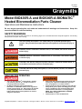
1
795-92155
07/10/08
Graymills
Model BIO436R-A and BIO536R-A BIOMATIC®
Heated Bioremediation Parts Cleaner
Operations and Maintenance Instructions
Be sure anyone operating this unit reads and understands all warnings and instructions. Keep this
manual available for reference/training.
SAFETY WARNINGS
You will find various types of safety information on the following pages and on the labels attached to Graymills equipment. The following
Safety Statements explain their meaning:
This is the safety alert symbol. It is used to alert you to potential personal injury
hazards. Obey all safety messages that follow this symbol to avoid personal injury or
death.
DANGER indicates a hazardous situation which, if not avoided, will result in death or
serious injury.
WARNING indicates a hazardous situation which, if not avoided, could result in death
or serious injury.
CAUTION, used with the safety alert symbol, indicates a hazardous situation which, if
not avoided, could result in minor or moderate injury.
CAUTION, without the safety alert symbol, is used to address practices not related to
personal injury.
READ BEFORE OPERATING
•
•
Use only Super BioteneTM cleaning fluids. Do NOT
use solvents, gasoline, etc., as they will create an
extremely hazardous situation.
Do NOT contaminate cleaning fluid with any
flammable or combustible material such as gasoline,
alcohol, mineral spirits, etc. Drain parts to be cleaned
of any flammable material or combustible material
before cleaning. Even small quantities can create a
dangerous fire hazard.
•
•
•
Never work with equipment you feel may be unsafe.
Contact your supervisor immediately if you feel a
piece of equipment is in unsafe condition.
Cleaning solutions may be irritating to skin and eyes.
Always wear gloves, apron and safety glasses when
using. If splashed in eyes, flush thoroughly with
water and follow directions on cleaning solution
MSDS. See “USE OF INDUSTRIAL CLEANING
SOLUTIONS” on page 2.
Install machine in a well ventilated area.
Graymills Corporation – 3705 N. Lincoln Ave. / Chicago, IL 60613 – Phone: 773.477.4100 Fax: 773.477.8673 – www.graymills.com – 1
795-92155
07/10/08
•
The unit has been factory set to maintain an optimum
temperature for the microbes. Do NOT attempt to
change thermostat setting.
•
This is a heated system. Always use caution when
first putting hand under liquid stream to prevent injury
from heated solution. If the liquid feels uncomfortably
hot, discontinue use, unplug machine and call
Graymills Customer Service.
•
Failure to keep proper liquid level will result in
burning out the pump and heater coil, creating a
potential fire hazard. To help prevent this, this unit is
equipped with a low liquid level device which will shut
off the pump and heater. If solution stops circulating
and the red “RESET” light becomes illuminated,
immediately turn off and unplug unit. For instructions
on filling the reservoir, please see “INSTALLATION
AND OPERATION” steps 6 through 9.
BIO436R Only
•
After extended use, the gas-spring used to assist in
opening and closing the lid may lose its ability to keep
the lid open. At the first sign of this, replace the gasspring immediately.
•
Automatic Safety Cover. Since certain soils may be
combustible, e.g., oils, greases, this unit is equipped
with a fusible safety link cover mechanism designed
to support the open cover at a slightly forward angle.
In the event of a fire, the fusible link will melt at 165ºF
permitting the cover to slam shut, limiting oxygen
supply to the fire.
•
Do not leave the unit unattended with parts in the tank
which would prevent the cover from closing
completely in the event of a fire. Keep cover closed
when unit is not in use. If the fusible link breaks, do
not operate the unit until a replacement link is
installed.
•
•
DO NOT leave the unit disconnected without power for
extended periods of time (overnight or weekends).
This will cause the microbes to go dormant. This will
adversely affect the bioremediation process. If
microbes do not reactivate after operating
temperature has been reached, a new BIO-POUCH
should be added.
If unit is to be unused, but not unplugged or turned
off, for extended periods (overnight and weekends), it
may be necessary to top-off tank to the 30-gallon mark
TM
with pre-blended Super Biotene cleaning solution to
prevent the machine from shutting down due to low
liquid levels.
POWER SUPPLY, WIRING AND
GROUNDING
•
•
•
•
•
•
Failure to permanently ground the unit and controls
before connecting to electrical power can cause
shock, burns or death.
Install ground and wiring according to local and
national electrical code requirements.
Install a fused disconnect switch on all power legs
near the unit
Disconnect and lockout electrical supply before
installing or servicing unit.
Unit must be properly grounded to prevent electric
shock hazard. Connect only to three-prong outlet.
Should cord become cracked, frayed or damaged in
any way, it should be repaired/replaced immediately
by a qualified electrician. Never use an extension
cord. (See Spare Parts List)
The full-load amperage draw for this machine is 12
amps.
USE OF INDUSTRIAL CLEANING
SOLUTIONS
•
•
•
•
•
•
•
•
•
Always wear the recommended safety apparel and
glasses.
Adequate ventilation should be provided when
operating this unit.
When making an initial batch of cleaning solution or
when adding compound, follow cleaning solution’s
directions exactly.
Industrial cleaning solutions may be irritating to some
individuals. Be certain to consult the MSDS for the
cleaning solution you are using before filling or using
parts washer.
If splashed in the eyes, follow cleaning solution MSDS
instructions.
If cleaning solution is splashed on clothing, remove
promptly and thoroughly wash any body areas which
have been in contact with solution. DO NOT permit
saturated clothing to remain in contact with skin.
Consult cleaning solution’s MSDS instructions.
Clean up fluid spills immediately. Super BioteneTM can
create a slippery surface. Also, the microbes
metabolize organic materials and could damage floor
coverings or painted surfaces.
Graymills strongly recommends that federal, state and
local authorities be consulted before proceeding with
discarding and handling of used materials. Graymills
Corporation accepts no responsibility for user’s
failure to comply with regulations.
For best results, Graymills’ recommends using only
Super BioteneTM 550 (concentrate) or Super BioteneTM
660 (pre-blended).
Graymills Corporation – 3705 N. Lincoln Ave. / Chicago, IL 60613 – Phone: 773.477.4100 Fax: 773.477.8673 – www.graymills.com – 2
795-92155
07/10/08
MACHINE INSTALLATION AND OPERATION
1.
2.
3.
4.
5.
Place unit on a smooth, level surface in a well ventilated area.
Install backsplash as show to the right (BIO536R only).
Read all warnings posted on machine.
Inspect electrical control box, cord and plug for wear or damage.
Do not use machine or add fluid if any wear or damage is noticed until impaired
components are repaired or replaced.
Install filter cartridge:
a. Unscrew filter cartridge bowl.
b. Remove clear plastic packaging from new filter cartridge and remove
BIO-POUCH from hollow center of cartridge.
c. Install new filter cartridge in the cartridge bowl.
d. Re-attach filter cartridge bowl to filter body.
Backsplash Assembly for BIO536R-A
6.
7.
8.
9.
10.
11.
12.
13.
14.
15.
16.
17.
18.
19.
Be sure electrical cord is unplugged and cleaning solution and heater coil is cool
before adding cleaning solution or performing any maintenance.
Remove center sink drain (stainless steel strainer basket, mesh strainer assembly).
Add 30-gallons of Super BioteneTM solution to the base reservoir tank.
Add one (1) BIO-POUCH of microbes to tank, found inside filter cartridge.
Put center sink drain assembly back into sink drain opening.
Plug power cord into properly grounded 115V, 15 amp circuit. Full load amp-draw of unit
is 12 amps.
Press TEST button on GFCI on rear of control (right) to ensure switch is operating
properly. Press RESET button on GFCI to prepare unit for operation.
Air pump will begin operation immediately upon power being applied to the machine and
the red “RESET” light will illuminate.
Toggle RESET switch located under the electrical box to begin operation. If the unit has
an adequate level of cleaning solution in the tank, the green “READY” light will illuminate
and the red “RESET” light will extinguish.
The amber “HEAT” light indicates power to the heater.
If cleaning solution is not at the appropriate temperature and heat is required you should
hear the thermostat engage with a “CLICK” and the amber “HEAT” light will illuminate.
Should this not happen, press the red thermostat reset button on the rear of the control
box (right). Should this problem persist: unplug machine and call factory.
When the unit reaches its predetermined temperature, the “HEAT” light will extinguish,
indicating the cleaning solution is at the proper temperature to obtain maximum cleaning
efficiency. For maximum cleaning efficiency, allow heater to warm solution for 2 to 4
hours before use.
To operate the fluid pump, toggle PUMP switch on front of electrical box to the “ON”
position.
For fluid via the flexible hose turn the directional valve counterclockwise to the left.
For fluid via the flow-thru brush turn the directional valve clockwise to the right.
Operator Interface
BIO436R-A and BIO536R-A
Front and Back
When not in use return flow-thru brush to brush clip holder to holder to avoid obstructing lid closure (BIO436R only).
20. Failure to keep proper liquid level will result in burning out the pump and heater coil, creating a potential fire hazard. To
prevent this, this unit is equipped with a low liquid level device which will shut off the pump and heater. If solution stops circulating
and the red “RESET” light becomes illuminated, immediately turn off and unplug unit. Follow steps 6 through 9 above for
instructions on refilling unit.
21.
When finished, turn pump off and close lid to minimize liquid loss due to evaporation (BIO436R only).
Do NOT unplug the machine for extended periods of time. The internal air pump and heaters are necessary for effective
bioremediation. This will cause the microbes to go dormant and will adversely affect the bioremediation process. If microbes do
not reactivate after operating temperature has been reached, a new BIO-POUCH should be added.
Graymills Corporation – 3705 N. Lincoln Ave. / Chicago, IL 60613 – Phone: 773.477.4100 Fax: 773.477.8673 – www.graymills.com – 3
795-92155
07/10/08
RECOMMENDED NORMAL MAINTENANCE
Be sure electrical cord is unplugged and cleaning solution and heater coil is cool before performing any maintenance.
1. Check fluid level in unit daily.
2. Due to evaporation and drag-out, fluid should be topped off with Super BioteneTM cleaning solution as needed.
3. A new BIO-POUCH should be added to cleaning solution in tank reservoir every 30-40 days.
4. Inspect strainer basket daily. Remove and dispose of solid waste accumulation. To assure proper drainage rinse out vapor barrier
filter daily.
5. Check operation of liquid level control. Make sure that float switch moves freely up and down.
6. Unit is equipped with a blue temperature-sensitive label on the front of the reservoir. When solution is heated, the temperature
change will cause the label to change from blue to pink. The change will occur only at or below the liquid level, allowing the level to
be determined without having to look through the drain or remove the sink.
7.
8.
9.
When control assembly is removed from reservoir, care must be taken not to damage components.
Inspect heating coil monthly, remove any deposits or build up with a soft wire brush.
Deposits and build up can cause premature failure of the heating coil.
Filter cartridge will require periodic replacement depending on the volume and types of soils involved. A significant reduction in the
flow through the flexible hose signals the need to replace the cartridge (see RECOMMENDED ANNUAL MAINTENANCE). Order
replacement cartridges, part number BIOFL1, from either your Graymills distributor or the factory.
After extended use, the gas spring used to assist in opening and closing the lid on model BIO436R may lose its ability to keep the
lid open. At the first sign of this, replace the gas spring immediately. Order part number 765-09631.
RECOMMENDED ANNUAL MAINTENANCE
Graymills recommends that the entire system be inspected and cleaned annually. To perform this maintenance:
Be sure electrical cord is unplugged and cleaning solution and heater coil is cool before performing any maintenance.
1. Remove sink drain filters and rinse.
2. Clean filter cartridge assembly:
a. Unscrew filter cartridge bowl.
b. Pour liquid from filter bowl into reservoir.
c. Remove filter cartridge and dispose of in proper manner.
d. Remove clear plastic packaging from filter cartridge and remove BIO-POUCH from hollow center of cartridge.
e. Install new filter cartridge in the cartridge bowl.
f. Re-attach filter cartridge bowl to filter body.
3. Unscrew sink hold downs.
4. Lift sink straight up until mounting ring clears reservoir and set to the side.
5. Lift off control assembly being careful not to damage heater, float switch or pump.
6.
7.
8.
9.
10.
11.
12.
13.
14.
15.
16.
When control assembly is removed from reservoir, care must be taken not to damage components.
Visually inspect pump, pump inlet filter, heater float switch, and tubing for damage or wear.
Replace all parts as necessary. Make sure all “tie-offs” for pump, heater and float switch are still in place insuring proper separation
and alignment of these components.
Clean excess accumulation off heater coil with a soft wire brush.
Inspect surface of cleaning solution and skim to remove any oil, bio-mass or debris.
Pump cleaning solution into acceptable container for future reuse.
Rinse inside of reservoir tank with clean water.
Refill reservoir tank with saved solution from step 10.
If necessary, top-off cleaning solution with enough fresh Super BioteneTM cleaning solution to bring reservoir up to 30-gallon mark.
Add a BIO-POUCH to cleaning solution
Replace control assembly and sink.
Follow steps 8 through 14 in MACHINE INSTALLATION AND OPERATION to complete annual maintenance.
Save this manual for future training. Do not allow operation without reading and understanding these instructions.
Graymills Corporation – 3705 N. Lincoln Ave. / Chicago, IL 60613 – Phone: 773.477.4100 Fax: 773.477.8673 – www.graymills.com – 4
795-92155
07/10/08
TROUBLESHOOTING
Problem
No Machine Function
Heat Not Working
Red “RESET” Light ON
Little or No Fluid Flow
Bioremediation No
Longer as Effective
Probable Cause
Suggested Remedy
Machine unplugged
Plug machine into appropriate wall socket
GFCI tripped
Press RESET button on GFCI
No power at outlet
Consult plant electrician
Thermostat tripped
Press red thermostat reset button
Heater malfunction
Contact Graymills for more information 1-888-472-9645
Heater coil dirty
Clean heater coil (see Recommended Maintenance)
Machine needs to be reset
Toggle RESET switch
Low solution level
Float sensor or control relay
malfunction
Valve shut off
Add cleaning solution
Turn valve fully to the left or right to open valve
Contact Graymills for more information 1-888-472-9645
Clogged filter
Replace filter cartridge (Part #BIOFL1)
Cracked or broken hose
Inspect and replace hose (See parts list)
Expired microbes
Add BIO-POUCH to tank solution
If your problem is not listed above or problems persist, please contact Graymills for further assistance. 1-888-472-9645
Graymills Corporation – 3705 N. Lincoln Ave. / Chicago, IL 60613 – Phone: 773.477.4100 Fax: 773.477.8673 – www.graymills.com – 5
795-92155
07/10/08
DRAWINGS AND PARTS LISTS
BIO436R-A
Electrical Control Assembly Components (Not Shown)
Items common to both the BIO436R-A and the BIO536R-A
BIO436R-A
Only
BIO536R-A
REF
DESCRIPTION
PART NO.
Complete Electrical Control Ass’y
457-40313
Toggle Switch (Pump)
770-09192
Toggle Switch (Reset)
770-92011
Toggle Switch Boot
770-08481
Indicator Light – Green
772-92079
Indicator Light – Amber
772-92078
Indicator Light – Red
772-92080
GFCI – 115V
777-09499
Float Switch
770-90167
Heater
780-90166
Pump
390-09663
Air Pump
390-92151
Tube Bulkhead Compression Fitting
735-91249
¼” Air Tubing
729-90678
8’ Power Cord and Plug
777-04152
Relay
782-92066
Relay Socket
782-92126
Rubber Condensation Guard
744-37878
Polyurethane Foam Filter
742-90883
3/8” Trim Bulb
603-37983
15
Tank
727-37995-GRAY
16
Drum
727-37883-GRAY
17
Ring
727-37995R-GRAY
18
Black Neoprene Hose
729-90327
19
Lockline Adapter
728-90796
20
Gripper Clip
769-90170
21
3-Way Fluid Valve
738-90795
22
Flex Hose and Nozzle Assembly
728-90951
23
Strainer
715-26971-81
24
Vapor Barrier
25
Filter Cup
742-34222-81
742-90144
26
Ring Mounting Thumb Screws
753-04325-81
27
Flow-Thru Brush with Hose
749-09925
28
Filter Housing
742-90186
29
Filter Cartridge
BIOFL1
30
Filter O-Ring
744-90187
31
Lid
32
Gas Spring Assembly
727-34157-GRAY
33
Fuse Link Assembly Bracket
432-34800-81
34
Linkage Bracket
435-39511-81
765-09361
35
Fuse Link Assembly
451-23482
N/A
BIO536R-A Backsplash Assembly
402-38092
Graymills Corporation – 3705 N. Lincoln Ave. / Chicago, IL 60613 – Phone: 773.477.4100 Fax: 773.477.8673 – www.graymills.com – 6
795-92155
07/10/08
ELECTRICAL SCHEMATIC
WARRANTY INFORMATION
G r a y m i l l s Corpora t i o n warrants that the equipment manufactured and delivered, when properly installed and maintained, shall be
free from defects in workmanship and will function as quoted in the published specification. G r a y m i l l s does not warrant process
performance, nor assume any liability for equipment selection, adaptation, or installation.
Warranty does not apply to damages or defects caused by shipping, operator carelessness, misuse, improper application or installation,
abnormal use, use of add-on-parts or equipment which damages or impairs the proper function of the unit, and modifications made to
the unit. Warranty does not apply to expendable parts needing replacement periodically due to normal wear and tear.
A new Warranty period shall not be established for repaired or replaced materials or products. Such items shall remain under Warranty
for only the remainder of the Warranty period of the original material or product.
THE FOREGOING WARRANTIES ARE IN LIEU OF ALL OTHER WARRANTIES, WHETHER ORAL, WRITTEN, EXPRESSED,
IMPLIED OR STATUTORY. G R AY M I L L S CORPORATION MAKES NO OTHER WARRANTY OF ANY KIND, EXPRESS OR
IMPLIED. ALL IMPLIED WARRANTIES OF MERCHANTABILITY AND FITNESS FOR A PARTICULAR PURPOSE WHICH EXCEED
THE AFORESTATED OBLIGATION ARE HEREBY DISCLAIMED BY GRAYMILLS CORPORATION AND EXCLUDED FROM THIS
SALE. G r a y m i l l s warranty obligations and Buyer remedies (except to title), are solely and exclusively stated herein. In no case will
G r a y m i l l s be liable for consequential damages, loss of production, or any other loss incurred due to interruption of service.
G r a y m i l l s ' obligation under this Warranty shall be limited to:
1. Repairing or replacing (at G r a y m i l l s sole discretion) any non-conforming or defective component within one year from
the date of shipment from G r a y m i l l s .
2. Repairing or replacing (at G r a y m i l l s sole discretion), components supplied by, but not manufactured by G r a y m i l l s , to
the extent of the warranty given by the original manufacturer.
Buyer must give G r a y m i l l s prompt notice of any defect or failure.
If you believe you have a Warranty claim, contact G r a y m i l l s at (773) 248-6825. Any return material must have an RMA number on
the outside of the package and shipping prepaid or shipment will be refused. G r a y m i l l s will promptly examine the material and
determine if it is defective and within the Warranty period.
Graymills Corporation – 3705 N. Lincoln Ave. / Chicago, IL 60613 – Phone: 773.477.4100 Fax: 773.477.8673 – www.graymills.com – 7