1
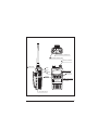
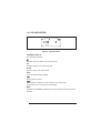
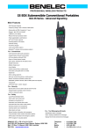
HT981 / 917
v04/08
UHF submersible transceiver
OWNERS MANUAL
H
CH
MENU
2
M
II 2 G Ex ib IIC T4
EPSILON 08ATEX2374X
Use only with Entel approved
accessories - see user guide
DO NOT CHARGE IN A
HAZARDOUS AREA
ATEX approved
Intrinsically Safe
II 2 G
Ex ib IIC T4
SUBMERSIBLE
Submersible
Dependable
Tough
CE COMPLIANCE STATEMENT
All HT981 / HT917 transceivers display "CE" on the serial number label,
indicating compliance with all relevant EC directives.
DECLARATION OF CONFORMITY
We Entel UK Limited,
OF:
4 Elstree Gate, Elstree Way
Borehamwood, Herts
WD6 1JD
United Kingdom
Declare under our sole responsibility that the product:HT981 UHF / HT917 Lowband VHF handheld transceiver
Serial Number
To which this declaration relates, is in accordance with directive 95/5/EC and
conforms to the following standard or other nominative documents:EN 300 086-2 V1.1.1, EN 301 489-1 V1.5.1:2003, EN 60065:2002
Following provisions of the R&TTE directive.
And
Directive 94/9/EC (ATEX)
Harmonised Standards:
BS EN 60079-0:2006
BS EN 60079-11:2007
M. Austin
Quality Manager
Quality Manager
March 2008
2
Notified Body 1712
Epsilon Compliance Services
Deeside Lane, Chester CH1 6DD
Certificate number EPSILON 08ATEX2374X
1.1 PREPERATION PRIOR TO USE
1. ATTACHING THE BELT CLIP
Align the belt clip with the plastic slots of the battery pack. Slide the
belt clip downwards onto the battery pack, pushing firmly until a click
is heard.
2. BATTERY REMOVAL/ATTACHMENT
1. Turn the transceiver off.
2. Hold the radio and rotate the battery release screw anti-clockwise.
Ensure that you do not hold the battery pack when unscrewing
the release screw as the radio will fall to the floor!
3. To attach the battery: firstly,
place the battery against the
bottom of the radio, then
hinge the battery into place
To remove rotate
the screw
anti-clockwise
against the transceiver. Rotate
the battery locking screw
clockwise until finger tight Do
not over tighten the screw.
Figure 1.
Battery removal / Attachment
1.2
ATTACHING AUDIO ACCESSORIES
Remove the accessory connector cover located on top of the radio by
rotating its screw anti-clockwise.
Locate the audio accessory plug on top of the socket and rotate the locking
screw clockwise until finger tight (do not use a screwdriver or coin etc).
Note: The accessory socket is only waterproof with either the accessory
socket cover in place or with an accessory connected.
(Refer to certificate EPSILON 08 ATEX 2374X for permitted accessories)
3
Models suffixed S have alternative frequency ranges but are identical in
operation to the models without the suffix.
1.3 CONTROLS AND INDICATORS
1.
ON/OFF BUTTON
Momentarily press to switch on. Press and hold to switch off.
2.
VOLUME CONTROL
Rotate clockwise to increase received volume. Rotate
3.
anticlockwise to reduce received volume.
PUSH TO TALK SWITCH
4.
Hold down to transmit, release to receive.
UP/DOWN buttons
Select the desired channel by pressing the UP/DOWN buttons.
5.
For fast channel selection hold down for more than 1 second.
LAMP/LOCK button
Momentarily press to turn backlight on/off. Press and hold to turn
backlight on / off. Press and hold to turn monitor on / off.
6.
P1 & P2 buttons
Dealer programmable.
7.
8.
button
Enter/Select.
M button
Menu select button.
9.
MON buttons
Dealer programmable.
10. ANTENNA
Connects the supplied flexible antenna or an optional external
aerial adaptor
11. BATTERY
Rechargeable Lithium-lon battery packs.
12. ACCESSORY SOCKET
To connect to an Entel approved audio accessory
4
12 ACCESSORY CONNECTOR
ANTENNA CONNECTOR
VOLUME CONTROL
LAMP/LOCK
MON
ENTER/SELECT
PTT
MENU
UP/DOWN
M
POWER
SWITCH
II 2 G Ex ib IIC T4
EPSILON 08ATEX2374X
Use only with Entel approved
accessories - see user guide
DO NOT CHARGE IN A
HAZARDOUS AREA
SUBMERSIBLE
P1 & P2 DEALER
PROGRAMMABLE
BUTTONS
11 BATTERY PACK
Figure 2. CONTROLS & INDICATORS
5
1.4 LCD INDICATORS
H
CH
MENU
2
Figure 3. LCD indications
CHANNEL DISPLAY
The operating channel.
Appears when key bleep sound is turned on.
H/L
Indicates High or Low power selected.
SCAN
Appears when scan is activated.
VOX
Voice operated mode enabled.
The keypad is locked.
The Lithium-lon battery of your transceiver is continually
monitored for your convenience and safety.
MON
Indicates CTCSS/DSS disabled on receive allowing monitoring of the
channel.
6
1.5 RECEPTION
1. Turn the transceiver on by momentarily pressing the power button.
A power on tone is generated after 1 second to indicate the
transceiver has passed its self-diagnostic test. Select the desired audio
level by rotating the volume control clockwise.
2. Select the desired channel using the [UP/DOWN] buttons.
3. When receiving a signal the LED indicator illuminates green.
1.6 TRANSMISSION
1. Perform steps 1 through 3 of RECEPTION.
2. Before transmitting, monitor the channel and make sure it is clear.
3. When receiving a signal, wait until the signal stops before transmitting.
The transceiver cannot transmit and receive simultaneously.
4. Press the [PTT] (push-to-talk) switch to begin your transmission.
To confirm transmission in progress the LED illuminates RED.
5. Holding the transceiver 2 inches from your mouth speak slowly and
clearly into the microphone.
6. When the transmission is finished, release the [PTT] switch.
7
1.7 BATTERY SAFETY
The battery pack of your transceiver contains lithium-Ion cells.
This type of battery stores a charge powerful enough to be dangerous
if misused or abused, especially when removed from the transceiver.
Please observe the following precautions:
DO NOT SHORT BATTERY PACK TERMINALS
Shorting the terminals that power the transceiver can cause sparks,
severe over heating, burns, and battery cell damage.
If the short is of sufficient duration, it is possible to melt the battery
components. Do not place a loose battery pack on or near a metal
surface or objects such as paper clips, keys, tools etc.
When the battery pack is installed on the transceiver, the terminals
that transfer current to the transceiver are not exposed.
The terminals that are exposed on the battery pack when it is mounted
on the transceiver are charging terminals only and do not constitute a
hazard.
DO NOT INCINERATE
Do not dispose of your battery in a fire or incinerator.
The heat of fire may cause battery cells to explode and/or release
dangerous gases.
DISPOSE OF BATTERY PACKS PROPERLY
Lithium-Ion battery packs must be recycled or disposed of properly.
For requirements in your area, check with the dealer from whom you
purchased your transceiver.
8
1.8 NOTES
Use this page to record important information, such as the serial
number of your HT900 V2R1 Series transceiver, and any of the
frequencies and sub-tones programmed by your dealer.
9
10
Certification
ATEX approved
Intrinsically Safe
EPSILON 08ATEX2374X
II 2 G
Ex ib IIC T4
The HT981/HT917 must always be used within the terms of its certification.
Keep the HT981/HT917 away from aggressive substances. If used in a
hostile environment, extra protection may be needed.
To prevent ignition of hazardous atmospheres, batteries must only
be charged in an area known to be non hazardous.
No unauthorised repairs are permitted.
This equipment is designed and manufactured to protect against
other hazards as defined in paragraph 1.2.7 of Annex II of the ATEX
Directive 94/9/EC
HT900 series radios must not be used outside of the ambient temperature
range Tamb = -20ºC to +40ºC
The battery pack must be recharged only with one of the ENTEL battery chargers listed below:
CSAHT 1-way intelligent rapid charger, 110-230v
CSBHT 6-way intelligent, rapid charger, 110-230v
CCA230 1-way trickle charger with 230V mains adapter
CCA110 1-way trickle charger with 110V mains adapter
CCA12 1-way trickle charger with cigar lighter lead, 12V DC operation
Refer to certificate EPSILON 08 ATEX 2374X for permitted accessories
11
Registered Community Design Application 000044375
U.S. Design Patent Pending No. 29/183,829
Copyright and Unregistered Design Right Entel UK 2008.
All rights reserved
Copyright Entel UK Ltd, London