1
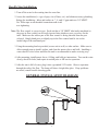
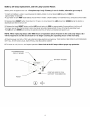
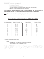
DWS/SE/DWSW
Series
U.V. Disinfection
INSTALLATION & OPERATION MANUAL
This manual covers installation, operation and maintenance
requirements for DWS/SE/DWSW U.V. Disinfection Units.
Models DWS-7, 15, and SE-7, 15, and DWSW-8, 15.
It is important that those responsible for the installation of this
equipment, as well as the owner / operator, read this manual
and carefully follow the instructions and guidelines.
AQUA TREATMENT SERVICE, INC.
194 HEMPT ROAD
MECHANICSBURG, PA 17050
ph: (717) 697-4998
fax: (717) 697-5035
Revised: 8/08
SAFETY INSTRUCTIONS
WARNING - to guard against injury, basic safety precautions should be observed,
including the following:
1.
2.
3.
4.
5.
6.
7.
8.
9.
10.
READ AND FOLLOW ALL SAFETY INSTRUCTIONS.
DANGER -To avoid possible electric shock, special care should be taken since
water is present near electrical equipment. Unless a situation is encountered
that is explicitly addressed by the provided maintenance and troubleshooting
sections, do not attempt repairs yourself, refer to an authorized service facility.
Carefully examine the disinfection system after installation. It should not be
plugged in if there is water on parts not intended to be wet.
Do not operate the disinfection system if it has a damaged power cord or plug,
if it is malfunctioning or if it is dropped or damaged in any manner.
Always disconnect water flow and unplug the disinfection system before
performing cleaning or maintenance activities. Never yank the power cord to
remove it from an outlet, grasp the plug and pull to disconnect.
Do not use this disinfection system for other than the intended use (potable
water applications). The use of attachments not approved, recommended or
sold by the manufacturer / distributor may cause an unsafe condition.
Intended for indoor use. Do not install this disinfection system where it will be
exposed to the weather. Do not store this disinfection system where it will be
exposed to temperatures below freezing unless all the water has been drained
from it and the water supply has been disconnected.
Read and observe all the important notices and warnings on the water
disinfection system.
If an extension cord is necessary, a cord with a proper rating should be used. A
cord rated for less Amperes or Watts than the disinfection system rating may
over heat. Care should be taken to arrange the cord so that it will not be
tripped over or accidentally pulled from the outlet.
SAVE THESE INSTRUCTIONS.
WARNING: The light given off by this unit can cause serious burns to unprotected eyes
and skin. Never look directly at a lit UV lamp. When performing any work on the UV
Disinfection System, always unplug the unit first. Never operate the UV system while the
lamp is outside of the UV chamber.
WARNING: The UV lamp inside of the disinfection system is rated at an effective life
of approximately 9,000 hours. To ensure continuous water treatment, replace the UV lamp
annually with the appropriate Aqua Treatment Services UV lamp. Failure to comply may
present a fire hazard.
FUNCTION:
The function of this ultraviolet disinfection unit is to provide in excess of 99% reduction of all water
borne pathogenic (disease causing) bacteria.
Model DWS/SE/DWSW series have a number code designation correspondent to the maximum gpm
(gallons per minute) flow rate of the unit. I.E.- DWS-7 has a maximum flow capacity of 7 gpm.
Applications:
Ultraviolet Germicidal Disinfection
A.T.S. Ultraviolet Disinfection Units are designed to destroy micro-organisms in water supplies. The
Ultraviolet lamp peak radiation of 254 nanometer wavelength (nm) destroys or inactivates the D.N.A.
(deoxyribonucleic acid) which absorbs the Ultraviolet radiation. A.T.S. Germicidal Disinfection units
meet minimum dosages of 30,000 microwatt second per square centimeter.
MAXIMUM CONCENTRATION LEVELS BEFORE ULTRAVIOLET:
Turbidity.................................5NTU
Color.......................................None
Manganese........................0.05 ppm
Hardness..........................................7 gpg
Iron...................................................0.3 ppm
pH....................................................6.5 - 9.5ppm
Important Note - Pre-filtration equipment may be required if these parameters cannot be maintained.
Flow rate must not exceed rated capacity of the unit.
DESCRIPTION OF EQUIPMENT:
The DWS/SE/DWSW series are of unique design with an ultraviolet germicidal lamp housed within a
single quartz sleeve surrounded by a stainless steel pressure chamber. The chamber is fabricated out of
304 Stainless Steel. A removable stainless steel cover exposes electrical components for servicing,
when required.
The DWS/SE series come with an ultraviolet lamp designed with one pin at each end. This type of lamp
has a socket connected to each pin. The DWSW-8 model comes with a bi-pin connection at each end.
A stainless steel threaded nipple with a brass compression nut and O-Ring is located at each end of the
disinfection chamber.
The quartz sleeve is intended to be placed through the disinfection chamber and will slightly protrude
from each threaded nipple end. The ultraviolet lamp is placed within this quartz sleeve. The U.V. light
shines through this specially designed hard quartz sleeve for maximum disinfection efficiency to meet
the requirements for bacteria reduction in potable water.
The inlet/outlet are located on one side of the chamber and may be interchanged as to designation
dependent upon installation. A Site Port is provided for safe and easy view of operation.
1
GENERAL CONSIDERATIONS FOR ALL DISINFECTION UNITS:
1.
When installing the equipment, it is necessary that the unit be isolated from vibration,
heavy equipment, and poorly connected piping.
2.
Incoming water temperature to the unit should not exceed 35° minimum to110° maximum
degrees Fahrenheit.
3.
The operating pressure should not exceed 100 psi.
4.
Before putting the unit into final operation follow sanitation procedures as outlined in this
manual for proper disinfection. Sanitizing all discharge piping and fittings with household
bleach from disinfection unit to point of use removes existing contaminants and gives
the unit a “clean start.” Be sure to rinse with U.V. treated water.
5.
A proper flow control must be used to insure only the designated flow through the unit.
GENERAL PRECAUTIONS TO BE FOLLOWED AT ALL TIMES:
1.
Always disconnect electrical power to any U.V. unit before servicing.
2.
Under no circumstances should personnel look at a U.V. lamp in operation
(EXCEPT through an external Site Port lens located on the outside of the unit).
3.
U.V. disinfection units must always be properly grounded.
INSTALLATION:
The DWS/SE/DWSW series are always placed after the pressure tank and any other type of treatment
devices (i.e. softeners, filters).
These units are normally installed in a vertical position in an enclosed area with good ventilation. Allow
clearance of at least the unit’s length at one end for quartz sleeve and bulb replacement. Four (4) anchor
bolt holes are provided for proper wall support. Use wall plugs with screws for sufficient support
(not included).
If your piping system is subject to impulse pressure resulting in a “water hammer” condition, a surge
tank or other means must be provided to remove this condition; otherwise, this extreme shock pressure
condition may rupture or fracture the quartz sleeve.
Make all plumbing connections to allow for ease of service. Be sure to follow all local plumbing codes
and U.V. restriction requirements where specified by local authorities.
On models requiring a U.V. monitor or light detector, the U.V. should be mounted in a vertical position.
2
Step By Step Installation:
1. Turn off the water before cutting into the water line.
2. Assess the installation (i.e. type of pipe, size of lines, etc.) and obtain necessary plumbing
fittings for installation. Inlets and outlets on 7, 8, and 15 gpm units are 3/4" MNPT.
Use Teflon tape on all threaded connections and avoid
over tightening.
Note: The flow control is a press in type. Each unit has a 3/4" MNPT inlet/outlet machined so
the press in flow control can be easily inserted into whichever port you select for the
inlet. Make sure the rubber part of the flow control is facing outward from the port
selected. Simply hand press or slightly tap in the flow control until it sits on the
inside ledge of the machined port.
3. Using the mounting bracket provided, secure unit to wall, or other surface. Make sure to
allow enough room to install, replace, and clean the quartz sleeve and bulb. Installing a
water shut-off valve before and after the unit is recommended to make servicing easy.
4. After mounting, install quartz sleeve, O-Ring, and bulb per instructions. Turn on the water
slowly, check for leaks, and repair as needed prior to full service operation.
5. After the unit is full of water, plug it into a grounded 110V outlet. Observe operation
through the safety Site Port. The lamp will show a bright blue glow. If any problems
are noted, consult trouble shooting guide.
GENERAL INSTALLATION DIAGRAM
3
4
5
REQUIREMENTS FOR CLEANING THE QUARTZ SLEEVE:
As water passes through the U.V., minerals, debris and other matter in the water may deposit onto the
quartz sleeve. After sufficient film has formed on the quartz sleeve, the ability of the ultraviolet
germicidal rays to pass though the quartz sleeve and into the water may be impaired. Therefore, it is
necessary to determine a cleaning schedule for the quartz sleeve. The frequency will depend on the
specific type of water conditions. If the water has been processed through deionization, reverse
osmosis, or is distilled, cleaning may be required only once per year. If untreated water is used, the
cleaning frequency will vary. A minimum of once yearly is standard recommendation for cleaning and
lamp replacement. Contact your local dealer for scheduling this service. Your specific situation will
vary the frequency time according to the water quality of the home or facility application.
QUARTZ SLEEVE CLEANING PROCEDURES:
To clean the quartz sleeve, turn off the water flow to the disinfection unit, turn power off, and disconnect the electrical service to the lamp pins. Carefully remove the U.V. lamp. Loosen the compression
nuts with O-Rings and remove the quartz sleeve while draining the water from the chamber. The quartz
sleeve may then be washed with a mild soap and hot water solution and rinsed clean with hot water.
Should this be insufficient to clean the quartz sleeve, a mild acid may be used (i.e. vinegar). Be certain
to follow all recommended safety and handling procedures on the acid container. It is important to
handle the quartz sleeve with care to prevent breakage. Make certain that all finger prints are wiped
clean before reinstalling (see installation of the quartz sleeve). Replace O-Rings [ATS8-544(2)] every
time a quartz sleeve is cleaned or replaced.
NOTE: On DWSW series units equipped with a wiper rod(s), it will be necessary to clean the quartz
sleeve on a regular basis. This avoids any possible buildup of debris or staining. Preferably proper
pre-filtration equipment may be necessary to eliminate exposure to contaminants that cause this.
6
U.V. LAMPS:
INSTALLATION OF THE ULTRAVIOLET LAMPS:
**DO NOT PUT POWER ON AT THIS TIME!**
CAUTION: Never look directly at a operating U.V. lamp operate a U.V. lamp outside the
disinfection chamber.
Make sure unit is unplugged when installing or servicing ultraviolet lamp. Remove any paper tabs on
the U.V. lamp and avoid allowing fingerprints and other debris to deposit. Carefully place the bulb
inside the quartz sleeve leaving enough space to connect the socket connector to the lamp pins. Insert
the protective polyurethane endcaps into the quartz open ends to secure the lamp(s) in place or reinstall
brass dust covers.
ULTRAVIOLET LAMP MAINTENANCE REQUIREMENTS:
The U.V. lamp is rated for 9,000 hours of continuous use. After this period of time, the U.V. lamp has
undergone a photochemical change. While the lamp will not normally be burned out, the lamp quartz
may no longer emit the 254-nm shortwave U.V. to effectively kill bacteria. Failure to replace the U.V.
lamps every 9,000 hours may cause bacteriological breakthrough. Should the use of the
disinfection unit be intermittent, in no case should the U.V. lamp be used for more than 24 months
regardless of the number of hours of operation due to normal shelf life degradation of the U.V. bulb.
Changing the quartz sleeve should be done at the same time U.V. lamp replacement is scheduled.
It is recommended that your water supply be tested periodically (yearly) through your local health
department or approved certified laboratory.
ELECTRICAL:
The DWS/SE/DWSW series are furnished with 6' line cord that will plug into a 110V outlet. Electrical
receptacles must be properly grounded for safe operation. Improper grounding will void any warranty.
When possible use a separate breaker to minimize voltage fluctuations and avoid accidental shut off.
After unit is installed and water is turned on, plug the unit into 110V wall receptacle. View lamp
operation through safety Site Port lens. NOTE: Avoid exposing your eyes to U.V. light.
7
SANITATION PROCEDURE FOR INSTALLATION
AND BULB REPLACEMENT:
HOW TO DISINFECT A WATER SYSTEM:
Every new well, or existing water supply system that has been disrupted for service or repair, should be
disinfected before it is returned to use. Water in the well and storage tank should be treated with a strong
chlorine solution to destroy disease organisms. All pipelines and fixtures in the distribution system should be
rinsed and flushed with chlorinated water. Upon installation of a U.V. disinfection unit or yearly bulb replacement service, disinfection with chlorine to initially flush the system is recommended to assure line sanitation
prior to U.V. start up.
The source of chlorine can be ordinary household liquid laundry bleach (about 5.25% available chlorine). The
quantity required depends on the volume of water to be treated. The United States Environment Protection
Agency (EPA) indicated that about 100 parts of chlorine, by weight, mixed in a million parts of water will
destroy essentially all water-borne disease organisms. Table 1 shows the quantity of liquid bleach required to
disinfect wells of various diameters and depths.
DISINFECTION PROCEDURE:
DRILLED WELLS: Remove the cap or seal form the casing and measure the depth of the water in the well,
then refer to Table 1 to determine how much chlorine solution should be used. In some instances removing the
seal to measure the water can be a difficult task, and it is easier to guess at the quantity of disinfectant needed
than it is to make a more accurate determination (footnote, Table 1). As a general rule, it is better to use too
much chlorine than too little. The disadvantage in doing so is that it will take longer for the taste and odor to
leave the system.
Mix the required chlorine disinfectant with a few gallons of water in a plastic bucket and pour it into the well.
If the seal has a removable vent, unscrew the pipe or plug and pour the disinfecting solution through the hole
into the well. For maximum effectiveness, the chlorine must be mixed with the water in the well. This can be
accomplished by connection a hose to a faucet beyond the pressure tank, and circulating the water from the tank
back into the casing. After about 20 minutes, close this faucet, open another at the far end of the distribution line
and let the water run until the odor of chlorine can be detected.
Close this faucet and repeat the procedure for each of the other outlets on the line until chlorinated water can be
detected throughout the entire system. Keep this water in the pipeline for at least 6 hours, (preferably overnight)
then start the pump and flush the system. Continue pumping until the odor of chlorine disappears. For U.V.
installations or replacement bulb servicing, this can be shortened to 20 minute time.
8
LARGE DIAMETER WELLS: Dug or bored wells should be disinfected in the same way as a drilled
one. Lower the water level as much as possible, remove the sand, silt and debris, and then treat with the chlorine solution. Mix thoroughly by circulating the water back into the well and use the hose to rinse the interior
lining of the well. Do not try to disinfect an unprotected, unlined well because new seepage or surface
contamination will flow into the water about as fast as you can disinfect it. Disinfect the pipeline distribution
system as indicated for drilled wells.
SPRINGS AND CISTERNS: Mix about ½ cup of household bleach in 5 gallons of water and use this to
scrub the walls of the spring box or holding tank. With a constant flow of fresh water from the spring, there is
probably no way of detaining the chlorine solution in the reservoir for more than a few minutes. However, the
chlorinated water should flow through the pipeline to disinfect the distribution system. Cisterns can be disinfected in the same way but a source of clean water will be needed to flush the dirty waste out of the system.
For additional information about how to protect wells and springs and keep them from becoming contaminated,
call or visit your local Cooperative Extension office, or your nearest certified water treatment specialist.
TABLE 1 ** Quantity of solution mixed - 5.25% available chlorine (laundry bleach) for disinfecting
wells, or 52,500 P.P.M..
WQA recommends 50mg/l or ppm chlorine concentration.
Formula -
C2 X V2 / C1 = V1
C1= Household Bleach (52,500 P.P.M.)
V1= Chlorine Amount Needed
C2= 50 mg/L
V2= 80 gallons holding time
I.E. 50-ml/g X 80 gal= 4000/52,500= .08 gallons of chlorine (5.25%)
.08 gal chlorine (5.35%) X 128 (oz/gal) = 10.24 oz (5.25%)
Dug Wells - 3 to 4 feet diameter - 4 cups per foot of water
Drilled Wells - 3 to 8 inch diameter - 1 cup per foot of water
TOO MUCH CHLORINE IS BETTER THAN TOO LITTLE:
**
In situations where it is inconvenient to determine depth of water or diameter of a drilled well, a
minimum of 1/2 gallon of household bleach may be used for wells up to 8 inches in diameter with estimated to
be less than 80 feet deep; 1 gallon should be used for similar size wells with water deeper than 80 feet. In case
of a well yielding more than 50 gallons per minute, special procedures are required. Seek the advice of a
certified water treatment specialist.
Wait a day or two before you have another sample tested. Do not take a sample for testing if the odor of
chlorine is still present in water.
9
REMEMBER - To make your water supply safe:
- Locate your well properly.
- Protect it from surface contamination.
- Test water periodically for coliform bacteria. (Home-yearly, Farm-2X yearly)
- Chlorinate, or filter and disinfect the water if necessary.
When installing an ultraviolet disinfection system, a prefilter with sump may serve as a source to
sanitize the water lines only. For whole system disinfection follow procedure as outlined above.
Source: The Pennsylvania State University College of Agriculture Cooperative Extension.
How to Sanitize a Water System Using Well Sanitizer Pellets
Table 1
Well Diameter Inches
2
3
4
5
6
8
10
12
24
36
Weight of Pellets lbs. - oz.
Cups of Pellets
0 - 1.5
0 - 3.0
0 - 6.0
0 - 8.0
0 - 12.0
1 - 5.0
2-0
3-0
12 - 0
26 - 0
1/4
2/5
3/4
1
1-1/2
2-1/2
4
6
24
---
Number of Pellets
40
80
140
200
300
500
800
----------
* To produce a 400 P.P.M. chlorine dosage
NOTE:
Pellets Weight = 1.14 gram each, 25 pellets/oz., 400 pellets/lb.
1 cup of pellets = 1/2 lb., or 200 pellets, or 8 oz.
To produce a 400 P.P.M. chlorine concentration, to sanitize a water system, use one-half (1/2) pound chlorination pellets for each 100 gallons of water in the system (1/2 lb/100 gal= 8 oz/100 gal= 200 pellets/ 100 gal= 1
cup pellets/100 gal). Table 1 shows how many pellets too use per 100 feet of water in various diameter wells.
10
DRILLED WELLS:
1. Remove the cap or seal from the casing and measure the depth of the water in the well, then refer to
Table 1 to determine how many chlorine pellets should be used. In some instances removing the seal
to measure the water can be a difficult task, and it is easier to estimate well and water depth from well
log or other records.
2. Remove well cap and determine if there is an unobstructed path from the top of the well to the
water level. If it is not possible to remove the well cap, remove vent or sanitation access plug.
3. Drop one pellet into the well and listen to hear if it hits the water. If the pellet hits the water, drop
one-half the number of pellets determined to be needed into the well. These will sink to the bottom
and sanitize the lower part of the well.
4. Mix the remaining pellets in a few gallons of water in a CLEAN plastic container and pour the
solution into the well.
5. In order to mix the chlorine thoroughly throughout the entire water system, it is necessary to
recirculate the water in the well. This can be accomplished by connection a hose to an out side faucet
that is located after the pressure tank. Use hose to run water back down the well (this also rinses upper
portion of well). After about 15 minutes of recirculation the water, a strong chlorine odor should be
apparent. Turn off hose.
6. Bypass water softener and filters and open each water outlet in the water system until chlorine is
present in water. This procedure assures that all the water in the system is chlorinated.
7. Allow the chlorinated water to stand in the system for at least one (1) hour, and preferable overnight.
After this, open an outside faucet system until water runs chlorine free. Repeat flush operation on each
faucet in system.
NOTE:
A.Chlorine may break loose iron deposits, slime and organic material. This material will make
the water run colored. The material broken loose may plug pump screens. Do not continue to
run pump if water doesn’t flow.
B. The high level of chlorine required to sanitize a water system is corrosive to most metals and
chlorine solution must not be allowed to remain in water system more than 36 hours before
being completely flushed from system.
8. After system has been completely flushed, perform a bacteriological analysis on the water
following all applicable procedures.
NOTE:
Always follow the sanitizing procedure required by applicable state or local laws.
EPA Registered: Well sanitizer pellets are EPA Registered for sanitizing potable water. EPA Registration
No. 50510-1
11
TROUBLESHOOTING GUIDE
PROBLEM
CAUSE
CORRECTION
U.V. lamp will not light
Check input voltage if below
or above 120 volts
Install a voltage regulator
or outlet defective
Line cord disconnected
Check, replace
Defective U.V. lamp
Replace
Defective lamp ballast
Check output voltage
Replace ballast
Loose open-circuit wire
Trace out and repair
Defective or cracked O-Ring
Replace O-Ring
O-Ring not seated properly
Replace O-Ring
Leak at quartz nipple
OPTIONAL FEATURES:
U.V. SENSOR WITH AUDIBLE ALARM:
Units with this option require a separate power source. This unit can be added at anytime. It features
a built-in audible alarm and fail-safe circuitry designed to activate a solenoid valve when dosage falls
below a preset level. This is a proprietary true U.V. monitor and control system.
12
LIMITED WARRANTY
All parts of the disinfection unit, with the exception of the U.V. lamp, are guaranteed for
one (1) year against defective parts and workmanship. The stainless steel disinfection
chamber on the DWS, SE, and DWSW series is guaranteed for ten (10) years. Any
component which fails to operate satisfactorily within their time period will be replaced
free of charge under the following conditions:
NOTIFY YOUR LOCAL DEALER OR DISTRIBUTOR OF ANY PARTS
SUSPECTED OF BEING DEFECTIVE.
Upon approval by Aqua Treatment Service Inc., the Dealer/Distributor should return the
item to Aqua Treatment Services, Inc. 194 Hempt Road, Mechanicsburg, PA 17050
(prepaid). If a part proves to be defective, it will be repaired or replaced and returned to
the Dealer/Distributor freight paid.
It is the dealer/customer responsibility to reinstall any components which require
replacement under warranty. No labor will be covered under this Limited Warranty.
Aqua Treatment Services' or sellers liability is limited to the repair or replacement of any
component found to be defective, and in no case shall we be held liable for damage, either
immediate or subsequent, arising out of the use of this equipment.
13
SPECIFICATIONS
MODEL #
DWS-7/SE-7
DWS-15/SE-15
DWS-24/SE-24
DWSW-8
DWSW-15
DWSW-24
Maximum
Capacity G.P.M.
7
15
24
8
15
24
Shipping Weight
19
28
45
22
28
47
No. of Lamps
1
1
2
1
1
2
KW @ 120V
.038
0.07
.067
0.07
0.16
.038
0.037
.067
0.07
0.16
KW @ 220V
.033
0.07
.064
0.07
0.14
.033
0.037
.064
0.07
0.14
AMPS @ 120V
.32
0.6
.56
0.6
1.3
.32
0.65
.56
0.6
1.3
AMPS @ 220V
.15
0.3
.29
0.3
0.6
.15
0.3
.29
0.3
0.6
Inlet/Outlet Size
¾'' Std.
MNPT
¾'' Std.
MNPT
1½" Std.
FNPT
¾'' Std.
MNPT
¾'' Std.
MNPT
1½" Std.
FNPT
Overall Dimension
Inc. Wall Mount
LxWxD
18" x 4" x 7"
36" x 4" x 7"
36" x 10 x 7"
24" x 9" x 6½"
36" x 4" x 8"
36" x 10" x 8"
Disinfection
Chamber (wetted
parts) Material
304 SS Tubing
304 SS Tubing
304 SS Tubing
304 SS Tubing
304 SS Tubing
304 SS Tubing
Cabinet Housing
Material
304 SS #4 Polish 304 SS #4 Polish 304 SS #4 Polish 304 SS #4 Polish 304 SS #4 Polish 304 SS #4 Polish
ATS-254M
ATS-254E Monitor
N/A
Optional
Optional
Optional
Optional
Optional
U.V. Dosage
> 30,000
μw sec./cm²
> 30,000
μw sec./cm²
> 30,000
μw sec./cm²
> 30,000
μw sec./cm²
> 30,000
μw sec./cm²
> 30,000
μw sec./cm²
14
SUGGESTED PROCEDURE FOR OBTAINING STERILE WATER SAMPLES:
Prior to taking the water sample, be sure to have on hand an adequate supply of sterile bottles. These
sterile bottles should be obtained from a reputable laboratory and should have been autoclaved and
contained within a plastic outer wrapping.
1.
Prior to taking the sample, it is imperative that the sample cock, faucets, etc. be opened
at full force for a complete three and one half minutes.
2.
After the valve has been left wide open for three and one half minutes, reduce the flow
to a reasonable stream of water. Flow to drain an additional three minutes.
3.
Open the sterile bottle or sterile container being used. Holding the cap in a down
position, the operator should then hold his breath while taking the sample so as to
avoid oral contamination of the sample. The operator must not allow his finger to
touch the inside of the cap or the neck of the bottle.
4.
After the sample has been taken, the cap should immediately be tightly placed on the
sample container.
5.
The sample container should be placed in a plastic wrapping and should be taken to
the laboratory for plating as soon as possible following the above procedure.
We recommend duplicate samples be taken at each test station during each specific test so as to avoid
loss of sample through laboratory error and to insure reasonable validity through comparison.
Check with your local laboratory to assure proper sampling and submittal procedure.
15
WIRING DIAGRAMS
16
17
18
19
20
DRAWINGS AND PART NUMBERS
21
DWS-7 Explosion
22
DWS-7 Parts List
CODE
PART#
1
2
3
4
5
6
7
8
9
10
11
12
13
14
15
16
17
18
19
ATS-5100
ATS-5173
ATS-5172
ATS-5171
ATS8-544
ATS5-411
ATS8-546
ATS-4010
ATS-N1156
ATS-7030
ATS-R01
ATS-F07
ATS-4000
ATS-6L1
ATS1-420
ATS6-211
ATS1-805
ATS-6100
ATS-7600
DESCRIPTION
Chamber
Site Port O-Ring
Site Port Lens
Site Port Nut
End Nut O-Ring (seal quartz sleeve)
Brass End Nut
O-Ring (for shroud on end nut)
Socket w/ Wire
Brass Shroud
Grommet (for wire assy. in shroud)
3/4” Flo.-Et. Retainer 7 gpm
7 gpm Flo.-Et.
Power Cord
Strain Relief (for Power Cord)
Ballast 120V/60Hz
Quartz Sleeve
Bulb
Cover w/ Hole for Plastic Lens
Plastic Sight Lens (for cover)
KITS
ATS-4025
ATS-5177
Kit:
5 thru 10
Lens Kit: 2 thru 4
23
QTY.
1
1
1
1
2
2
2
2
2
2
1
1
1
1
1
1
1
1
1
DWS-15 Explosion
24
DWS-15 Parts List
CODE
PART#
1
2
3
4
5
6
7
8
9
10
11
12
13
14
15
16
17
18
19
ATS-5200
ATS-5173
ATS-5172
ATS-5171
ATS8-544
ATS5-411
ATS8-546
ATS-4010
ATS-N1156
ATS-7030
ATS-R02
ATS-F15
ATS-4000
ATS-6L1
ATS1-421
ATS8-246
ATS6-608
ATS-6200
ATS-7600
DESCRIPTION
Chamber
Site Port O-Ring
Site Port Lens
Site Port Nut
End Nut O-Ring (seal quartz sleeve)
Brass End Nut
O-Ring (for shroud on end nut)
Socket w/ Wire
Brass Shroud
Grommet (for wire assy. in shroud)
3/4” Flo.-Et. Retainer 12 - 15 gpm
15 gpm Flo.-Et.
Power Cord
Strain Relief (for Power Cord)
Ballast 120V/60Hz
Bulb
Quartz Sleeve
Cover w/o Hole for Plastic Lens
Plastic Sight Lens (for cover)
KITS
ATS-4025
ATS-5177
Kit:
5 thru 10
Lens Kit: 2 thru 4
25
QTY.
1
1
1
1
2
2
2
2
2
2
1
1
1
1
1
1
1
1
1
SE-7 Explosion
26
SE -7 Parts List
CODE
PART#
1
2
3
4
5
6
7
8
9
10
11
12
13
14
15
16
17
18
19
20
21
ATS-5100
ATS-5173
ATS-5172
ATS-5171
ATS8-544
ATS5-411
ATS8-546
ATS-4010
ATS-N1156
ATS-7030
ATS-R01
ATS-F07
ATS-4000
ATS-6L1
ATS-7031
ATS-LED-BRD
ATS1-420
ATS6-211
ATS1-805
ATS-6100
ATS-7600
DESCRIPTION
Chamber
Site Port O-Ring
Site Port Lens
Site Port Nut
End Nut O-Ring (seal quartz sleeve)
Brass End Nut
O-Ring (for shroud on end nut)
Socket w/ Wire
Brass Shroud
Grommet (for wire assy. in shroud)
3/4” Flo.-Et. Retainer 7 gpm
7 gpm Flo.-Et.
Power Cord
Strain Relief (for Power Cord)
Grommet
Lamp Indicator Circuit Board
Ballast 120V/60Hz
Quartz Sleeve
Bulb
Cover w/ Hole for Plastic Lens
Plastic Site Lens (for cover)
KITS
ATS-4025
ATS-5177
Kit:
5 thru 10
Lens Kit: 2 thru 4
27
QTY.
1
1
1
1
2
2
2
2
2
2
1
1
1
1
1
1
1
1
1
1
1
SE-15 Explosion
28
SE-15 Parts List
CODE
PART#
1
2
3
4
5
6
7
8
9
10
11
12
13
14
15
16
17
18
19
20
21
ATS-5200
ATS-5173
ATS-5172
ATS-5171
ATS8-544
ATS5-411
ATS8-546
ATS-4010
ATS-N1156
ATS-7030
ATS-R02
ATS-F15
ATS-4000
ATS-6L1
ATS-7031
ATS-LED-BRD
ATS1-421
ATS6-608
ATS8-246
ATS-6202
ATS-7600
DESCRIPTION
Chamber
Site Port O-Ring
Site Port Lens
Site Port Nut
End Nut O-Ring (seal quartz sleeve)
Brass End Nut
O-Ring (for shroud on end nut)
Socket w/ Wire
Brass Shroud
Grommet (for wire assy. in shroud)
¾” Flo.-Et. Retainer 12-15 gpm
15 gpm Flo.-Et.
Power Cord
Strain Relief (for power cord)
Grommet
Lamp Indicator Circuit Board
Ballast 120V/60Hz
Quartz Sleeve
Bulb
Cover w/ Hole and Plastic Lens
Plastic Sight Lens (for cover)
KITS
ATS-4025
ATS-5177
Kit:
5 thru 10
Lens Kit: 2 thru 4
29
QTY.
1
1
1
1
2
2
2
2
2
2
1
1
1
1
1
1
1
1
1
1
1
DWSW-8 Explosion
30
DWSW-8 Parts List
CODE
PART#
1
2
3
4
5
6
7
8
9
10
11
12
13
14
15
16
17
18
19
20
21
22
23
24
25
26
27
ATS-5227
ATS-5173
ATS-5172
ATS-5171
ATS8-544
ATS5-411
ATS8-546
03-09-2022
ATS-N1156
ATS-7030
ATS-R01
ATS-F08
ATS-4000
ATS-6L1
ATS-7031
ATS1-420
ATS-1535
ATS-0005
ATS-2535
02-09-1104
ATS-8540
ATS-3535
ATS-7535
ATS-6535
ATS1-483
ATS2-457
ATS-6300
DESCRIPTION
Chamber
Site Port O-Ring
Site Port Lens
Site Port Nut
End Nut O-Ring (Seal Quartz Sleeve)
Brass End Nut
O-Ring (for shroud on end nut)
Socket Housing
Brass Shroud
Grommet (for wire assy. in shroud)
¾” Flo.-Et. Retainer 6-8 gpm
8 gpm Flo.-Et.
Power Cord
Strain Relief (for power cord)
Grommet
Ballast
Outer Ring Gasket
End Plate
SS 5/16 - 24 x 3/4 Hex Bolt
Socket Terminal
Wiper Rod Assembly
Wiper Rod Compression Fitting
Wiper Rod Knob
Wiper Rod Gasket
Quartz Sleeve
Bulb
Cover
KITS
ATS-4025
ATS-5177
Kit:
5 thru 10
Lens Kit: 2 thru 4
31
QTY.
1
1
1
1
2
2
2
2
2
2
1
1
1
1
2
1
1
1
6
4
1
1
1
2
1
1
1
DWSW-15 Explosion
32
DWSW-15 Parts List
CODE
PART#
1
2
3
4
5
6
7
8
9
10
11
12
13
14
15
16
17
18
19
20
21
22
23
24
25
26
ATS-5182
ATS-5173
ATS-5172
ATS-5171
ATS8-544
ATS5-411
ATS8-546
ATS-4010
ATS-N1156
ATS-7030
ATS-R02
ATS-F15
ATS-1535
ATS-0005
ATS-4000
ATS-6L1
ATS-7031
ATS-3535
ATS-7535
ATS-6535
ATS-9535
ATS6-608
ATS8-246
ATS1-421
ATS-6300
ATS-2535
DESCRIPTION
Chamber
Site Port O-Ring
Site Port Lens
Site Port Nut
End Nut O-Ring (seal quartz sleeve)
Brass End Nut
O-Ring (for shroud on end nut)
Socket w/ Wire
Brass Shroud
Grommet (for wire assy. in shroud)
3/4” Flo.-Et. Retainer 12-15 gpm
15 gpm Flo.-Et.
Outer Ring Gasket
End Plate
Power Cord
Strain Relief (for power cord)
Grommet
Wiper Rod Compression Fitting
Wiper Rod Knob
Wiper Rod Gasket
Wiper Rod Assembley
Quartz Sleeve
Bulb
Ballast
Cover
SS 5/16 - 24 x 3/4 Hex Bolt
KITS
ATS-4025
ATS-5177
Kit:
5 thru 10
Lens Kit: 2 thru 4
33
QTY.
1
1
1
1
2
2
2
2
2
2
1
1
1
1
1
1
2
1
1
2
1
1
1
1
1
6