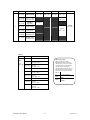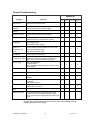
1
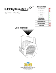
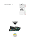
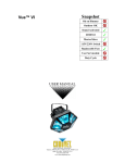
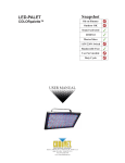
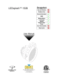
Snapshot
LEDsplash™2
Ok on Dimmer
Outdoor OK
Sound Activated
DMX512
Master/Slave
Autoswitching
Transformer
Replaceable Fuse
User Serviceable
Duty Cycle
USER MANUAL
Chauvet, 3000 N 29th Ct, Hollywood, FL 33020 U.S.A.
(800) 762-1084 – (954) 929-1115
FAX (954) 929-5560
www.chauvetlighting.com
TABLE OF CONTENTS
1. BEFORE YOU BEGIN................................................................................................................................ 3
WHAT IS INCLUDED......................................................................................................................................... 3
UNPACKING INSTRUCTIONS ............................................................................................................................. 3
AC POWER ................................................................................................................................................... 3
CONTACT US ................................................................................................................................................. 3
SAFETY INSTRUCTIONS ................................................................................................................................... 4
2. INTRODUCTION ........................................................................................................................................ 5
FEATURES..................................................................................................................................................... 5
DMX CHANNEL SUMMARY .............................................................................................................................. 5
PRODUCT OVERVIEW ..................................................................................................................................... 6
3. SETUP ........................................................................................................................................................ 7
FUSE REPLACEMENT ...................................................................................................................................... 7
FIXTURE LINKING ........................................................................................................................................... 7
Data Cabling ........................................................................................................................................... 7
DMX Data Cable............................................................................................................................... 7
Cable Connectors ............................................................................................................................. 8
3-Pin to 5-Pin Conversion Chart ....................................................................................................... 8
SETTING UP A DMX SERIAL DATA LINK ............................................................................................................ 8
MASTER/SLAVE FIXTURE LINKING .................................................................................................................... 9
MOUNTING .................................................................................................................................................... 9
Orientation ........................................................................................................................................ 9
Rigging ............................................................................................................................................. 9
4. OPERATING INSTRUCTIONS..................................................................................................................10
OPERATION ..................................................................................................................................................10
Stand-Alone Mode (Sound-Active, Auto Mode): ....................................................................................10
Master/Slave Mode (Master Sound, Master Auto): ................................................................................10
Dipswitch Options ............................................................................................................................11
DMX Mode .............................................................................................................................................11
DMX CHANNEL VALUES ................................................................................................................................11
GENERAL TROUBLESHOOTING ........................................................................................................................13
TECHNICAL SUPPORT ....................................................................................................................................14
5. APPENDIX.................................................................................................................................................14
DMX PRIMER ...............................................................................................................................................14
GENERAL MAINTENANCE ...............................................................................................................................15
RETURNS PROCEDURE ..................................................................................................................................15
CLAIMS ........................................................................................................................................................15
TECHNICAL SPECIFICATIONS ..........................................................................................................................16
LEDSplash 2 User Manual
2
2008-01-22/09:14
1. BEFORE YOU BEGIN
What is included
¾
¾
¾
¾
1 x LEDSplash™ 2
Power Cord
Warranty Card
User Manual
Unpacking Instructions
Immediately upon receiving a fixture, carefully unpack the carton, check the contents to ensure that
all parts are present, and have been received in good condition. Notify the shipper immediately and
retain packing material for inspection if any parts appear damaged from shipping or the carton itself
shows signs of mishandling. Save the carton and all packing materials. In the event that a fixture
must be returned to the factory, it is important that the fixture be returned in the original factory box
and packing.
AC Power
This fixture has an auto-switching power supply that can accommodate a wide range of input
voltages. The only thing necessary to do before powering on the unit is to make sure the line voltage
you are applying is within the range of accepted voltages. This fixture will accommodate between
100V and 240V AC. All fixtures must be powered directly off a switched circuit and cannot be run off a
rheostat (variable resistor) or dimmer circuit, even if the rheostat or dimmer channel is used solely for
a 0% to 100% switch.
Contact Us
World Wide
General Information
Chauvet Lighting
th
3000 North 29 Court
Hollywood, FL 33020
voice: 954.929.1115
fax:
954.929.5560
toll free: 800.762.1084
Technical Support
Chauvet Lighting
th
3000 North 29 Court
Hollywood, FL 33020
voice: 954.929.1115 (Press 4)
fax:
954.929.5560 (Attention: Service)
World Wide Web
www.chauvetlighting.com
LEDSplash 2 User Manual
3
2008-01-22/09:14
Safety Instructions
Please read these instructions carefully, which includes important
information about the installation, usage and maintenance of this
product.
•
•
•
•
•
•
•
•
•
•
•
•
•
•
Caution!
Please keep this User Guide for future consultation. If you sell the unit to another user, be sure that
they also receive this instruction booklet.
Always make sure that you are connecting to the proper voltage, and that the line voltage you are
connecting to is not higher than that stated on the decal or rear panel of the fixture.
This product is intended for indoor use only!
To prevent risk of fire or shock, do not expose fixture to rain or moisture. Make sure there are no
flammable materials close to the unit while operating.
The unit must be installed in a location with adequate ventilation, at least 20in (50cm) from adjacent
surfaces. Be sure that no ventilation slots are blocked.
Always disconnect from power source before servicing or replacing fuse and be sure to replace with
same fuse size and type.
Secure fixture to fastening device using a safety chain. Never carry the fixture solely by its head. Use
its carrying handles.
Maximum ambient temperature (Ta) is 104°F (40°C). Do not operate fixture at temperatures higher
than this.
In the event of a serious operating problem, stop using the unit immediately. Never try to repair the
unit by yourself. Repairs carried out by unskilled people can lead to damage or malfunction. Please
contact the nearest authorized technical assistance center. Always use the same type spare parts.
Don’t connect the device to a dimmer pack.
Make sure the power cord is never crimped or damaged.
Never disconnect the power cord by pulling or tugging on the cord.
Avoid direct eye exposure to the light source while it is on.
Do not daisy chain power to more than 8 units.
There are no user serviceable parts inside the unit. Do not open the housing or
attempt any repairs yourself. In the unlikely event your unit may require service,
please contact CHAUVET at: 954-929-1115.
LEDSplash 2 User Manual
4
2008-01-22/09:14
2. INTRODUCTION
Features
•
•
•
•
•
6-channel DMX-512 LED wash light
Blackout/static/dimmer/strobe
Static colors and RGB color mixing with or without DMX controller
Built-in automated programs via master/slave or DMX
Built-in sound activated programs via master/slave or DMX
Ad d i t i o n a l F e a t u r e s
•
•
High-power, 1W (350mA) LEDs
Linkable with LED Shadow™, LED Shadow™ 2, LED Techno Strobe™, LED
Techno Strobe™ RGB, LEDsplash™ 200B and LEDsplash™ 2 in stand alone
DMX Channel Summary
1
2
3
4
5
6
Red
000~255
Green
000~255
Blue
000~255
Strobe
000~255
Dimmer
000~255
RGB
000~029
Pulse
030~119
No
(Slow>Fast) Function
Color Macros
120~149
RGB Chase
150~179
Chase Speed
000~255
Color Change
180~209
Color Change
w/ fade
210~239
Program
Speed
000~255
Sound
240~255
Color
Macro
000~255
For a detailed view of DMX values turn to the Appendix section in this manual. Control
mode parameters are set by DMX values in Channel # 1.
LEDSplash 2 User Manual
5
2008-01-22/09:14
Product Overview
Mounting
Bracket
Sound
Sensitivity
Knob
Music/Auto
Switch
Microphone
Dipswitches
DMX
Output
Connector
DMX Input
Connector
LEDSplash 2 User Manual
Power
Connector and
Fuse Holder
6
Power Output
(max 8 units)
LEDsplash 2 only!
2008-01-22/09:14
3. SETUP
Disconnect the power cord before replacing a fuse and always
replace with the same type fuse.
Fuse Replacement
With a flat head screwdriver wedge the fuse
holder out of its housing. Remove the damaged
fuse from its holder and replace with exact
same type fuse. Insert the fuse holder back in
its place and reconnect power.
The fuse is located
inside this
compartment.
Remove using a flat
head screwdriver.
Fixture Linking
You will need a serial data link to run light shows of one or more fixtures using a DMX-512 controller
or to run synchronized shows on two or more fixtures set to a master/slave operating mode. The
combined number of channels required by all the fixtures on a serial data link determines the number
of fixtures the data link can support.
Important:
Fixtures on a serial data link must be daisy chained in one single line. To comply with the EIA-485
standard no more than 32 devices should be connected on one data link. Connecting more than 32
fixtures on one serial data link without the use of a DMX optically-isolated splitter may result in
deterioration of the digital DMX signal.
Maximum recommended serial data link distance: 500 meters (1640 ft.)
Maximum recommended number of fixtures on a serial data link: 32 fixtures
Data Cabling
To link fixtures together you must obtain data cables. You can purchase CHAUVET-certified DMX
cables directly from a dealer/distributor or construct your own cable. If you choose to create your own
cable please use data-grade cables that can carry a high quality signal and are less prone to
electromagnetic interference.
D MX DA TA CAB LE
Use a Belden© 9841 or equivalent cable which meets the specifications for EIA RS-485 applications.
Standard microphone cables cannot transmit DMX data reliably over long distances. The cable will
have the following characteristics:
2-conductor twisted pair plus a shield
Maximum capacitance between conductors – 30 pF/ft.
Maximum capacitance between conductor and shield – 55 pF/ft.
Maximum resistance of 20 ohms / 1000 ft.
Nominal impedance 100 – 140 ohms
LEDSplash 2 User Manual
7
2008-01-22/09:14
CAB LE C ONN ECTORS
Cabling must have a male XLR connector on one end and a female XLR connector on the other end.
1
3
2
DMX connector configuration
COMMON
INPUT
1
3
2
CAUTION
1
3
2
DMX +
DMX
-
Resistance 120
ohm 1/4w between
pin 2 (DMX -) and
pin 3 (DMX +) of
the last fixture.
OUTPUT
Termination reduces signal errors and
to avoid signal transmission problems
and interference, it is always
advisable to connect a DMX signal
terminator.
Do not allow contact between the common and the fixture’s chassis ground. Grounding the common
can cause a ground loop, and your fixture may perform erratically. Test cables with an ohm meter to
verify correct polarity and to make sure the pins are not grounded or shorted to the shield or each other.
3-PIN TO 5- PIN CON VER SION CHAR T
Note!
If you use a controller with a 5 pin DMX output connector, you will need to use a 5 pin to 3 pin adapter.
CHAUVET Model No: DMX5M, or DMX5F.
The chart below details a proper cable conversion:
3 PIN TO 5 PIN CONVERSION CHART
Conductor
3 Pin Female (output)
5 Pin Male (Input)
Ground/Shield
Pin 1
Pin 1
Data ( - ) signal
Pin 2
Pin 2
Data ( + ) signal
Pin 3
Pin 3
Do not use
Do not use
Do not use
Do not use
Setting up a DMX Serial Data Link
Universal DMX Controller
1. Connect the (male) 3 pin connector side of the DMX cable to the output (female) 3 pin connector
of the controller.
2. Connect the end of the cable coming from the controller which will have a (female) 3 pin connector
to the input connector of the next fixture consisting of a (male) 3 pin connector.
3. Then, proceed to connect from the output as stated above to the input of the following fixture and
so on.
CHAUVET Certified DMX Data Cables
Order Code
Description
DMX1.5
DMX Cable 1.5m/4.9ft
DMX4.5
DMX Cable 4.5m/14.8ft
DMX10
DMX Cable 10m/32.8ft
This drawing provides a
general illustration of the
DMX Input/Output panel of
a lighting fixture.
Continue the link
LEDSplash 2 User Manual
8
2008-01-22/09:14
Master/Slave Fixture Linking
1. Connect the (male) 3 pin connector side of the DMX cable to the output (female) 3 pin connector
of the first fixture.
2. Connect the end of the cable coming from the first fixture which will have a (female) 3 pin
connector to the input connector of the next fixture consisting of a (male) 3 pin connector. Then,
proceed to connect from the output as stated above to the input of the following fixture and so on.
Often, the setup for Master-Slave
and Standalone operation requires
that the first fixture in the chain be
initialized for this purpose via either
settings in the control panel or DIPswitches. Secondarily, the fixtures
that follow may also require a slave
setting. Please consult the
“Operating Instructions” section in
this manual for complete instructions
for this type of setup and
configuration.
Mounting
ORIENTATION
This fixture may be mounted in any position provided there is adequate room for ventilation.
R IG G IN G
Hanging Clamp
It is important never to obstruct the fan or vents pathway. Mount the
fixture using, a suitable “C” or “O” type clamp. Adjust the angle of the
fixture by loosening both knobs and tilting the fixture. After finding the
desired position, retighten both knobs.
•
•
•
When selecting installation location, take into consideration lamp
replacement access and routine maintenance.
Safety cables should always be used.
Never mount in places where the fixture will be exposed to rain, high
humidity, extreme temperature changes or restricted ventilation.
LEDSplash 2 User Manual
9
Note!
Clamp is sold separately.
2008-01-22/09:14
4. OPERATING INSTRUCTIONS
Operation
Stand-Alone Mode (Sound-Active, Auto Mode):
This mode allows a single unit to run to the beat of the music, or the unit will auto change in Auto
Mode.
1.
Set all dipswitches on the unit to the “Off” position and the unit will run its built in color change
program.
OPTIONS
- Set Music/Auto switch to Music and for sound-activated triggering of the program
- Set Music/Auto switch to Auto then use the rotary dial to adjust speed of the program
- See below under Dipswitch Options for additional program settings
Master/Slave Mode (Master Sound, Master Auto):
The Master/Slave mode will allow you to link up to as many units you want in a daisy chain fashion. In
this mode, the first unit in the daisy chain will automatically command all other units following.
1. Connect all LEDsplash™2 units in a daisy chain fashion as described in the section following.
2. Dipswitch settings on slave fixtures are not required and will have no affect.
3. Set all dipswitches on the Master unit to the “Off” position and the unit will run its built in color
change program.
OPTIONS
- Set Music/Auto switch to Music and for sound-activated triggering of the program
- Set Music/Auto switch to Auto then use the rotary dial to adjust speed of the program
- See below under Dipswitch Options for additional program settings
LEDsplash 2 User Manual
10
2008-01-22/09:14
D I P SW ITCH O P T IONS
FUNCTIONS
DIPSWITCHES ( ON )
Color change
program
Red LEDs
Green LEDs
Blue LEDs
“User Color”
NOTES & DESCRIPTION
None
1
Music/Auto switch
Music: Sound Activated, Rotary knob sets sound sensitivity
Auto: Rotary knob sets speed of program
Low Intensity
2
Medium Intensity
3
Full Intensity
4
Low Intensity
5
Medium Intensity
6
Full Intensity
7
Low Intensity
8
Medium Intensity
9
Full Intensity
Any combination of Red, Green and For example Dipswitch 9 and 3 ON creates a Pink color
Blue LED intensity to create custom
color.
DMX Mode
This mode allows the unit to be controlled by any universal DMX controller. If you are unfamiliar with
DMX, please read the DMX Primer on page 15.
1)
A working DMX-512 signal source plugged into the LEDsplash™ 2 activates the DMX mode.
DMX Channel Values
NOTE!
Please read all instructions carefully on fixture DMX control mode and addressing.
DMX channels 2, 3, 4, 5 and 6 functions are determined by the current settings of channel 1. For
example, while Channel 1 is set between 000 and 029 the following conditions will apply;
i.
ii.
iii.
iv.
v.
LEDsplash 2 User Manual
Channel 2 will control the Red LEDs
Channel 3 will control the Green LEDs
Channel 4 will control the Blue LEDs
Channel 5 will control Strobing
Channel 6 will control the Dimmer
11
2008-01-22/09:14
CHANNEL
1
VALUE
FUNCTION
CH 2
CH 3
CH 4
CH 5
000 Ù 029
RGB Control Mode
Red
000 Ù 255
Green
000 Ù 255
Blue
000 Ù 255
Strobe
000 Ù 255
030 Ù 059
060 Ù 119
Pulse Strobe
Pulse ( 0 <-> 100% )
Pulse ( 100 <-> 0% )
120 Ù 149
Color Macro
Color Macros
150 Ù 179
R,G,B Chase
RGB Chase pattern
180 Ù 209
Automatic
Color Change
210 Ù 239
Automatic (Fade)
Color Change w fade
240 Ù 255
CH 6
Speed
000 Ù 255
See Table 1.1
Dimmer
000 Ù 255
Speed
000 Ù 255
Sound Activated
Music/Auto switch
must be set to Music
Table 1.1
MODE
CH 2
DESCRIPTION
Color
Macro
000 Ù 016
Red
017 Ù 056
Red ( Full )
Green: ( 0% ~ 100% )
057 Ù 094
Green (Full
Red: ( 100% ~ 0% )
095 Ù 096
Green
097 Ù 136
Green ( Full )
Blue: ( 0% ~ 100% )
137 Ù 174
Blue ( Full )
Green: ( 100% ~ 0% )
175 Ù 176
Blue
177 Ù 216
Blue ( Full )
Red: ( 0% ~ 100% )
217 Ù 255
Blue ( Full )
Red ( Full )
Green: ( 0% ~ 100% )
Ch 1
120 Ù 149
LEDsplash 2 User Manual
Music/Auto Switch
Note! Regardless of DMX
controller operated use, when the
LEDsplash 2 is set to run in Sound
Activated mode, you should make
sure that all units are properly
switched to Music and that you have
adjusted the rotary dial to optimize
the sound level response of the unit.
SWITC
ROTARY FUNCTION
H
Adjusts speed of built in
AUTO
program
Adjusts sound sensitivity of
MUSIC
built in Mic.
12
2008-01-22/09:14
General Troubleshooting
Applies to
Symptom
Solution(s)
Lights
Foggers
& Snow
Controllers
Dimmers
& Chaser
Auto shut off
Check fan thermal switch reset
9
Beam is very dim or
not bright
Clean optical system or replace lamp
Check 220/110v switch for proper setting
9
Breaker/Fuse keeps
blowing
Check total load placed on device
Chase is too slow
Check users manual for speed adjustment
9
9
9
Device has no power
Check for power on Mains.
Check device’s fuse. (internal and/or external)
9
9
9
Fixture is not
responding
Check DMX Dip switch settings for correct addressing
Check DMX cables
Check polarity switch settings
9
Fixture is on but
there is no
movement to the
audio
Make sure you have the correct audio mode on the
control switches. If audio provided via ¼” jack, make
sure a live audio signal exists
Adjust sound sensitivity knob
9
9
9
Lamps cuts off
sporadically
Possible bad lamp or fixture is overheating.
Lamp may be at end of its life.
9
Light will not come
on after power failure
Some discharge lamps require a cooling off period
before the electronics in the fixture can kick start it
again, wait 5 to 10 minutes before powering up
9
Loss of signal
Use only DMX cables
Install terminator
Note: Keep DMX cables separated from power cables
or black lights.
9
9
9
Moves slow
Check 220/110v switch for proper setting
9
No flash
Re-install bulb, may have shifted in shipping
9
No laser output
Bounce mirror motor may have shifted during shipping,
readjust
9
No light output
Check slip ring & brushes for contact
Install bulb
Call service technician
9
Relay will not work
Check reset switch
Check cable connections
Remote does not
work
Make sure connector is firmly connected to device
9
Stand alone mode
All Chauvet lighting fixtures featuring stand-alone
functions do not require additional settings, simply
power the fixture and it will automatically enter into this
mode
9
9
9
9
9
If you still have a problem after trying the above solutions, please contact CHAUVET Technical
Support at the location on the next page.
LEDsplash 2 User Manual
13
2008-01-22/09:14
Technical Support
Address: Service Dept.
3000 N 29th Ct, Hollywood, FL 33020 (U.S.A.)
Support (Email): [email protected]
Telephone: (954) 929-1115 - (Press 4)
Fax: (954) 929-5560 - (Attention: Service)
Website: http://www.chauvetlighting.com
5. APPENDIX
DMX Primer
There are 512 channels in a DMX-512 connection. Channels may be assigned in any manner. A
fixture capable of receiving DMX 512 will require one or a number of sequential channels. The user
must assign a starting address on the fixture that indicates the first channel reserved in the controller.
There are many different types of DMX controllable fixtures and they all may vary in the total number
of channels required. Choosing a start address should be planned in advance. Channels should
never overlap. If they do, this will result in erratic operation of the fixtures whose starting address is
set incorrectly. You can however, control multiple fixtures of the same type using the same starting
address as long as the intended result is that of unison movement or operation. In other words, the
fixtures will be slaved together and all respond exactly the same.
DMX fixtures are designed to receive data through a serial Daisy Chain. A Daisy Chain connection is
where the DATA OUT of one fixture connects to the DATA IN of the next fixture. The order in which
the fixtures are connected is not important and has no effect on how a controller communicates to
each fixture. Use an order that provides for the easiest and most direct cabling. Connect fixtures
using shielded two conductor twisted pair cable with three pin XLR male to female connectors. The
shield connection is pin 1, while pin 2 is Data Negative (S-) and pin 3 is Data positive (S+). CHAUVET
carries 3-pin XLR DMX compliant cables, DMX-10 (33’), DMX-4.5 (15’) and DMX-1.5 (5’)
LEDsplash 2 User Manual
14
2008-01-22/09:14
General Maintenance
To maintain optimum performance and minimize wear fixtures should be cleaned frequently. Usage
and environment are contributing factors in determining frequency. As a general rule, fixtures should
be cleaned at least twice a month. Dust build up reduces light output performance and can cause
overheating. Be sure to power off fixture before conducting maintenance.
Unplug fixture from power. Use a vacuum or air compressor and a soft brush to remove dust
collected on external vents and internal components. Clean all glass when the fixture is cold with a
mild solution of glass cleaner or Isopropyl Alcohol and a soft lint free cotton cloth or lens tissue. Apply
solution to the cloth or tissue and drag dirt and grime to the outside of the lens. Gently polish optical
surfaces until they are free of haze and lint.
The cleaning of internal and external optical lenses and/or mirrors must be carried out periodically to
optimize light output. Cleaning frequency depends on the environment in which the fixture operates:
damp, smoky or particularly dirty surrounding can cause greater accumulation of dirt on the unit’s
optics. Clean with soft cloth using normal glass cleaning fluid. - Always dry the parts carefully. - Clean
the external optics at least every 20 days. Clean the internal optics at least every 30/60 days.
Returns Procedure
Returned merchandise must be sent prepaid and in the original packing, call tags will not be issued.
Package must be clearly labeled with a Return Merchandise Authorization Number (RA #). Products
returned without an RA # will be refused. Call CHAUVET and request RA # prior to shipping the
fixture. Be prepared to provide the model number, serial number and a brief description of the cause
for the return. Be sure to properly pack fixture, any shipping damage resulting from inadequate
packaging is the customer’s responsibility. CHAUVET reserves the right to use its own discretion to
repair or replace product(s). As a suggestion, proper UPS packing or double-boxing is always a safe
method to use.
Note:
If you are given an RA #, please include the following information on a piece of paper
inside the box:
1)
Your name
2)
Your address
3)
Your phone number
4)
The RA #
5)
A brief description of the symptoms
Claims
Damage incurred in shipping is the responsibility of the shipper; therefore the damage must be
reported to the carrier upon receipt of merchandise. It is the customer's responsibility to notify and
submit claims with the shipper in the event that a fixture is damaged due to shipping. Any other claim
for items such as missing component/part, damage not related to shipping, and concealed damage,
must be made within seven (7) days of receiving merchandise.
LEDsplash 2 User Manual
15
2008-01-22/09:14
Technical Specifications
WEIGHT & DIMENSIONS
Length............................................................................................................................. 9.5 in (241 mm)
Width ..................................................................................................................................9 in (229 mm)
Height ............................................................................................................................. 6.8 in (171 mm)
Weight .............................................................................................................................. 4.7 lbs (2.1 kg)
POWER
Autoswitching Power Supply ................................................................................ 100V – 240V 50/60Hz
Fuse......................................................................................................20mm Glass 2A 250V Fast Blow
Power Consumption at 120V 60Hz ....................................................................... 19W (0.3A) operating
Inrush Power .................................................................................................................................... 1.4A
Power Factor .....................................................................................................................................0.63
LIGHT SOURCE
LED................................................................................................ 24 (8 red, 8 green, 8 blue) 50,000hrs
PHOTO OPTIC
Beam Angle ..................................................................................................................................... 11.8°
Field Angle.......................................................................................................................................... 22°
Illuminance at 1m ...................................................................................................................... 5,627 lux
THERMAL
Maximum ambient temperature...........................................................................................104°F (40°C)
CONTROL & PROGRAMMING
Data input ................................................................................................ locking 3-pin XLR male socket
Data output ........................................................................................... locking 3-pin XLR female socket
Data pin configuration ..............................................................................pin 1 shield, pin 2 (-), pin 3 (+)
Protocols........................................................................................................................ DMX-512 USITT
DMX Channels .......................................................................................................................................6
ORDERING INFORMATION
LEDSplash 2.................................................................................................................... LED-SPLASH2
WARRANTY INFORMATION
Warranty .............................................................................................................. 2-year limited warranty
LEDsplash 2 User Manual
16
2008-01-22/09:14