1
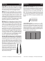
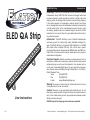
ELED QA Strip Introduction
Unpacking: Thank you for purchasing the ELED QA Strip by Elation
ELED QA Strip
Professional®. Every ELED QA Strip has been thoroughly tested and
has been shipped in perfect operating condition. Carefully check the
shipping carton for damage that may have occurred during shipping.
If the carton appears to be damaged, carefully inspect your fixture
for any damage and be sure all accessories necessary to operate the
unit has arrived intact. In the case damage has been found or parts
are missing, please contact our customer support number for further
instructions. Do not return this unit to your dealer without first contacting customer support.
Introduction: The ELED QA Strip is part of Elation Professionals®
continuing pursuit for creating high quality affordable intelligent fixtures. The ELED QA Strip is a powerful DMX intelligent 4-in-1 RGBA
(Red, Green, Blue, & Amber) LED strip. This unit can has 4 operating modes; Macro mode, Program mode, RGBA mode, and DMX controlled. This unit can be used as a single, stand alone unit or used in a
master-slave configuration.
Customer Support: ©Elation® provides a customer support line, to
provide set up help and to answer any question should you encounter
problems during your set up or initial operation. You may also visit us
on the web at www.elationlighting.com for any comments or suggestions. Service Hours are Monday through Friday 8:00 a.m. to 4:30 p.m.
Pacific Standard Time.
Voice:
(323) 582-3322
Fax: (323) 832-9142
E-mail: [email protected]
Warning! To prevent or reduce the risk of electrical shock or fire, do
not expose this unit to rain or moisture.
Caution! There are no user serviceable parts inside this unit. Do not
User Instructions
12/12
attempt any repairs yourself, doing so will void your manufactures warranty. In the unlikely event your unit may require service please contact
©Elation customer support.
PLEASE recycle the shipping carton when ever possible.
Elation Professional - www.elationlighting.com - ELED QA Strip Instruction Manual Page 2
ELED QA Strip General Instructions
To optimize the performance of this product, please read these
operating instructions carefully to familiarize yourself with the basic
operations of this unit. These instructions contain important safety
information regarding the use and maintenance of this unit. Please
keep this manual with the unit, for future reference.
ELED QA Strip Features
•
•
•
•
•
•
Multi-Colors
Built in Microphone
Four Operating Modes
68 Color Macros
DMX-512 protocol
9 DMX Modes: 1 Channel Mode, 2 Channel Mode, 4 Channel Mode, 5 Channel Mode, 7 Channel Mode, 8 Channel Mode, 36 Channel Mode, 54 Channel Mode, & 72 Channel Mode.
• Pixel Direction Control: The direction in which the pixels light up can be reversed so that the pixels can light up at either end of the bar. This feature is used with 36 DMX Channel mode, 54 DMX Channel mode, and 72 DMX Channel mode. This feature is also used with some built-in programs under Program Mode.
ELED QA Strip
Warranty Registration
The ELED QA Strip carries a two year limited warranty. Please fill out
the enclosed warranty card to validate your purchase. All returned
service items whether under warranty or not, must be freight pre-paid
and accompany a return authorization (R.A.) number. The R.A. number
must be clearly written on the outside of the return package. A brief
description of the problem as well as the R.A. number must also be
written down on a piece of paper included in the shipping carton. If
the unit is under warranty, you must provide a copy of your proof of
purchase invoice. You may obtain a R.A. number by contacting our
customer support team on our customer support number. All packages returned to the service department not displaying a R.A. number
on the outside of the package will be returned to the shipper.
Elation Professional - www.elationlighting.com - ELED QA Strip Instruction Manual Page 3
ELED QA Strip
Safety Precautions
•To reduce the risk of electrical shock or fire, do not expose this unit rain or moisture
•Do not spill water or other liquids into or on to your unit.
•Do not attempt to operate this unit if the power cord hasbeen
frayed or broken. Do not attempt to remove or break off the ground
prong from the electrical cord. This prong is used to reduce the risk of electrical shock and fire in case of an internal short.
•Disconnect from main power before making any type of connection.
• Do not remove the cover under any conditions. There are no user serviceable parts inside.
•Never operate this unit when it’s cover is removed.
•Never plug this unit in to a dimmer pack
•Always be sure to mount this unit in an area that will allow proper ventilation. Allow about 6” (15cm) between this device and a wall.
•Do not attempt to operate this unit, if it becomes damaged.
•This unit is intended for indoor use only, use of this product out`
doors voids all warranties.
•During long periods of non-use, disconnect the unit’s main power.
•Always mount this unit in safe and stable matter.
•Power-supply cords should be routed so that they are not likely to
be walked on or pinched by items placed upon or against them, paying particular attention to the point they exit from the unit.
• Cleaning -The fixture should be cleaned only as recommended by the manufacturer. See page 19 for cleaning details.
•Heat -The appliance should be situated away from heat sources such as radiators, heat registers, stoves, or other appliances (including amplifiers) that produce heat.
•The fixture should be serviced by qualified service personnel when:
A. The power-supply cord or the plug has been damaged.
B. Objects have fallen, or liquid has been spilled into the appliance.
C. The appliance has been exposed to rain or water.
D. The appliance does not appear to operate normally or exhibits a marked change in performance.
Elation Professional - www.elationlighting.com - ELED QA Strip Instruction Manual Page 4
SOUND
REMOTE
CONTROL
INPUT
INPUT
OUTPUT
ELED QA Strip
Set Up
Power Supply: The Elation ELED QA Strip contains an automatic
voltage switch, which will auto sense the voltage when it is plugged
into the power source. With this switch there is no need to worry about
the correct power voltage, this unit can be plugged in anywhere.
DMX512
POWER
DMX+,DMX-,COMMON
DMX-512: DMX is short for Digital Multiplex. This is a universal pro-
tocol used by most lighting and controller manufactures as a form of
communication between intelligent fixtures and controllers. A DMX
controller sends DMX data instructions from the controller to the fixture. DMX data is sent as serial data that travels from fixture to fixture
COMMON
via the DATA “IN” and DATA “OUT” XLR terminals located on all DMX
DMX +
DMX512 OUT
3-PIN XLR
fixtures (most controllers only have a DATA “OUT” terminal).
DMX DMX Linking: DMX is a language allowing all makes and models of
different manufactures to be linked together and operate from a single
controller, as long as all fixtures and the controller are DMX compliant. To ensure proper DMX data transmission, when using several
DMX fixtures try to use the shortest cable path possible. The order
in which fixtures are connected in a DMX line does not influence the
DMX addressing. For example; a fixture assigned a DMX address of 1
may be placed anywhere in a DMX line, at the beginning, at the end,
or anywhere in the middle. When a fixture is assigned a DMX address
of 1, the DMX controller knows to send DATA assigned to address 1
to that unit, no matter where it is located in the DMX chain.
1
2
REMOTE
CONTROL
INPUT
SOUND
3
Data Cable (DMX Cable) Requirements (For DMX Operation):
The ELED QA Strip has 9 DMX Channel Modes. The DMX address is
set electronically using the controls on the rear panel of the unit. Your
unit and your DMX controller require a approved DMX-512 110 Ohm
Data cable for data input and data output. We recommend Accu-Cable
DMX cables. If you are making your own cables, be sure to use standard 110-120 Ohm shielded cable (This cable may
be purchased at almost all professional sound and
lighting stores). Your cables should be made with
a male and female XLR connector on either end of
the cable. Also remember that DMX cable must be
daisy chained and cannot be split.
INPUT
OUTPUT
REMOTE
CONTROL
INPUT
SOUND
INPUT
OUTPUT
ELED QA Strip
Set Up
Special Note: Line Termination. When longer runs of cable are
POWER
POWER
used, you may need to use a terminator on the last unit to avoid erratic
behavior. A terminator is a 110-120 ohm 1/4 watt resistor which is connected between pins 2 and 3 of a male XLR connector (DATA + and
DATA -). This unit is inserted in the female XLR connector of the last
unit in your daisy chain to terminate the line. Using a cable terminator
(ADJ part number Z-DMX/T) will decrease the possibilities of erratic
behavior.
3
1
2
DMX512 IN
3-PIN XLR
3
1
2
Termination reduces signal errors and
avoids signal transmission problems
and interference. It is always advisable
to connect a DMX terminal, (Resistance
120 Ohm 1/4 W) between PIN 2 (DMX-)
and PIN 3 (DMX +) of the last fixture.
5-Pin XLR DMX Connectors. Some manufactures use 5-pin DMX-
512 data cables for DATA transmission in place of 3-pin. 5-pin DMX
fixtures may be implemented in a 3-pin DMX line. When inserting
standard 5-pin data cables in to a 3-pin line a cable adaptor must be
used, these adaptors are readily available at most electric stores. The
chart below details a proper cable conversion.
3-Pin XLR to 5-Pin XLR Conversion
Conductor
3-Pin XLR Female (Out)
5-Pin XLR Male (In)
Ground/Shield
Pin 1
Pin 1
Data Compliment (- signal)
Pin 2
Pin 2
Data True (+ signal)
Pin 3
Pin 3
Not Used
Do Not Use
Not Used
Do Not Use
Figure 1
Elation Professional - www.elationlighting.com - ELED QA Strip Instruction Manual Page 5
Elation Professional - www.elationlighting.com - ELED QA Strip Instruction Manual Page 6
ELED QA Strip
Operating Instructions
LED Display Backlight On/Off:
To set the LED display to turn off after 10 seconds, press the MODE
button until “Disperm BackLight” is displayed. Either “On” or “Off” will
be displayed. Press the UP or DOWN button so that “Off” is displayed,
the display will now turn off after 10secs. Press any button for at least
5secs. to turn the display on again. Be advised though that the display
will turn off automatically after 10 seconds of inactivity. To make the
backlight display stay on at all times, press the UP of DOWN button so
that “On” is displayed.
Operating Modes:
You can use the ELED QA Strip in four ways:
• Macro Mode - There are 68 color macros to choose from.
• Program Mode - There are 15 built in programs and sound active mode to choose from.
• RGBA mode - Control the intensity of all four colors adjusting the intensity to your desire.
• DMX control mode - This function will allow you to control each
individual fixtures traits with a standard DMX 512 controller such as
as the Elation® Show Designer™.
Macro Mode:
1. Plug the fixture in and press the MODE button until “Color Macro” is displayed.
2. There are 68 macros to choose from. Select your desired macro by pressing the UP and DOWN buttons.
Fade Program: This mode is used in conjunction with the RGBA
mode.
1. To run a fade program first create your desired color in RGBA mode. After you have created your color press the MODE button until “Program Fade Speed” is displayed.
2. Press the UP or DOWN buttons to make the adjustmetns. “Speed 0” is the slowest speed, “Speed 15” the fastest speed.
Program Mode:
1. Plug the fixture in and press the MODE button until “Color Program” is displayed.
2. There are 15 built-in programs to choose from or you can select “sound active” to run the unit by sound. Select your desired program by pressing the UP and DOWN buttons. You can set your program Elation Professional - www.elationlighting.com - ELED QA Strip Instruction Manual Page 7
ELED QA Strip
Operating Instructions
speed by following the next set of instructions. The direction of cer-
tain programs can also be changed under Directions Set.
Direction Set: This feature is used in conjunction with 36 DMX
Channel mode, 54 DMX Channel mode and 72 DMX Channel mode. The
direction in which the pixels light up can be reversed so that the pixel line
up can start at either end of the bar. This feature is useful when the unit
is installed in a reversed orientation so the unit itself does not have to
be uninstalled and reversed. Example: When using 36 Channel mode,
Channel 1 LEDs 1 & 2 can start at either end of the bar depending
on the “Direction Set” set up.
1. To change the starting direction press the MODE button until “Direction Set” is displayed.
2. Press the UP or DOWN buttons to select “Positive” in which the pix-
els light up from right to left, or “Negative” in which the pixels will light up left to right.
Program Mode Speed Adjustment:
1. To adjust the speed of your program press the MODE button until “Color Speed” is displayed.
2. Press the UP or DOWN buttons to make the adjustmetns. “Speed 1” is the slowest speed, “Speed 16” the fastest speed.
RGBA Mode:
1. Plug the fixture in and press the MODE button until:
2. When “Single Color Red” is displayed you are in Red dimming mode. Press the UP and DOWN buttons to adjust intensity.
3. When “Single Color Green” is displayed you are in Green dimming mode. Press the UP and DOWN buttons to adjust intensity.
4. When “Single Color Blue” is displayed you are in Blue dimming mode. Press the UP and DOWN buttons to adjust intensity.
5. When “Single Color Amber” is displayed you are in White dimming mode. Press the UP and DOWN buttons to adjust intensity.
6. You can use the color macro chart on page 14 to create one of the 68 macros.
DMX Mode:
Operating through a DMX controller gives the user the freedom to create
their own programs tailored to their own individual needs. The ELED QA
Strip has 9 DMX modes: 1 Channel mode, 2 Channel mode, 4 Channel
mode, 5 Channel mode, 7 Channel mode, 8 Channel mode, 36 Channel
Elation Professional - www.elationlighting.com - ELED QA Strip Instruction Manual Page 8
ELED QA Strip
Operating Instructions
mode, 54 Channel mode, and a 72 Channel mode. See pages 11-16 for
each modes’ DMX traits.
1. This function will allow you to control each individual fixture’s traits with a standard DMX 512 controller such as the Elation® Show
Designer™ or the Elation® DMX Operator™.
2. To run your fixture in DMX mode, plug in the fixture via the XLR connections to any standard DMX controller. Select your desired DMX mode, and then press the UP or DOWN buttons to adjust the DMX
address.
3. DMX Channel Modes are as follows:
• To run the 1 Channel Mode, press the MODE button until “1 Channel DMX” is displayed. This is the DMX addressing for the 1 Channel Mode.
• To run the 2 Channel Mode, press the MODE button until “2 Channel DMX” is displayed. This is the DMX addressing for the 2 Channel Mode.
• To run the 4 Channel Mode, press the MODE button until “4
Channel DMX” is displayed. This is the DMX addressing for the 4 Channel Mode.
• To run the 5 Channel Mode, press the MODE button until “5 Channel DMX” is displayed. This is the DMX addressing for the 5 Channel Mode.
• To run the 7 Channel Mode, press the MODE button until “7 Channel DMX” is displayed. This is the DMX addressing for the 7 Channel Mode.
• To run the 8 Channel Mode, press the MODE button until “8 Channel DMX” is displayed. This is the DMX addressing for the 8 Channel Mode.
• To run the 36 Channel Mode, press the MODE button until “36 Channel DMX” is displayed. This is the DMX addressing for the 36 Channel Mode.
• To run the 54 Channel Mode, press the MODE button until “54 Channel DMX” is displayed. This is the DMX addressing for the 54 Channel Mode.
• To run the 72 Channel Mode, press the MODE button until “72 Channel DMX” is displayed. This is the DMX addressing for the 72 Channel Mode.
4. Please see pages 11-16 for DMX values and traits.
Elation Professional - www.elationlighting.com - ELED QA Strip Instruction Manual Page 9
ELED QA Strip
Master-Slave Configuration
Master-Slave Operation:
This function will allows you to link units together to run in a Master-Slave
mode. In Master-Slave operation one unit will act as the controlling unit
and the others will react to the controlling units built-in programs. Any
unit can act as a Master or as a Slave however, only one unit can be programmed to act as the “Master.”
Master-Slave Connections and Settings:
1. Daisy chain your units via the XLR connector on the rear of the unit. Use standard XLR data cables to link your units together. Remem-
ber that the Male XLR connector is the input and the Female XLR
connector is the ouput. The first unit in the chain (master) will use
the female XLR connector only. The last unit in the chain will use the
male XLR connector only.
2. Set the “Master” unit to your desired mode or operation.
3. For the “Slave” unit(s), set the display to any DMX channel mode. 4. Connect the “Slave” unit or units and they will automatically start to
follow the “Master.”
Elation Professional - www.elationlighting.com - ELED QA Strip Instruction Manual Page 10
ELED QA Strip
Channel
1
Value
0 - 255
ELED QA Strip
Channel
Value
1
0 - 255
2
0 - 255
ELED QA Strip
Channel
1
2
3
4
1 Channel Mode
Function
COLOR MACROS
PLEASE SEE COLOR MACRO CHART ON PAGE 17
2 Channel Mode
Function
COLOR MACROS
PLEASE SEE COLOR MACRO CHART ON PAGE 17
MASTER DIMMER 0% - 100%
4 Channel Mode
ELED QA Strip
Channel
1
2
3
4
5
Value
Function
0 - 255
RED
0% - 100%
0 - 255
GREEN
0% - 100%
0 - 255
BLUE
0% - 100%
2
0 - 255
AMBER
0% - 100%
3
Value
Function
0 - 255
RED
0% - 100%
0 - 255
GREEN
0% - 100%
0 - 255
BLUE
0% - 100%
0 - 255
AMBER
0% - 100%
0 - 255
MASTER DIMMER
0% - 100%
ELED QA Strip
Channel
1
4
7 Channel Mode
Value
Function
0 - 255
RED
0% - 100%
0 - 255
GREEN
0% - 100%
0 - 255
BLUE
0% - 100%
0 - 255
AMBER
0% - 100%
5
0 - 255
6
0 - 15
16 - 255
7
5 Channel Mode
0 - 255
COLOR MACROS
PLEASE SEE COLOR MACRO CHART ON PAGE 17
NOTHING
STROBING/SPEED CONTROL
MASTER DIMMER
0% - 100%
Channel 1, 2, 3, & 4 will not work, when Channel 5 is being
used.
Elation Professional - www.elationlighting.com - ELED QA Strip Instruction Manual Page 11
Elation Professional - www.elationlighting.com - ELED QA Strip Instruction Manual Page 12
ELED QA Strip
Channel
1
2
3
4
5
6
Value
0 - 255
0 - 255
0 - 255
0 - 255
0 - 255
ELED QA Strip
8 Channel Mode
Channel
Function
1
RED
0% - 100%
GREEN
0% - 100%
BLUE
0% - 100%
AMBER
0% - 100%
COLOR MACROS
2
3
4
5
PLEASE SEE COLOR MACRO CHART ON PAGE 17
STROBING/PROGRAM SPEED
0 - 15
NOTHING
16 - 255
STROBING
SLOW - FAST
1 - 255
PROGRAM SPEED SLOW - FAST
7
MODE
0 - 127
OFF
128 - 159
AUTO MIX
160 - 191
3 COLOR JUMP
192 - 223
7 COLOR JUMP
224 - 255
SOUND ACTIVE
8
MASTER DIMMER
0 - 255
0% - 100%
Channel 1, 2, 3, & 4 will not work, when Channel 5 is being
used.
When using Channel 7, Channel 6 will control the speed of the
color changing.
6
7
8
0 - 255
0 - 255
0 - 255
0 - 255
0 - 255
0 - 255
0 - 255
0 - 255
Function
RED (LED 1 & 2)
0% - 100%
GREEN (LED 1 & 2)
0% - 100%
BLUE (LED 1 & 2)
0% - 100%
AMBER (LED 1 & 2)
0% - 100%
RED (LED 3 & 4)
0% - 100%
GREEN (LED 3 & 4)
0% - 100%
BLUE (LED 3 & 4)
0% - 100%
AMBER (LED 3 & 4)
0% - 100%
*CHANNELS 9-28 THE SAME RGBA LED PATTERN CONTINUES*
*THE DIRECTION IN WHICH THE PIXELS LIGHT UP CAN BE SWITCHED USING THE DIRECTION SET FEATURE ON PAGE 8*
29
30
31
32
33
34
35
36
Elation Professional - www.elationlighting.com - ELED QA Strip Instruction Manual Page 13
Value
36 Channel Mode
0 - 255
0 - 255
0 - 255
0 - 255
0 - 255
0 - 255
0 - 255
0 - 255
RED (LED 15 & 16)
0% - 100%
GREEN (LED 15 & 16)
0% - 100%
BLUE (LED 15 & 16)
0% - 100%
AMBER (LED 15 & 16)
0% - 100%
RED (LED 17 & 18)
0% - 100%
GREEN (LED 17 & 18)
0% - 100%
BLUE (LED 17 & 18)
0% - 100%
AMBER (LED 17 & 18)
0% - 100%
Elation Professional - www.elationlighting.com - ELED QA Strip Instruction Manual Page 14
ELED QA Strip
Channel
1
2
3
4
5
6
7
8
Value
0 - 255
0 - 255
0 - 255
0 - 255
0 - 255
0 - 255
0 - 255
0 - 255
54 Channel Mode
Function
RED (LED 1)
0% - 100%
GREEN (LED 1)
0% - 100%
BLUE (LED 1)
0% - 100%
RED (LED 2)
0% - 100%
GREEN (LED 2)
0% - 100%
BLUE (LED 2)
0% - 100%
RED (LED 3)
0% - 100%
GREEN (LED 3)
0% - 100%
*CHANNELS 9-46 THE SAME RGBA LED PATTERN CONTINUES*
*THE DIRECTION IN WHICH THE PIXELS LIGHT UP CAN BE SWITCHED USING THE DIRECTION SET FEATURE ON PAGE 8*
47
48
49
50
51
52
53
54
0 - 255
0 - 255
0 - 255
0 - 255
0 - 255
0 - 255
0 - 255
0 - 255
GREEN (LED 16)
0% - 100%
BLUE (LED 16)
0% - 100%
RED (LED 17)
0% - 100%
GREEN (LED 17)
0% - 100%
BLUE (LED 17)
0% - 100%
RED (LED 18)
0% - 100%
GREEN (LED 18)
0% - 100%
BLUE (LED 18)
0% - 100%
Elation Professional - www.elationlighting.com - ELED QA Strip Instruction Manual Page 15
ELED QA Strip
Channel
Value
72 Channel Mode
Function
1
RED (LED 1)
0 - 255
0% - 100%
2
GREEN (LED 1)
0 - 255
0% - 100%
3
BLUE (LED 1)
0 - 255
0% - 100%
4
AMBER (LED 1)
0 - 255
0% - 100%
5
RED (LED 2)
0 - 255
0% - 100%
6
GREEN (LED 2)
0 - 255
0% - 100%
7
BLUE (LED 2)
0 - 255
0% - 100%
8
AMBER (LED 2)
0 - 255
0% - 100%
*CHANNELS 9-64 THE SAME RGBW PATTERN CONTINUES*
*THE DIRECTION IN WHICH THE PIXELS LIGHT UP CAN BE SWITCHED USING THE DIRECTION SET FEATURE ON PAGE 8*
65
66
67
68
69
70
71
72
0 - 255
0 - 255
0 - 255
0 - 255
0 - 255
0 - 255
0 - 255
0 - 255
RED (LED 17)
0% - 100%
GREEN (LED 17)
0% - 100%
BLUE (LED 17)
0% - 100%
AMBER (LED 17)
0% - 100%
RED (LED 18)
0% - 100%
GREEN (LED 18)
0% - 100%
BLUE (LED 18)
0% - 100%
AMBER (LED 18)
0% - 100%
Elation Professional - www.elationlighting.com - ELED QA Strip Instruction Manual Page 16
ELED QA Strip
Color Macro Chart
DMX
R
G
B
A
Black
0
0
0
0
0
DMX
R
G
B
Macro mode1
1-4
80
255
234
80
Macro mode33
129-132
255
206
143
0
Macro mode2
5-8
80
255
164
80
Macro mode34
133-136
254
177
153
0
Macro mode3
9-12
77
255
112
77
Macro mode35
137-140
254
192
138
0
Macro mode4
13-16
117
255
83
83
Macro mode36
141-144
254
165
98
0
Macro mode5
17-20
160
255
77
77
Macro mode37
145-148
254
121
0
0
Macro mode6
21-24
223
255
83
83
Macro mode38
149-152
176
17
0
0
Macro mode7
25-28
255
243
77
77
Macro mode39
153-156
96
0
11
0
Macro mode8
29-32
255
200
74
74
Macro mode40
157-160
234
139
171
0
Macro mode9
33-36
255
166
77
77
Macro mode41
161-164
224
5
97
0
Macro mode10
37-40
255
125
74
74
Macro mode42
165-168
175
77
173
0
ELED QA Strip
A
Macro mode11
41-44
255
97
77
74
Macro mode43
169-172
119
130
199
0
Macro mode12
45-48
255
71
77
71
Macro mode44
173-176
147
164
212
0
Macro mode13
49-52
255
83
134
83
Macro mode45
177-180
88
2
163
0
Macro mode14
53-56
255
93
182
93
Macro mode46
181-184
0
38
86
0
Macro mode15
57-60
255
96
236
96
Macro mode47
185-188
0
142
208
0
Macro mode16
61-64
238
93
255
93
Macro mode48
189-192
52
148
209
0
Macro mode17
65-68
196
87
255
87
Macro mode49
193-196
1
134
201
0
Macro mode18
69-72
150
90
255
90
Macro mode50
197-200
0
145
212
0
Macro mode19
73-76
100
77
255
77
Macro mode51
201-204
0
121
192
0
Macro mode20
77-80
77
100
255
77
Macro mode52
205-207
0
129
184
0
Macro mode21
81-84
67
148
255
67
Macro mode53
208-210
0
83
115
0
Macro mode22
85-88
77
195
255
87
Macro mode54
211-213
0
97
166
0
Macro mode23
89-92
77
234
255
77
Macro mode55
214-216
1
100
167
0
Macro mode24
93-96
158
255
144
144
Macro mode56
217-219
0
40
86
0
Macro mode25
97-100
255
251
153
153
Macro mode57
220-222
209
219
182
0
Macro mode26
101-104
255
175
147
147
Macro mode58
223-225
42
165
85
0
Macro mode27
105-108
255
138
186
138
Macro mode59
226-228
0
46
35
0
Macro mode28
109-112
255
147
251
147
Macro mode60
229-231
8
107
222
0
Macro mode29
113-116
151
138
255
138
Macro mode61
232-234
107
156
231
0
Macro mode30
117-120
151
147
255
147
Macro mode62
235-237
165
198
247
0
Macro mode31
121-124
138
169
255
138
Macro mode63
238-240
0
0
189
0
Macro mode32
125-128
255
255
255
255
Macro mode64
241-243
255
255
255
0
Macro mode65
244-246
255
0
0
0
Macro mode66
247-249
0
255
0
0
Macro mode67
250-252
0
0
255
0
Macro mode68
253-255
0
0
0
255
Elation Professional - www.elationlighting.com - ELED QA Strip Instruction Manual Page 17
Color
RED(LUX)
X
Y
GRE(LUX)
X
Y
Blu(LUX)
X
Y
Amber(LUX)
X
Y
TOTAL WHI(LUX)
X
Y
Photometric Chart
ELED QA STRIP
1m
863
6976
3020
1330
1886
7387
215
1399
284
1046
5870
4124
3157
3209
2276
2m
313
6975
3018
457
1887
7375
78
1401
285
349
5880
4108
1088
3183
2218
3m
158
6970
3017
223
1894
7362
36
1403
287
169
5883
4098
541
3195
2205
Elation Professional - www.elationlighting.com - ELED QA Strip Instruction Manual Page 18
ELED QA Strip
Power Cord Daisy Chain
With this feature you can connect the fixtures to one another
using the powercon input and output sockets. The quantity that
can be connected is 6 fixtures maximum. After 6 fixtures you will
need to use a new power outlet. They must be the same fixtures.
DO NOT mix fixtures.
ELED QA Strip
Fuse Replacement
First unplug the power. The fuse holder is located next to the power
inlets. Using a flat-head screw driver unscrew the fuse holder.
Remove the bad fuse and replace with a new one.
ELED QA Strip
Cleaning
Due to fog residue, smoke, and dust cleaning the internal and external optical lenses must be carried out periodically to optimize light
output.
1. Use normal glass cleaner and a soft cloth to wipe down the
outside casing.
2. Clean the external optics with glass cleaner and a soft cloth
every 20 days.
3. Always be sure to dry all parts completely before plugging
the unit back in.
Cleaning frequency depends on the environment in which the fixture
operates (i.e. smoke, fog residue, dust, dew).
ELED QA Strip
Trouble Shooting
Listed below are a few common problems the user may encounter,
with solutions.
Unit not responding to DMX:
1. Check that the DMX cables are connected properly and are wired correctly (pin 3 is “hot”; on some other DMX devices pin 2 may be ‘hot’). Also, check that all cables are connected to the right connectors; it does matter which way the inputs and outputs are connected.
Unit does not respond to sound:
1. Quiet or high pitched sounds will not activate the unit.
Elation Professional - www.elationlighting.com - ELED QA Strip Instruction Manual Page 19
ELED QA Strip
2-YEAR LIMITED WARRANTY
Warranty
A. Elation Professionals® hereby warrants, to the original purchaser, Elation Professionals® products to be free of manufacturing defects in material and workmanship
for a period of two years (730 days) from the date of purchase. This warranty shall be
valid only if the product is purchased within the United States of America, including
possessions and territories. It is the owner’s responsibility to establish the date and
place of purchase by acceptable evidence, at the time service is sought.
B. For warranty service, send the product only to the Elation Professionals® factory.
All shipping charges must be pre-paid. If the requested repairs or service (including
parts replacement) are within the terms of this warranty, Elation Professionals® will
pay return shipping charges only to a designated point within the United States. If the
entire instrument is sent, it must be shipped in its original package. No accessories
should be shipped with the product. If any accessories are shipped with the product,
Elation Professionals® shall have no liability whatsoever for loss of or damage to any
such accessories, nor for the safe return thereof.
C. This warranty is void if the serial number has been altered or removed; if the product is modified in any manner which Elation Professionals® concludes, after inspection, affects the reliability of the product; if the product has been repaired or serviced
by anyone other than the Elation Professionals® factory unless prior written authorization was issued to purchaser by Elation Professionals®; if the product is damaged
because not properly maintained as set forth in the instruction manual.
D. This is not a service contract, and this warranty does not include maintenance,
cleaning or periodic check-up. During the period specified above, Elation Professionals® will replace defective parts at its expense, and will absorb all expenses for warranty service and repair labor by reason of defects in material or workmanship. The
sole responsibility of Elation Professionals® under this warranty shall be limited to the
repair of the product, or replacement thereof, including parts, at the sole discretion
of Elation Professionals®. All products covered by this warranty were manufactured
after January 1, 1990, and bear identifying marks to that effect.
E. Elation Professionals® reserves the right to make changes in design and/or
improvements upon its products without any obligation to include these changes in
any products theretofore manufactured.
F. No warranty, whether expressed or implied, is given or made with respect to any
accessory supplied with products described above. Except to the extent prohibited
by applicable law, all implied warranties made by Elation Professionals® in connection with this product, including warranties of merchantability or fitness, are limited in
duration to the warranty period set forth above. And no warranties, whether expressed
or implied, including warranties of merchantability or fitness, shall apply to this product after said period has expired. The consumer’s and or Dealer’s sole remedy shall
be such repair or replacement as is expressly provided above; and under no circumstances shall Elation Professionals® be liable for any loss or damage, direct or consequential, arising out of the use of, or inability to use, this product.
G. This warranty is the only written warranty applicable to Elation Professionals®
Products and supersedes all prior warranties and written descriptions of warranty
terms and conditions heretofore published.
Elation Professional - www.elationlighting.com - ELED QA Strip Instruction Manual Page 20
ELED QA Strip
Notes
Elation Professional - www.elationlighting.com - ELED QA Strip Instruction Manual Page 21
ELED QA Strip
Notes
Elation Professional - www.elationlighting.com - ELED QA Strip Instruction Manual Page 22
ELED QA Strip
Specifications
Model: ELED QA Strip
SPECIFICATIONS:
Working Position: Any safe working position
Voltage*: 100V ~ 240V/47~63Hz
LED’s:
18 x 5 Watt Quad RGBA LED’s
Power Consumption:
150W
Power Cord Daisy Chain:6 Fixtures Max.
Fuse:3.15 Amp
Beam Angle:
20+50 Degrees
Weight: 21 lbs./ 9.5 kgs.
Dimensions: 40.25” (L) x 8.5” (W) x 9” (H)
1019 x 210 x 226mm
Colors:
RGBA Color Mixing
DMX Channels:
9 DMX Channel Modes: 1 Channel Mode, 2 Channel Mode, 4 Channel Mode, 5 Channel Mode, 7 Channel Mode, 8 Channel Mode, 36 Chan-
nel Mode, 54 Channel Mode, & 72 Channel Mode
Warranty:
2 Year (730 days)
*Auto Sensing Voltage: This fixture contains a automatic voltage switch,
which will auto sense the voltage when it is plugged into the power source.
Please Note: Specifications and improvements in the design of this
unit and this manual are subject to change without any prior written
notice.
Elation Professional - www.elationlighting.com - ELED QA Strip Instruction Manual Page 23
©Elation Professionals®
6122 S. Eastern Ave. Los Angeles, CA 90040 USA
Tel: 323-582-3322 Fax: 323-832-9142
Web: www.elationlighting.com E-mail: [email protected]
A.D.J. Supply Europe B.V.
Junostraat 2
6468 EW Kerkrade
Netherlands
[email protected] / www.americandj.eu
Tel: +31 45 546 85 00 / Fax: +31 45 546 85 99