1
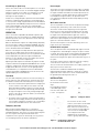
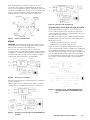
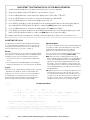
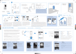
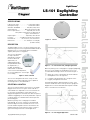
LightSaver®
LS-101 Daylighting
Controller
SPECIFICATIONS
Light Sensor range . . . . . . . . . . . . 1 to 1400 fo o tcandles
ON Setpoint range . . . . . . . . . . . . . . 1 to 850 fo o tcandles
Automatic Deadband. . . . . . . . . . . 25%, 50%, 75%, 100%
Status Indica tor . . . . . . . . . . . Multi-function green LED
Power requirements . . . . . . . . . . 12/24 VDC, min 10 mA
Total power requirements are dete r m i n e d
by the controlled device.
Output signal . . . . . . . . . . . . . . . 12/24 VDC, max 120 mA
Location . . . . . . . . . . . S u i table for dry, interior locations
Environment . . . . . . . . . 50° to 104° F, less than 90% rh
Dimensions . . . . . . . . . . . . . 2 . 4” diameter x 0.7” depth
(61mm x 17mm)
Figure 1:
LS-101
DESCRIPTION
The Watt Stopper LS-101 is an interior photosensor that
automatically turns a zone of lights ON and OFF based on
daylight levels. It is a low voltage device intended to
signal a power pack or relay panel.
The LS-101 is designed
to require minimal
adjustment at startup.
For more advanced
applications, an
onboard display and
two pushbuttons allow
for adjustments, if
needed. The display is
hidden under a removable
cover. To assist with adjustment,
the LS-101 displays the current light
level reading.
Figure 2: Cover removed
The LS-101 is designed to be either ceiling- or wallmounted. It has a wide range light sensor capable of
measuring from 1 to 1400 footcandles.
SELECTING A LOCATION
The LS-101 controls lights in areas that rece i ve enough
daylight so that the electric lights can be reduced or
switched OFF. It is important to select a location for the
LS-101 where the daylight is representa t i ve of the
daylight throughout the controlled zone. Note the path of
shadows. Daylighting co n t rol will be problematic if part of
a controlled zone is in shadows while another part has
plentiful daylight.
Figure 3:
LS-101 Field of view, sidelight application
When the primary source of daylight is a skylight (toplighting),
there are several options for mounting the LS-101. The
recommended mounting locations are shown in Figure 4.
Ideally, the sensor is mounted on the South sidew a l l
looking North across the light well.
It could also be mounted on the ceiling next to the
skylight, looking down at the floor.
A skylight may produce 5000 footcandles or more. If the
sensor is mounted so that it looks up into the skylight, the
daylight will exceed the maximum OFF setpoint of 1275fc
which is too low for this orientation.
When the primary source of daylight is a window
(sidelighting), the LS-101 is typica l ly ceiling mounted
within the daylit zone which extends 12 feet or le ss in
from the window. A good location is often between the
window and the first row of fix t u res. Figure 3 shows a
typical mounting location for a sidelit application.
Figure 4:
Copyright© 2007 Watt Stopper/Legrand
®
LS-101 Skylight application
07076r2 4/2007
Closed Loop or Open Loop
Invert output
The LS-101 can be used as a closed loop device or as an open
loop device. When the LS-101 can view both daylight and light
from the co n t rolled electric lights, it is working as a closed
loop device. When the LS-101 can only see daylight, it is
working as an open loop dev i ce.
This feature is used to control devices that require a +24 VDC
signal when the lights should be turned OFF and 0 VDC when
the lights should be turned ON. The normal operation of the
L S-101 provides a +24 VDC signal when the lights should be
turned ON, but using this feature, the operation can be
reve rsed from the Adjustment Menu Setup display to satisfy
the applica t i o n .
In both cases, having adequate separation of the ON and OFF
setpoints is important. When working in closed loop mode, it
is critical to have enough separation between the ON and OFF
settings (known as deadband) to co m p e n s a te for the reduction
of the controlled lights. If not, when the controlled lights
switch OFF, the light level will fall below the ON setpoint and
the lights switch back ON.
OPERATION
The LS-101 features adjustable ON and OFF setpoints, OFF
time delay as well as seve ral features to simplify adjustment.
For basic operation, these three paramete rs are all that may
need to be adjusted.
While the ON and OFF setpoints are independently adjustable,
the LS-101 features a built-in minimum deadband. Therefore,
these two setpoints are always automatically separa ted by at
least a minimum amount of deadband.
When the sensed light level drops below the ON setpoint for
20 seconds, the output signal switches ON. In the LS-1 0 1 ’s
default operation, this means that the LS-101 provides 24 VDC
on the output (blue wire) when the lights should be ON.
However, it is also possible to invert the output sta te. (Please
see “Invert output” for further explanation.)
Adjusting the ON setpoint also automatically adjusts the OFF
setpoint to maintain the programmed deadband. Once the ON
setpoint is changed, you can further adjust the OFF setpoint.
In applications where the LS-101 sees the lighting from the
controlled fix t u res, it is important to have the ON and OFF
setpoint separated by a deadband of at least as much as the
light provided by the controlled fix t u re.
Test Mode
The Te st mode temporarily shortens all of the time delays so
that the light level switching functions can be quickly te sted.
Te st mode is invoked in the installation process in two ways.
• A f ter either an ON or OFF setpoint has been changed, the
L S-101 remains in Test mode for one minute. The LED
blinks ON and OFF rapidly to indica te Test mode. During
this minute, te st the LS-101 operation by either blocking
the light reaching the sensor or by shining a bright light
i n to the sensor. At the end of the minute, the normal time
delays are reinsta ted.
Wall switch override
The LS-101 provides a connection for an optional low voltage,
normally-open, momentary-contact wall switch override.
This switch can be used to temporarily turn the lights ON
when the LS-101 has switched them OFF because the light
level is above the setpoint. When the wall switch is pressed,
the lights switch ON, and automatic light level control is
temporarily suspended for one hour. If during this period the
wall switch is pressed again, the override is ca n celed and the
lights are re stored to automatic control.
The wall switch requires a two wire momentary switch. See
Figure 10 for more information.
Hold ON while occupied
This is an optional feature that prohibits high light levels from
turning OFF the controlled light as long as the space remains
occupied. This feature allows energy savings from daylighting
control while limiting impact on occupants who might be
distracted or annoyed if the lights switch OFF while they are in
the space .
This feature requires that the signal wire from an occupancy
sensor be co n n e c ted to the LS-101. See Figure 9.
The LS-101 will not switch OFF while an occupancy signal (+24
VDC) is present on the white wire.
This function is enabled or disabled from the display’s
Adjustment Menu SETUP submenu. It allows the occupancy
signal to be connected to the LS-101 at installation but later
be ignored without having to disconnect it.
INSTALLATION
The LS-101 is designed to
be mounted in either of two
ways.
For suspended ceiling tile,
a threaded nipple with a
lock nut is attached to the
L S-101. See Figure 5.
Figure 5:
• Te st mode can be activated for a longer period through a
menu item on the display. From the Test mode menu, you
can turn ON Te st mode for 30 minutes. Once turned ON, it
can also be turned OFF from the Test mode menu.
For sheetrock or other solid
surfaces, first remove the threaded
nipple by squeezing it near the
base of the LS-101. Then use the
t wo screw holes located under the
cover. Screws are not provided.
Select #6 pan head screw s
appropriate for the mounting
surface, typica l ly about 7/8” long.
Temporary Override
When using the display and buttons, it is possible to
temporarily override the output ON or OFF from the display
and onboard buttons. This feature is useful for observing that
the correct lights are being co n t rolled and all other
components in the system are functioning co r rectly. (Please
see the Display functions for further explanation.)
Figure 6:
page 2
Ceiling tile mount
Removing the nipple from
the back side of LS-101
Visit our website for FAQs: www.wattstopper.com • Call 800.879.8585 for Technical Support
For measuring light, the rotation of the light sensor is not
critical, but it may simplify setup and adjustment. Rotate the
LS-101 so you can approach it from the side with the status LED.
In a typical ceiling application, rotate the LS-101 so that the light
sensor is nearest the window. In a wall mount application, it
should be rotated so that the light sensor is near the top.
Figure 10: LVS-1 Override switch wiring
Using with the BZ-100 for Hold OFF while unoccupied
.
Figure 7:
Features and orientation
In this co n fig u ration, the occupancy sensor overrules the
L S-101’s light level input so that even when the light sensor
sends a low light level signal to turn the lights ON, if the area is
not occupied, the lights stay OFF.
This application requires the use of a BZ-100 power pack and
t wo adjustments need to be made in the Setup Submenu (see
Adjusting the LS-101).
WIRING
O ccupancy Hold ON must be set to: OCC ENA
IMPORTANT: All low voltage wiring must be isolated from any
line voltage wiring. Low voltage wiring should not be insta l led
within the same conduit as line voltage wiring.
Output must be reve rsed by setting: OUT INV
The unit has 5 co lor-coded wires. Connect to wires with
insulation ra ted for the application. Normally recommended wire
is 18 AWG 3 or 4 co n d u c tor cable with 300 Volt insulation. When
the optional wall switch override is used, a separate 18 AWG 2
co n d u c tor with 300 volt insulation is recommended.
Figure 8:
Figure 11 shows the wiring for this application. Notice that
there is an optional LVS-1 Switch included. In this configuration
the occupant may temporarily override the LS-101 signal to
turn lights ON even when light levels are high. Pre ssing the LVS
turns the lights ON and automatic light level will suspend for
one hour. If during this period the wall switch is pressed again,
the override is ca n celed and the lights return to automatic
control.
Basic LS-101 connections
Two connections are optional. Cap unused wires. See Operation
for more information.
• White connects to the Occupancy Sensor output, see Figure 9.
• Yellow connects to the Wall Switch Override, see Figure 10.
Figure 11: Occupancy Sensor, providing Hold OFF when
unoccupied, ON when occupied AND low light
level
Figure 9:
Occupancy sensor wiring, provides Hold ON while
occupied
Call 800.879.8585 for Technical Support
page 3
QUICK START TO ACTIVATING THE LS-101 FOR BASIC OPERATION
1.
Comple te all wiring and turn on the power to the LS-101, all acce ssories and loads.
2.
Verify that the display shows LS101 #.# (the current software version).
3.
Press the MENU button twice and verify that the display shows CTRL ON or CTRL OFF.
4.
Press the SELECT button seve ral times to verify that the load switches ON and OFF.
5.
Press the MENU button once. Verify that the display shows ON 7.5.
6.
Press SELECT repeatedly to change the display to the desired ON Setpoint. When the desired setpoint appears,
pre ss and HOLD the SELECT button for about 2 seconds, until MEM appears at the top of the display.
7.
Press the MENU button once. Verify that the display shows OFF #### (up to 4 digits).
8.
Press SELECT to change the display to the desired OFF Setpoint. When the desired setpoint appears, pre ss and
HOLD the SELECT button for about 2 seconds, until MEM appears at the top of the display.
The display automatically shuts down after 10 minutes without a button press. Attach the cover onto the L S-1 0 1.
ADJUSTING THE LS-101
All adjustments are made using the display and two butto n s .
Acce ss the display by removing the cover. Set it safely aside.
The display is oriented so that the lette rs are right side up
when the light sensor is at the top, see Figure 7.
Buttons
There are two buttons, one on each side of the display, labeled
Menu and Select. The Menu button moves the display forward
through the menus. The Select button has two functions:
1. Press and release Select to step through the adjustment
choices.
2. Press and hold Select until MEM appears in the display to
change the adjustment to the selection shown in the display.
Display
When the LS-101 is powered up, the display shows: LS101 #.#
“#.#” indica tes the product’s internal ve rsion number. This
display also occ u rs if the LS-101 is reset to factory defaults.
The display goes to sleep when there is no activity. If no
b u t tons are pressed for 10 minutes, then the display goes
blank. Pressing either button wakes up the display.
Adjustment Menu
The menu is arranged so that the most common adjustments
are readily accessible. For many applications, only the ON
Setpoint needs to be adjusted. For more advanced
applications, the SETUP menu offe rs more options.
There are also two special indicato rs that may appear above
the normal characte rs in the display: MEM and OV R.
MEM shows which value is programmed into the LS-101.
When stepping through the available choices, MEM appears
for the currently programmed choice. The MEM indica tor
appears for any new value pro g rammed into the LS-101.
For instance, if the Select button is used to step to a new
value and then the Select button is pressed and held, afte r
two seconds MEM appears. This indica tes the new value is
now programmed.
OVR appears when the LS-101 is being overridden. There are
two ways to override the LS-101. The first is to use the
Select button when viewing the Control (CTRL) menu. The
second is to use the wall switch override, if insta l led. The
first press of either of these overrides turns on the OVR
indicator to show that the LS-101 is being overridden.
The Adjustment Menu
page 4
Visit our website for FAQs: www.wattstopper.com • Call 800.879.8585 for Technical Support
Footcandles (FC)
Time Delay (TIME)
This is normally the first screen visible when any button is
pressed. It displays the current light sensor reading, which
updates once a second.
This adjustment determines how long the light level must
remain above the OFF setpoint before the lights turn OFF.
Any object that changes the amount of light that reflects into
the light sensor will change the readings. Whenever possible,
lean away or back down from the LS-101 to see if the light
level readings increase. Remove objects from the sensor’s
field of view if they are not normally in the area.
Control (CTRL)
This screen displays the logical sta te of the output to the
p ower pack, either ON or OFF. It also allows temporary
override of the output. Press Select to to g g le the output to its
opposite state. If the output was ON, one press turns it OFF
and the OV R indica tor appears. The status indica tor LED also
starts to flash slow ly. Press Select again to turn the output ON
again while OV R indica tor remains lit. The output remains
overridden ON or OFF until this screen is exited by pressing
the Menu button. Upon exiting, the LS-101 automatically
resumes automatic control, the OVR indica tor turns OFF and
the LED stops its slow flash.
If the display is left on this screen while the output is
overridden, the override will timeout in 10 minutes and the
L S-101 will return to automatic control.
Observing the Fo o tcandles (FC) display while in override: If
you want to observe the FC reading at the sensor while the
lights are either ON or OFF, you can latch the override sta te,
then maneuver the display back to the FC display to see how
the lights ON or lights OFF states affect the light level coming
i n to the sensor. To latch the output in an override sta te:
1. Access the CTRL menu ite m .
2. Press SELECT to override the output, then press and hold
SELECT until the MEM indicator appears in the display.
3. To ca n cel the override, access the CTRL menu again then
press the SELECT button or it will automatically timeout in
10 minute s .
ON Setpoint (ON)
When the light level drops below this setpoint for 20 seconds,
the lights turn ON. Set this value for the lowe st level that is
acce p table during times when the space is occupied.
The available choices are 3 minutes, 10 minutes, 20 minute s
and 30 minutes. The default value is 10 minute s .
Setup Submenu (SETUP)
The Setup submenu screen provides acce ss to another set of
options. Generally, these options are used in more advanced
applications. Press the Select button to access the submenu.
Press the Menu button to bypass the Setup submenu and
return to the initial fo o tcandle screen.
Test Mode (TEST)
Te st Mode temporarily bypasses the normal time delays to
facilitate easy te sting of the LS-101 light level settings. Afte r
30 minutes, Test Mode ends and the normal time delays are
re stored.
Pressing the Select button in this menu initiates or ca n cels
Te st Mode.
When Test Mode is active, the LED status indica tor flashes
rapidly.
Occupancy Hold ON (OCC)
This adjustment option determines whether the occupancy
sensor input is used to delay turning OFF or if the input signal
is ignored.
The factory default is Disabled (
). If the Occupancy
function is to be used then it must be enabled (OCC ENA) from
this screen.
Output (OUT)
This adjustment option allows the state of the output to be
reve rsed. The choices are either normal (NORM) or inverted
(INV).
When the LS-101 is set to Normal, the output signal is 0 VDC
when the lights should be OFF and 24 VDC when the lights
should be ON.
When the LS-101 is set to Invert, the output signal is 24 VDC
when the lights should be OFF and 0 VDC when the lights
should be ON.
The ON setpoint range is from 1 to 850 footcandles.
Service (Service)
The default value is 7.5 fo o tcandles.
This menu is for use as directed only by Watt Sto p p e r
technical support.
Changing either the ON or OFF setpoint initiates Te st mode
for one minute. During this one minute period, the time delays
are temporarily made very short. Te st mode is indica ted by the
rapidly flashing status indicator.
RESET TO FACTORY DEFAULTS
OFF Setpoint (OFF)
When the LS-101 has been reset, the screen will display:
When the light level exceeds the OFF setpoint for the length of
the Time Delay, the lights turn OFF.
This is not a menu item but rather initiated at any point by
pressing and holding both buttons for 5 seconds.
LS-101 #.# (current revision number)
N o te that the OFF setpoint updates when the ON setpoint has
been changed. The OFF Setpoint always maintains a
deadband of 25%, 50%, 75% or 100% above the ON Setpoint.
Any change in the ON setpoint causes the OFF setpoint to
recalculate using the same percentage of deadband as
selected for the previous value.
Visit our website for FAQs: www.wattstopper.com • Call 800.879.8585 for Technical Support
LED STATUS INDICATOR
Off . . . . . . . . . . . . . . . .The lights are commanded ON by the
LS-1 0 1
On solid green . . . . . .The lights are commanded OFF by
the LS-101.
Flashing green, once per second
The LS-101 is in Test Mode
Flashing green, once every four seconds
Automatic control of the lighting is
being overridden either by the wall
switch or from the LS-101’s Control
menu.
ORDERING INFORMATION
Catalog #
LS-101
B series Power packs
BZ-100 Power pack
Description
Light Sensor controller: Range 1 -1400
footcandles
Output 24 VDC; 150 mA
B120E-P 120 VAC; 60 Hz
B277E-P 277 VAC; 60 Hz
B230E-P 220-240 VAC; 50-60 Hz
B347D-P 347 VAC; 60 Hz
120/277 VAC; 60 Hz, Output 24 VDC; 150mA
with Hold-ON and Hold-OFF inputs
TROUBLESHOOTING
Display does not display any information
Press either button to wake up the display.
Verify that the LS-101 is being powe red with 24 VDC.
Lights do not switch when desired
Use the CTRL menu to manually te st ON and OFF control of
the lighting. If the lights switch with manual control, then
check the ON and OFF setpoints.
Use te st mode to verify setpoints.
Use the fo o tcandle display screen to compare the current
values with the setpoints.
LED is OFF
If the controlled lights are ON, then the LED is likely
o p e rating correctly.
LED is blinking
If the blink is slow (one blink every four seconds) then the
LS-101’s output has been forced ON or OFF by an override,
from the optional wall switch, or the Control menu.
If the blink is fast (one blink every second) then the LS-101
is in te st mode.
WARRANTY
Watt Sto p p e r / L e g rand warranties its products to be free of
defects in materials and workmanship for a period of five
years. There are no obligations or liabilities on the part of
Watt Stopper/Legrand for consequential damages arising out
of or in connection with the use or performance of this
product or other indirect damages with respect to lo ss of
property, revenue, or pro fit, or cost of removal, installation or
reinstallation.
Please
Recycle
2800 De La Cruz Boulevard, Santa Clara, CA 95050
Te c h n i cal Support: 800.879.8585 • www.wattstopper.com
Copyright© 2007 Watt Stopper/Legrand
07076r2 4/2007