1
~
F
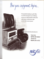
To insure your enjoyment please read and carefully follow these instructions. The time spent will make it possible
for you to enjoy thousands of hours of musical enjoyment.
If you are in a hurry read page 4 first. This gives you a
brief outline of what each control and indicator does.
Reading time for this manual is 30 minutes. This is time
well spent.
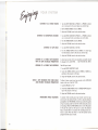
GENERAL DESCRIPTION
1
SPECIFICATIONS
3
IF YOU ARE IN A HURRY
4
CABINET
5
INSTALLATION
INSTALLATION-CONNECTIONS
7
COMPLETE SYSTEM HOOK-UP
9
BLOCK DIAGRAM
CONTENTS
.....
10
FRONT PANEL INFORMA nON
12
BALANCING
15
ENJOYING
GUARANTEE
YOUR SYSTEM
YOUR SYSTEM
16
.....
Cover
__
','ll
M'l
f.A
;--~,
••~
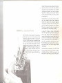
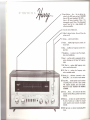
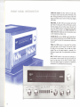
The MAC 1500 is built in three sections. Each section
built with
maximum
care and
IS
skill. Upon completion
each section is ioined with others to make a complete
unit. Each section's physical size is kept to a minimum.
The result is a compact, easy to use stereo instrument.
A stereo instrument that brings you the best in all types
of stereo listening.
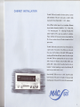
The MAC 1500 is new and exciting.
For the past three
years the advanced
products
design department
worked on this product. Every avenue and approach
was searched. New avenues were tried. New types of
circuits
were tested.
All approaches
were evaluated.
The result is a product that comes to you with an ancestry founded in the most advanced technology.
D SCRIPTION
The MAC 1500 is a stereo receiver.
venient
A product
In one small con-
easy to use unit are three top
notch stereo
components. A solid state preamplifier, a power amplifier and an FM MPX stereo tuner are combined to give
you the best performance
possible. Transistors and solid
state circuit made the MAC 1500 possible. Transistors
reduced the space necessary to combine a stereo receT~~i:,;~ith a powerful power amplifier. Solid state cirbunted on military specification
printed circuit
s are mounted vertically. This takes less space.
that
brings
you the best of both worlds.
Where tubes give superior performance and long life
they are used. Where transistors give improved performance and long life they are used. Here in one unit
you have the most advanced solid state preamplifier,
the most advanced tube and solid state multiplex circuitry, plus a conservatively rated tubed power amplifier. The FM stereo tuner comes from the same engineers
who make the tuner that AUDIO magazine called
"UNEXCELLED."
The stereo
solid state preamplifier
in the MAC
1500
gives you full sonic control of your listening room. Bass
18db of boost and cut. This
and treble controls have
±
.~
means you can control how your speakers will sound in
'!>.~.~., ..•
.{'.~ ''''~<.
~~.ce
~p~vedis used for large powerful output trans-
\
'c
i,t
f " ~ ,
~
11
'j. y-- .
~
~
WJ
~
lnf'ut
mH'l'Oli
9AtANrf
~
t4l(/~
..
JAPE
Hl\
mtus
'I •••
MO'
If
BliSS
MUT[NG lDUO
Hf
·i
VOlUM!
lKfBlE
0'
0'
1<~AOtI;Olll
(fl
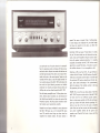
superb. The reason is simple. Pride of craftsmanship.
In tuner design, one misplaced wire, one lead length
too long, one capacitor out of place, can affect the
performance
of the tuner.
Each MAC 1500 must pass 171 tests before
it is ready
for you. The tuner section uses six tubes and two transistors. Tubes as RF amplifiers still give maximum sensi-
your particular
room. The prime function of a preampli-
fier is to reproduce records and tapes with full accuracy
and sonic realism. Records are made with the bass cut
and the highs boosted. This allows more musical information to be put on the record groove. Tapes are also
recorded with the bass cut and the highs boosted. For
true musical enjoyment the MAC 1500 reintroduces
the
bass and the highs following
accurate and definite
standards. Your records and tapes will sound alive and
tivity with greatest overload protection. It is virtually
impossible to overload the MAC 1500 with too much
signal from a nearby FM station. A transistor is used in
the oscillator because it is not susceptible to drift.
Distortion on FM is less than 0.5 %. You get all there is
to hear with this FM tuner. The MPX section of the MAC
1500 uses six transistors and two tubes. In test after test
this particular MPX section outperformed all other designs. One added advantage of the predominantly
solid state design of the multiplex
life expectancy of the circuit.
section is the long
thrilling when you hear them through the MAC 1500.
POWER. This is one thing you have plenty of with the
The solid state preamplifier
uses 12 silicon planar tran-
sistors. Silicon planar transistors are used because of
their high thermal stability, low noise and superior high
frequency response. The silicon planar transistors make
the fantastic sound reproduction possible.
Despite the small space available
the MAC
for tuner placement
1500 gives you a 2.5 microvolt
FM stereo
tuner. This sensitive tuner brings you clear noise free
reception from distant stations. The tuner section is
MAC 1500. The power output section of the MAC 1500
will drive even the most inefficient speaker systems.
Here is a dual power amplifier
with 30 watts continuous
power per channel with both channels operating.
Dis-
tortion is less than 0.5 % from 30 cycles to 20,000
cycles. Now you can listen to music with the knowledge
your power amplifier
delivers all the power your
speakers need. Good full rich music is yours with the
MAC 1500.
=""''''''''''''''~=='"'''====,'''--------~-------
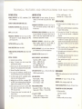
TECHNI
FM TUNER
AMPLIFIER
(at 100 % modulation):
2.5uV
SECTION:
POWER OUTPUT: 60 watts continuous,
channel, 85 watts total music power
ards).
30 watts per
(I.H.F. Stand-
SIGNAL TO NOISE AND HUM RATIO: 65db.
HARMONIC
DISTORTION:
Mono, less than .5 %
Stereo, less than .8 %
DRIFT: Less than 25KC
FREQUENCY RESPONSE: Flat from 20 cps to 20KC
with standard 75 fL second deemphasis and 19KC
pilot frequency filter.
REJECTION: Better than 60db.
STEREO MULTIPLEX SEPARATION:
at
Better than 30db
1 KC.
±
OUTPUT IMPEDANCE: 4, 8, and 16 ohms. Rated output is delivered by any of these impedances.
stereo switching.
e) Four stages of IF amplification, with AGC used to
insure that limiting occurs only in the limiter stages.
f) Two limiter stages used for exceptional capture
ratio and smooth muting operation.
g) Multiplex filter and SCA filter, to suppress 19KC
and 38KC signal components at least 40db below
program and to suppress 67KC SCA by 60db.
h) Noise immune logic circuit used to activate MPX
stereo light and automatic stereo switching on
19KC stereo pilot only.
i) D' Arsonval tuning meter for accurate center of
channel tuning.
Flywheel tuning for ease of operation
tuning.
FACTOR: Greater than 10.
INPUT SENSITIVITY
b) Muting: IF Injected circuit with at least 50db
quieting between stations.
cl Antenna inputs for 300 ohm balanced (for twin
lead) and 75 ohm unbalanced (for coaxial cable).
d) Nuvistor RF amplifier, Nuvistor mixer.
j)
INTERMODULATION
DISTORTION: Less than 0.5 %
for any combination of frequencies from 30 cps to
20KC at rated output (equivalent RMS watts). I.M.
decreases as output power is reduced.
DAMPING
SPECIAL FEATURES:
a) Automatic
HARMONIC
DISTORTION: Less than 0.5 % 30 cps to
20KC, both channels operating at rated output at
the same time.
FREQUENCY RESPONSE:
0.5db 20 cps to 20KC.
(Power amplifier response is 2 cps to 150KC at
- 3db; power bandwidth is 19 cps to 30KC.)
CAPTURE RATIO: Better than 2.0db.
IMAGE
:::'::::::···44:::
=_~",.:::",,~,,::",=
RES AND SPECIFICATIONS FOR MAC 1500
SECTION:
USABLE SENSITIVITY
(I.H.F. Standards)
=.::;;::::::;;;::.;;:;:;;;;::,::::==.
and precise
AND IMPEDANCE:
Tape Head-2.8MV,
1 megohm
Phono 1-5.6MV,
47K ohms
Phono 2-2.8MV,
47K ohms
Aux-400MV,
500K ohms
Tape Monitor-400MV,
500K ohms
TAPE OUTPUT LEVEL: Tuner-1
.2 volts, for other inputs
400MV at rated sensitivity.
Power Amplifier, - 90db
High Level Inputs, - 75db
Low Level Inputs, - 60db
+ 15db to + 15db to
FEATURES:
a) Loudness control for full fidelity
levels.
listening
at low
b) Tape monitor switch for listening to recorded tape
program while recording.
c) Tone controls are "clutched"
for tracking operation of left and right channels or independent
operation.
d) Headphone output fed from special tap on output
transformer for maximum signal to noise ratio.
Speakers may be automatically muted when headphone plug is inserted, by use of rear mounted
switch.
e) Silicon transistors used in all preamplifier stages
for low noise and hum free operation.
f) High quality epoxy circuit boards for reliable long
life performance.
g) High quality conservatively operated components
are used throughout for long life.
h) Zener regulated power supply is used for critical
circuits.
i)
Equalization and tone control circuits are feedback type for lowest distortion and greatest accuracy.
MISCELLANEOUS
panel and knobs, black finished
16" wide, 5%"
high, 16" deep.
WEIGHT: 40 lbs., shipping weight 54 lbs.
POWER CONSUMPTION:
18db at 50 cps.
- 15 db at 10KC.
L.F. and H.F. FILTER:
=
L.F. filter, cutoff frequency
50 cps,
attenuation rate
12db per octave
=
SPECIAL
DIMENSIONS:
TONE CONTROL RANGE:
Bass control
Treble control
=
FINISH: Gold anodized
chassis.
HUM AND NOISE:
=
H.F. filter, cutoff frequency
5KC
12db per octave
attenuation rate
180 watts, 120 volts, 60 cps.
TRANSISTOR AND TUBE COMPLEMENT:
19 silicon transistors
1 germanium transistor
15 tubes
16 diodes, rectifier,
and zener diode
3
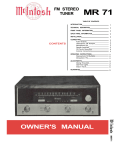
IF YOU'RE IN A
1
Input Selector ... Aux ... for any device
connected to the AUX inputs on back. FM MONO
listen to FM mono broadcasts.
FM AUTO ...
listen to FM stereo
broadcasts.
Phono
1 for
phonograph
records.
Phono 2 for phonograph
records.
Tape
hd. for a tape
playback
unit
without
preamplifier.
8AlANCE
I
TAP£
FllT(f($
MUTING
II II
MON
If
flAS~
lOUD
HF
TREBL(
O'
\I)
2
Tune for center
3
Adjust
system
to desired
on/off.
4
Tuning
...
5
Treble ... modifies
to your taste.
6
Bass ... modifies
your taste.
7
Headphone
ance stereo
8
Loud ... use this switch to compensate
for low
volume
listening
and still hear full frequency
range.
9
HF Filter In ... reduces
high
such as record surface noise.
frequency
noise
10
LF Filter In ...
such as turntable
frequency
noise
11
Muting
Muting
12
Tape Mon
monitor position
used to monitor
a recording
when used with a tape recorder
with
separate
playback
and
record
heads.
MUST BE IN OUT POSITION
FOR NORMAL
LISTENING.
13
Stereo ... Mono ... Set to stereo
program
material.
Mono position
material.
for all stereo
for all mono
14
Balance
... to make one speaker
the other.
Permits
you to adjust
sound
caused
by room acoustics
material.
louder than
for unequal
or program
15
Will light
stereo.
,,.
of black
area.
volume.
select
Power
desired
high
only
the
sounds.
Set
station.
frequency
low frequency
... to connect
headphones.
In
Out
off. Turns
reduces
rumble.
sounds.
a set of low imped-
low
eliminates
interstation
use to receive
weak
on stations
Set to
broadcasting
noise.
stations.
MPX
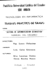
CABINET INSTALLATION
The MAC 1500 can be installed in furniture cabinets,
built installations.
top, mount it in the attractive
Allow sufficient
cabinet
internal
dimensions
13 %
cabinet
cabinet
Proper ventilation
MAC
space
inches deep, and
should
or custom
If the unit is to be used on a shelf or table
15 WO
cabinet.
for air circulation.
should
be
Minimum
inches wide,
15'l'16
inches high. The back of the
51/4
be left as open
as possible
fer ventilation.
will insure your receiver a long trouble free
life. A fan to circulate
the air will further increase
the life of
your receiver.
The MAC 1500 installs easily from the front of the cabinet into
a panel
cutout.
Four screws
mounting
Front panels
into the bottom
of any thickness
can be used.
of the MAC 1500 through
the
shelf hold the unit firmly in place. Due to the weight
of the MAC 1500 we recommend
shelf of at least
the unit rest on a wooden
1//' thickness. Unless the MAC 1500 is ade-
quately
held in place
tempted.
If vertical
c,ubic feet per minute
vertical
mounting
mounting
is used
should
not be at-
a fan delivering
50
must be used.
Since the MAC 1500 must rest on a shelf, locate
from the back of the panel.
A template
the cutout
to help you make
mounting easy is in the packet that contains the owners manual.
5
r
On the back of the cabinet panel, scribe a vertical
line through the exact center of the area to be
cut out.
2 Place the template against the back of the panel.
Match the template centerline with the scribed
centerline. The bottom of the template must rest on
the shelf.
3 On each side of the centerline of the template
there are two holes marked "B." These are the
"LOCATING
HOLES." These holes are used to
locate the front panel of the MAC 1500 with reference to the shelf behind the cabinet panel. To insure the MAC 1500 will rest on the cabinet shelf,
follow these instructions carefully.
i -,.,
--......,<~<
4 Mark the back of the cabinet panel with a pointed
instrument through the two "B" LOCATING HOLES.
Drill these two holes through the cabinet panel with
a 3/16" diameter drill. Be certain the drill is perpendicular to the panel.
S
Position the template on the front of the panel.
Align the "C" holes in the template with the drilled
holes in the cabinet paJlel.
6 Mark the "A" corner cutouts in the template. Join
the corner markers. The edge of the template can
be used as a straight edge.
7 Cut out the rectangular
FRONT
PANEL
-
-
t~-=---
,l~ - - - - -- ~.,QJ- - - - \
,
I
I
~
MARK
CORNERS
,\/1I
='1--II
-~
A.,;,
S Take
line.
front
shelf
line.
dotted
of the
of the
center-
9 Mark holes "A" and "B." Drill the holes using a
'1,4" to Y2" bit. The larger you make the holes the
more latitude you will have to position the MAC
1500.
1 0 Scribe the suggested
area.
6
opening.
the shelf template and fold along the
Put the dotted line against the back
mounting panel. Align the center line
template with the scribed front panel
cutout outline.
Cut out the
11
Prepare the MAC 1500 for mounting by removing
the four plastic feet fastened under the chassis.
12
The MAC 1500 is installed from the FRONT of the
cabinet. Insert the MAC 1500 power cord through
the rectangular
opening of the cabinet panel.
Carefully slide the MAC 1500 through the opening.
Continue to slide the MAC 1500 until its front panel
is against the cabinet mounting panel.
13
Secure the MAC 1500 to the mounting shelf using
the screws supplied in the hardware package.
14
Connect the MAC 1500 to the rest of the system.
\.-=;;~¥~~~~
k ~W#
1!
~
I::
~
0 0[[[ nco 0
.;-~:::.~.;-~
TIGHTEN
SCREWS
J
rJ·[~
00 ~
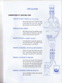
INSTALLATION
CONNECTIONS TO YOUR MAC 1500
CONNECTING THE PHONO 1 POSITION for your main record player
Connect the "left"
channel to the "L"
input of
PH
1. Connect
the "right"
channel to the "R" input of PH 1. If your record
player has a ground wire connect the ground wire to GND.
CONNECTING THE PHONO 2 POSITION
Phono 2 position can be used if two record players are used in
a system. Connect the "left" channel to the "L" input of PH 2.
Connect the "right" channel to the "R" input of PH 2.
CONNECTING TAPE PLAYER(no preamplifier in tape player)
Use this position only for a tape deck with no electronics. Connect the "left" channel to the "L" input of TAPE HD. Connect
the "right"
TAPE
channel to the "R" input of TAPE HD.
(NO
CONNECTING A TAPE RECORDERor TAPE PLAYERwith BUILT-IN ELECTRONICS
SElf
PlAYfP
CONTAINED
TAPE
TAPE
MON
ElECTRONICS)
AUX
Connect the "left" channel of the tape player or tape recorder
to the "L" channel AUX input. Connect the "right" channel of
the tape player or tape recorder to the "R" channel AUX input.
CONNECTING A TAPE RECORDERWITH THREEHEADS
Connect the tape outputs of the MAC
1500 to the high level
inputs on the tape recorder. This will make it possible for you to
record from the MAC 1500. Connect the tape recorder outputs
to the TAPE MON inputs on the MAC 1500. Use TAPE MON ...
In for listening to pre-recorded
tapes as well as to monitor.
~6
CONNECTING A TAPE RECORDERTO RECORDFROM THE MAC 1500
Connect the TAPE OUTPUTS of the MAC 1500 to the high level
Q)
TAPE
inputs on the tape recorder.
(WITH
SElf
RECORDER
CONTAINED
~
6 Gl 6\
T.V.
ElECTRONICS)
7
Connect one wire to the C (common) on the left output, connect
a second wire to the impedance that matches your loudspeaker.
,..'.
Run these two wires to the "left" loudspeaker. Connect one wire
to the C (common) on the right output, connect a second wire to
the impedance that matches your loudspeaker.
wires to the "right" loudspeaker.
Run these two
LEFT
LQUOIPEAKER
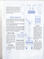
ANTENNA CONNECTIONS
rO\O~O
fBl~fBl~fBl
A convenient flexible indoor FM dipole (300 ohm) antenna is supplied
with the MAC 1500. This antenna is easy to install. It is suitable for good
FM reception in high signal areas.
Connect the two leads of the dipole antenna
\\300" on the back panel of the MAC 1500.
~~~i8
1050
to the two terminals marked
l 01
AC OUTLETS
The flexibility of the thick flat wire lets you easily locate the dipole behind
the equipment. Open the dipole into a \\T." Extend the arms as straight
as possible. The dipole antenna is somewhat directional. It should be
positioned for best reception of the desired stations.
OUTDOOR FM ANTENNA
IMPORTANT
An outdoor FM antenna is recommended.
Keep the dipole away from large metal
objects or surfaces. They interfere with
the efficiency of the antenna.
It will give you the best reception
under
all conditions. In fringe areas, a highly
directional antenna used with a rotator
will give the finest possible FM reception.
Rotate the antenna until it points in the
direction of the station or until it receives
the best possible signal.
75 OHM ANTENNA
An unbalanced 75 ohm FM antenna can
be used with the MAC 1500. Use the two
terminals marked 75.
8
MUTING (on the rear panell
This control
determines
the strength
o
of
signal necessary for a station to be heard
with the tuner in the muting position. The
muting threshold is carefully adjusted to
optimum at the factory using precision
test instruments.Casual adjustment of the
muting threshold is not recommended.
There are two BLACK AC outlets and
one RED AC outlet. The power to the
black AC outlets is controlled by the
front panel switch. Use these outlets
for accessories such as q tape recorder. The red receptacle is on at all
times and is used for a turntable or
record changer. The turntable is protected by this arrangement. It is necessary to turn off the turntable or record changer by its own AC switch.
Connect the AC cord from your record
player to the RED outlet.
00
SPKR
ON
MUTING
~
~
SPKR
Off
SPKR ON ...
OFF
This switch controls the loudspeakers
when you use the headphone jacks on
the front panel. With the switch in the
ON position the loudspeakers will remain on when you plug in the headphones. With the switch in the OFF
position the loudspeakers will turn off
when you plug in headphones.
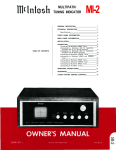
COMPLETE SYSTEM
HOOK-UP TO MAC 1500
~
J
"'i-
o
If<
LEfT
TAPE
(WITH
SElF
LOUDSPEAKER
RECORDER
CONTAINED
ELECTRONICS)
T.v.
"e~l~
10 :
0 0 I v9o~
J
MuTING
lEil;lEil~lEil
•• O~
[~H~;~ '"''''
L 010'010
'
RIGHT
RECORD PLAYER
I
RECORD PLAYER
LOUDSPEAKER
TAPE PLAYFR
2
(NO
SElF
CONTAINED
ElECTRONICS)
9
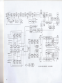
19 KC
300
OHMS
75
OHMS
/
L/
a8-IOB
//
Me
/
....t
TAPE
//
//
..J
//
OUT
TAPEMON
AUX
8
PH I
4
PH 2
C
TAPE
HD
I
I
TAPE
MONITOR
I
I
I
I
16
8
4
VOLUME
AC
LINE
MAC 1500 STEREO
10
RECEIVER
BLOCK DIAGRAM
1!()W
...
~~
Having completed
the installation
new world of musical enjoyment
-..-
.....••
- .•..
section gives you a detailed
of your MAC 1500 a
is yours. The following
explanation
of all the controls
...
and their functions.
It will tell you how to adjust
your MAC 1500 for maximum
enjoyment.
If you have any further questions please write:
Customer Service
MciNTOSH
AUDIO COMPANY
2 Chambers Street
Binghamton, New York 13903
11
I
TUNING DIAL SCALES-The
MAC 1500 has two dial scales.
The megacycle scale indicates the position of FM stations in the
88 to 108 megacycle FM band. The linear division of the 0-100
logging scale makes it easy to return to a station using a logging
scale number.
INDICATORS-The
MAC 1500 has two indicators on the front
panel. One is the tuning meter. When an FM station is correctly
tuned the indicator will be in the black area of the meter. The
action of the TUNING indicator is independent of station signal
strength. The second indicator is the STEREO INDICATOR. The
STEREO INDICATOR will light only when the dial pointer crosses
a station broadcasting multiplex stereo.
VOLUME ON-OFF-Use
the VOLUME control to adjust the volume to a desired listening level. Turn the VOLUME control clockwise to increase the volume. Full counterclockwise rotation turns
the unit off.
TREBLE-The
TREBLEcontrol is a dual control. The small knob
controls the treble in the left channel. The large knob controls
the treble in the right channel. The two knobs are friction
coupled. They can be adjusted together or separately. Turn
clockwise to increase treble. Turn counterclockwise to decrease
treble.
BASS-The
BASS control is a dual control. The small knob controls the bass in the left channel. The large knob controls the
bass in the right channel. The two knobs are friction coupled.
They can be adjusted together or separately. Turn clockwise to
increase bass. Turn counterclockwise to decrease bass.
I
INPUT SElECTOR
STUHI
MON
1M MONO
I
0'
OUI
'H
QU'
OUT
OUI
HF
IFFlll!RS
lAP!
MUTING
fUAJ)l'IHHff
BAIANCf
MONO
12
,.
lOUD
BASS
(j)
I
'H
(If
OlH
l.
'!R!m
VOWMt
0l
,-
HEADPHONE-The
headphone jack is for use with low impedance headphones. There is a switch on the rear panel to
control the loudspeakers. With the switch in the SPEAKER OFF
position the loudspeakers will turn off when you insert your headphone jack. With the switch in the SPEAKER ON position the
loudspeakers will remain in the system.
onto the tape at the record head. The signal follows a difficult
path ... the tape is played by the playback head
through
the playback preamplifier in the tape recorder
out of the
tape recorder into the tape monitor inputs on the MAC 1500
... then through the power amplifier of the MAC 1500 and to
the loudspeakers.
LOUD
An abbreviation of loudness
OUT
This is the normal position for moderate to loud
listening levels. Use the LOUD ... IN position to listen to low
listening levels. It will allow you to hear the full frequency
range. With the volume turned down there is an apparent loss
of bass and treble response. When the volume is low the
human ear's response to bass and treble decreases more
rapidly than its response to notes in the mid-range. The LOUD
control automatically
boosts the bass and treble. With the
switch IN the bass and treble are heard in correct proportion
to the mid-range at low listening levels.
CAUTION: THE SWITCH MUST BE IN THE OUT POSITION
FOR NORMAL LISTENING.
~ '"''
STEREO MON.
Stereo
Mono
for all normal stereo listening.
for all normal monophonic listening.
HF (High Frequency) FILTER-Use the HF filter switch to reduce
high frequency noise such as record scratch or hiss from tapes.
OUT
IN
filter disconnected for normal flat frequency response.
reduces high frequencies above 5,000 cycles.
LF (Low Frequency) FILTER-Use
the LF filter switch to reduce
low frequency noise such as turntable rumble or acoustic feedback coupled from the speakers to the turntable.
OUT
IN
I
filter disconnected for normal flat frequency response.
reduces low frequencies below 50 cycles. MON
STEREO
MUTING
MONO
IN ... turns on the muting circuit. Muting suppresses background hiss and noise usually heard when tuning between
stations. Weak or distant stations that cannot override the
background noise and interference are suppressed by the
muting.
II
It.l
OUT
OUT
OUT
11'1
IN
I11'1
OUT
lls
If
HF
lOUD
MUTING
lAflE
FilTERS
OUT ... turns off the muting to allow conventional tuning.
Interstation noise will be present. Use this setting to listen to
weak or distant stations that have noise or interference.
TAPE MON.
The MAC 1500 tape switch makes it possible to instantly compare recorded material with the source signal. Tape jacks on the
back panel accept a signal from a tape recorder with a monitor
head and preamplifier.
OUT ... the program source is fed through the MAC 1500 to
the loudspeakers.
IN ... the program source is fed from the MAC 1500 to the
tape output jacks to the tape recorder. The signal is recorded
/500
13
- .•
,"1i
BALANCE
Use the MAC 1500
unequal
Left ... turning the control
left channel
by reducing
output.
I
volume
BALANCE control
in the left and
to balance
right channels.
to left accents the
the right channel
Right ... turning the control to the right accents the right channel by reducing
the left
channel output.
I
INPUT
Select
anyone
of six program
FM AUTO TUNER ...
Use this position
to listen to all FM broadcasts.
The tuner
will automatically
switch to stereo
on all
stations
broadcasting
stereo. The tuner will
return to mono operation
when you tune in
a station
broadcasting
mono.
I
NOTE: IF A STEREO BROADCAST IS NOISY
YOU CAN SWITCH THE TUNER TO FM
MONO.
I
SELECTOR
INPUT
fMAIlTO~
sources
with this switch.
SElECTOR.
PHONO
1 ... connects
stereo and monophonic
the MAC 1500 for
operation
of records.
AUX--,;;.
FM 'OliO
PHONO
2 ...
Same as PHONO
1.
TAPE HD ... A tape deck that does not contain its own playback
preamplifier
is connected to the MAC 1500 through the TAPE
HD position.
FM MONO ... Use this position to listen to
FM broadcasts.
If a stereo broadcast
is noisy
you can switch the tuner to FM MONO. This
puts the tuner
section
into the monaural
mode. It will reduce noise.
!l
AUX ... any
amplification,
recorders.
14
auxiliary
service requiring
flat
such as a television set, or tape
NOTE: OWNERS OF TAPE RECORDERS WITH
SEPARATE RECORD AND PLAYBACK HEADS
USE THE TAPE MONITOR
POSITION
TO
PLAY BACK PRE-RECORDED TAPES.
SETTING YOUR CONTROLS ..""
a stereo system
The performance
and enjoyment
of your stereo system increases
tem is balanced.
There are two factors
in balancing.
loudness on the left and right channels of the program
system balance.
The control
marked
when the sys-
One is unequal
program
source. The other is basic
BALANCE on the MAC 1500 is used to cor-
rect both of these problems.
First balance
the system. There are many
your system: room acoustics,
in loudspeakers,
furniture
things which
placement,
etc.
affect
the balance
of
room shape, small differences
TO BALANCE SYSTEM
Set the stereo mono switch to MONO.
2 Playa
familiar
recording.
3 Turn the balance
4 While
control to the 12 o'clock position.
the program
loudspeakers.
is playing,
stand in the center of the two
Listen to see if there is a difference
from either speaker.
in loudness
The sound should come from a point mid-
way between the speakers. If it does not, turn the control toward the speaker that is not as loud as the other. Do this until
you find the point where the sound comes from the mid-point
ADJUSTING
Set the MONO
2 Stand about
loudspeakers.
between
PHASE
of and mid-way
The sound should appear
If it is impossible
to get the sound to
go on to ADJUSTING
PHASE. After
you have adjusted the phase you can start the balancing
cedure over again.
STEREO switch to MONO.
10 feet in front
the speakers.
come from the mid-point
between
to be directly
pro-
your
in front
of you. Have someone switch the leads on one speaker. Be sure
to switch the leads on ONE speaker only. If the sound is not
directly in front of you reverse the leads on one loudspeaker.
When the sound comes from the mid-point
between the
speakers they are in phase.
15
YOUR SYSTEM
f;,j"i#If
LISTENING
TO A STEREO RECORD
Turn the INPUT SELECTOR to PHONO 1 or PHONO 2, whichever is connected to the record player you wish to hear.
2 Set the MONO
I
STEREO switch to STEREO.
3 Adjust the VOLUME control to the desired volume.
LISTENING
I
TO MONOPHONIC
RECORDS
Turn the INPUT SELECTORTO PHONO 1, or PHONO 2, whichever is connected to the record player you wish to hear.
2 Turn the STEREOMONO switch to MONO.
3 Adjust the VOLUME control to the desired volume.
LISTENING
TO TAPE DECKS
1 Turn the INPUT SELECTOR to TAPE HD.
2 Turn the STEREO MONO switch to STEREO. If a mono tape,
turn the balance control to the side you want to hear.
3 Adjust the VOLUME control to the desired volume.
LISTENING TO A STEREO TAPE RECORDER
WITH ITS OWN PLAYBACK PREAMPLIFIER
A stereo tape recorder with its own playback preamplifier should
be plugged in the AUX INPUT ...
NOT THE TAPE HD. INPUT.
LISTENING
The AUX input is used:
TO A STEREO TAPE RECORDER
1 Turn the INPUT SELECTOR TO AUX.
2 Switch the STEREO MONO switch to STEREO or MONO
pending on the program on the tape.
de-
3 Adjust the VOLUME control to the desired volume.
USING
A TAPE RECORDER WITH
AND SEPARATE PLAYBACK
THREE HEADS
PREAMPLIFIER
To listen to tapes connect your tape recorder
inputs on the rear of the MAC 1500.
to the TAPE MON
1 Switch TAPE MON to ''IN.''
2 Switch the STEREO MONO switch to STEREOMONO
ing on the program on the tape.
depend-
3 Adjust the VOLUME control to the desired volume.
MONITORING
16
WHILE
RECORDING
To monitor while recording your tape recorder must have separate record an-d playback heads as well as separate playback
preamplifiers. The TAPE MONO switch lets you monitor the quality
of tape recording made from the MAC 1500 during the process
of recording. When the TAPE MONO switch is in the IN position
it will play the sound from the tape as it passes the playback
head, a moment after it is recorded. The recording process continues as usual. When the switch is in the OUT position normal
program from the source is heard.
Your MAC 1500 stereo
pleasant and satisfactory
concerning the operation
receiver will give you many years of
performance.
If you have any questions
or maintenance
of this receiver please contact:
E
CE
Mcintosh Audio Company
2 Chambers Street
Binghamton, New York 13903
Our telephone number is 723-5491
The area code is 607
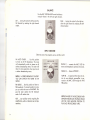
UARANTEE
Mcintosh Audio Company guarantees
this equipment to perform
as advertised.
We also guarantee
the mechanical and electrical
workmanship
and components
of this equipment
to be free of
defects for a period of 90 days from date of purchase. This guaranteedoes
not extend to components
damaged
by improper use
nor does it extend to damage incurred during transportation
to and
from Mcintosh Audio Company.
ERVICE CONTRACT
An application
for a Free Two Year Factory
Service
Contract
is
included in the packet with this manual. The Free Two Year Factory
Service Contract will be issued by Mcintosh Audio C<;>mpany upon
receipt of this completely filled out registration form. The terms of
this contract are defined in the Two Year Factory Service Contract.
If this application is not mailed to Mcintosh Audio Company, only
the service offered under the standard 90 day guarantee will apply
to this equipment.
TAKE ADV ANT AGE
SERVICE
OF 2 YEARS OF FREE FACTORY
BY FILLING
IN
THE APPLICATION
NOW
Precision craftsmanship
and painstaking
attention to finest accuracies
make the MAC
1500
meet high standards.
MCINTOSH AUDIO COMPANY
2 Chambers St., Binghamton, N. V. 13903
'\
~
~ ~
,
~
..
\..J
Made in USA
~ ~ ~~:::',:::::::~::::,':o,;,
038·093