1
SD-AT1000W(LAG)
TINSEA121AWZZ
ENGLISH
Please refer to
pages E-1 to E-32.
ESPAÑOL
1-BIT DIGITAL HOME THEATER
SISTEMA 1-BIT PARA HOME THEATER
Consulte las
páginas S-1 a S-32.
MODEL
MODELO
SD-AT1000W
OPERATION MANUAL
MANUAL DE MANEJO
SD-AT1000W_LAG_FRONT
TINSZA121AWZZ
1
ENGLISH
SD-AT1000W
ENGLISH
Introduction
Thank you for purchasing this SHARP product. To obtain the best performance from
this product, please read this manual carefully. It will guide you in operating your
SHARP product.
! SD-AT1000W 1-Bit Digital Home Theater consisting of SD-AT1000W (main unit),
CP-AT1000WF (front speakers), CP-AT1000WC (centre speaker), CP-AT1000WR
(surround speakers) and CP-AT1000WSW (subwoofer).
Important Instruction
- Introduction / Special notes / Contents -
Special notes
WARNING
! When the ON/STAND-BY button is set at STAND-BY position, mains voltage is still
present inside the unit. When the ON/STAND-BY button is set at STAND-BY position, the unit may be brought into operation by the timer mode or remote control.
! This unit contains no user serviceable parts. Never remove covers unless qualified
to do so. This unit contains dangerous voltages, always remove mains plug from
the socket before any service operation and when not in use for a long period.
! To prevent fire or shock hazard, do not expose this appliance to dripping or splashing. No objects filled with liquids, such as vases, should be placed on the apparatus.
Manufactured under license from Digital Theater Systems, Inc. US Pat. No.
5,451,942, 5,956,674, 5,974,380, 5,978,762 and other world-wide patents
issued and pending. “DTS” and “DTS Digital Surround” are registered trademarks of Digital Theater Systems, Inc. Copyright 1996, 2000 Digital Theater Systems, Inc. All Rights Reserved.
Contents
" General Information
Page
Accessories . . . . . . . . . . . . . . . . . . . . . . . . . . . . . . . . . . . . . . . . . . . . . . . . . . . . . . . 2
Precautions . . . . . . . . . . . . . . . . . . . . . . . . . . . . . . . . . . . . . . . . . . . . . . . . . . . . . . . 2
Controls and indicators . . . . . . . . . . . . . . . . . . . . . . . . . . . . . . . . . . . . . . . . . . 3 - 8
" System connections
Speaker connection . . . . . . . . . . . . . . . . . . . . . . . . . . . . . . . . . . . . . . . . . . . . . 9, 10
Aerial connection . . . . . . . . . . . . . . . . . . . . . . . . . . . . . . . . . . . . . . . . . . . . . . . . . 10
Audio connections to DVD players, VCRs, TVs, etc. . . . . . . . . . . . . . . . . . . 11, 12
Connecting the AC power lead . . . . . . . . . . . . . . . . . . . . . . . . . . . . . . . . . . . . . . 13
" Preparation for Use
Setting the AM/FM interval . . . . . . . . . . . . . . . . . . . . . . . . . . . . . . . . . . . . . . . . . . 14
System installation . . . . . . . . . . . . . . . . . . . . . . . . . . . . . . . . . . . . . . . . . . . . . . . . 15
Remote control . . . . . . . . . . . . . . . . . . . . . . . . . . . . . . . . . . . . . . . . . . . . . . . . . . . 16
General control . . . . . . . . . . . . . . . . . . . . . . . . . . . . . . . . . . . . . . . . . . . . . . . . . . . 17
Setting the clock . . . . . . . . . . . . . . . . . . . . . . . . . . . . . . . . . . . . . . . . . . . . . . . . . . 18
" Basic Operation
Listening to the radio . . . . . . . . . . . . . . . . . . . . . . . . . . . . . . . . . . . . . . . . . . . 19, 20
Listening to the playback sound from DVD players, VCRs, etc. . . . . . . . . . . . . 21
Enjoying various sounds . . . . . . . . . . . . . . . . . . . . . . . . . . . . . . . . . . . . . . . 22 - 24
" Advanced Features
Adjusting speaker delay/speaker level . . . . . . . . . . . . . . . . . . . . . . . . . . . . . 25, 26
Timer and sleep operation . . . . . . . . . . . . . . . . . . . . . . . . . . . . . . . . . . . . . . 27 - 29
Manufactured under license from Dolby Laboratories. “Dolby”, “Pro Logic”
and the double-D symbol are trademarks of Dolby Laboratories.
" References
Troubleshooting chart . . . . . . . . . . . . . . . . . . . . . . . . . . . . . . . . . . . . . . . . . . 30, 31
Maintenance . . . . . . . . . . . . . . . . . . . . . . . . . . . . . . . . . . . . . . . . . . . . . . . . . . . . . 31
Error indicators and warnings . . . . . . . . . . . . . . . . . . . . . . . . . . . . . . . . . . . . . . . 31
Optional accessory . . . . . . . . . . . . . . . . . . . . . . . . . . . . . . . . . . . . . . . . . . . . . . . . 31
Specifications . . . . . . . . . . . . . . . . . . . . . . . . . . . . . . . . . . . . . . . . . . . . . . . . . . . . 32
E-1
04/7/21
SD-AT1000W_LAG_E1.fm
TINSZA121AWZZ
SD-AT1000W(LAG) TINSZA121AWZZ
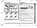
Accessories
Precautions
Please confirm that the following accessories are included.
" General
2
SD-AT1000W
ENGLISH
1
! Please ensure that the equipment is positioned in a well ventilated area and that
there is at least 10 cm (4") of free space along the sides and back. There must
also be a minimum of 15 cm (6") of free space on the top of the unit.
10 cm (4")
Remote control
1
AM loop aerial
1
FM aerial
10 cm (4")
2
15 cm (6")
1
10 cm (4")
Purple
(for subwoofer)
approx. 5m (15 feet)
Green
(for centre speaker)
approx. 5m (15 feet)
Blue
(for left surround speaker)
approx. 15m (45 feet)
Speaker connection lead
Note:
Only the above accessories are included.
Red
(for right front speaker)
approx. 5m (15 feet)
Grey
(for right surround speaker)
approx. 15m (45 feet)
6
- Accessories / Precautions -
White
(for left front speaker)
approx. 5m (15 feet)
"AA" size battery (UM/SUM-3, R6,
HP-7 or similar) 2
3
General Information
Antislip speaker cushion sheet
(20 pcs.) 1
! Use the unit on a firm, level surface free from vibration.
! Keep the unit away from direct sunlight, strong magnetic fields, excessive dust,
humidity and electronic/electrical equipment (home computers, facsimiles, etc.)
which generates electrical noise.
! Do not place anything on top of the unit.
! Do not expose the unit to moisture, to temperatures higher than 60°C (140°F) or to
extremely low temperatures.
! If the unit does not work properly, unplug and plug it in again. Then turn on the
unit.
! In case of an electrical storm, unplug the unit for safety.
! Hold the AC power plug by the head when removing it from the wall socket, as
pulling the lead can damage internal wires.
! Do not remove the outer cover, as this may result in electric shock. Refer
internal service to your local SHARP service facility.
! The ventilation should not be impeded by covering the ventilation openings with
items, such as newspapers, tablecloths, curtains, etc.
! No naked flame sources, such as lighted candles, should be placed on the apparatus.
! Attention should be drawn to the environmental aspects of battery disposal.
! This unit should only be used within the range of 5°C - 35°C (41°F - 95°F).
4
5
6
Warning:
The voltage used must be the same as that specified by this unit. Using this product
with a higher voltage other than that specified is dangerous and may result in a fire or
other types of accident, causing damage. SHARP will not be held responsible for any
damage resulting from the use of this unit with a voltage other than that specified.
7
" Volume control
The sound level at a given volume setting depends on speaker efficiency, location,
and various other factors. It is advisable to avoid exposure to high volume levels. Do
not turn the volume on to full at switch on and listen to music at moderate levels.
8
E-2
04/7/21
SD-AT1000W_LAG_E1.fm
TINSZA121AWZZ
SD-AT1000W
ENGLISH
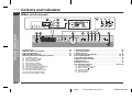
Controls and indicators
" Main unit (front panel)
1
- Controls and indicators -
General Information
6
2
3
4
5
(1)
(2) (3) (4) (5) (6) (7)
15
(1)
(2)
(3)
(4)
(5)
(6)
(8)
(9) (10)(11)
7
(12) (13)
9
8
10 11 12 13
Reference page
1. Sleep Indicator . . . . . . . . . . . . . . . . . . . . . . . . . . . . . . . . . . . . . . . . .
2. FM Stereo Receiving Indicator . . . . . . . . . . . . . . . . . . . . . . . . . . . .
3. Timer Play Indicator . . . . . . . . . . . . . . . . . . . . . . . . . . . . . . . . . . . . .
4. FM Stereo Mode Indicator . . . . . . . . . . . . . . . . . . . . . . . . . . . . . . . .
5. Audio Signal Indicators/Speaker Indicators . . . . . . . . . . . . . . . . .
(1)
(2)
(3)
(4)
(5)
(6)
(7)
(8)
(9)
(10)
(11)
(12)
(13)
Subwoofer Indicator
Left Front Speaker Indicator
Front Left Signal Indicator
Centre Signal Indicator
Centre Speaker Indicator
Front Right Signal Indicator
Right Front Speaker Indicator
Low Frequency Effect Signal Indicator
Left Surround Speaker Indicator
Surround Left Signal Indicator
Surround Monaural Signal Indicator
Surround Right Signal Indicator
Right Surround Speaker Indicator
29
19
27
19
22
14
Reference page
6. On/Stand-by Button . . . . . . . . . . . . . . . . . . . . . . . . . . . . . . . . . . . . . .13
7. Timer Set Indicator . . . . . . . . . . . . . . . . . . . . . . . . . . . . . . . . . . . . . .28
8. Volume Control . . . . . . . . . . . . . . . . . . . . . . . . . . . . . . . . . . . . . . . . . .17
9. Tuning Up and Down Buttons . . . . . . . . . . . . . . . . . . . . . . . . . . .14, 19
10.Tuner (Band) Button . . . . . . . . . . . . . . . . . . . . . . . . . . . . . . . . . .14, 19
11.Line Input Select Button . . . . . . . . . . . . . . . . . . . . . . . . . . . . . . . . . .21
12.Digital Input Select Button . . . . . . . . . . . . . . . . . . . . . . . . . . . . . . . .21
13.Remote Sensor . . . . . . . . . . . . . . . . . . . . . . . . . . . . . . . . . . . . . . . . .16
14.Headphone Socket . . . . . . . . . . . . . . . . . . . . . . . . . . . . . . . . . . . . . . .17
15.Sound Mode Indicators . . . . . . . . . . . . . . . . . . . . . . . . . . . . .22, 23, 24
(1)
(2)
(3)
(4)
(5)
(6)
DTS Signal Indicator
Dolby Digital Signal Indicator
Dolby Pro Logic Indicator
Surround Indicator
Standard Indicator
Stereo Indicator
E-3
04/7/21
SD-AT1000W_LAG_E1.fm
TINSZA121AWZZ
SD-AT1000W
ENGLISH
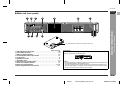
" Main unit (rear panel)
1
2
3
4
6
5
1
7
2
9
10
11
The rating label is located on the bottom of the unit.
Reference page
1. FM 75 Ohms Aerial Socket . . . . . . . . . . . . . . . . . . . . . . . . . . . . . . . . 10
2. Aerial Earth Terminal . . . . . . . . . . . . . . . . . . . . . . . . . . . . . . . . . . . . . 10
3. AM Loop Aerial Terminal . . . . . . . . . . . . . . . . . . . . . . . . . . . . . . . . . . 10
4. Coaxial Digital Audio Input Socket . . . . . . . . . . . . . . . . . . . . . . . . . 11
5. Cooling Fan . . . . . . . . . . . . . . . . . . . . . . . . . . . . . . . . . . . . . . . . . . . . . 4
6. Speaker Terminals . . . . . . . . . . . . . . . . . . . . . . . . . . . . . . . . . . . . . . . . 9
7. AC Power Lead . . . . . . . . . . . . . . . . . . . . . . . . . . . . . . . . . . . . . . . . . . 13
8. Subwoofer Pre Output Socket . . . . . . . . . . . . . . . . . . . . . . . . . . . . . 12
9. Audio Line Output Sockets . . . . . . . . . . . . . . . . . . . . . . . . . . . . . . . 11
10.Audio Line Input Sockets . . . . . . . . . . . . . . . . . . . . . . . . . . . . . . 11, 12
11.Optical Digital Audio Input Socket . . . . . . . . . . . . . . . . . . . . . . . . . . 11
Cooling fan
This unit is fitted with a cooling fan at the rear for improved cooling. Do not cover the
opening in this section with any obstacles.
- Controls and indicators -
8
General Information
3
Cooling fan
Caution:
! The unit will get warm whilst being used. Do not touch the warm areas of the unit
for prolonged periods to avoid damage to you.
! This unit is equipped with a special function which protects the amplifier circuit
from damages. When it is activated, the sound switch is turned off. In this case,
set the unit to the stand-by mode and turn on again.
4
5
6
7
8
E-4
04/7/21
SD-AT1000W_LAG_E1.fm
TINSZA121AWZZ
SD-AT1000W
Controls and indicators (continued)
ENGLISH
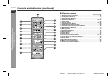
" Remote control
1
2
3
Reference page
12
13
- Controls and indicators -
General Information
14
4
5
15
16
6
17
7
18
8
19
9
20
10
21
1. Remote Control Transmitter . . . . . . . . . . . . . . . . . . . . . . . . . . . . . . .16
2. TV Operation Buttons . . . . . . . . . . . . . . . . . . . . . . . . . . . . . . . . . . . . .6
3. VCR Operation Buttons . . . . . . . . . . . . . . . . . . . . . . . . . . . . . . . . . . . .6
4. Input Select Buttons . . . . . . . . . . . . . . . . . . . . . . . . . . . . . . . . . .19, 21
5. Clear Button . . . . . . . . . . . . . . . . . . . . . . . . . . . . . . . . . . . . . . . . . . . .20
6. Cursor Buttons . . . . . . . . . . . . . . . . . . . . . . . . . . . . . . . . . . . . . . .18, 25
7. Amplifier Return Button . . . . . . . . . . . . . . . . . . . . . . . . . . . . . . . . . .25
8. Amplifier Initial Setting Button . . . . . . . . . . . . . . . . . . . . . . . . . . . . .25
9. 2-channel Stereo Sounds Select Button . . . . . . . . . . . . . . . . . . . . .24
10.DVD Operation Buttons . . . . . . . . . . . . . . . . . . . . . . . . . . . . . . . . . . . .6
11.Muting Button . . . . . . . . . . . . . . . . . . . . . . . . . . . . . . . . . . . . . . . . . .17
12.On/Stand-by Button . . . . . . . . . . . . . . . . . . . . . . . . . . . . . . . . . . . . . .16
13.Dimmer Button . . . . . . . . . . . . . . . . . . . . . . . . . . . . . . . . . . . . . . . . . .17
14.Clock Button . . . . . . . . . . . . . . . . . . . . . . . . . . . . . . . . . . . . . . . . . . . .18
15.Timer Button . . . . . . . . . . . . . . . . . . . . . . . . . . . . . . . . . . . . . . . . . . .27
16.Tuning Up and Down Buttons . . . . . . . . . . . . . . . . . . . . . . . . . . .14, 19
17.Tuner Preset Up and Down Buttons . . . . . . . . . . . . . . . . . . . . . . . . .20
18.Enter Button . . . . . . . . . . . . . . . . . . . . . . . . . . . . . . . . . . . . . . . . . . . .14
19.Sound Mode Select Button . . . . . . . . . . . . . . . . . . . . . . . . . . . . . . . .23
20.Multi Channel Select Button . . . . . . . . . . . . . . . . . . . . . . . . . . . . . . .23
21.Volume Up and Down Buttons . . . . . . . . . . . . . . . . . . . . . . . . . . . . .17
11
E-5
04/7/21
SD-AT1000W_LAG_E1.fm
TINSZA121AWZZ
SD-AT1000W
ENGLISH
It is possible to operate some functions of Sharp TVs, VCRs and DVD players with your new SD-AT1000W remote control. However some models may not respond.
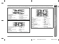
TV Operation Buttons
DVD Operation Buttons
1
4
1
7
5
2
8
3
9
4
10
5
11
6
12
2
6
5 TV CHANNEL
Switches up the TV channels.
6 TV VOLUME +
Turns up the TV volume.
1 DVD
7
Selects the DVD menu.
2 DVD RETURN
Goes back to the previous screen.
3 DVD ENTER
Validates the menu.
8
9
DVD MENU
Displays the DVD menu.
DVD
Plays back the DVD.
DVD
Stops the DVD player.
4
4 DVD
10 DVD
2
5
Selects the DVD menu.
5 DVD ON/STAND-BY
Selects the DVD menu.
11 DVD SKIP
3
6
1 VCR ON/STAND-BY
Sets the VCR power to "ON" or
"STAND-BY".
2 VCR
Rewinds the cassette quickly.
3 VCR TV/VCR
Switches the input to TV or VCR.
4 VCR
Stops the cassette.
Sets the DVD power to "ON" or
"STAND-BY".
6 DVD
Selects the DVD menu.
3
Skip up the DVD chapters.
12 DVD SKIP
Skip down the DVD chapters.
- Controls and indicators -
4 TV CHANNEL
Switches down the TV channels.
VCR Operation Buttons
1
2
General Information
3
1 TV ON/STAND-BY
Sets the TV power to "ON" or
"STAND-BY".
2 TV VOLUME Turns down the TV volume.
3 TV TV/VCR
Switches the input to TV or VCR.
1
5 VCR
4
5
6
7
Plays the cassette.
6 VCR
Advances the cassette quickly.
8
E-6
04/7/21
SD-AT1000W_LAG_E1.fm
TINSZA121AWZZ
SD-AT1000W
Controls and indicators (continued)
ENGLISH
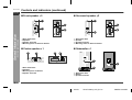
" Front speaker 2
" Surround speaker 2
1
1
3
3
2
4
4
- Controls and indicators -
General Information
2
1. Bass Reflex Duct
2. Speakers
3. Speaker Terminals
4. Mounting Holes for Stand or Bracket
1. Bass Reflex Duct
2. Speaker
3. Speaker Terminals
4. Mounting Holes for Stand or Bracket
" Centre speaker 1
1
2
" Subwoofer 1
3
4
1
3
1. Bass Reflex Duct
2. Speakers
3. Mounting Holes for Bracket
4. Speaker Terminals
2
1. Bass Reflex Duct
2. Woofer
3. Speaker Terminals
E-7
04/7/21
SD-AT1000W_LAG_E1.fm
TINSZA121AWZZ
SD-AT1000W
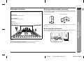
" Speaker functions
ENGLISH
" Using antislip speaker cushions
Reproduces left and right sound (for the stereo mode) or front surround sound.
You can install the front, centre or surround speakers either vertically or horizontally.
Affix the cushions (supplied) to the bottom of the speakers to prevent them from sliding or falling due to vibration.
Centre speaker:
(Vertical position)
Front speaker:
1
2
(Horizontal position)
Reproduces centre surround sound.
Surround speaker:
Reproduces rear surround sound.
Reproduces bass sound.
A sheet of speaker cushions (20 pcs.) is supplied with this product. Use 4 cushions
per speaker.
" Carrying the subwoofer
When carrying the subwoofer, be careful not to touch the subwoofer located near bottom. It may be damaged. Be sure to hold the unit by its base.
(For speaker installation, refer to page 15.)
Notes:
- Controls and indicators -
Subwoofer:
General Information
3
4
5
6
Subwoofer
! Do not allow any objects to fall into or to be placed in the bass reflex ducts.
! The speakers grilles are not removable.
! Front, centre and subwoofer speakers are magnetically shielded.
7
8
E-8
04/7/21
SD-AT1000W_LAG_E1.fm
TINSZA121AWZZ
SD-AT1000W
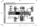
Speaker connection
ENGLISH
The speaker terminals on the main unit, the tube and plugs of the speaker lead, and speaker labels are distinguished by colours.
Connect the speaker and the unit by matching the colours.
(For speaker installation, refer to page 15.)
Surround speaker
(left)
Front speaker
(left)
Centre speaker
Red
Red
White
Black
Black
Red
Green
Blue
- Speaker connection -
System connections
Blue
Black
Green
White
Purple
Grey
Red
Red
Instead of the supplied subwoofer, you can connect separately available woofer to enjoy more of the bass sound
(see page 12).
Red
Red
Grey
Black
Black
Black
Red
Purple
Surround speaker
(right)
Front speaker
(right)
Subwoofer
E-9
04/7/21
SD-AT1000W_LAG_E2.fm
TINSZA121AWZZ
SD-AT1000W(LAG) TINSZA121AWZZ
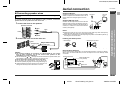
Aerial connection
SD-AT1000W
ENGLISH
Supplied FM aerial:
Make sure to leave the AC power lead disconnected when connecting the
speakers.
To prevent accidental short circuit between
and
speaker wires to the speakers first then to the unit.
terminals, connect the
Connect the FM aerial wire to the FM 75 OHMS
socket and position the FM aerial wire in the direction where the strongest signal can be received.
Supplied AM loop aerial:
Connect the AM loop aerial wire to the AM and
GND terminals. Position the AM loop aerial for
optimum reception. Place the AM loop aerial on
a shelf, etc., or attach it to a stand or a wall with
screws (not supplied).
1 Connect the wires to the speakers.
Speaker terminals
Red
2
Black
White
Notes:
! Placing the aerial on the unit or near the AC power lead may cause noise pickup.
Place the aerial away from the unit for better reception.
! When static is still heard even after adjusting the position of the AM loop aerial, try
reversing the wire connections.
Black
2 Connect the other end to the main unit.
Installing the AM loop aerial:
< Assembling >
Label
Speaker plug
< Attaching to the wall >
Plug in with the rising
side facing up.
Wall
Screws (not supplied)
External FM or AM aerial:
Caution:
! The supplied speakers are exclusively for SD-AT1000W. Do not connect
them to other equipment, and do not connect other speakers to SDAT1000W. It may cause malfunction.
! Do not mistake the and , and right and left terminals of the speaker leads. (The
right speaker is placed on the right when you face the unit.)
! Do not let the bare speaker wires touch each other.
! Do not stand or sit on the speakers. You may be injured.
! Insert the speaker plug fully with the rising side facing up.
! Hold the speaker plug when removing it from the main unit.
Pulling the lead may cause malfunction to the unit.
Use an external FM or AM aerial if you require better reception. Consult your dealer.
When using an external AM aerial, be sure to keep the wire of the AM loop aerial
connected.
External FM aerial
External AM aerial
15 m (49 feet)
System connections
Tube
Label
4
5
6
Earth wire
AM loop
aerial
8
Incorrect
E-10
04/7/21
3
7
7.5 m (25 feet)
Earth rod
1
AM loop
aerial
FM aerial
- Speaker connection / Aerial connection -
" Connecting speaker wires
3
SD-AT1000W_LAG_E2.fm
TINSZA121AWZZ
SD-AT1000W
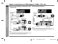
Digital audio cable
(commercially
available)
" Connecting a VCR, etc.
Audio cable
(commercially
available)
To coaxial digital
audio input socket
To audio
output sockets
To optical digital
audio input socket
Optical digital cable
Digital tuner, etc.
(commercially available)
TV
Audio signal
To optical digital
audio output socket
TV
To audio
input sockets
Audio signal
System connections
" Connecting a DVD player (CD player), digital tuner, etc.
Audio signal
- Audio connections to DVD players, VCRs, TVs, etc. -
ENGLISH
Audio connections to DVD players, VCRs, TVs, etc.
Audio cable
(commercially
available)
VCR, etc.
DVD player
(CD player), etc.
To audio
input sockets
TV
Audio signal
To coaxial digital
audio output socket
To audio
output sockets
Notes:
! The LINE 1 OUT sockets emit signals from the LINE 2 IN, LINE 3 IN and the builtin tuner. Signals from the DIGITAL IN and LINE 1 IN are not emitted.
! Connect TV directly to the DVD player, VCR or digital tuner to watch programmes
(refer to the operation manual of each equipment).
Notes:
! This unit has DIGITAL IN 1 (coaxial) and DIGITAL IN 2 (optical) sockets for digital
input. Select either according to the output socket of your equipment.
! When connecting with an optical digital cable, set the digital output of the digital
tuner to PCM. Refer to the operation manual of the digital tuner.
E-11
04/7/21
SD-AT1000W_LAG_E2.fm
TINSZA121AWZZ
SD-AT1000W
2
To audio
output sockets
To audio
input sockets
Commercially
available subwoofer
(amplifier built in)
TV
Audio signal
Audio cable
(commercially available)
To subwoofer
output socket
Subwoofer signal
To subwoofer
input socket
Audio cable
(commercially available)
To audio
input sockets
Other
equipment
Audio signal
Audio cable
(commercially
available)
1
For a greater emphasis of bass, a commercially available subwoofer, with a
built in amplifier, can be connected to the unit using the SUBWOOFER PRE
OUT socket.
Notes:
! No sound is heard from the speaker in which an amplifier is not built in.
! When not using the supplied subwoofer, disconnect the speaker wire from the
main unit.
! The speaker delay and level settings are applied to the subwoofer connected to
the SUBWOOFER PRE OUT socket (see pages 25 and 26).
To audio
output sockets
Caution:
Turn off all other equipment before making this connection.
System connections
You can enjoy surround sound from TVs or other equipment by connecting
them to the unit as shown.
ENGLISH
" Using other subwoofer
- Audio connections to DVD players, VCRs, TVs, etc. -
" Audio connection to TVs or other equipment
Notes:
3
4
5
6
7
! Refer to the operation manual of the equipment to be connected.
! Insert the plugs fully to avoid fuzzy pictures or noise.
8
E-12
04/7/21
SD-AT1000W_LAG_E2.fm
TINSZA121AWZZ
SD-AT1000W
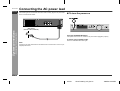
Connecting the AC power lead
ENGLISH
After checking all the connections have been made correctly, plug the AC power lead
of this unit into the wall socket.
" To turn the power on
- Connecting the AC power lead -
System connections
Wall socket
(AC 220 - 240 V, 50/60 Hz)
Press the ON/STAND-BY button.
If the power does not turn on, check the AC power lead is plugged in properly.
To set the unit to stand-by mode:
Press the ON/STAND-BY button again.
Note:
Unplug the AC power lead from the wall socket if the unit will not be in use for a prolonged period of time.
E-13
04/7/21
SD-AT1000W_LAG_E2.fm
TINSZA121AWZZ
Setting the AM/FM interval
SD-AT1000W
ENGLISH
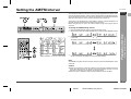
The International Telecommunication Union (ITU) has established that member countries should maintain either a 10 kHz or 9 kHz interval between broadcasting frequencies of AM stations and 100 kHz or 50 kHz for FM stations. The illustration shows the
50/9 kHz zones (regions 1 and 3), and the 100/10 kHz zone (region 2).
This product is not equipped with a span selector. However, it will be adjusted to a 10
kHz AM (100 kHz FM) interval when shipped from the factory.
Before using the unit, be sure to set it to the AM/FM tuning interval (span) used in
your area.
1
2
To change the AM/FM tuning interval:
3
Within 6 seconds, press the TUNING ( or ) button to select the interval (span)
in your area.
The display switches each time you press the button.
4
Within 6 seconds, press the ENTER button on the remote control.
! The unit will enter the power stand-by mode automatically.
Note:
3
- Setting the AM/FM interval -
Press the ON/STAND-BY button to enter the stand-by mode.
Whilst holding down the TUNER (BAND) button, press the ON/STAND-BY button.
Preparation for Use
1
2
4
5
6
The AM/FM tuning interval will not change unless you press the ENTER button within
6 seconds.
7
Caution:
! When the unit is left for a few hours after the span has been switched and the AC
power lead disconnected, the AM span will be automatically returned to 10 kHz
(FM span to 100 kHz). If this happens, set the span again.
! When the span is switched, all the memorised stations will be cancelled.
8
E-14
04/7/21
SD-AT1000W_LAG_E2.fm
TINSZA121AWZZ
SD-AT1000W
ENGLISH
System installation
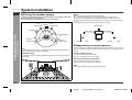
" Placing the speaker system
Notes:
The best surround effect will be achieved by placing each speaker at the same
distance from the listening position.
It is recommended to arrange the speakers as shown below.
Front
speaker (left)
Centre
speaker Front
speaker (right)
!
!
!
!
Place the TV halfway between the front speakers.
It is recommended that the centre speaker be placed near the television.
Place the surround speakers at a position just above the height of your ears.
The subwoofer vibrates whilst reproducing bass. Place it on a stable, sturdy surface.
! The subwoofer reproduces bass. Place it anywhere you like.
Centre speaker
Subwoofer
Same distance
Default setting:
2m
- System installation -
Preparation for Use
Same distance
Surround
speaker (left)
Surround
speaker (right)
Front speaker (left)
Front speaker (right)
" Magnetically shielded speakers
Note:
The default distance is set to 2 m. If speakers cannot be placed at equal distances,
refer to "Speaker delay setting" (see page 25).
Installation image:
The speaker stands are optionally available (see page 31). Refer to their instructions
for assembly.
The front, centre and subwoofer speakers may be placed beside or near the TV as
they are magnetically shielded. However, discolouration may occur depending on the
TV type.
If colour variation occurs...
Turn off the TV (from the power switch).
After 15 - 30 minutes, turn the TV on again.
If the colour variation is still present...
Move the speakers further away from the TV.
Refer to the user's manual of the TV for details.
Note:
The surround speakers are not magnetically shielded.
E-15
04/7/21
SD-AT1000W_LAG_E2.fm
TINSZA121AWZZ
Remote control
SD-AT1000W
ENGLISH
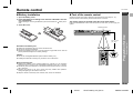
" Battery installation
" Test of the remote control
1 Open the battery cover.
2 Insert the batteries according to the direction indicated in the battery compartment.
Check the remote control after checking all the connections (see pages 9 - 13).
Point the remote control directly at the remote sensor on the unit.
When inserting or removing the batteries, push them towards the
nals.
battery termi-
3 Close the cover.
The remote control can be used within the range shown below:
1
2
Press the ON/STAND-BY button. Does the power turn on? Now, you can enjoy your
system.
Remote sensor
Precautions for battery use:
! Replace all old batteries with new ones at the same time.
! Do not mix old and new batteries.
! Remove the batteries if the unit is not to be used for long periods of time. This will
prevent potential damage due to battery leakage.
Caution:
! Do not use rechargeable batteries (nickel-cadmium battery, etc.).
! Installing the batteries incorrectly may cause the unit to malfunction.
- Remote control -
0.2 m - 6 m
(8" - 20')
Preparation for Use
3
4
5
6
Notes concerning use:
! Replace the batteries if the operating distance is reduced or if the operation
becomes erratic. Purchase 2 "AA" size batteries (UM/SUM-3, R6, HP-7 or similar).
! Periodically clean the transmitter on the remote control and the sensor on the unit
with a soft cloth.
! Exposing the sensor on the unit to strong light may interfere with operation.
Change the lighting or the direction of the unit.
! Keep the remote control away from moisture, heat, shock, and vibrations.
7
8
E-16
04/7/21
SD-AT1000W_LAG_E2.fm
TINSZA121AWZZ
SD-AT1000W
General control
ENGLISH
" To change the display brightness (2 levels)
You can switch the display brightness by pressing the DIMMER button.
Display
Dimmed
" Volume control
Main unit operation:
When the VOLUME control is turned clockwise,
the volume will increase. When it is turned anticlockwise, the volume will decrease.
0
1
2 .....
39
40
Press the VOLUME + button to increase the volume and the VOLUME - button for decreasing.
" Muting
- General control -
Preparation for Use
Remote control operation:
The volume is muted temporarily when pressing
the MUTING button on the remote control.
Press again to restore the volume.
" Headphones
! Before plugging in or unplugging the headphones, reduce the volume.
! Be sure your headphones have a 6.3 mm (1/4") diameter plug and are between 16
ohms and 50 ohms impedance. The recommended impedance is 32 ohms.
! Plugging in the headphones disconnects the speakers automatically. Adjust the
volume using the VOLUME control.
! You cannot use the surround feature with headphones.
! Do not plug in or unplug headphones whilst recording. The sound may skip.
E-17
04/7/21
SD-AT1000W_LAG_E2.fm
TINSZA121AWZZ
SD-AT1000W(LAG) TINSZA121AWZZ
Setting the clock
SD-AT1000W
ENGLISH
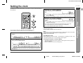
By setting the unit to the correct time, you can use it not only as a clock but also for
timer playback.
4
3
1
Press the or button to adjust the
hour and then press the ENTER button.
2
! Press the or button once to advance the time by 1 hour. Hold it down to
advance continuously.
! When the 12-hour display is selected, "AM" will change automatically to "PM".
Press the or button to adjust the
minutes and then press the ENTER
button.
! Press the or button once to advance the time by 1 minute. Hold it down
to advance continuously.
! The hour will not advance even if minutes advance from "59" to "00".
! The clock starts from "0" second (seconds are not displayed).
! The time disappears after approx. 5 seconds.
To confirm the time display:
Press the CLOCK button.
The time display will appear for about 5 seconds.
You can set the clock even when the unit is in the stand-by mode.
In this example, the clock is set for the 24-hour (0:00) display.
1
Press the CLOCK button and within 5 seconds, press the ENTER
button.
Note:
The "ADJUST" or time will flash at the push of the CLOCK button when the AC power
supply is restored after a power failure or unplugging the unit.
Readjust the clock as follows.
To readjust the clock:
Perform "Setting the clock" from step 1. If the "ADJUST" is not flashing in step 1, step
2 (for selecting the 24-hour or 12-hour display) will be skipped.
2
Press the or button to select the 24-hour or 12-hour display and
then press the ENTER button.
4
5
6
To change the 24-hour or 12-hour display:
1
2
"0:00"
"12:00 AM"
"AM 0:00"
- Setting the clock -
3
Preparation for Use
4
Clear all the programmed contents. [Refer to "Clearing all the memory (reset)" on
page 31 for details.]
Perform "Setting the clock" from the beginning.
7
The 24-hour display will appear. (0:00 - 23:59)
The 12-hour display will appear. (AM 12:00 - PM 11:59)
The 12-hour display will appear. (AM 0:00 - PM 11:59)
8
Note that this can only be set when the unit is first installed or it has been reset
(see page 31).
E-18
04/7/9
SD-AT1000W_LAG_E3.fm
TINSZA121AWZZ
SD-AT1000W
ENGLISH
Listening to the radio
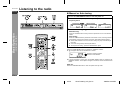
" Manual or Auto tuning
1 Press the ON/STAND-BY button to turn the power on.
2 Press the TUNER (BAND) button repeatedly to select the desired
frequency band.
FM monaural
FM stereo
3
Press the TUNING (
or
AM
) button to tune in to the desired station.
Press the TUNING button as many times as required to tune in to the desired
station.
- Listening to the radio -
Basic Operation
Manual tuning:
Auto tuning:
When the TUNING button is pressed for 0.5 seconds or more, scanning will start
automatically and the tuner will stop at the first receivable broadcast station.
! When radio interference occurs, auto scan tuning may stop automatically at
that point.
! Auto scan tuning will skip weak signal stations.
! To stop the auto tuning, press the TUNING button again.
To receive an FM stereo transmission:
Press the TUNER (BAND) button to display the "STEREO" indicator.
! " " will appear when an FM broadcast is in stereo.
FM stereo receiving indicator
FM stereo mode indicator
! If the FM reception is weak, press the TUNER (BAND) button to extinguish the
"STEREO" indicator. The reception changes to monaural, and the sound becomes
clearer.
After use:
Press the ON/STAND-BY button to enter the power stand-by mode.
E-19
04/7/9
SD-AT1000W_LAG_E3.fm
TINSZA121AWZZ
SD-AT1000W
" Memorising a station
You can store 40 AM and FM stations in memory and recall them at the push of a button. (Preset tuning)
Perform steps 1 - 3 in "Manual or Auto tuning" on page 19.
1
2
Press the TUNER PRESET ( or
tion.
2
Within 5 seconds, press the TUNER
PRESET ( or ) button to select
the preset channel number.
Within 5 seconds, press the ENTER
button to store that station in memory.
" To erase all the contents of the preset
memory
1
2
3
3
Frequency and frequency band
Press the ON/STAND-BY button to turn the power on, and press the TUNER/
BAND button.
Hold the CLEAR button down for 3 seconds or more.
Whilst "CLEAR" is flashing, press the ENTER
button.
Repeat steps 1 - 4 to set other stations, or to change a preset station.
When a new station is stored in memory, the station previously memorised will
be erased.
- Listening to the radio -
Store the stations in memory, in order, starting with preset channel 1.
5
) button to select the desired sta-
Press the ENTER button to enter the preset tuning saving mode.
Preset channel
4
1
Press the TUNER (BAND) button.
Basic Operation
1
2
3
ENGLISH
" To recall a memorised station
4
5
6
Note:
The backup function protects the memorised stations for a few hours should there be
a power failure or the AC power lead disconnection.
7
8
E-20
04/7/9
SD-AT1000W_LAG_E3.fm
TINSZA121AWZZ
SD-AT1000W
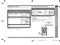
Listening to the playback sound from DVD players, VCRs, etc.
ENGLISH
Basic Operation
- Listening to the playback sound from DVD players, VCRs, etc. -
1
2
3
Turn on the connected equipment.
Press the ON/STAND-BY button to turn the power on.
Select the source by pressing the DIGITAL or LINE button repeatedly.
DIGITAL 1
DIGITAL 2
LINE 1
LINE 2
LINE 3
You can select the source directly on the remote control.
4
5
Press the play button of the connected equipment.
Adjust the volume level with the VOLUME control (see page 17).
Caution:
The unit gets warm when used for a long time. This is not a malfunction.
Note:
A safety feature automatically sets the unit to the power stand-by mode if you set the
volume level too high. If this happens, lower the volume level.
E-21
04/7/9
SD-AT1000W_LAG_E3.fm
TINSZA121AWZZ
Enjoying various sounds
SD-AT1000W
ENGLISH
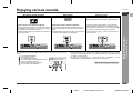
DTS (Digital Theater Systems)
Dolby Digital
1
Dolby Pro Logic
Inputs from stereo-recorded discs, video tapes, etc.
2
When playing stereo discs/videos or 2-channel stereo
sounds recorded in Dolby Digital, the Dolby Pro Logic
function reproduces the sound in 5.1-channel digital surround sound, ensuring more natural sound effects.
One of the digital audio systems for theatrical use. As the One of the digital audio systems for theatrical use. You
sound quality is emphasised, you can enjoy the realistic can enjoy the stereophonic effect in the home theatre
sound effect in the home theatre system.
system.
The DTS indicator will light up when the disc recorded in The DOLBY DIGITAL indicator will light up when the disc When the Dolby Pro Logic
DTS is played back.
recorded in DOLBY DIGITAL is played back.
dicator will light up.
3
function is activated, the in-
Audio signal indicators / Speaker indicators:
Caution:
The audio signal indicator or speaker indicator lights up according to the input audio
source.
Front Left Signal Indicator
Centre Signal Indicator
Audio signal indicator
Front Right Signal Indicator
Speaker indicator
LFE (Low Frequency Effect) Signal Indicator
Surround Left Signal Indicator
2
3
1
Surround Monaural Signal Indicator
Surround Right Signal Indicator
! When connecting the DVD player to the LINE 1/2/3 IN sockets, the surround sound
recorded in Dolby Digital or DTS is not available. (Refer to the operation manual
for details on audio output.)
! To record sound with VCR, etc., set the sound mode to "STEREO". If set to
"STANDARD" or "SURROUND", the sound will not be recorded.
- Enjoying various sounds -
Digital input from discs with this trademark
Basic Operation
Digital input from discs with this trademark
4
5
6
Refer to the next page for operations
4
7
5
6
7
8
E-22
04/7/9
SD-AT1000W_LAG_E4.fm
TINSZA121AWZZ
SD-AT1000W
Enjoying various sounds (continued)
ENGLISH
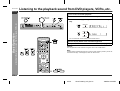
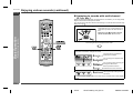
" Listening to sounds with multi-channel
(5.1 ch, etc.)
When connecting the DVD player to the DIGITAL IN 1/2 sockets, you can enjoy Dolby
Digital or DTS sounds with spacious effects.
You can also enjoy spacious effects when listening to 2-channel stereo sounds using
Dolby Pro Logic .
Whilst the disc is playing, press the MULTI CHANNEL button.
- Enjoying various sounds -
Basic Operation
A maximum of 5.1ch surround sound is reproduced to provide three-dimensional effect.
Dolby Pro Logic expands 2-channel
stereo sound of CDs, etc. to 5.1 ch.
Surround types can be changed in this mode.
Press the SOUND MODE button.
Each press of the button changes the mode.
The bass level is increased for
powerful sound effect.
You can enjoy the original sound
as it is.
You can enjoy lively sound by producing the clear sound.
Soft but powerful sound is
achieved even at low volumes.
This mode provides an expansive
listening area by emitting 2-channel sound.
You cannot select "SURROUND" if the audio source contains DTS or Dolby Digital
signals.
E-23
04/7/9
SD-AT1000W_LAG_E4.fm
TINSZA121AWZZ
SD-AT1000W
ENGLISH
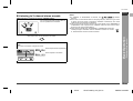
" Listening to 2-channel stereo sounds
Whilst the disc is playing, press the STEREO button.
You can enjoy the great acoustic effects of
the front speakers and subwoofer.
Notes:
! If "STEREO" or "SURROUND" is selected, the "
" indicator
goes out.
! Some discs are recorded at 96 kHz of sampling frequency. When this type of disc
is played, the sound mode is changed to "STEREO" automatically. The sound
mode cannot be changed during playback.
! The monaural sound is heard only from the centre speaker in the "STANDARD" or
"SURROUND" mode. If played in the "STEREO" mode, the same sound is reproduced from the right and left speakers.
! When switching to AM radio, "STANDARD" or "SURROUND" mode automatically change to "STEREO" and the "STEREO" indicator is lit. However, AM broadcasts cannot be received in stereo.
1
2
3
Press the SOUND MODE button to turn the "BASS ON" or "BASS
OFF".
Each press of the button changes the mode.
Bass frequencies are emphasised.
Bass emphasis is cancelled.
- Enjoying various sounds -
Basic Operation
Bass frequencies can be switched in this mode.
4
5
6
7
8
E-24
04/7/9
SD-AT1000W_LAG_E4.fm
TINSZA121AWZZ
SD-AT1000W
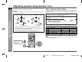
Adjusting speaker delay/speaker level
ENGLISH
When speakers cannot be placed at equal distances, change speaker settings to
enjoy surround effects as if they were equally placed.
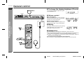
Step 1. Speaker delay setting
Example:
By adjusting speaker delay, differences in speaker distance can be corrected. This
offers you the sound quality as if the speakers are installed at the same distance from
the listening position.
If the right surround speaker is 3 m away from the listening position, change settings
as shown below (adjust the SR).
CT
FL
Advanced Features
- Adjusting speaker delay/speaker level -
SW
FR
SW
SR
Default setting: 2 m
1
2
FL
FR
SL
1
Press the AMP SET UP button, and the or
DELAY". Then press the ENTER button.
2
Within 30 seconds, press the
speaker.
3
Within 30 seconds, press the
or button to select the distance
and press the ENTER button.
CT
SL
3m
SR
or
button to select "SP
button to select the desired
! You can change the distance in 0.1 m steps.
! To set the distance of other speakers, repeat the operation from step 2.
Right surround
speaker
3
In "Speaker delay setting", set the right surround speaker (SR) to 3.0 m.
In "Speaker level setting", slightly increase the level of the right surround speaker
as it is a little farther than others (see page 26).
In "Test tone", check the sound from each speaker (see page 26).
4
When you complete the settings, press the AMP RETURN button twice.
FL
CT
Speaker type
Front speaker (Left)
Centre speaker
Delay range
0.1 m to 9.0 m
0.1 m to 9.0 m
Default setting
2.0 m
2.0 m
FR
SR
SL
SW
Front speaker (Right)
Surround speaker (Right)
Surround speaker (Left)
Subwoofer
0.1 m to 9.0 m
0.1 m to 9.0 m
0.1 m to 9.0 m
0.1 m to 9.0 m
2.0 m
2.0 m
2.0 m
2.0 m
Note:
You can also adjust the speaker delay of a subwoofer connected to the SUBWOOFER PRE OUT socket.
You can return to the
previous menu during operations.
E-25
04/7/9
SD-AT1000W_LAG_E4.fm
TINSZA121AWZZ
SD-AT1000W(LAG) TINSZA121AWZZ
5
SD-AT1000W
ENGLISH
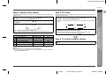
Step 2. Speaker level setting
Step 3. Test tone
If sounds from the speakers are uneven, you can equalise them by adjusting the
speaker levels.
After adjustments, check the speaker sound by listening to the test tone. (You can
readjust the volume level.)
2
Within 10 seconds, press the
speaker.
3
Within 10 seconds, press the
or
or
button to select "SP
Speaker type
Front speaker (Left)
Centre speaker
Front speaker (Right)
SR Surround speaker (Right)
SL Surround speaker (Left)
SW Subwoofer
Press the AMP SET UP button, and the
"TONE". Then press the ENTER button.
button to adjust the level.
Level range
Default setting
- 6 dB to + 6 dB
- 6 dB to + 6 dB
- 6 dB to + 6 dB
0 dB
0 dB
0 dB
- 6 dB to + 6 dB
- 6 dB to + 6 dB
- 10 dB to + 10 dB
0 dB
0 dB
+ 6 dB
or
button to select
2
Speakers emit the test tone for 2 seconds in turn, starting with the front speaker
(left).
button to select the desired
! You can adjust the level at 1 dB intervals.
! To adjust the levels of other speakers, repeat the operation from step 2.
FL
CT
FR
1
2
FL
CT
FR
SW
SL
SR
3
Readjust the speaker levels if not equal.
Whilst the test tone sounds, press the or button to adjust the level.
You can select a speaker by pressing the or button.
Step 4. To end the speaker setting
When you complete the settings, press the AMP RETURN button
twice.
Notes:
! If subwoofer sound is distorted, lower the subwoofer level.
! You can also adjust the speaker level of a subwoofer connected to the SUBWOOFER PRE OUT socket.
Advanced Features
Press the AMP SET UP button, and the or
LEVEL". Then press the ENTER button.
- Adjusting speaker delay/speaker level -
1
1
4
5
6
7
8
E-26
04/7/9
SD-AT1000W_LAG_E4.fm
TINSZA121AWZZ
SD-AT1000W
Timer and sleep operation
ENGLISH
You can use the unit as an alarm clock by setting the timer.
- Timer and sleep operation -
Advanced Features
Before setting timer:
1
Set the unit to the correct time (page 18).
If it is not set, you cannot use the timer function.
2
Prepare the sound source for playback.
3
Store radio stations (page 20).
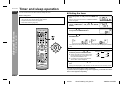
" Setting the timer
1 Turn the power on and press the TIMER button.
Set the unit to the correct time if "TIMER STANDBY"
does not appear.
2
Within 10 seconds, press the or button to
select "TIMER SET", and press the ENTER
button.
3
Press the or button to adjust the hour and
then press the ENTER button.
4
Press the or
ENTER button.
button to adjust the minutes and then press the
The start time is set and the finish time (1 hour later) will be displayed automatically.
5
6
7
Set the time to finish as in steps 3 and 4 above.
Switch input with the or button,
and then press the ENTER button.
DIGITAL1
DIGITAL2
! When you select the tuner, select a station by pressing the or button, and
then press the ENTER button.
! If a station has not been programmed,
"NO P-SET" will be displayed.
TUNER
LINE1
LINE3
LINE2
Adjust the volume with the
ton.
or
button and press the ENTER but-
Settings are displayed in order and the unit will enter the timer stand-by mode.
Caution:
This unit cannot set the timer of other equipment.
To perform the timer playback using other equipment, you should also set the
timer on the equipment separately.
E-27
04/7/21
SD-AT1000W_LAG_E5.fm
TINSZA121AWZZ
SD-AT1000W
ENGLISH
After completing the setting
1
To check the timer setting:
1 Whilst in the timer playback stand-by mode,
press the TIMER button.
When the timer setting is completed:
2
The unit is in the timer playback
stand-by mode.
2 Within 10 seconds, press the or
button to select "TIMER CALL", and
press the ENTER button.
The unit returns to the timer playback stand-by mode after the setting contents
are displayed in order.
Playback starts automatically and the volume
increases gradually.
The unit is operated by the timer.
Timer play indicator flashes
Timer playback is cancelled by turning the power on whilst in the timer playback
stand-by mode. The same operation can be performed in the following procedure
without turning the power on.
1 Press the TIMER button.
"TIMER CANCEL" will appear.
2 Within 10 seconds, press the ENTER button.
Timer playback will be cancelled (the contents of the setting will not be cancelled).
Reusing the timer:
Using the same setting;
When the finish time is reached:
The unit is set to the power stand-by mode automatically.
The timer setting is canceled.
Caution:
The contents of the setting will be erased if the unit is unplugged or a power failure
occurs. In such cases, set the timer again.
The timer setting will be memorised once it is entered. To reuse the same setting,
perform the following operations.
1 Turn the power on and press the TIMER button.
"TIMER STANDBY" will appear. If it does not appear, set the unit to the correct
time.
2 Within 10 seconds, press the ENTER button.
After the setting contents are displayed in order, the unit is set to the timer
playback stand-by mode.
- Timer and sleep operation -
Cancelling the timer playback:
When the start time is reached:
Advanced Features
3
4
5
6
7
Changing the setting;
Turn the power on, and repeat the operation from step 1 in "Setting the timer"
(page 27).
8
E-28
04/7/21
SD-AT1000W_LAG_E5.fm
TINSZA121AWZZ
SD-AT1000W
Timer and sleep operation (continued)
ENGLISH
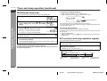
" Setting the sleep timer
You can set the unit to the power stand-by mode at the specified time.
1
To confirm the remaining sleep time:
1
2
Whilst "SLEEP" is indicated, press the TIMER button.
Within 10 seconds, press the or button to select "SLEEP".
During playback, press the TIMER button.
Remaining sleep time
3
- Timer and sleep operation -
Advanced Features
2
Within 10 seconds, press the or button to
select "SLEEP SET", and press the ENTER
button.
Press the
or
button to select the time.
(Maximum: 2 hours - Minimum: 1 minute)
! 2 hours - 5 minutes 5-minute intervals
! 5 minutes - 1 minute 1-minute intervals
4
Press the ENTER button.
"SLEEP" will appear.
5
The unit will enter the power stand-by mode automatically after the
preset time has elapsed.
The volume will be turned down 1 minute before the sleep operation finishes, and
then you cannot change the volume.
! The remaining sleep time is displayed for about 10 seconds.
! You can change the remaining sleep time whilst it is displayed by pressing the
ENTER button (steps 3 - 4).
To cancel the sleep operation:
Press the ON/STAND-BY button whilst "SLEEP" is indicated.
To cancel the sleep operation without setting the system to the stand-by mode, proceed as follows.
1 Press the TIMER button.
2 Within 10 seconds, press the or button to select "SLEEP OFF", and press the
ENTER button.
" To use timer and sleep operation together
You can fall asleep and wake up to the radio.
1
Caution:
This unit cannot set the sleep timer of other equipment.
To use the sleep timer using other equipment, you should also set the timer on
the equipment separately.
Set the sleep timer (steps 1 - 4).
Sleep operation starts.
2
Set the timer playback.
("Setting the timer" on page 27, steps 1 - 7)
1 Sleep timer setting
2 Timer playback setting
Start time
1 minute
- 2 hours
1minute
- 2hours
Sleep operation
starts.
Sleep operation will
automatically stop.
Finish time
Desired time
Timer playback
starts.
Timer playback will
automatically stop.
E-29
04/7/21
SD-AT1000W_LAG_E5.fm
TINSZA121AWZZ
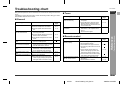
Troubleshooting chart
SD-AT1000W
Symptom
No sound is heard.
Possible cause
! Is the volume level set to "0"?
! Are the headphones connected?
! Are the speaker wires disconnected?
Reference
page
P. 17
P. 17
P. 9
! Are the speaker leads connected to
the wrong channels?
P. 9
P. 15
Noise is heard during playback.
! Is each speaker placed at the same
distance from the listener?
! Are speakers adjusted to the same
level?
! Move the unit away from any computers or mobile phones.
! Set this unit to the power stand-by
mode and then turn it back on. If the
unit still malfunctions, reset it.
! Did you remove the plug from the
wall socket, or did a power failure
occur? Reset the clock and timer.
P. 31
Timer playback does not
start.
The display on the unit is
dark.
The power is not turned on.
Possible cause
The radio makes unusual
noises continuously.
The sounds from speakers
are not well balanced.
When a button is pressed,
the unit does not respond.
Symptom
The preset channel cannot
be recalled.
! Is the unit placed near the TV or
computer?
! Is the FM aerial or AM loop aerial
placed properly? Move the aerial
away from the AC power lead or the
unit if located near.
! Did you remove the plug from the
wall socket, or did a power failure
occur?
Reference
page
P. 10
2
P. 20
3
Set the channel again.
" Remote control
P. 26
Possible cause
Reference
page
P. 16
P. 17
Is the battery polarity respected?
Are the batteries dead?
Is the distance or angle incorrect?
Are there any obstructions in front of
the unit?
! Is the remote control sensor exposed to strong light (inverter fluorescent light, direct sunlight, etc.)?
! Is the unit unplugged?
P. 13
! Is the remote control for other equipment being used simultaneously?
! The protection circuit may be activated. Unplug and plug in the power
lead again after 5 minutes or more.
P. 31
! Is the display in the dimmer mode?
1
P. 10
Symptom
The remote control does not
operate properly.
P. 18
!
!
!
!
The unit cannot be turned on ! Is the AC power lead of the unit
with the remote control.
plugged in?
! Are the batteries inserted?
P. 16
P. 16
References
" General
ENGLISH
" Tuner
- Troubleshooting chart -
Many potential problems can be resolved by the owner without calling a service technician.
If something is wrong with this product, check the following before calling your authorised SHARP dealer or service centre.
4
5
6
P. 13
P. 16
7
8
E-30
04/7/21
SD-AT1000W_LAG_E5.fm
TINSZA121AWZZ
SD-AT1000W
Troubleshooting chart (continued)
Error indicators and warnings
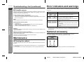
! If trouble occurs
When you fail to perform operations properly, the following messages are displayed
on the unit.
ENGLISH
References
- Maintenance / Error indicators and warnings / Optional accessory -
When this product is subjected to strong external interference (mechanical shock,
excessive static electricity, abnormal supply voltage due to lightning, etc.) or if it is
operated incorrectly, it may malfunction.
Display
If such a problem occurs, do the following:
1 Set the unit to the stand-by mode and turn the power on again.
2 If the unit is not restored in the previous operation, unplug and plug in the unit, and
then turn the power on.
" The cooling fan on the back of the main unit does not
run due to foreign objects caught in it.
Set this unit to the stand-by mode and remove the
foreign objects around the fan.
" The digital audio input socket is not connected properly.
" Turn off the unit and check if the cable is properly
connected.
Note:
If neither operation above restores the unit, clear all the memory by resetting it.
Clearing all the memory (reset)
1
2
3
Unplug the unit.
Whilst holding down the ON/STAND-BY button, plug in the AC power lead.
At this time, the unit will not be turned on.
Press the ON/STAND-BY button again to turn the power on.
Caution:
This operation will erase all data stored in memory and restore various settings to the
initial status (default).
When the protection circuit is activated:
Occasionally at very high volume levels, the protection circuit may be activated to set
the unit to the stand-by mode.
Unplug the unit and, after 5 minutes or more, plug it in again.
Turn down the volume if set too high.
Maintenance
Meaning
" Place the unit away from noise source or plug the
AC power lead to another wall socket. (*)
" Unspecified signal is received and cannot be recognised.
(*): Should the same message appear even if the unit is unplugged and plugged in or
is set to the stand-by mode and on again, contact your local dealer where you purchased the unit.
Optional accessory
Use only the specified optional accessory to operate this product properly.
For speaker installation, read instructions supplied with stands.
FLOOR SPEAKER
STAND
Model: AD-AT11ST
! Cleaning the cabinet
Periodically wipe the cabinet with a soft cloth and a diluted soap solution, then with a
dry cloth.
" Do not use chemicals for cleaning (petrol, paint thinner, etc.). It may damage the
cabinet finish.
" Do not apply oil to the inside of the equipment as this may cause malfunctions.
The appearance of optional accessory may differ from the illustration above.
E-31
04/7/21
SD-AT1000W_LAG_E5.fm
TINSZA121AWZZ
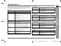
Specifications
SD-AT1000W
ENGLISH
Frequency range
Audio input terminals
Audio output
terminals
Dimensions
Weight
RMS: 100 W (10 % T.H.D., 1 kHz)
Surround speakers:
RMS: 200 W (100 W + 100 W) (10 % T.H.D., 1 kHz)
Subwoofer:
RMS: 100 W (10 % T.H.D., 100 Hz)
7th-order
(delta - sigma) modulation
FM: 88 - 108 MHz
AM: 530 - 1,620 kHz
Coaxial digital input (DIGITAL 1): RCA type 1
Optical digital input (DIGITAL 2): Square type 1
Analogue input (LINE 1): RCA type 1 pair (L/R)
Analogue input (LINE 2): RCA type 1 pair (L/R)
Analogue input (LINE 3): RCA type 1 pair (L/R)
Front speakers, Centre speaker, Surround speakers and
Subwoofer: 4 ohms
Headphones: 16 - 50 ohms (recommended: 32 ohms)
Subwoofer Pre Out: 10 k ohms
Analogue output (LINE 1): RCA type 1 pair (L/R)
Width: 430 mm (16-7/8")
Height: 67 mm (2-9/16")
Depth: 324 mm (12-3/4")
4.0 kg (8.8 lbs.)
1
Full range speaker system (magnetic shield)
8 cm (3-1/8") speaker 2
4 ohms
Width: 105 mm (4-1/8")
Height: 251 mm (9-7/8")
Depth: 125 mm (4-7/8")
1.5 kg (3.3 lbs.)/each
Weight
2
! Centre speaker
3
Type
Full range speaker system (magnetic shield)
8 cm (3-1/8") speaker 2
4 ohms
Width: 251 mm (9-7/8")
Height: 105 mm (4-1/8")
Depth: 125 mm (4-7/8")
1.5 kg (3.3 lbs.)
Impedance
Dimensions
Weight
! Surround speaker
Type
Impedance
Dimensions
Full range speaker system
8 cm (3-1/8") speaker
4 ohms
Width: 105 mm (4-1/8")
Height: 251 mm (9-7/8")
Depth: 125 mm (4-7/8")
Weight
0.9 kg (2.0 lbs.)/each
4
- Specifications -
AC 220 - 240 V, 50/60 Hz
70 W
2.8224 MHz (64fs) 1-bit switching (remarks: fs = 44.1 kHz)
Front speakers:
RMS: 200 W (100 W + 100 W) (10 % T.H.D., 1 kHz)
Centre speaker:
A/D noise shaping
Type
Impedance
Dimensions
! Main unit
Power source
Power consumption
Amplification system
Output power
! Front speaker
References
As part of our policy of continuous improvement, SHARP reserves the right to make
design and specification changes for product improvement without prior notice. The
performance specification figures indicated are nominal values of production units.
There may be some deviations from these values in individual units.
5
6
! Subwoofer
Type
Impedance
Dimensions
16 cm (6-1/4") woofer (magnetic shield)
4 ohms
Width: 240 mm (9-1/2")
Height: 408 mm (16-1/16")
Depth: 306 mm (12")
Weight
6.3 kg (13.9 lbs.)
7
8
E-32
04/7/21
SD-AT1000W_LAG_E5.fm
TINSZA121AWZZ
MEMO/MEMORÁNDUM
SD-AT1000W_LAG_memo1
TINSZA121AWZZ
MEMO/MEMORÁNDUM
SD-AT1000W_LAG_memo2
TINSZA121AWZZ
SHARP CORPORATION
0401_B5
TINSZA121AWZZ
04G R HK 1
SD-AT1000W_LAG_BACK
TINSZA121AWZZ